Article

V2G Strategy for Primary Frequency Control of an Industrial Microgrid Considering the Charging Station Operator

by
Sheeraz Iqbal
1,2,*,
Ai Xin
1,
Mishkat Ullah Jan
1,
Salman Salman
1,
Atta ul Munim Zaki
2,3,
Haseeb Ur Rehman
1,
Muhammad Fahad Shinwari
4 and
Mohamed Abdelkarim Abdelbaky
5,6
1
School of Electrical and Electronic Engineering, North China Electric Power University, Beijing 102206, China
2
Department of Electrical Engineering, University of Azad Jammu and Kashmir, Muzaffarabad 13100, Pakistan
3
School of Electronic, Information, and Electrical Engineering, Shanghai Jiao tong University, Shanghai 200240, China
4
School of Electrical & Computer Science (SEECS), National University of Science and Technology, Islamabad 45710, Pakistan
5
School of Control and computer Engineering, North China Electric Power University, Beijing 102206, China
6
Department of Electrical Power and Machines, Faculty of Engineering, Cairo University, Giza 12613, Egypt
*
Author to whom correspondence should be addressed.
Electronics 2020, 9(4), 549; https://doi.org/10.3390/electronics9040549
Submission received: 18 February 2020 / Revised: 24 March 2020 / Accepted: 24 March 2020 / Published: 25 March 2020
(This article belongs to the Section Electrical and Autonomous Vehicles)

Abstract

:
Electric vehicles (EVs) have been receiving greater attention as a tool for frequency control due to their fast regulation capability. The proliferation of EVs for primary frequency regulation is hampered by the need to simultaneously maintain industrial microgrids dispatch and EV state of charge levels. The current research aims to examine the operative and dominating role of the charging station operator, along with a vehicle to grid strategy; where, indeterminate tasks are executed in the microgrid without the EVs charging/discharging statistics. The role of the charging station operator in regulation is the assignment of the job inside the primary frequency control capacity of electric vehicles. Real-time rectification of programmed vehicle to grid (V2G) power ensures electric vehicles’ state of charge at the desired levels. The proposed V2G strategy for primary frequency control is validated through the application of a two-area interconnected industrial micro-grid and another microgrids with renewable resources. Regulation specifications are communicated to electric vehicles and charging station operators through an electric vehicle aggregator in the proposed strategy. At the charging station operator, V2G power at the present time is utilized for frequency regulation capacity calculation. Subsequently, the V2G power is dispatched in light of the charging demand and the frequency regulation. Furthermore, V2G control strategies for distribution of regulation requirement to individual EVs are also developed. In summary, the article presents a novel primary frequency control through V2G strategy in an industrial microgrid, involving effective coordination of the charging station operator, EV aggregator, and EV operator.

1. Introduction

Fossil fuels have been one of the major contributors in the growing apprehension surrounding climate change. The use of transportation utilizing conventional fuels has contributed approximately 15% of net global carbon emissions [1]. To cope with this predicament, electric vehicles (EVs) are gaining more and more popularity, with global stock reaching 5 million in 2018, increasing by over 63% in the previous year [2]. The incessant energy concerns and climate corrections suggest a further growth in the replacement of conventional automobiles by electric ones in the future [3]. EVs are also regarded as the new energy vehicles drawing greater interest, owing to their higher efficiencies and higher performance [4]. In parallel, there has been a mushroom growth of industrial microgrids (IMGs), largely stemming from the conglomeration of relatively smaller industries into large ones and the concomitant installation of distributed energy resources (DERs).
These developments have proven to be the harbinger of innovative amalgamations of industrial microgrids with utilization of EVs. The concept of vehicle to grid (V2G) has thus become an important research focus as it is providing useful means of interactions among IMGs and EVs [5], with EVs being treated as distributed generators (DGs) capable of supplementing the grid, leading to better management and stability [6].
Electricity supply by generation and energy storage sites are analogous to grid to vehicle (G2V) and vehicle to grid (V2G) discharging. Still, the focus on distributed energy resources (DERs) in the progressing IMGs in industrial zones has been limited, partly due to the peculiar requirements of industrial loads, such as induction motors, heavy machinery, or elevators, and their interaction with renewable energy resources (RERs) and batteries, including EVs [7]. However, with the rapid growth of EVs, this area is slated to receive its due attention in the world, where every kWh of electricity is important [8]; even more so when the increased mainstreaming of EVs can lead to a sharp increase in the load on the grid when a large number of EVs are in charging states at night times, compromising the grid stability. This, in addition to necessitating a systematic charging of EVs, also calls for innovative strategies, such as vehicle to grid (V2G) models; the first of which was proposed by Kempton et al. in 1997 [9]. In addition to assuaging the rapid spikes in grid loads, V2G command can also help with voltage stability, spinning reserve, peak load shifting, and frequency regulation [10]. However, primary frequency regulation has been regarded as the most promising aspect of V2G technology.
Numerous researchers have worked on frequency regulation of MGs. For instance, Reference [11] incorporated droop control strategy for improving primary frequency stabilization performance. EV supported models serve to appraise the active reaction in primary frequency control (PFC). In References [12,13], an improved adaptive droop control (ADC) strategy is suggested because it can control the charging/discharging of EVs better. EV charging can be regulated in a real-time droop coefficient in response to the primary frequency, the energy storage of the EV battery, and through control of the EV output power [14].
Some researchers have investigated the probable income linked with EV participation in V2G frequency regulation [15]. In addition to economic value, the corresponding performance has also been investigated as it could be a cause of cynicism for participation in the V2G strategy. The “master slave grid control method” is a technique relying primarily on the intercommunication lines, which suffers from the drawback of decreasing system reliability and expansion capacity [16]. As a consequence, the droop control method seems the most promising substitute. Droop characteristics have been employed in power management strategies to design effective micro grids [17]. However, the design is only applicable to electronically interconnected, fast, and dispatch-able sources of power. This leads to the introduction of the adaptive neuro-fuzzy inference system [12]. A state-of-the-art droop controller has also been used to regulate the grid frequency using battery storage of EVs [18]. However, this technique suffered from the demerit of ignoring several important battery parameters, including initial state of charge and charge/discharge rates of batteries. This problem was further rectified in Reference [19], where the researchers employed a dual droop synchronized approach for V2G strategy implementation to regulate power fluctuations. Unlike previous studies, this approach considered the impact of charge/discharge rates; however, no discernible impact was observed on EV charge/discharge mechanisms.
Similarly, novel V2G control strategies emphasize the regulation of the EV power output, based on the frequency fluctuations, to limited success, owing to the ignoring time to reach the estimated state of charge (SOC), as well as not considering the EV energy needs [14]. Some researchers modified the current droop control pattern by adding a proportional controller for sharing power, as per a set system to the available DERs [20]. Battery storage systems have been commonly employed to control microgrid frequency fluctuations [18]. The main problem faced during such strategies has been the failure to achieve the desired SOC.
The primary frequency control (PFC) of a distributed grid through V2G strategy involves giving a direct alert to grid management in case of frequency disturbance. It primarily deals with V2G and charging/discharging station management and is rooted in frequency modulation signals from the grid operator. The maximum power delivered by each EV is capped at 20 KWs [21]; however, the cut in power for PFC is on the order of several MWs [22]. Therefore, the EV aggregators must be controlled by the grid operator to execute PFC. The controllable load (batteries, EVs) capacity is an important parameter for grid operators in V2G strategy to regulate the primary frequency signal to EVs. However, the state of charge (SOC) limit in this case is not totally conferred in such cases [23].
The main function of applying the frequency regulation strategy is to maintain the frequency levels as close to nominal frequency as possible. In case the electric load surpasses the generation, frequency levels exceed the threshold of nominal frequency, e.g., by 50 Hz. On the flip side, where generation exceeds the load, the frequency falls below nominal limits. Therefore, to maintain the frequency levels at steady nominal frequency levels requires a subtle balance in load and generation. Two levels of frequency regulations are usually attained: primary and secondary regulation. Primary regulation utilizes the generator’s governor reaction to fluctuations in the rotor speed to apprehend the frequency fluctuations [24]. The restoration is done in secondary regulation, where the automatic generation control brings the frequency to nominal levels.
The latest research is focused on the utilization of artificial intelligence techniques for PFC. In this context [25], incorporated particle swarm optimization (PSO) through artificial neural networks (ANNs) adjust the proportional integral derivative (PID) controller parameters in microgrid architecture. To this end, the simulation results exhibit an increased stability in the system by PSO-based techniques. Additionally, another research proposed a novel adaptive approach for the most commonly prevalent fractional-order fuzzy PID (FOFPID) architecture of the controller used in EVs, capable of supporting load frequency control (LFC) in off-grid MGs [26]. Similarly, the impact of false data induction on the resilience of MGs has also been extensively studied [27]. The stability and resilience of an unstructured power supply mechanism can be verily restored by efficient load frequency control (LFC) in MGs [28].
In this research, control strategies for EV application in an industrial microgrid for PFC is proposed. The systematic model consists of an EV aggregator, EVs, and the charging station operator (CSO) for PFC in context of EV aggregation. The EV aggregator can communicate with the IMG operator, CSO, or individual EV. In parallel, the EV aggregator also estimates the frequency regulation capacity and the expected V2G power available from the EV. Subsequent to receiving a regulatory signal from the EV aggregator, as per the proposed V2G control methods, a control signal is sent to the EV. The CSO dispatches the frequency regulation capacity (FRC) information to the EV aggregator, which is estimated based on the present V2G power at each charging station. The EV aggregator makes decisions according to the aggregated FRC and EV V2G power without any SOC information of EV batteries. The expected battery SOC levels of EV customers can be achieved because the EV V2G power of each EV is determined according to the battery SOC level.
The V2G strategy presented here factors in the regulation of primary frequency control and the estimated SOC limits of EVs. The EV charging and discharging patterns have to be dispatched in real-time to the industrial microgrid operator for management of up-and-down frequency regulation. For estimating the charging demand and achieving the primary frequency regulation, a closed-loop V2G strategy is suggested in this article. The hierarchical model employs an intermediate execution by the IMG operator for achieving primary frequency regulation. The FRC of EVs is rooted in real-time rectification of the V2G coordinated power. The CSO has a direct control of the V2G in the charging station system to ensure anticipated SOC limits of EV batteries. Therefore, the following aspects related to V2G strategy for the PFC should be considered:
1)
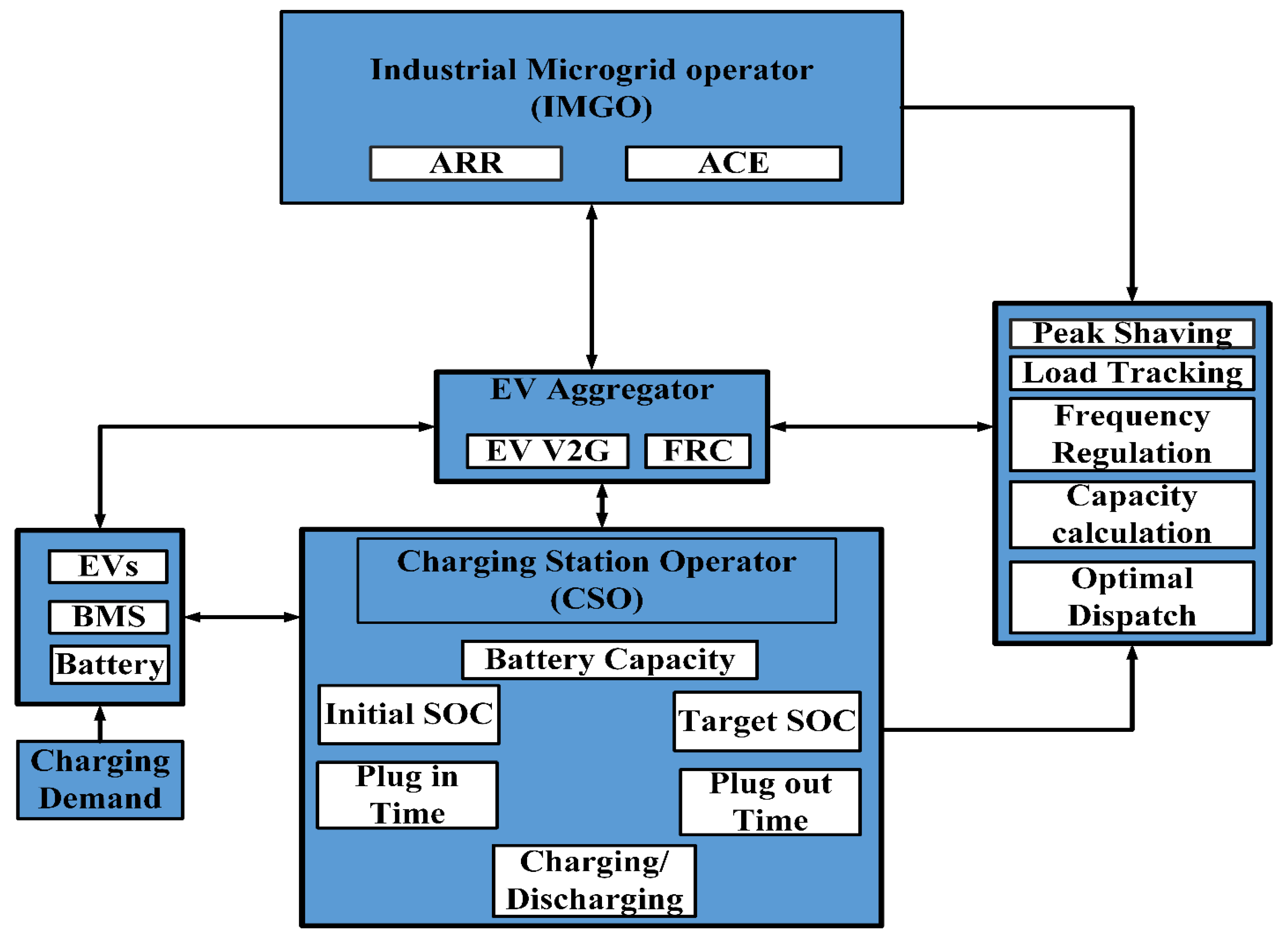
The article presents a novel primary frequency control through V2G strategy in an IMG, involving effective coordination of CSO, the EV aggregator, and the EV operator. A systematic structure incorporating the EV aggregator, EVs, and CSO is developed to ensure the PFC.
2)
The performance of the MG in the PFC is investigated with the same SOC levels of EVs that have been presented in the literature; however, different power charging/discharging demands of EVs are not acknowledged properly by previous works. Therefore, the EV charging power based on the departure time, the real-time battery SOC level, and the expected SOC is recalculated at each step and then adjusted in real-time. This operation is done with the effective role of the CSO.
3)
The main components of this novel V2G strategy are the industrial microgrid operator (IMGO), the EV aggregator, the CSO, and the EVs themselves. The concept of CSO is introduced, which coordinates with the electric vehicles aggregator (EVA) and accordingly charges and discharges the EVs.
4)
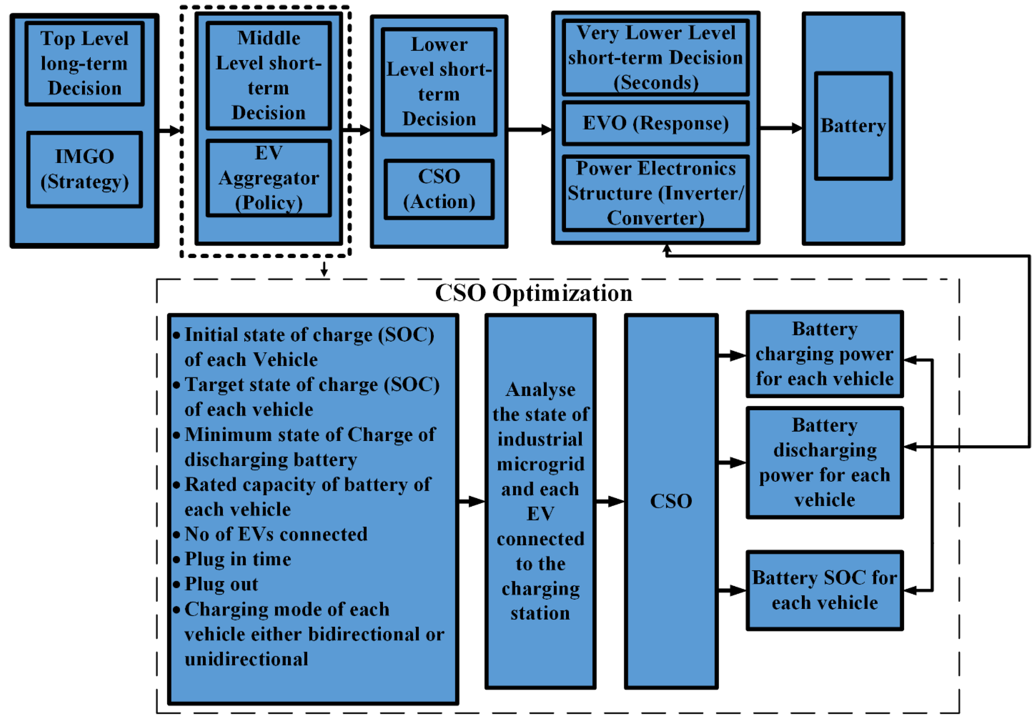
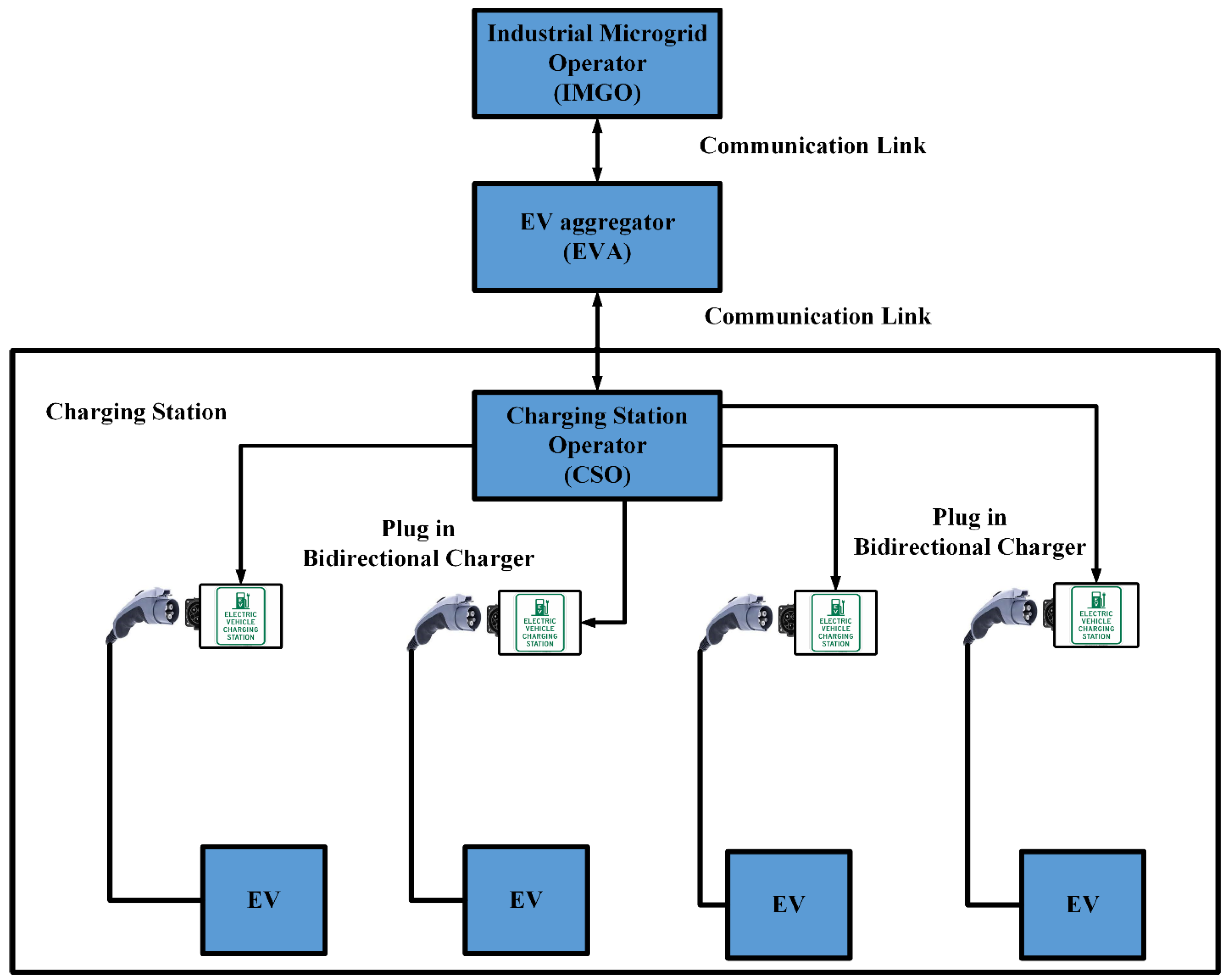
The CSO collects the data, analyses it, and solves the optimization function periodically. When an EV is parked and connected to the charging point at the charging station (CS), the record maintenance is ensured, with regards to EV’s state of charge, arrival, and departure time, number of EVs on the chagrining/discharging mode. The recharging socket outlet records the connection time and collects information from the EVA in order to solve the issue regarding the connection or disconnection of a new EV.
The current manuscript is organized as follows: Section 2 elaborates the derivation of the proposed hierarchical V2G framework for PFC through EV participation and Section 3 elucidates the proposed charging strategy for CSOs and their coordination and communication with EV aggregators and EVs. In Section 4, V2G control strategy rooted in frequency up-and-down regulation is presented and Section 5 introduces the simulation model and the corresponding results achieved, while Section 6 presents the results and discussion on the implications of the results. In Section 7, conclusions are drawn from the whole research endeavor.

2. Proposed Architecture

The prime objective of EVs when utilized for PFC in IMGs is to regulate their charging and discharging based on the IMG operator signals. Consequently, the following factors pertaining to V2G models are worth noting, as shown in Figure 1:
a)
In general operation, the performance of the generating section of IMGs is consistently monitored, controlled, and counterbalanced, as per the IMG operator signals. On the other hand, the capacity of power for a single EV can be ignored. Thus, the function of the EV aggregator is that of a middleman, providing a link between EVs and IMGs.
b)
Similar to the power generation units, the frequency regulation capacity (FRC) of the EVs should also be consistently monitored for correct dispatch of IMG operator signals to EVs. This means that the electric vehicles aggregator (EVA) is also responsible for FRC estimation and regulation tasks assigned by IMGs to EVs.
c)
The centralized charging/discharging of aggregated EVs performs the task of PFC at the industrial microgrid through the charging station operator. The control signal for charging and discharging of EVs is dispatched from the IMG operator, as per the voltage and frequency levels of the industrial microgrid. The EV aggregator transmits a signal to the CSO for action. The IMG operator provides all or part of the charging power without compromising the smooth operation of the IMG. The discharging operation is commenced once a fluctuation of voltage or frequency exceeds the acceptable level.
d)
The EV aggregator controls and manages the IMG operation, sending a signal to the CSO to charge or discharge the vehicles immediately or according to a schedule.
e)
The EVs, unlike the power generating sources, should be left with adequately high SOC for the primary operation of transportation.
FRC and V2G power were taken as the main factors in the control strategy for V2G. Once the CSO received a frequency regulation signal from EVA, it transmitted a signal to EVs, conforming to the proposed control strategy for V2G.

Objectives of V2G Control

For the purpose of frequency regulation, the EVs can be assumed to be analogous to mobile electricity storage devices. Accordingly, the control objective of the V2G strategy for EVs participating in PFC in IMGs is to properly undertake regulation tasks. Conversely, the use of EVs for their primary purpose of transportation inflicts some limitation on their use in PFC. A customer’s charging/discharging decisions, in addition to the SOC of EVs, are also preconditioned on the electricity prices, which are in turn dictated by the time of day. Hence, the second control objective of the V2G strategy would be the fulfillment of the customer’s requirements.

3. Charging and Discharging Strategy of CSO

Managing the recharging of EVs having disparate capacities can result in an optimum schedule operation as compared with unmanaged charging, which can induce problems in IMGs ranging from increased power losses and voltage and frequency imbalance to industrial equipment overload, such as cables and transformers. In severe cases, such as when recharging demand exceeds network power supply, it may lead to a complete black out of the IMG. In case of multiple charging stations in a distribution grid, each of them should take cue from the industrial microgrid operator (IMGO) and EVA and then manage the connected EVs.

CSO Synchronization with the EV Aggregator and EVs

The charging station system (CSS), being one of the two charging points for customers besides their homes, is a perfect spot for monitoring charging/discharging aggregated EVs. Hence, the main job of CSO is managing the charging resources for the customer as per their required SOC before they commence their journey. Accordingly, the CSO could either minimize the charging cost or maximize the discharging cost for the customer. Figure 2 presents a schematic outline of the aggregated EVs connected to the IMGs and the EVs to the CSO.
To ensure a smooth operation, the CSO should keep a ledger of all the EVs connecting or disconnecting each minute and perform a calculation. Hence, the CSO’s main function consists of three tasks: collect data, analyze data, and solve the optimization problem at regular intervals, e.g., minute-by-minute. The connection of the EV at the CS initiates the collection of the following information, also given in Figure 3.
  • Initial battery SOC,
  • Desired battery SOC,
  • Battery rated capacity,
  • EV parking time estimation,
  • Owner’s obligation of uni- or bi-directional power flow
  • Vehicle converter’s power limit
  • EV label for generating the bill

4. V2G Strategy for Primary Frequency Control

The proposed system for EV-based PFC is schematically represented in Figure 4.
The CSO can then work in one of the following two ways:
Method 1 G2V: If Pnet > 0, the EV operates in a charging manner.
Method 2 V2G: If Pnet < 0, the EV operates in a discharging manner.
Moreover, Pnet = PsPd; (total power = supply power − demand power)
The batteries of the EV underwent rapid discharge when Pnet < 0, causing a sharp fluctuation in voltage or frequency. Consequently, the objective function for the two methods was based on either the EVs’ charging method or the EVs’ discharging method. The EVA marked the EV and computed a solution for the objective function problem at set intervals to reserve slots for EV charging/discharging. Subsequently, the required power was dispatched to the CSO for EV charging, as per the EVA instruction and based on the existing power available for discharge from the vehicles to the IMG. Based on the statistics received from different portions of the IMG, the IMGO covered the charging station demand, in part or in full, and passed the surplus power to the EV. EVA then passed the signal to the CSO as per the IMGO signal, covering either part or the whole of the demand of the CSS. This enabled the CSS to develop a strategy for EV charging.
The EVA utilized the objective function to achieve the lowest possible cost in the charging mode. The charging scheme was dependent on the voltage and frequency limits. Time management in smart charging activated when the voltage limit was either at a voltage above minimal or a voltage over above minimal. Similarly, time management was triggered for frequency above minimal or frequency over above minimal. The charging was curtailed when the frequency was below minimal or frequency over below minimal. All these scenarios are delineated in Table 1.
In a discharging situation, the information was passed from the IMGO to the EVA to disconnect the EV. Following this, the EVA signaled the CSO to arrange the EV for discharge power, as per the standard charge limit.

4.1. Impact of CSO on the V2G Strategy

The CSO had a greater significance on the V2G operation of EVs. It comprised of bidirectional charging apparatus, a communication system, and an electricity meter. The bidirectional charges allowed power flow in two directions, i.e., from the EV to the IMG and from the IMG to the EV. Additionally, it also accounted for the power consumed and dispatched by the EV in charging and discharging, respectively. It also recorded the state of charge of the EVs. The CSO communication system then exchanged this information to the EVA.
The FRC of local EVs was also computed by the CSO. The V2G power was dispatched while monitoring the real time SOC of the battery until the desired level of SOC was reached. A power electronic system was employed, specifically minted for dealing with the charging/discharging equipment and the information management systems of EVs. A conceptual background of the V2G strategy is given in Figure 4.
The various steps involved in the mathematical system modeling are given in the following.

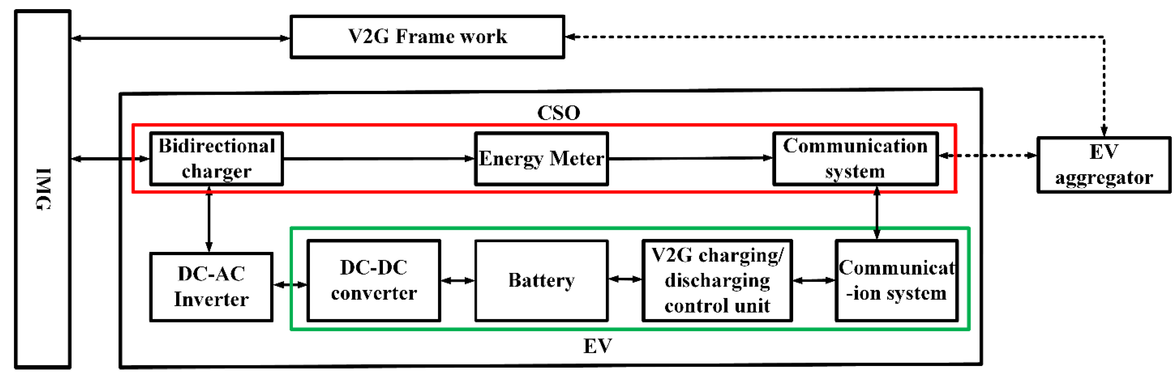
4.1.1. Concept of Electric Vehicle to Grid Power (EV2G)

The charging of electric vehicles was accomplished in two levels: first, the battery SOC was maintained and second its energy level was adjusted. As a result, these two levels should be incorporated in V2G power calculation, as shown in Equation (1). An example of this was, when at plug in time, the initial level of SOC was deemed adequate by the customer, who choose to maintain the SOC level. In such instances, a coordination method is proposed to efficaciously utilize EVs in the PFC process. The SOC level of the battery was thus maintained in the manner elaborated through Figure 5.
{ P j , k + 1 U p , 1 = i = 1 N j 1 ( P max . k i , k U p ) P j , k + 1 D o w n , 1 = i = 1 N j 1 ( P max . k i , k D o w n ) ( j = 1 , . p )
Two scenarios are pertinent to mention in Figure 5. Firstly, if the battery of the SOC was initially greater than the real-time SOC, the V2G power for up-regulation was greater than that for down-regulation, mainly because maintaining the SOC of the battery in such circumstances requires battery operation in the discharging mode. Conversely, if the initial SOC was less than the real-time SOC, the V2G power for up-regulation was less than that for down-regulation. In such a case, the power calculation for the increasing energy level of the battery was different from that described in Figure 5. A new principle, as depicted in Figure 6, dictated the charging/discharging power of the EV, where it was distributed into the regulation dispatch expectation and charging schedule of the EV for the continual charging demand.

4.1.2. Estimation of FRC

The FRC calculation holds great significance for EVs employed in PFC. The value of the FRC in such cases changes according to the real-time changes in charging/discharging power. Thus, the value of the upcoming time slot was based on the value of the existing time slot, as given in Equation (2) below.
{ S j , k + 1 D o w n , 1 = i = 1 N j ( P max P i , k ) S j , k + 1 U p , 1 = i = 1 N j ( P max + P i , k ) ( j = 1 , . p )

4.1.3. Assessment of EV2G Power

The SOC estimation for EV batteries maintenance, as per the concept illustrated in Figure 5, is given by the equations below.
{ P j , k + 1 U p , 1 = i = 1 N j 1 ( P max . K i , k U p ) P j , k + 1 D o w n , 1 = i = 1 N j 1 ( P max . K i , k D o w n ) ( j = 1 , . p )
where K i , k U p and K i , k D o w n are determined as follows:
If S O C i , k S O C i min
{ K i , k D o w n = 1 K i , k U p = 0
If S O C i , k S O C i max
{ K i , k D o w n = 0 K i , k U p = 1
If S O C i min < S O C i , k S O C i i n
{ K i , k D o w n = 1 2 ( 1 + S O C i , k S O C i i n S O C i min S O C i i n ) K i , k U p = 1 2 ( 1 S O C i , k S O C i i n S O C i min S O C i i n )
If S O C i i n < S O C i , k S O C i max
{ K i , k D o w n = 1 2 ( 1 S O C i , k S O C i i n S O C i max S O C i i n ) K i , k U p = 1 2 ( 1 + S O C i , k S O C i i n S O C i max S O C i i n )
This means that the up-and-down regulation demonstrated a negative correlation dependent on the SOC of battery, in line with the principle given in Figure 5.

4.1.4. The Correlation Between EVs and EV2G Power

P j , k + 1 D o w n , 1 + P j , k + 1 U p , 1 = P max

4.1.5. Aggregated EV2G Power for the Charging Station

The total power requirement of V2G at each charging station for EVs can be calculated as below.
{ P j , k + 1 U p , 1 = P j , k + 1 U p , 1 + P j , k + 1 U p , 2 P j , k + 1 D o w n , 1 = P j , k + 1 D o w n , 1 + P j , k + 1 D o w n , 2 ( j = 1 , . p )

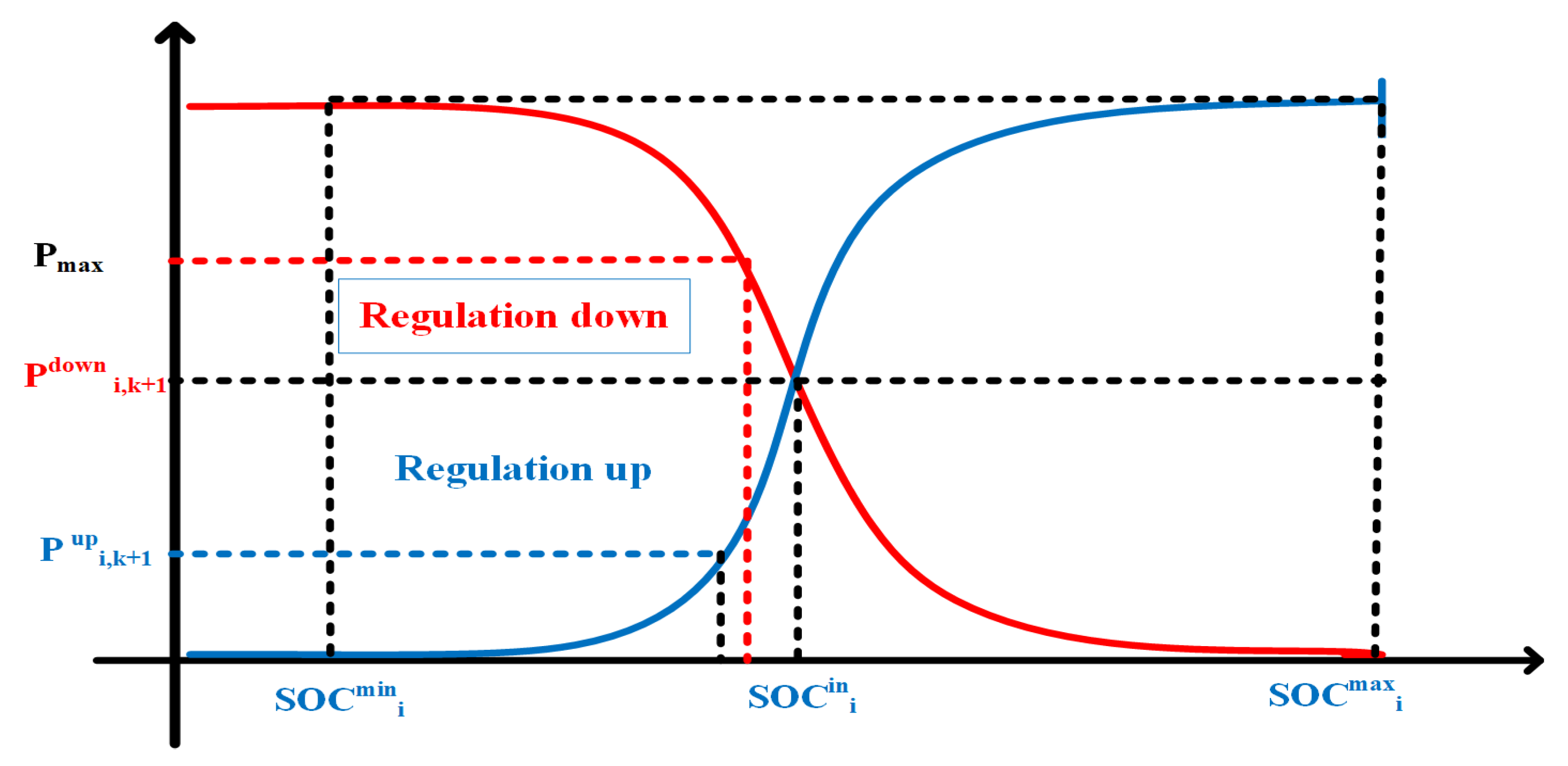
4.1.6. V2G Strategy of EV Battery SOC Levels

Maintaining EV battery SOC levels, the total FRC is a function of the charging stations for EVs. The CSO received a frequency regulation signal from the EVA. A group of EVs were then assigned the frequency regulation tasks, as per their SOC levels.
S j , k + 1 1 = { S j , k + 1 s P j , k + 1 U p , 1 ( P j , k + 1 U p , 1 + P j , k + 1 U p , 2 )     ( S j , k + 1 s 0 ) S j , k + 1 s P j , k + 1 D o w n , 1 ( P j , k + 1 D o w n , 1 + P j , k + 1 D o w n , 2 )     ( S j , k + 1 s 0 )
The regulation operation was distributed proportionally, as dictated by the EV2G power coming from the two kinds of EVs at k + 1 time. Following the regulation task assignment by Equation (11), a command was sent to each vehicle by the V2G controller in the EV charging station. The V2G regulation power at instant k + 1 was governed proportionally for each EV, maintaining the SOC level through the following strategy:
P i , k + 1 = { S j , k + 1 1 η d P j , k + 1 U p , 1 i = 1 N j 1 ( P j , k + 1 U p , 1 )     ( S j , k + 1 s 0 ) S j , k + 1 1 . η c P j , k + 1 D o w n , 1 i = 1 N j 1 ( P j , k + 1 D o w n , 1 )     ( S j , k + 1 s 0 )

4.2. EV Aggregator V2G Control Strategies

4.2.1. Purpose of Frequency Regulation Capacity

The total FRC for the EVA is summarized in the following equation:
{ S k + 1 U p , 1 = j = 1 p S j , k + 1 U p S k + 1 D o w n , 1 = j = 1 p S j . k + 1 D o w n

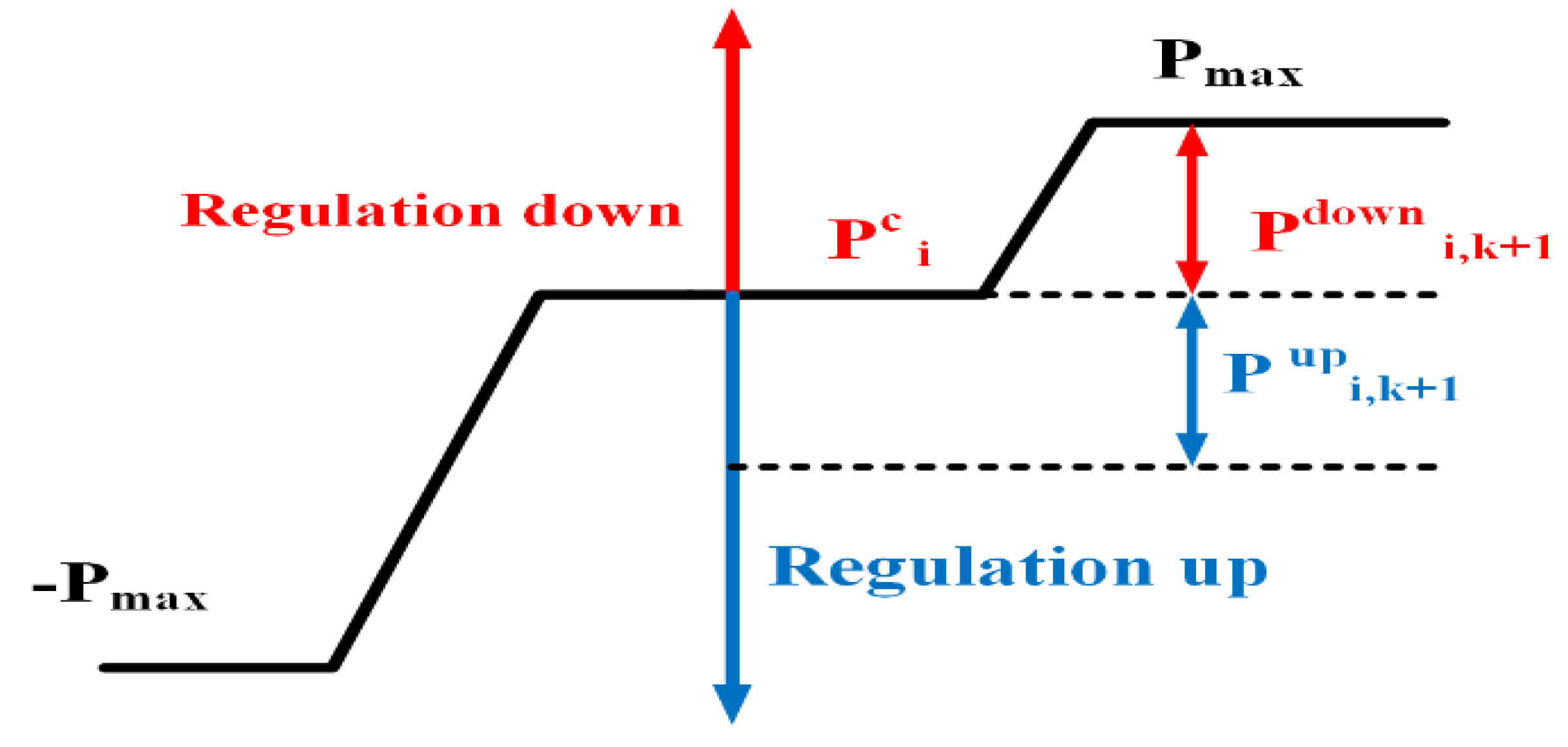
4.2.2. Total EV2G Power

The total EV2G power and the EV2G power uploaded by CSO is given as follows:
{ P k + 1 U p , 1 = j = 1 p P j , k + 1 U p P k + 1 D o w n , 1 = j = 1 p P j , k + 1 D o w n

4.2.3. V2G Control Framework to Eliminate the Area Control Error (ACE)

Area control error (ACE) reduction is generally considered as a PFC control objective. The EVs and generating units involved in PFR respond to regulation signals, resulting in ACE fluctuation once the ACE exceeds the dead band. Here, the EV user requirements and regulations are the major determinants of the V2G control strategies through a coordinated process proposed in the following:
{ f ( x ) = x 2 x 2 + y 2 x + y = C
where x represents the up-regulation, while y represents the down regulation, whereas C is the constant resulting from EV2G power.

5. System Modelling and Simulation

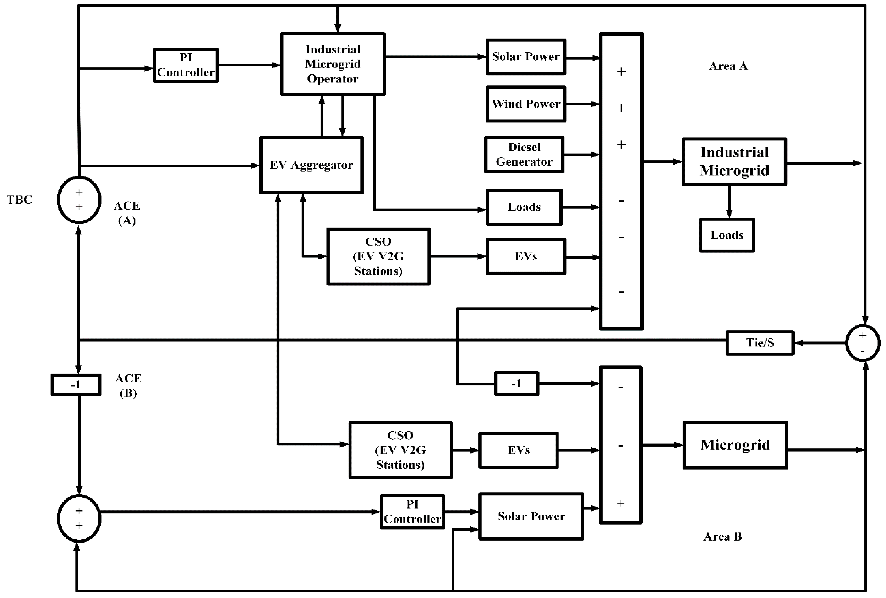
5.1. Interconnected Industrial Microgrid and Microgrid

The two-area power network model was designed using practically interconnected IMGs and microgrid operational data. Tie-line bias control was used for area A, while flat tie-line control was employed for area B, considering the practical interconnected mode. The main concerns lay in area A, where the EV, solar, and wind power were integrated into the IMG, as exhibited in the Figure 7. A percentage of maximum load capacity, usually up to 5%, was reserved for regulation control through the governor. In case of interconnected IMGs and microgrids, tie-line bias control [24] was employed. This meant that the area control error, ACE, IMGO = ∆Pt + B.∆f, and ACE = ∆Pt was considered in the load frequency control. The random load in time series, consisting of slow base components with large amplitude and fast fringe components with comparatively smaller amplitude, was utilized for simulation of frequency regulation, as shown in Figure 8. The intermittent nature of wind power is graphically represented in Figure 9, while that of PV is presented in Figure 10. Both the graphs were formed from real historical data. The parameters of the IMG are detailed in Table 2.
In area A, 20 generating units, out of the 50 controlled by IMGO, took part in PFC. The remaining 30 generating units followed a business-as-usual plan. A stable supply–demand mechanism was assumed in area B, thus, the frequency fluctuation here was only influenced by the supply–demand mismatch in area A through the power oscillation in the tie-line. As shown in the Figure 6, in the “IMGO strategies” block, a practical industrial and microgrid control strategy was employed for the power dispatch to generating units. The basic simulation parameters are detailed in Table 2.

5.2. V2G Simulation Model

The battery’s SOC at that time can be written as [22]:
S O C i , k = S O C i i n + 1 E i r Δ E i
where Δ E i denotes the battery energy variation during the charging/discharging process and satisfies:
S O C i , k = S O C i i n + 1 E i r Δ E i
Δ E i = 0 k P i ( k ) d k .
The V2G control was generally considered free from ramp rate restrictions relative to conventional generating units, as shown in Figure 11. This was largely because of the fast regulation and response feature of EVs. As shown in the system framework in Section 4.2, EVs take part in PFC through an EV aggregator and two EV charging stations. The charging behavior of the EV users is generally attributed to two key features: maintaining and adjusting battery SOC levels, as stated in Section 3. These two behavioral traits are generally deemed as TYPE 1 and TYPE 2.
The simulation parameters for the V2G simulation employed in the proposed strategy are delineated in Table 3.

6. Results and Discussions

6.1. Simulation Scenarios

Since EV customers were random in terms of their frequency and time spent at charging stations, the current research assumed normally distributed scenarios encompassed by the up and down limit for description of battery SOC levels. Subsequently, for verification of the proposed strategy, two-area interconnected microgrid and IMG, as shown in the Figure 7, were considered. The IMG parameters are further described in Table 2. Four different charging station profiles, each possessing a CS, IMG, and MG, were considered in detail in the following.
Scenario 1: Working hours of 08:00–16:00, close to the IMG site, and using the workplace charging station. This scenario makes up 30% of the total EVs.
Scenario 2: Working hours from 08:00–16:00, with 2 h of commute to and from workplace and using the IMG charging station. This scenario makes up 40% of the EVs.
Scenario 3: Consists of people not using their EVs during the day, who are consistently connected to the IMG for 24 h. This scenario represents 20% of the EVs.
Scenario 4: Consists of people working from 22:00–04:00, with 30 min commute to and from work, and a charging station at workplace. This scenario represents 10% of the EVs.

6.2. Simulation Description and Different Scenarios

For each of the scenarios mentioned in the previous section, the V2G control strategy was implemented. Figure 12 and Figure 13 show random SOC data of four EVs. Similar curves were obtained for the four EVs, accruing from similar strategies. The fast adjustments in the charging/discharging behavior of EVs resulted in suppression of frequency fluctuation and ACE. Furthermore, the effectiveness of V2G strategy for maintaining SOC levels is evident from Figure 12a and Figure 13a. The charging curves in Figure 12b and Figure 13b suggest that V2G strategy was also effective for achieving the required SOC levels. This was due to the V2G strategy enabling performance of up-regulation and down-regulation tasks to be dynamically coordinated as per the SOC levels of battery, as shown in Figure 14. The suppression of ACE due to generating units and EVs is demonstrated through the curves in Figure 15 and Figure 16, where the ACE, with and without V2G strategy application, is given in Figure 15. The total contribution of power generating units and the total FRC and V2G power are illustrated in Figure 16. It is evident from these curves that the implementation of V2G strategy offset the regulation responsibility from the generating units to EVs in PFC. The up-regulation and down-regulation FRCs in Figure 16 were dynamically retained at specific levels.
The total load comprised of an asynchronous motor simulating inductive industrial load, office load, and a domestic residential load, powering 800 households. The residential load carried a specific consumption signature with a power factor. The Monte Carlo sampling strategy was utilized for achieving a normally distributed battery SOC in case of each EV and then simulated in Simulink.

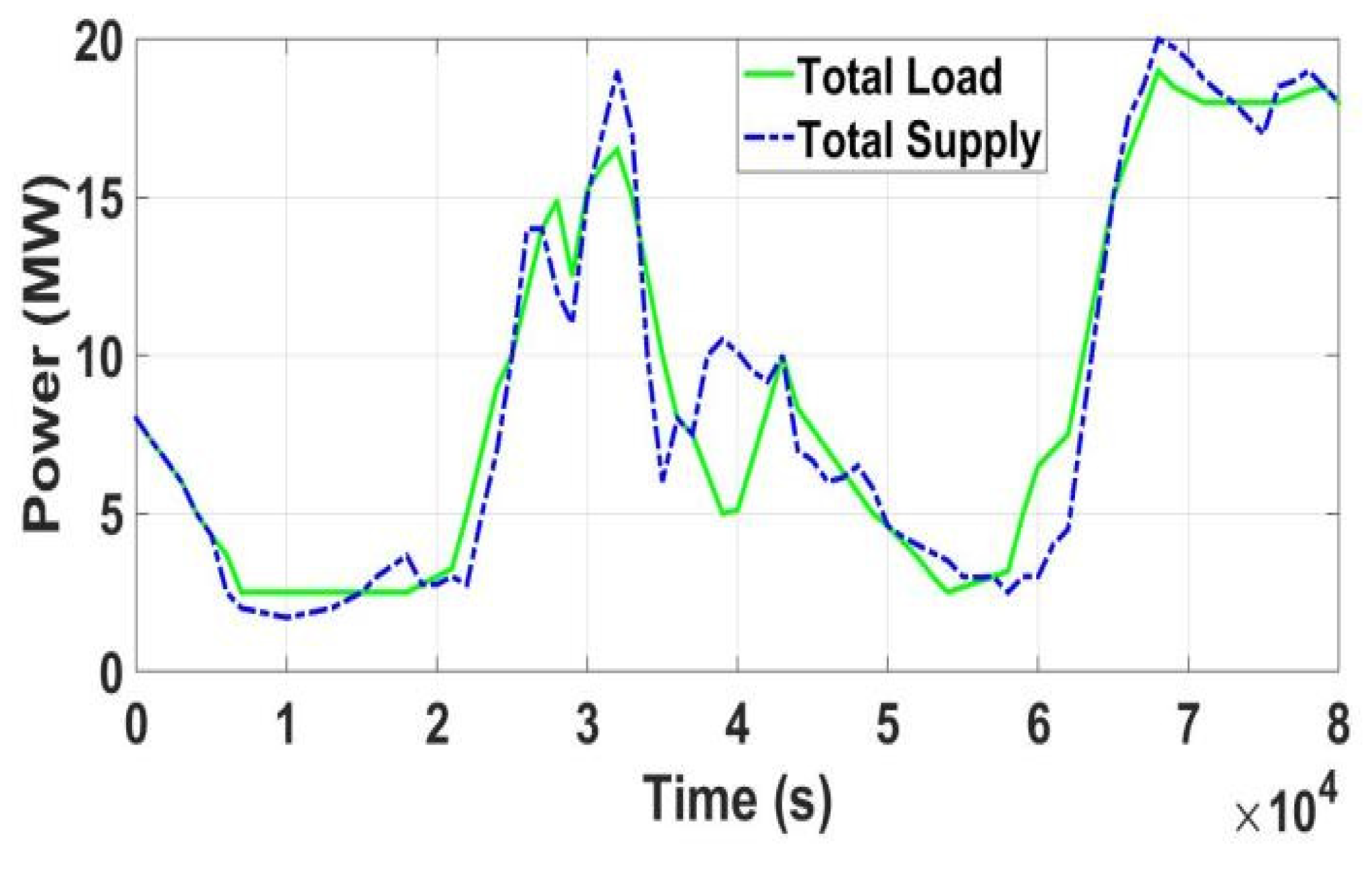
6.3. Influences of V2G on the Industrial Microgrid

The assimilation of EVs in the IMGs solely impacted the generating unit’s power output in the context of PFC. This was mainly due to the EVs and generating units taking a combined responsibility for PFC. In cases where PFC responded to deviations in system frequency, there was also a slight influence on the output of generating units not directly participating in PFC. This impact of V2G on IMG is evident in Figure 17, where the PFC pre-and-post V2G implementation is demonstrated through frequency fluctuations in the recorded time interval.
A total of 40 EVs had a considerable effect on stabilizing the frequency fluctuations in IMGs, whereas 30 EVs also impacted the situation positively. This significantly reduced the load on the IMG in peak hours, where the generation-load imbalance caused considerable fluctuations in frequency, especially from 10:00–14:00, as shown in Figure 8, within interval between 3–4. In the off-peak hours, the same EVs acted as a load to stabilize the IMG voltage.

7. Conclusions

The main emphasis of the research article was to develop a novel V2G control scheme for electric vehicle participation in the primary frequency control (PFC). Accordingly, a systematic structure incorporating an EV aggregator, EVs, and CSO was developed to ensure PFC. The proposed V2G strategy provided a precious resource of primary frequency regulations in IMGs through active participation of EVs. The main components of this novel V2G strategy were IMGO, the EV aggregator, CSO, and the EVs themselves. The concept of CSO was introduced, which coordinated with EVA and accordingly charged and discharged the EVs. The EV aggregator covered two aspects in PFC: first, to estimate the FRC and EV2G power available from all EVs and then to implement the V2G strategy for dispatching regulation requirements to the individual EVs. Keeping in view the ACE, FRC, and EV2G power, a V2G was successfully developed and validated using simulations for frequency regulation and charging demands. The strategy employed FRC calculation at EV charging stations, factoring in the V2G power at the present time. Furthermore, V2G regulation strategies for EV charging stations for distribution of regulation tasks to EVs were also developed. The CSO assigned frequency regulation capacity (FRC) to the electric vehicles and enabled the bi-directionality of power flow in real-time. The V2G control model was validated through simulations based on two-area interconnected industrial microgrids and a microgrid model, which indicated a noticeable improvement in the primary frequency and ACE fluctuations, mainly accruing from the V2G strategy. The strategy also had the additional benefit of ensuring SOC levels of EV batteries.
Future Work: In the future, the authors will conduct a comparative study with a centralized V2G system to evaluate the validity of the proposed system in detail, while considering aspects of communication, computation cost, and performance during frequency regulation. Furthermore, impact of stochastic communication failure on the performance of the proposed system will be assessed.

Author Contributions

Conceptualization, S.I.; methodology, S.I. and A.X.; software, S.I. and A.u.M.Z.; validation, S.S.; formal analysis, M.U.J.; investigation, H.U.R. and M.F.S.; resources, A.X.; data curation, S.S. and M.A.A.; writing—Original draft preparation, S.I.; writing—Review and editing, A.X., M.U.J., A.u.M.Z., and M.A.A.; visualization, H.U.R. and M.F.S.; supervision, A.X.; project administration, A.X.; funding acquisition, A.X. All authors have read and agreed to the published version of the manuscript.

Funding

This work was supported by the 2016 national key R&D program of China to support the low-carbon Winter Olympics of the integrated smart grid demonstration project (2016YFB0900500) and Beijing Natural Science Foundation (3182037). The Fundamental Research Funds for the Central Universities under Grant 2019QN041.

Conflicts of Interest

The authors declare no conflict of interest.

Nomenclature

B Frequency bias factor
Δ f Frequency deviation
Δ E i Energy variation of the ith EV battery
E i r Rated capacity of the ith EV battery
P max Maximum V2G power at the battery side of EVs
P i , k + 1 V2G power at the battery side of the ith EV at time k + 1
S j , k + 1 D o w n Regulation-down FRC of the jth EV charging station at time k + 1
S j , k + 1 U p Regulation-up FRC of the jth EV charging station at time k
S O C i max Maximum SOC of the ith EV
S O C i min Minimum SOC of the ith EV
S O C i , k SOC of the ith EV battery at time k .
S O C i i n Initial SOC of the ith EV at plug-in time
K i , k U p Up-regulation factor
K i , k D o w n Down-regulation factor
N j 1 Number of EVs in the jth EV charging station for maintaining battery SOC levels
N j 2 Number of EVs in the jth EV charging station adjusting battery SOC levels.
P j , k + 1 D o w n , 1 EV2G power of EVs holding battery SOC levels of the jth EV charging station at time k + 1 for down-regulation
P j , k + 1 U p , 1 EV2G power of EVs holding battery SOC levels of the jth EV charging station at time k + 1 for up-regulation
P j , k + 1 U p , 2   EV2G power of EV adjusting battery SOC levels of the jth EV charging station at time k + 1 for up-regulation
P j , k + 1 D o w n , 2 EV2G power of EV adjusting battery SOC levels of the jth EV charging station at time k + 1 for down-regulation
S j , k + 1 1 Regulation task of the jth EV charging station at time k + 1 for maintaining battery energy
S j , k + 1 2 Regulation task of the jth EV charging station at time k + 1 for adjusting battery SOC levels
S j , k + 1 s Regulation task of the jth EV charging station at time k + 1
P i , k + 1 V2G power at the battery side of the ith EV at time k + 1
η d Discharging efficiency of EVs
η c Charging efficiency of EVs

Abbreviations

SOCState of charge
PFCPrimary frequency control
FRCFrequency regulation capacity
ACEArea control error
ARRArea regulation requirement
IMGOIndustrial microgrid operator
CSOCharging station operator
EVOElectric vehicle operator
EVAElectric vehicle aggregator
EVV2GElectric vehicle-vehicle to grid
RERRenewable energy resources
DGsDistributed generations
DGRsDistributed generations resources
CSSCharging station system
LFCLoad frequency control

References

  1. Fan, Y.V.; Perry, S.; Klemeš, J.J.; Lee, C.T. A review on air emissions assessment: Transportation. J. Clean. Prod. 2018, 194, 673–684. [Google Scholar] [CrossRef]
  2. Nykvist, B.; Sprei, F.; Nilsson, M. Assessing the progress toward lower priced long range battery electric vehicles. Energy Policy 2019, 124, 144–155. [Google Scholar] [CrossRef]
  3. Li, H.; Eseye, A.T.; Zhang, J.; Zheng, D. Optimal energy management for industrial microgrids with high-penetration renewables. Prot. Control Mod. Power Syst. 2017, 2, 12. [Google Scholar] [CrossRef] [Green Version]
  4. Li, Y.; Feng, B.; Li, G.; Qi, J.; Zhao, D.; Mu, Y. Optimal distributed generation planning in active distribution networks considering integration of energy storage. Appl. Energy 2018, 210, 1073–1081. [Google Scholar] [CrossRef] [Green Version]
  5. Liu, H.; Hu, Z.; Song, Y.; Wang, J.; Xie, X. Vehicle-to-grid control for supplementary frequency regulation considering charging demands. IEEE Trans. Power Syst. 2014, 30, 3110–3119. [Google Scholar] [CrossRef]
  6. Bayati, M.; Abedi, M.; Gharehpetian, G.B.; Farahmandrad, M. Short-term interaction between electric vehicles and microgrid in decentralized vehicle-to-grid control methods. Prot. Control Mod. Power Syst. 2019, 4, 1–11. [Google Scholar] [CrossRef] [Green Version]
  7. Shafie-khah, M.; Siano, P.; Aghaei, J.; Masoum, M.A.; Li, F.; Catalão, J.P. Comprehensive review of the recent advances in industrial and commercial DR. IEEE Trans. Power Syst. 2019, 15, 3757–3771. [Google Scholar] [CrossRef]
  8. Rizvi, S.A.A.; Xin, A.; Masood, A.; Iqbal, S.; Jan, M.U.; Rehman, H. Electric Vehicles and their Impacts on Integration into Power Grid: A Review. In Proceedings of the 2nd IEEE Conference on Energy Internet and Energy System Integration (EI2), Beijing, China, 20–22 October 2018; pp. 1–6. [Google Scholar]
  9. Liu, H.; Huang, K.; Wang, N.; Qi, J.; Wu, Q.; Ma, S.; Li, C. Optimal dispatch for participation of electric vehicles in frequency regulation based on area control error and area regulation requirement. Appl. Energy 2019, 240, 46–55. [Google Scholar] [CrossRef]
  10. Meng, J.; Mu, Y.; Jia, H.; Wu, J.; Yu, X.; Qu, B. Dynamic frequency response from electric vehicles considering travelling behavior in the Great Britain power system. Appl. Energy 2016, 162, 966–979. [Google Scholar] [CrossRef]
  11. Zhang, Q.; Li, Y.; Li, C.; Li, C.-Y. Real-time adjustment of load frequency control based on controllable energy of electric vehicles. Trans. Inst. Meas. Control 2020, 42, 42–54. [Google Scholar] [CrossRef]
  12. Shakerighadi, B.; Anvari-Moghaddam, A.; Ebrahimzadeh, E.; Blaabjerg, F.; Bak, C.L. A hierarchical game theoretical approach for energy management of electric vehicles and charging stations in smart grids. IEEE Access 2018, 6, 67223–67234. [Google Scholar] [CrossRef]
  13. Bevrani, H.; Shokoohi, S. An intelligent droop control for simultaneous voltage and frequency regulation in islanded microgrids. IEEE Trans. Smart Grid 2013, 4, 1505–1513. [Google Scholar] [CrossRef]
  14. Iqbal, S.; Xin, A.; Jan, M.U.; Ur Rehman, H.; Masood, A.; Rizvi, S.A.A.; Salman, S. Aggregated Electric Vehicle-to-Grid for Primary Frequency Control in a Microgrid-A Review. In Proceedings of the IEEE 2nd International Electrical and Energy Conference (CIEEC), Beijing, China, 4–7 November 2018; pp. 563–568. [Google Scholar]
  15. Liu, H.; Qi, J.; Wang, J.; Li, P.; Li, C.; Wei, H. EV dispatch control for supplementary frequency regulation considering the expectation of EV owners. IEEE Trans. Smart Grid 2016, 9, 3763–3772. [Google Scholar] [CrossRef] [Green Version]
  16. Li, Y.; Zhang, Q.; Li, C.; Li, C. Real-Time Adjustment of Load Frequency Control Based on Controllable Energy of Electric Vehicles. In Advances in Green Energy Systems and Smart Grid; Springer: Berlin/Heidelberg, Germany, 2018; pp. 105–115. [Google Scholar]
  17. Habib, S.; Kamran, M.; Rashid, U. Impact analysis of vehicle-to-grid technology and charging strategies of electric vehicles on distribution networks–a review. J. Power Sources 2015, 277, 205–214. [Google Scholar] [CrossRef]
  18. Liu, H.; Yang, Y.; Qi, J.; Li, J.; Wei, H.; Li, P. Frequency droop control with scheduled charging of electric vehicles. IET Gener. Transm. Distrib. 2017, 11, 649–656. [Google Scholar] [CrossRef]
  19. Zhu, X.; Xia, M.; Chiang, H.-D. Coordinated sectional droop charging control for EV aggregator enhancing frequency stability of microgrid with high penetration of renewable energy sources. Appl. Energy 2018, 210, 936–943. [Google Scholar] [CrossRef]
  20. Kafle, L.; Ni, Z.; Tonkoski, R.; Qiao, Q. Frequency control of isolated micro-grid using a droop control approach. In Proceedings of the IEEE International Conference on Electro Information Technology (EIT), Grand Forks, ND, USA, 19–21 May 2016; pp. 0771–0775. [Google Scholar]
  21. Kaur, K.; Singh, M.; Kumar, N. Multiobjective optimization for frequency support using electric vehicles: An aggregator-based hierarchical control mechanism. IEEE Syst. J. 2017, 13, 771–782. [Google Scholar] [CrossRef]
  22. Karfopoulos, E.L.; Panourgias, K.A.; Hatziargyriou, N.D. Distributed coordination of electric vehicles providing V2G regulation services. IEEE Trans. Power Syst. 2015, 31, 2834–2846. [Google Scholar] [CrossRef]
  23. Zhang, W.; Srinivasan, D.; Sharma, A. Comment on “Distributed Coordination of Electric Vehicles providing v2g Regulation Services” by el Karfopoulos, Ka Panourgias, N and D. hatziargyriou. In Proceedings of the IEEE Innovative Smart Grid Technologies-Asia (Isgt Asia), Singapore, 22–25 May 2018; pp. 456–458. [Google Scholar]
  24. Su, S.; Hu, Y.; Wang, S.; Wang, W.; Ota, Y.; Yamashita, K.; Xia, M.; Nie, X.; Chen, L.; Mao, X. Reactive power compensation using electric vehicles considering drivers’ reasons. IET Gener. Transm. Distrib. 2018, 12, 4407–4418. [Google Scholar] [CrossRef]
  25. Safari, A.; Babaei, F.; Farrokhifar, M. A load frequency control using a PSO-based ANN for micro-grids in the presence of electric vehicles. Int. J. Ambient Energy 2019, 1–13. [Google Scholar] [CrossRef]
  26. Chhaya, L.; Sharma, P.; Bhagwatikar, G.; Kumar, A. Wireless sensor network based smart grid communications: Cyber attacks, intrusion detection system and topology control. Electronics 2017, 6, 5. [Google Scholar] [CrossRef]
  27. Khooban, M.-H.; Niknam, T.; Shasadeghi, M.; Dragicevic, T.; Blaabjerg, F. Load frequency control in microgrids based on a stochastic noninteger controller. IEEE Trans. Sustain. Energy 2017, 9, 853–861. [Google Scholar] [CrossRef]
  28. Khooban, M.H.; Gheisarnejad, M. A Novel Deep Reinforcement Learning Controller Based Type-II Fuzzy System: Frequency Regulation in Microgrids. IEEE Trans. Emerg. Top. Comput. Intell. 2020, 1–11. [Google Scholar] [CrossRef]
Figure 1. Conceptual view of the vehicle to grid (V2G) strategy.
Electronics 09 00549 g001
Figure 2. Charging station operator optimization.
Electronics 09 00549 g002
Figure 3. Illustrative representation of the charging station operator (CSO).
Electronics 09 00549 g003
Figure 4. CSO and V2G framework for the primary frequency control (PFC) of an industrial microgrid.
Electronics 09 00549 g004
Figure 5. Expected state of charge (SOC) of the electric vehicles (EVs) battery, considering V2G power.
Electronics 09 00549 g005
Figure 6. Proposed V2G power of electric vehicles to regulate the battery SOC.
Electronics 09 00549 g006
Figure 7. Simulation network of industrial microgrid for the PFC with EVs.
Electronics 09 00549 g007
Figure 8. Hourly-based random load of industrial microgrid.
Electronics 09 00549 g008
Figure 9. Total output power of wind.
Electronics 09 00549 g009
Figure 10. Total output power of solar.
Electronics 09 00549 g010
Figure 11. V2G control for primary frequency regulation.
Electronics 09 00549 g011
Figure 12. Real-time battery state of charge for the four EVs under consideration for (a) TYPE 1, Charging Station 1 and (b) TYPE 2, Charging Station 1.
Electronics 09 00549 g012
Figure 13. Real-time battery state of charge for the four EVs under consideration for (a) TYPE 1, Charging Station 2 and (b) TYPE 2, Charging Station 2.
Electronics 09 00549 g013
Figure 14. Simulation of real-time coordination for up-regulation and down-regulation.
Electronics 09 00549 g014
Figure 15. Results of ACE and the pre-and-post V2G strategy application.
Electronics 09 00549 g015
Figure 16. EV V2G power and total frequency regulation capacity (FRC), resulting in ACE suppression.
Electronics 09 00549 g016
Figure 17. PFC of industrial microgrid without V2G and with V2G.
Electronics 09 00549 g017
Table 1. Nominal values of voltage and frequency.
S. NoTermRange
1 Minimal frequency 0.001 f m f 0.001 f m
2 Minimal voltage 0.03 V m V 0.03 V m
3 Frequency above minimal 0.001 f m f 0.01 f m Charging Reference
4 Frequency over above minimal 0.01 < f m < f
5 Voltage above minimal 0.03 V m V 0.1 V m
6 Voltage over above minimal 0.1 V m V
7 Frequency below minimal 0.001 f m f 0.01 f m Discharging Reference
8 Frequency over below minimal 0.01 f m < f
9 Voltage below minimal 0.03 V m V 0.1 V m
10 Voltage over below minimal 0.1 V m < V
11 f m = 50 H z w h e r e   as   the   V m = 220
Table 2. Two-area interconnected power grid.
Important ParametersArea AArea B
Proportional gain11
Integral gain0.010.01
Time constant for load frequency control (LFC) (s)44
Frequency bias factor (KW/01Hz)340
Inertia constant (KW. s)1632054720
Load damping coefficient (MW/Hz)20406840
Dead band of PFC (Hz)0.033
Communication delay (s)11
Dead band (DB) of area control error (ACE) (KW)2020
Time constant for wind fluctuation (s)11
Table 3. Simulation parameters of V2G.
ParametersCharging Station (CS-1)Charging Station (CS-2)
EV type-1EV type-2EV type-1EV type-2
Number of EVs15010017080
The number of EV aggregators2
Dispatching cycle (s)4
Communication delay (s)1
Charging/discharging efficiency0.92/0.92
Plug in time (s)Time~N (3600)
Plug out time (s)Time~N (7200)
Initial SOC at the plug-in time (pu)SOC~N (0.4, 0.1)
Expected SOC at the plug out time (pu)SOC [0.2,05]
SOC~N (0.7, 0.1)
Battery capacity (kwh)16
Maximum V2G power (KW)7
Maximum/minimum SOC limitation (pu)0.98/02

