Article

A Low-Profile Wideband Antenna for WWAN/LTE Applications

1
Dept. of Electrical and Computer Engineering, King Abdulaziz University, Jeddah 21589, Saudi Arabia
2
Dept. of Physics, University of Chittagong, Chittagong 4331, Bangladesh
3
Centre of Advanced Electronic and Communication Engineering, Universiti Kebangsaan Malaysia, Bangi 43600, Malaysia
*
Author to whom correspondence should be addressed.
Electronics 2020, 9(3), 393; https://doi.org/10.3390/electronics9030393
Submission received: 10 February 2020 / Revised: 14 February 2020 / Accepted: 25 February 2020 / Published: 27 February 2020
(This article belongs to the Section Microwave and Wireless Communications)

Abstract

:
In this paper, a low-profile antenna is presented for wideband communication applications. The presented design consists of an I-shaped driven strip and a rectangular ground strip with an open slot in the middle and a steeped lower portion. The measured results demonstrate that the achieved operating band of the proposed antenna has the potential to cover Globalstar satellite phones (GSSP) (1.61–1.63 GHz, uplink), advanced wireless systems (1.71–1.76 GHz, 2.11–2.17 GHz), DCS (1710–1880 MHz), GSM (1800MHz), DCP (1.88–1.90 GHz), DCS-1900/PCS/PHS (1850–1990MHz), WCDMA/IMT-2000 (1920–2170MHz), UMTS (1920–2170 MHz) and long-term evolution (LTE) bands (FDD LTE bands 1–4, 9–10, 15–16, 23–25, 33–37, 39). The designed antenna possessed a very small size of 0.35λ0 × 0.027λ0 at the lowest frequency (S11 ≤ −10dB), achieved good gains and exhibited stable radiation patterns, which makes it suitable for handheld communication devices.
Keywords:
antenna; BDR; LTE; wideband; WWAN

1. Introduction

The rapid advancement of mobile communication towards next generation communication systems requires multiband and wideband antennae that are able to cover different wireless and mobile services. The use of wideband antennae not only lessen the number of antennae necessary to cover different frequency bands, but also reduces the system complexity, overall device size, and costs. A cellular phone antenna for wireless wide area network (WWAN) operation is usually required to cover global systems for mobile communication (824–960 MHz), Globalstar satellite phones (GSSP) (1.61–1.63 GHz, uplink), advanced wireless systems (1.71–1.76 GHz, 2.11–2.17 GHz), DCS (1710–1880 MHz), GSM (1800MHz), digital cordless phones (1.88–1.90 GHz), DCS-1900/PCS/PHS (1850–1990MHz), WCDMA/IMT-2000 (1920–2170MHz) and UMTS (1920–2170 MHz), along with the recently introduced long-term evolution (LTE) bands; therefore, a handset antenna needs to cover all these bands. The role of wideband and multiband antennae has become more significant since the carrier aggression technique of the LTE communication system was released [1]. The volumetric size of the multiband and wideband antennae inside the portable communication devices must be as small as possible.
Various types of handset antennae have been reported to achieve a wide operating band. Slot antennae can exhibit multiple resonance modes, as well as being able to merge the nearby resonances, which result in the exhibition of wider bandwidths. However, wide-slot antennae sometimes require large areas which make them difficult to integrate within portable communication devices. To lessen the size of the multi-band/wideband antenna, a number of designs have been reported. For example, in [2], a compact antenna comprised of a U-shaped loop, a T-shaped slot and a feeding line is presented for handset applications. However, the designed antenna possesses a large volumetric size of 64.5 × 135 × 0.6 mm3. For mobile phone applications, in [3], a low-profile internal antenna with a volumetric size of 46 × 88.5 × 0.8 mm3 is reported. The presented antenna can exhibit dual operating bands ranging from 848 MHz to 1152 MHz and 1736 MHz to 3000 MHz. In [4], a loop antenna is presented for WWAN/LTE smartphone applications. The desired operation in DCS/PCS/UMTS2100/LTE2300/LTE2500 bands is achieved by the high-order modes of two loops. However, it requires a large system ground plane of 70 × 115 × 0.8 mm3. In [5], the design of an internal antenna is presented for WWAN/WLAN/ISM/LTE smartphone applications. The design is comprised of a meander loop and a capacitive coupled feedline and is able to exhibits dual bands of 712–1078 MHz and 1757–2930 MHz. However, its applications in many portable devices are restricted, due to its large dimension of 120 × 60 × 1.6 mm3. For LTE 13-band applications, in [6] a mobile handset MIMO antenna is presented. This design is comprised of two symmetrical inverted-F antennae in addition of a T-shaped patch. However, the reported design possesses a large footprint of 60 × 15 × 5 mm3 and can only support a 746–787 MHz band. In [7], a miniature balanced antenna is presented for mobile handset applications. The presented antenna is structured as a folded built-in dipole with two arms on each half of the dipole, which can tune over a 1710–2485 MHz band. However, its 3D structure (48 × 15 × 9 mm3) limits its applications in handheld devices. A wideband monopole mobile phone antenna is presented in [8]. This design consists of a T-shaped driven strip and a dual-branch parasitic ground strip and it is able to demonstrate multi-resonant modes to achieve a sufficient impedance band to operate at GSM/DCS/PCS/UMTS/LTE bands. However, it was characterized by a relatively large volumetric size of 70 × 8 × 5.8 mm3 and, to connect the feedline with the T-shaped driven strip, it requires a large system ground plane of 128 × 70 mm2. In [9], a monopole antenna is reported for LTE/WWAN applications. This design is comprised of an L-shaped driven branch, a parasitic branch and a band stop matching circuit. With an overall size of 130 × 65 × 0.8 mm3, the designed antenna is able to exhibit a −6 dB operating bandwidth of 683–962 MHz and 1632–2710 MHz. A new slim dual-band antenna with a narrow ground plane is presented in [10]. The antenna consists of a simple rectangular patch, a shorting pin and a meander line with a strip-like shape that can be mounted inside the portable devices. However, the antenna has an overall dimension of 76 × 3.5 × 1.524 mm3. In [11], a uni-planar tablet/laptop antenna that operates at GPS/GLONASS/LTE/WWAN bands is presented. The antenna is comprised of a coupled-fed shorting strip and spiral strips and it is able to exhibit dual operating bands of 870–965 MHz and 1556–2480 MHz. However, it requires a large system ground plane of 150 × 200 mm2. For a thin-profile laptop computer, a multiband slot antenna is presented in [12]. The designed antenna is formed by three monopole slots operated at their quarter-wavelength modes. A step-shaped microstrip feedline is used to excite the three slots. However, the antenna is mounted on a large ground plane of 260 × 200 mm2. In [13], a PIFA antenna is presented. It is comprised of a radiating element with two U-shaped slots and partial ground plane and is able to exhibit an impedance bandwidth ranging from 1.5 GHz to 3.2 GHz. However, it uses a 4 mm thick feed terminal to feed the radiating patch and makes the design difficult to embed in portable devices. In [14], a multi-mode monopole antenna is reported for hepta-band smartphone applications. To achieve a low operating band of 760–960 MHz, the bezel mode is excited, while the high band (1.51–2.72 MHz) is achieved by the multiple branches etched on both sides of the substrate. However, it required a system ground plane of 120 × 60 mm2. A uni-planar dual band antenna for LTE/WWAN is proposed in [15]. The antenna is comprised of a feeding strip, an inductively coupled inverted L-shaped strip, and a shorted strip and is mounted on the top edge of a system with a ground plane of 150 × 200 mm2. For mobile handset applications in [16], a planar multi-band antenna is presented. The antenna consists of a driven monopole with multiple branches, and a parasitic ground strip with an open slot. By properly adjusting the sizes and positions of each of the parameters of the presented design, dual band operating is achieved. However, in the back layer of the substrate, it uses a main ground plane of size of 105 × 60 mm2. Despite their small sizes, the antennae reported in [17,18] have limited applications due to their 3D profiles and multi-layer structures. Many reported multiband and wideband antennae achieved sufficient operating bands at the cost of large size or thickness, which make them difficult to integrate within portable devices. Moreover, some of them require a large system ground plane.
To alleviate the difficulties of the many reported designs, in this study, a compact low-profile handset antenna is designed for WWAN/LTE applications. The antenna is characterized by a smaller footprint and requires no system ground plane. Dual-resonance modes are created at around the 0.25 wavelength and 0.3 wavelength of the driven strip. By combining these two modes, a wide operating bandwidth of 600 MHz (1610–2210 MHz) is achieved.

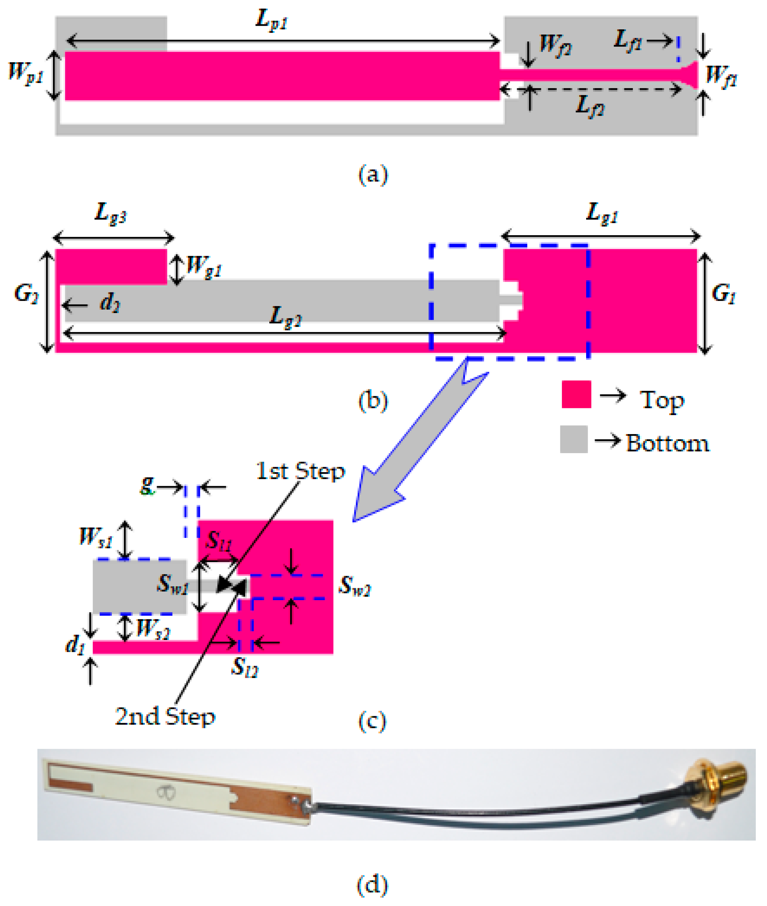
2. Wideband Antenna Design

The layout of the presented antenna, with detailed dimensions, is displayed in Figure 1. As shown in Figure 1, it is comprised of an I-shaped driven strip (radiator) and a rectangular ground strip with an open slot in the middle. The radiator, with a dimension of Wp1 × Lp1, is etched on one side of a Roger’s substrate material of thickness 0.5 mm, relative permittivity of 3.45 and a loss tangent of 0.0036, as depicted in Figure 1a. The length of the radiating patch (45 mm) is about a quarter of the wavelength at the fundamental mode and controls the excitation of the first resonance of the antenna at about 1.67 GHz. The feeding of the proposed antenna is accomplished by a 50Ω microstrip line, which is added to the lower end of driven strip. The width and length of the feedline are, respectively, Wf2 and Lf2. The end of the feedline is tapered and has a size Wf1 × Lf1. For RF signal input, a 50Ω SMA connector is connected to the strip line.
As presented in Figure 1b, the ground strip with length Lg1 + Lg2 + d2 is etched on the other side of the substrate and is shorted at the feed point. The widths of the two ends of the ground strip are G1 and G2. At the middle of the ground strip, there is an open slot of size (G2 − Wg1) × Lg2. To attain better coupling between the driven strip and ground strip, the lower portion of the open slot of the ground strip is steeped, as shown in Figure 1c. The dimensions of the first step and second step are, respectively, S11 × Sw1 and S12 × Sw2. The detail dimensions of the driven strip and the ground strip, as well as the presented antenna, are summarized in Table 1.
To understand the design consideration and working principle, the simulated S11 is depicted in Figure 2, where we can observe that the designed antenna exhibits a dual-resonant mode. As the I-shaped driven strip is used as radiator, it creates a 0.25-λ resonant mode at around 1.67 GHz, which is the fundamental mode. The resonance frequency for this mode can be calculated using the equation
f r v 4 l p 1
where v is velocity of the electromagnetic wave in the substrate. As the lower end of the open slot is steeped, the driven strip also creates a higher 0.3-λ resonant mode at around 2.08 GHz. By merging the two resonant modes, an operating band ranging from 1.585 MHz to 2.195 MHz is achieved.
To better understand the resonance modes, the surface current of the presented antenna at 1.67 and 2.08 GHz is displayed in Figure 3. As shown in Figure 3a, at 1.67 GHz, the current is relatively strong at the driven strip which is marked red and current distributions are observed in the longer path along the microstrip line to the I-shaped driven strip. That is to say, the driven strip creates the fundamental mode at around 1.67 GHz, which corresponds to the quarter wavelength of the resonant mode. For 2.08 GHz, as shown in Figure 3b, the surface current distributions are densely concentrated on the driven strip, as well as the steeped portion of the open slot. This surface current distribution indicates that the resonance at around 2.08 GHz is also generated by the 0.3-λ mode of the driven strip. From Figure 3, it can be noted that the surface current at 1.67 and 2.08 GHz are along the same path and the resonance modes of the designed antenna are slightly altered by each other. The merging of these two resonance modes results in a wide operating band suitable for GSSP, AWS, DCS, DCP, PCS, PHS, MCDMA, UMTS and LTE band applications.
To examine the compactness, the performance of the proposed antenna in terms of bandwidth, both the electrical dimension and the bandwidth dimension ratio (BDR) are compared with antennae that were recently reported for the WWAN/LTE applications; these comparisons are presented in Table 2. In the comparison, all the antennae are assumed to be planar and the differences in their dielectric constants are taken to be small. Although the proposed antenna achieved a small operating band in comparison to the others, a good BDR of 3439 with a small electrical size of 0.35λ0 × 0.027λ0 is achieved. Moreover, as the proposed design does not require a larger ground plane, it can directly be printed onto a mobile phone without any extra space being necessary. Hence, the designed antenna can offer a low profile while maintaining a much smaller volumetric size.

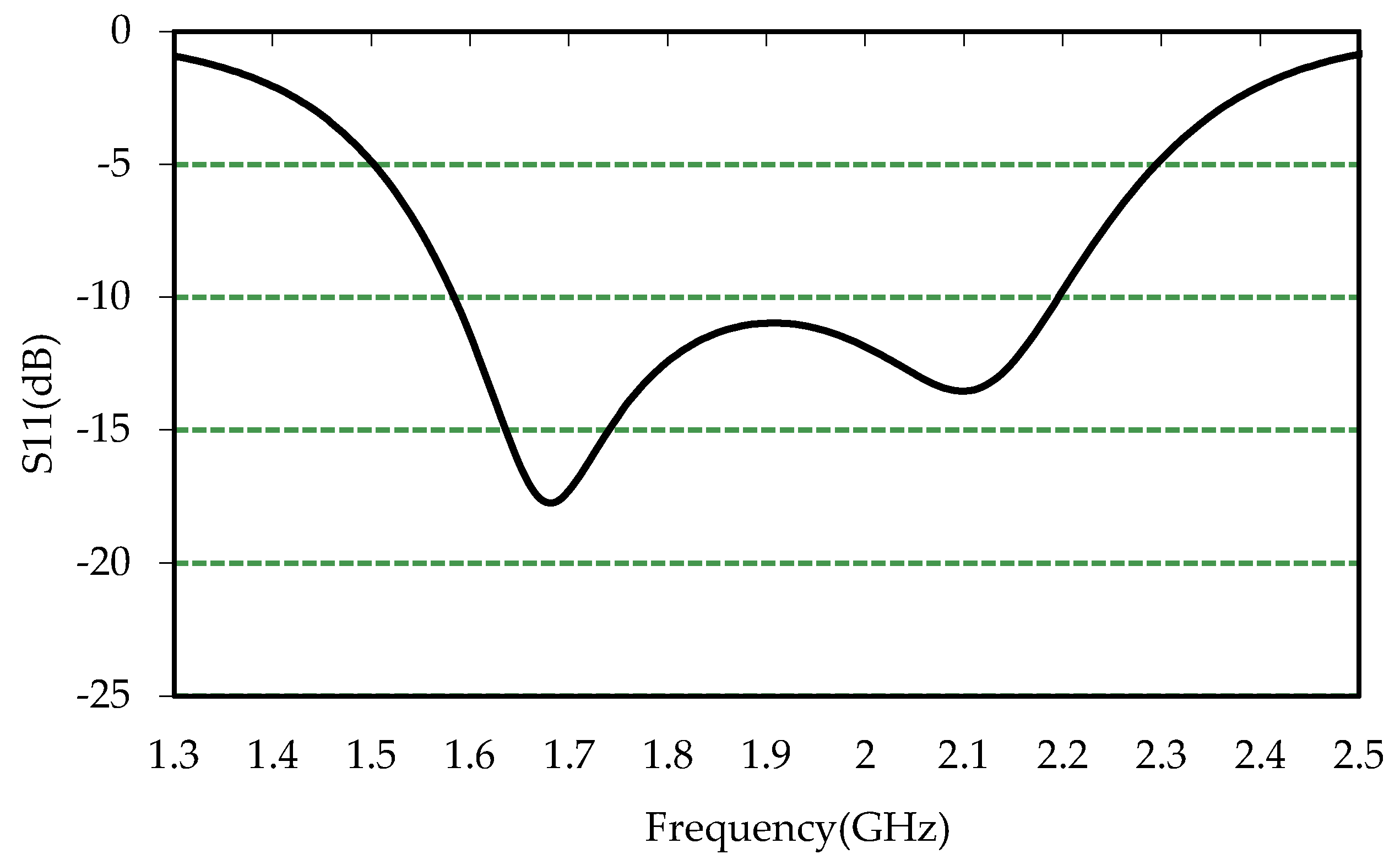
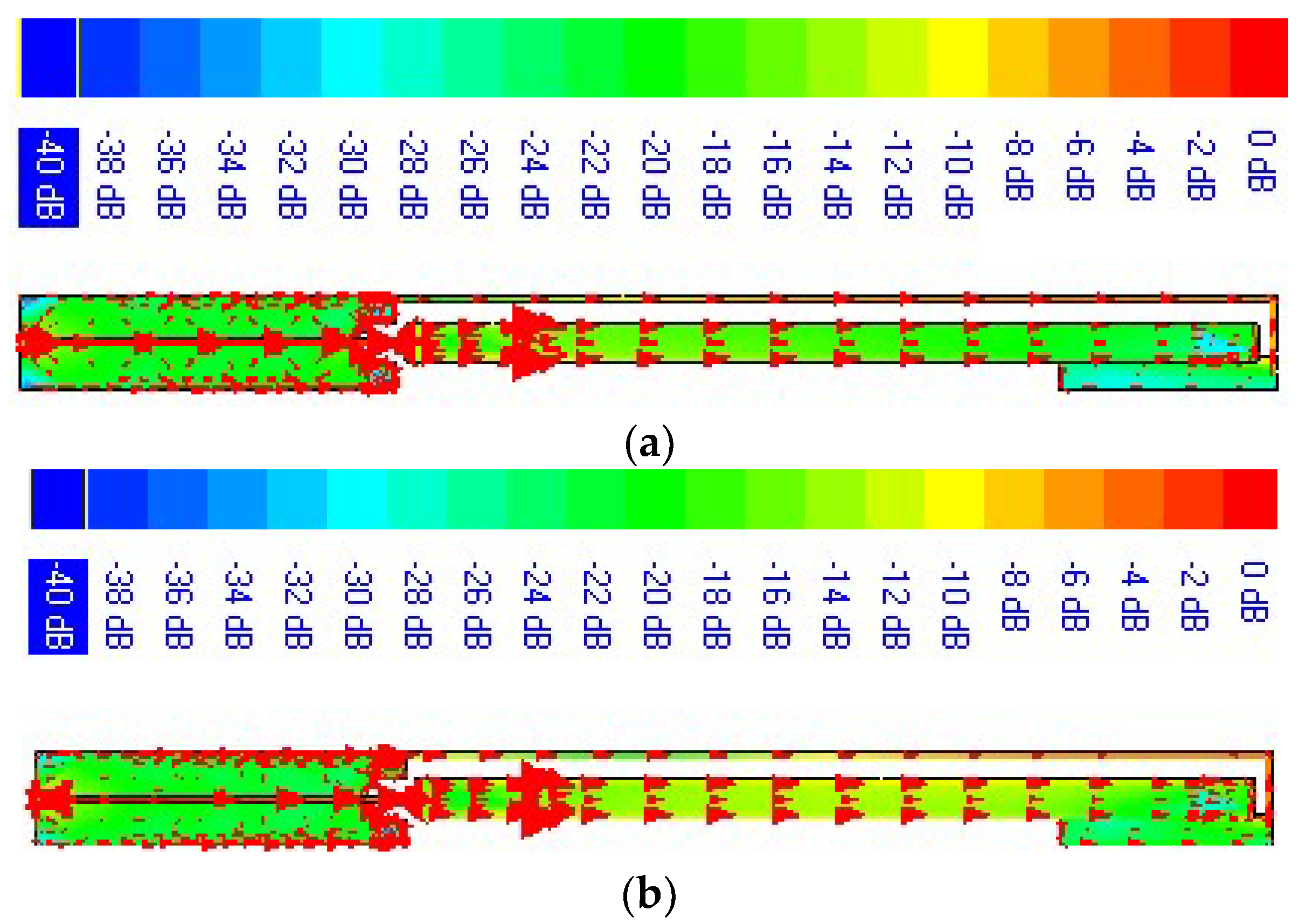
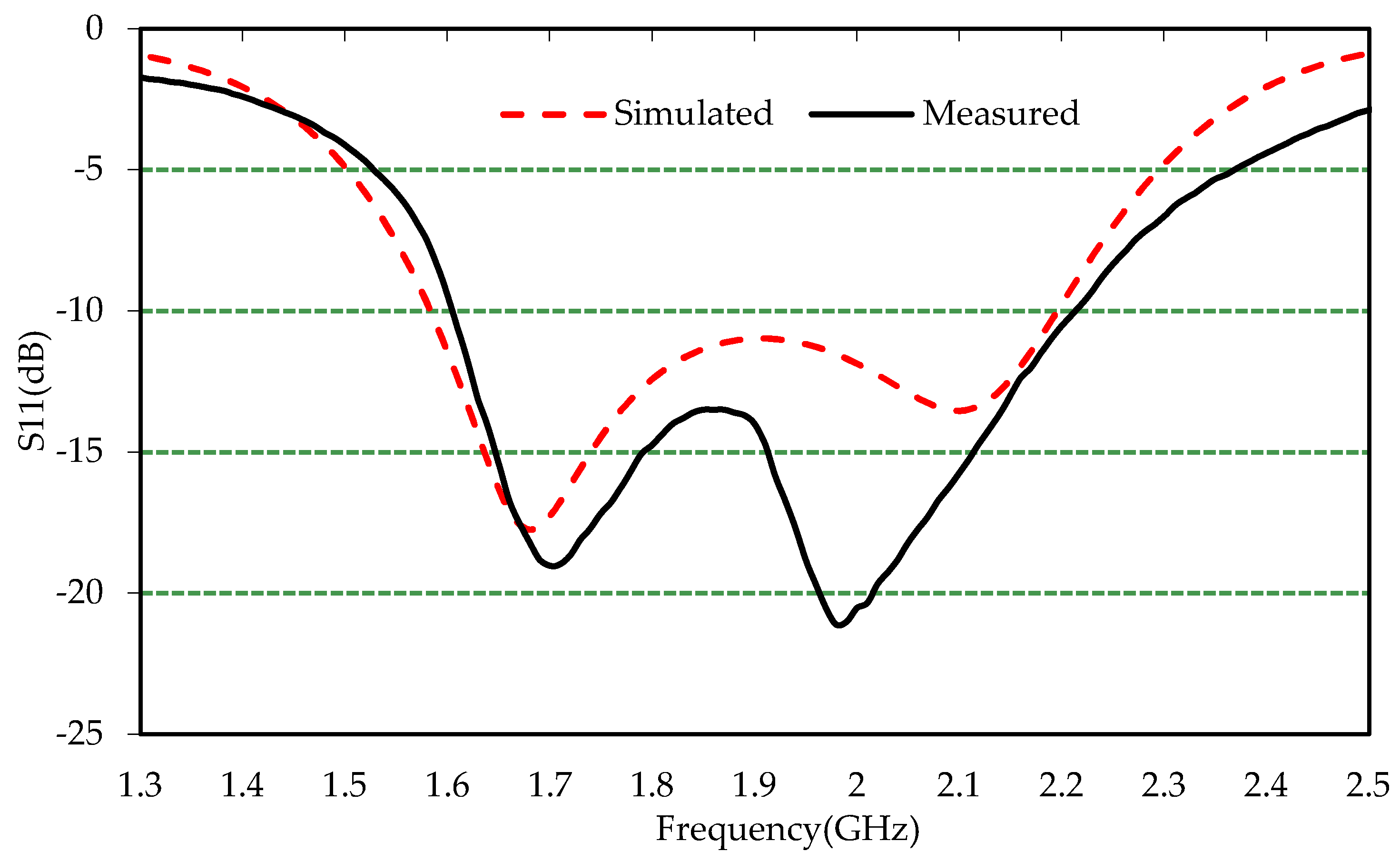
3. Results and Discussion

The presented antenna is analyzed and optimized using IE3D software. All the parameters of designed antenna, such as the size of the driven strip, ground strip and feedline are optimized to achieve the required operating bands. To examine the behavior of the designed antenna, a pair of antennae are prototyped, as displayed in Figure 1d. Figure 4 demonstrates the simulated and measured S11 of the fabricated prototype, which is measured with the help of a network analyzer (Agilent N5227A). It can be revealed from the plot that the measured results almost coincide with the simulated ones. The disagreement between the results is mainly caused by a prototyping error and a measurement error. The measured results demonstrate that two resonant modes are excited, and these two nearby modes are merged to form a wider operating band. The measured −10dB bandwidth ranges from 1610 MHz to more than 2210 MHz and almost satisfies the entire requirement of a mobile phone, such as Globalstar satellite phones (uplink), advanced wireless systems, DCS, digital cordless phones, DCS-1900/PCS/PHS, WCDMA/IMT-2000, UMTS, LTE (Bands 1–4, 9–10, 15–16, 23–25) bands.
The radiation characteristics of the proposed antenna are measured using Satimo’s StarLab near-field antenna measurement system. The measured gain and efficiency of the prototype is presented in Figure 5, where it is revealed that, in the achieved operating band, the gain is about 0.76 to 2.45 dBi and the efficiency varies from 34% to 48%, which fulfils the requisite characteristics of many practical applications. The measured 2D radiation characteristic of the prototype is displayed in Figure 6. It is observed from the figure that the pattern in the E-plane is almost omnidirectional. In the H-plane, the patterns are almost dipole-like with the introduction of nulls, especially at higher frequencies. Despite the nulls in the H-plane, it can be revealed from the plot that the presented design exhibits the characteristics of stable radiation throughout the operating band, which is a prime requisite for mobile communication applications. As the designed antenna exhibits symmetric radiation characteristics over the entire operating band, it can be treated as a wideband antenna that has the capability to transfer data at a higher rate. Figure 7 displays the measured three-dimensional radiation patterns at 1.70 GHz, which show dipole-like omnidirectional radiation.

4. Conclusions

In this paper, a low-profile wideband antenna covering frequencies ranging from 1610 MHz to 2210 MHz is reported. The antenna is made up of an I-shaped driven strip and a ground strip with an open slot in the middle and a steeped lower portion and is able to exhibit dual-resonant modes. The designed antenna occupies a small area of 5 × 66.1 mm2 and requires no system ground plane. The prototyped antenna exhibits an impedance bandwidth of 600 MHz (31.42%), which can address a number of applications, such as GSS phones (uplink), AWS, DCS, DCP, DCS-1900/PCS/PHS, WCDMA/IMT-2000, UMTS and LTE bands. The designed antenna has a simple footprint and demonstrates satisfactory performances in terms of bandwidth, gain, efficiency and radiation characteristics, which indicate that it is a promising candidate to be used in WWAN/LTE applications.

Author Contributions

R.A. and M.M.A. made substantial contributions to conception, design, and analysis, while R.A. provided the necessary instructions for experimental purposes. A.A. and M.T.I. participated in funding, supervising and revising the manuscript critically for important intellectual contents. All authors have read and agreed to the published version of the manuscript.

Funding

This project was funded by the Deanship of Scientific Research (DSR), King Abdulaziz University, Jeddah under grant number DF-559-135-1441. The authors, therefore, gratefully acknowledge DSR technical and financial support.

Acknowledgments

The authors would like to thank the King Abdulaziz University, Jeddah to sponsor the research work under the Deanship of Scientific Research (DSR) grant number DF-559-135-1441.

Conflicts of Interest

The authors declare no conflict of interest.

References

  1. Ghosh, A.; Ratasuk, R.; Mondal, B.; Mangalvedhe, N.; Thomas, T. LTE-Advanced: next-generation wireless broadband technology. IEEE Wirel. Commun. 2010, 17, 10–22. [Google Scholar] [CrossRef]
  2. Hsu, C.-K.; Chung, S.-J. Compact multiband antenna for handsets with a conducting edge. IEEE Trans. Antennas Propagat. 2015, 63, 5102–5107. [Google Scholar] [CrossRef]
  3. Belrhiti, L.; Riouch, F.; Tribak, A.; Terhzaz, J.; Sanchez, A.M. A low-profile planar monopole internal antenna for GSM/DCS/PCS/IMT/UMTS/WLAN/ ISM/LTE operation in the mobile phones. Int. J. Microw. Wirel. Technol. 2019, 11, 53–66. [Google Scholar] [CrossRef]
  4. Ban, Y.-L.; Qiang, Y.-F.; Chen, Z.; Kang, K.; Guo, J.-H. A dual-loop antenna design for hepta-band WWAN/LTE metal-rimmed smartphone applications. IEEE Trans. Antennas Propagat. 2015, 63, 48–58. [Google Scholar] [CrossRef]
  5. Belrhiti, L.; Riouch, F.; Tribak, A.; Terhzaz, J.; Sanchez, A.M. Internal compact printed loop antenna for WWAN/WLAN/ISM/LTE smartphone applications. Int. J. Microw. Wirel. Technol. 2017, 9, 1961–1973. [Google Scholar] [CrossRef]
  6. Lee, B.; Harackiewicz, F.J.; Wi, H. Closely mounted mobile handset MIMO antenna for LTE 13 band application. IEEE Antennas Wirel. Propagat Lett. 2014, 13, 411–414. [Google Scholar]
  7. Zhou, D.; Abd-Alhameed, R.A.; See, C.H.; Alhaddad, A.G.; Excell, P.S. Compact wideband balanced antenna for mobile handsets. IET Microw. Antenna Propagat. 2010, 4, 600–608. [Google Scholar] [CrossRef]
  8. Tang, R.; Du, Z. Wideband monopole without lumped elements for octa-band narrow-frame LTE smartphone. IEEE Antennas Wirel. Propagat Lett. 2016, 16, 720–723. [Google Scholar] [CrossRef]
  9. Shen, D.-L.; Zhang, L.; Weng, Z.-B.; Chen, C.-H.; Jiao, Y.-C. Compact monopole with a band-stop matching circuit for LTE/WWAN smartphone. Microw. Opt. Technol. Lett. 2018, 60, 2357–2363. [Google Scholar]
  10. Amani, N.; Jafargholi, A. Strip-like internal antenna for GPS/Glonass/LTE/GSM/WLAN and near-field applications. Int. J. Electron. Lett. 2019, 7, 77–84. [Google Scholar] [CrossRef]
  11. Amani, N.; Jafargholi, A. Internal uni-planar antenna for LTE/WWAN/GPS/GLONASS applications in Tablet/Laptop computers. IEEE Antennas Wirel. Propagat. Lett. 2015, 14, 1654–1657. [Google Scholar] [CrossRef]
  12. Wong, K.L.; Lee, L.C. Multiband printed monopole slot antenna for WWAN operation in the laptop computer. IEEE Trans. Antennas Propagat. 2009, 57, 324–330. [Google Scholar] [CrossRef]
  13. Raviteja, G.V.; Lakshmi, V.R. Gain and bandwidth investigations of a novel PIFA antenna employing partial ground at 2.3 GHz for WiMAX/WiFi/WLAN applications. Microw. Opt. Technol. Lett. 2019, 61, 1841–1844. [Google Scholar] [CrossRef]
  14. Yang, Y.; Zhao, Z.; Yang, W.; Nie, Z.; Liu, Q.-H. Compact multi-mode monopole antenna for metal-rimmed mobile phones. IEEE Trans. Antennas Propagat. 2017, 65, 2297–2304. [Google Scholar] [CrossRef]
  15. Ahmad, A.; Tahir, F.A.; Cheema, H.A. A compact uniplanar antenna for nine-band LTE/WWAN operation in tablet computers. Int. J. RF Microw. Comput-aided. 2016, 26, 496–502. [Google Scholar] [CrossRef]
  16. Deng, C.; Li, Y.; Zhang, Z.; Feng, Z. Planar printed multi-resonant antenna for octa-band WWAN/LTE mobile handset. IEEE Antennas Wirel. Propagat. Lett. 2015, 14, 1734–1737. [Google Scholar] [CrossRef]
  17. Wong, K.L.; Liao, Z.G. Passive reconfigurable triple wideband antenna for LTE tablet computer. IEEE Trans. Antennas Propagat. 2015, 63, 901–908. [Google Scholar] [CrossRef]
  18. Dong, J.; Yu, X.; Deng, L. A decoupled multiband dual-antenna system for WWAN/LTE smartphone applications. IEEE Antennas Wirel. Propagat. Lett. 2017, 16, 1528–1532. [Google Scholar] [CrossRef]
  19. Chen, K.-R.; Sim, C.-Y.-D.; Row, J.-S. A compact monopole antenna for super wideband applications. IEEE Antennas Wirel. Propagat. Lett. 2011, 10, 488–491. [Google Scholar] [CrossRef]
  20. Dorostkar, M.A.; Islam, M.T.; Azim, R. Design of a novel super wide band circular-hexagonal fractal antenna. Prog. Electromagn Res. 2013, 139, 229–245. [Google Scholar] [CrossRef] [Green Version]
  21. Dong, Y.; Hong, W.; Liu, L.; Zhang, Y.; Kuai, Z. Performance analysis of a printed super-wideband antenna. Microw. Opt. Technol. Lett. 2009, 51, 949–956. [Google Scholar] [CrossRef]
  22. Bybi, P.C.; Augustin, G.; Jitha, B.; Aanandan, C.K.; Vasudevan, K.; Mohanan, P. A quasi-omnidirectional antenna for modern wireless communication gadgets. IEEE Antennas Wirel. Propagat. Lett. 2008, 7, 505–508. [Google Scholar] [CrossRef] [Green Version]
Figure 1. Layout of the proposed wideband antenna (a) front view, (b) back view, (c) steeped ground strip, and (d) prototype.
Electronics 09 00393 g001
Figure 2. Simulated S11 of the proposed antenna.
Electronics 09 00393 g002
Figure 3. Current distributions at (a) 1.67 and (b) 2.08 GHz.
Electronics 09 00393 g003
Figure 4. Simulated and measured S11.
Electronics 09 00393 g004
Figure 5. Measured gain and efficiency of the proposed antenna.
Electronics 09 00393 g005
Figure 6. Measured radiation patterns at different frequencies (a) E-plane, and (b) H-plane.
Electronics 09 00393 g006
Figure 7. Measured 3D radiation pattern at 1.70 GHz.
Electronics 09 00393 g007
Table 1. Design parameters of the proposed antenna.
ParametersValue(mm)ParametersValue(mm)
Wf11.0Lg311.5
Lf12.0Wg11.7
Wf20.4d10.4
Lf218.5d20.4
Wp12.0Ws11.5
Lp145Ws21.1
G15.0Sw12.0
G25.0Sl11.5
Lg120Sw21.0
Lg246.1Sl20.5
Table 2. Comparison of the proposed antenna with some recently reported antennae.
Antenna−10dB BW (%)flow (GHz)Electrical DimensionSize (λ02)BDRfcenter (GHz)Maximum
Gain(dBi)
This work32.51.600.35 × 0.0270.0094534391.912.45
[19]1721.440.37 × 0.170.0629273510.127
[20]1812.180.23 × 0.330.0759246211.097
[21]1850.640.32 × 0.340.108817308.3210
[7]371.710.274 × 0.0860.023615792.355.4
[22]761.540.33 × 0.160.052814392.503.5
[6]5.30.7460.149 × 0.0370.00559610.767Not provided

