EARL—Embodied Agent-Based Robot Control Systems Modelling Language

 ,
,  , ,
, ,  , and
, and 
Abstract
1. Introduction
1.1. MDSD in Robotics
- Are based on formal models—rules and constraints defined by MDSD language are represented in the form of a formal model.
- Enable direct transformation of the specification into implementation—specific entities defined in the MDSD tools map to specific entities of the framework used for the creation of the robot software, e.g., components, communication channels and data types.
- Are compatible with open source frameworks—the specification can be easily transformed into executable code created by using open source frameworks.
- Are supplemented with controller code creation software—the MDSD tool provides or can cooperate with mechanisms that enable the transformation of specifications into the robot controller code.
1.2. SysML
1.3. Embodied Agent
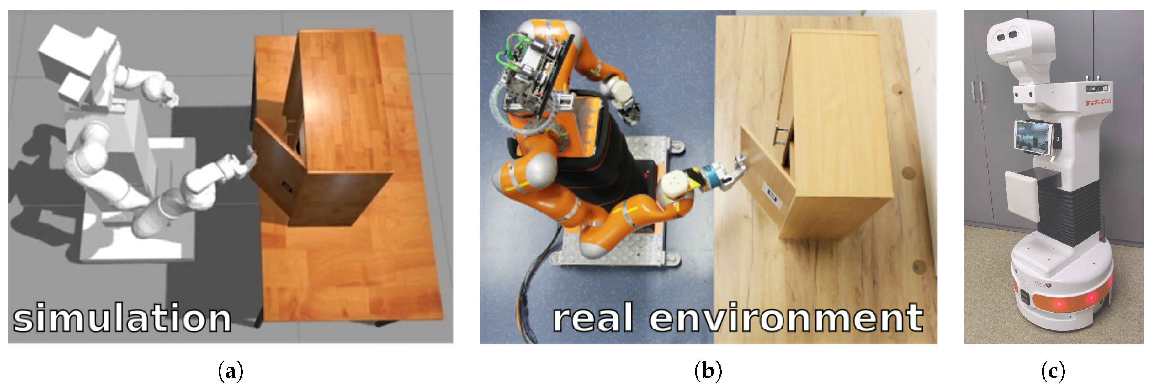
- Industrial robots, e.g., modified IRb-6 manipulator [34], whose control software was an inspiration for the example included in this article.
- Service robots, e.g., Velma robot [37].
- Mobile robots, e.g., Lynx [41], with selectable modes of locomotion, either horizontal or vertical.
- Skid steering platform Rex [42].
- General model of the wheeled robot [43].
- Social robots [44].
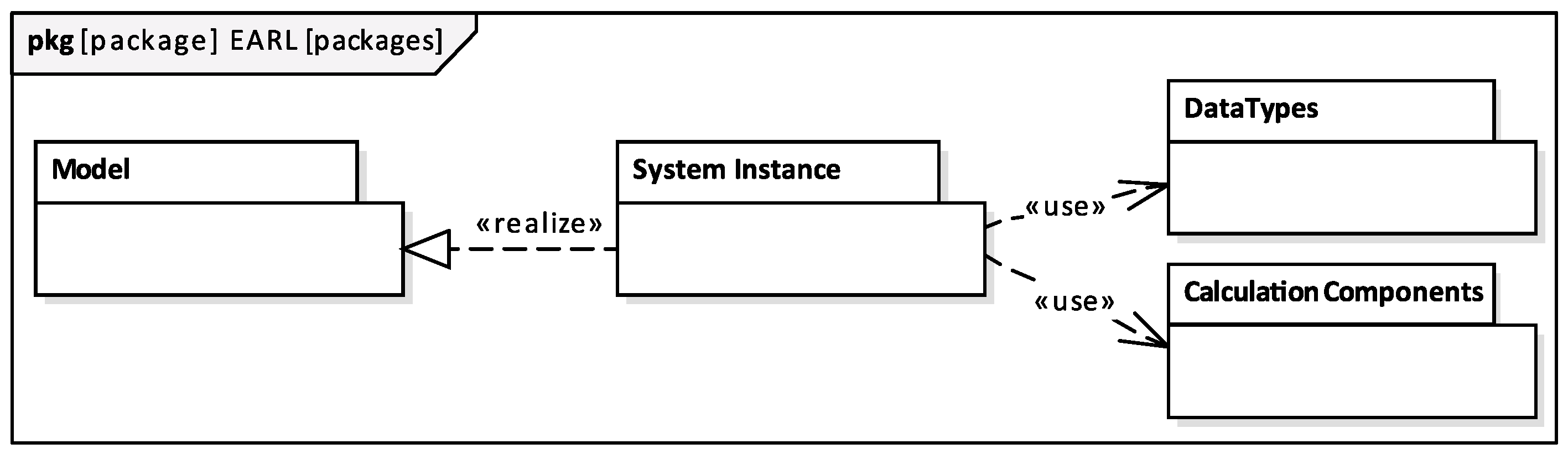
1.4. EARL
- How to organize a specification into SysML packages?
- For what purposes should the graphical tools be used and where the mathematical notation should be applied directly?
- How to map the specification into component systems?
- How to describe systems with a time-varying structure?
2. Model Formulation
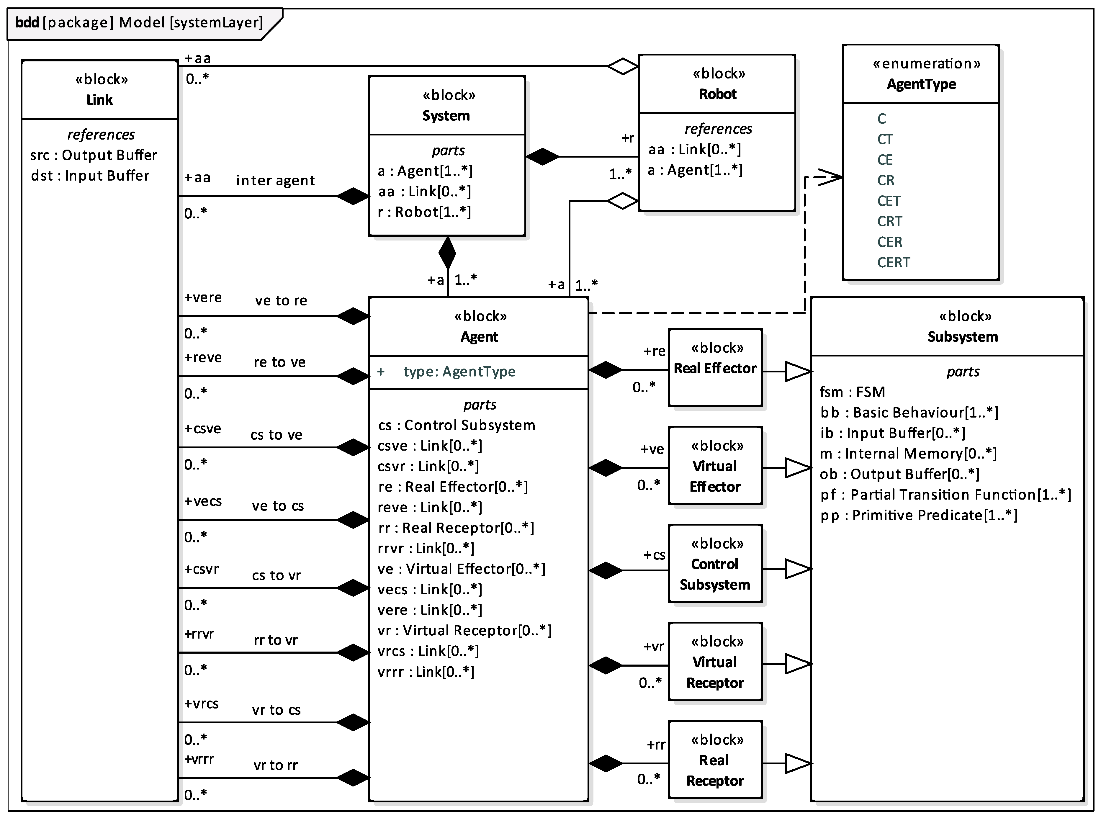
2.1. System and Its Parts
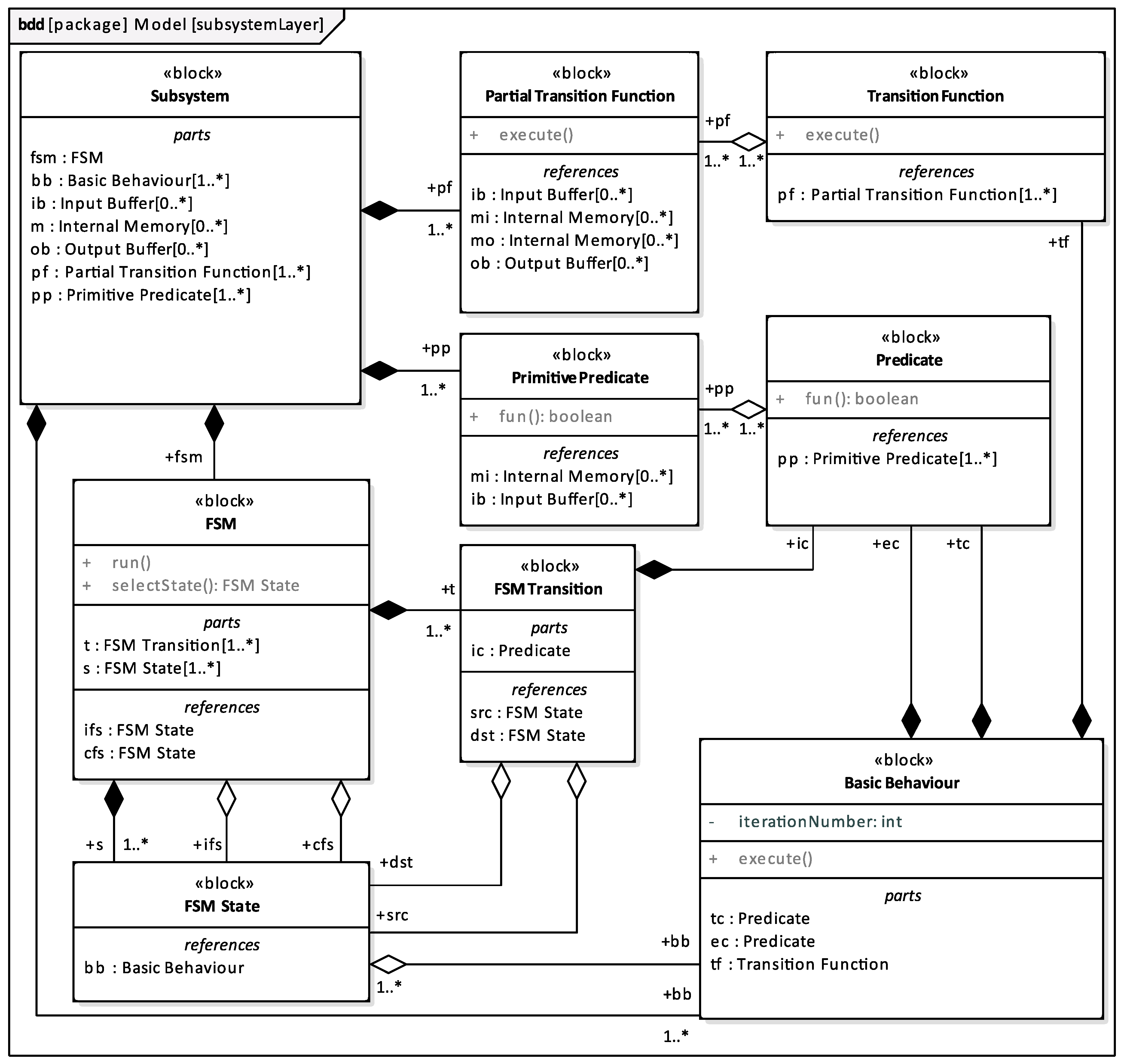
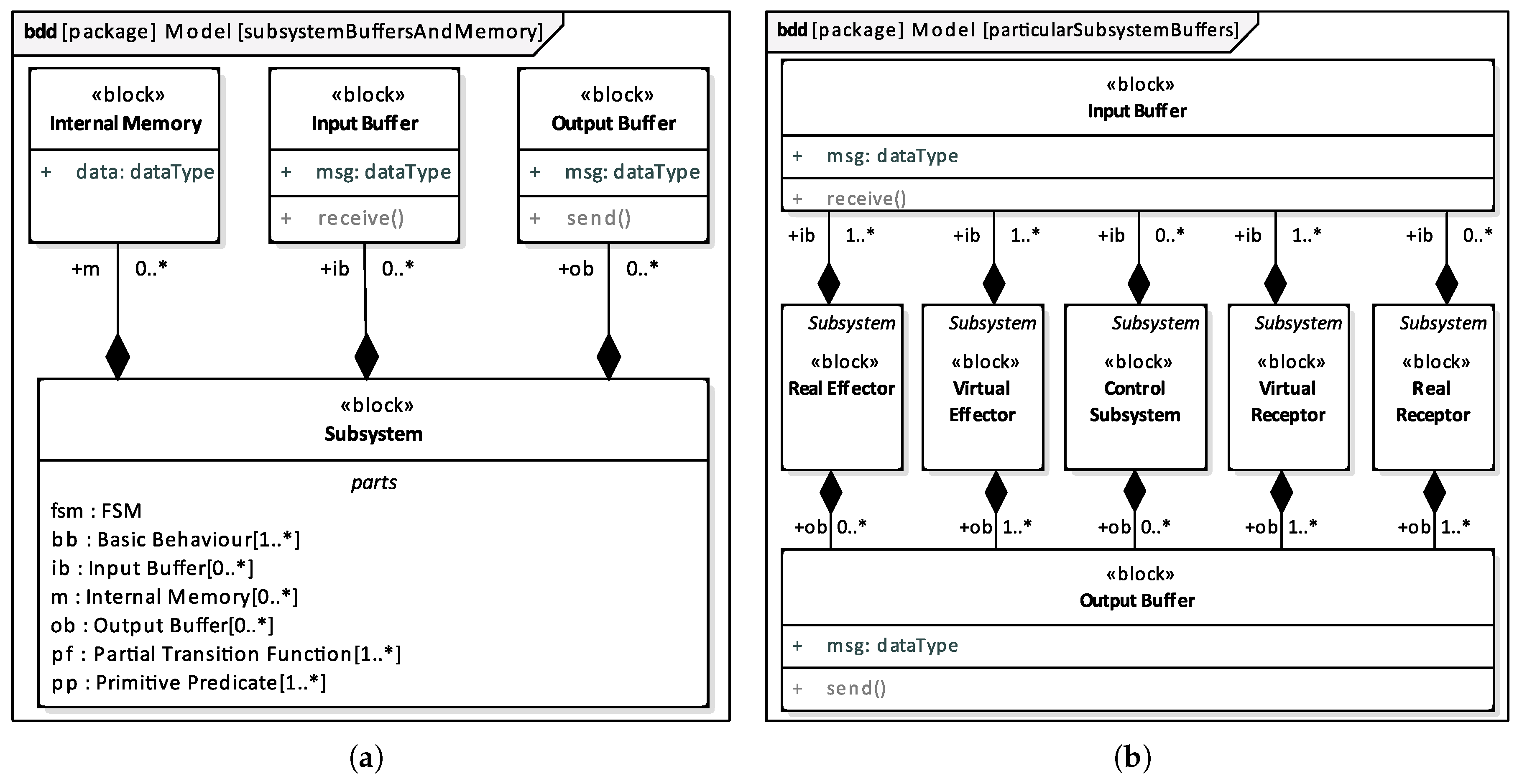
2.2. Subsystem and Its Parts
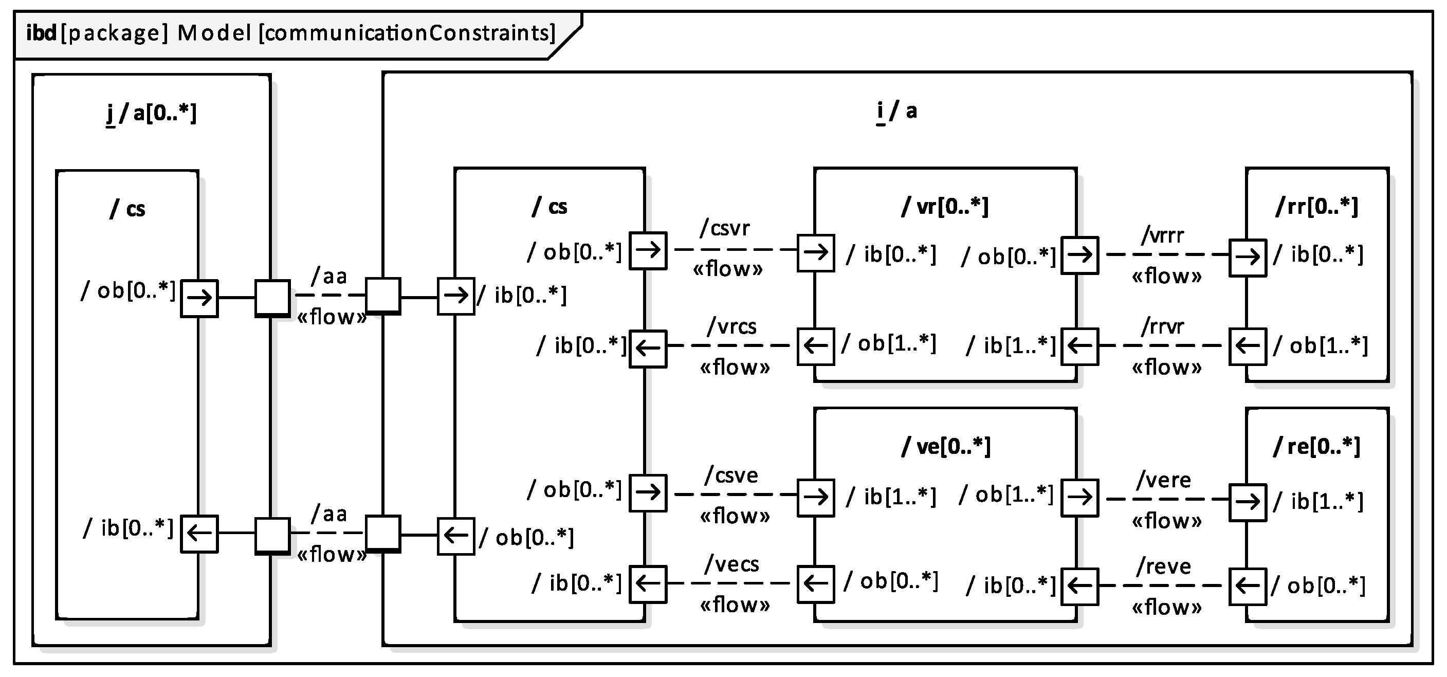
2.3. Embodied Agent Communication
2.4. Types of Agents
- C—overall control of the agent,
- E—exerting influence over the environment by using effectors,
- R—gathering the information from the environment by using receptors, and
- T—inter-agent communication (transmission).
2.5. Specification of a Particular Robot Control System
- model and system instance constraints that can not be practically formulated in diagrams,
- fun operations of Predicates and Primitive Predicates, and
- some calculations performed inside actions of Activity Diagrams of Partial Transition Functions, e.g., control laws.
3. Example of a System Specified Using EARL
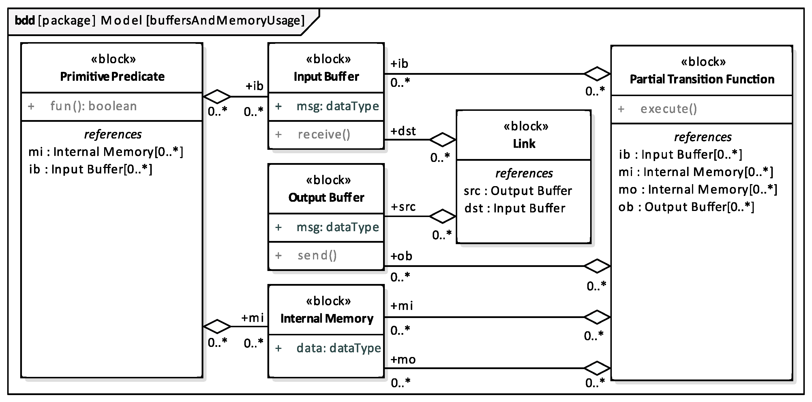
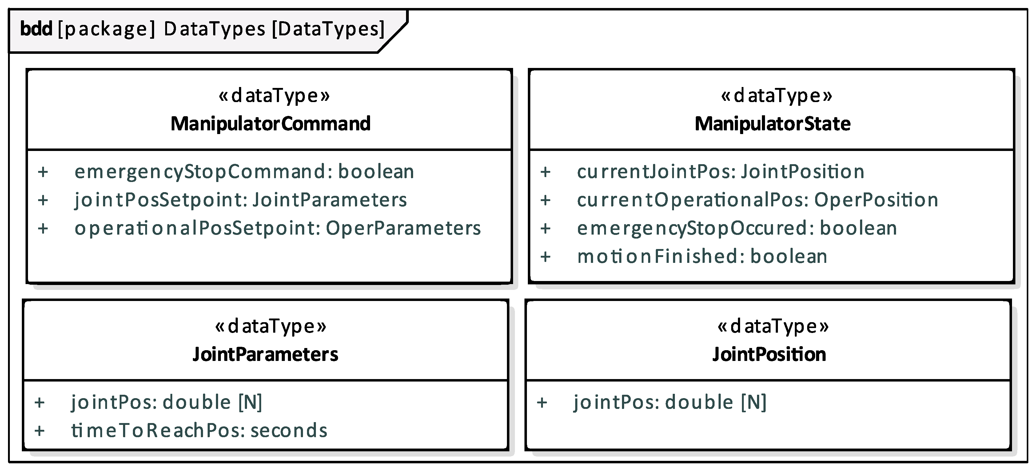
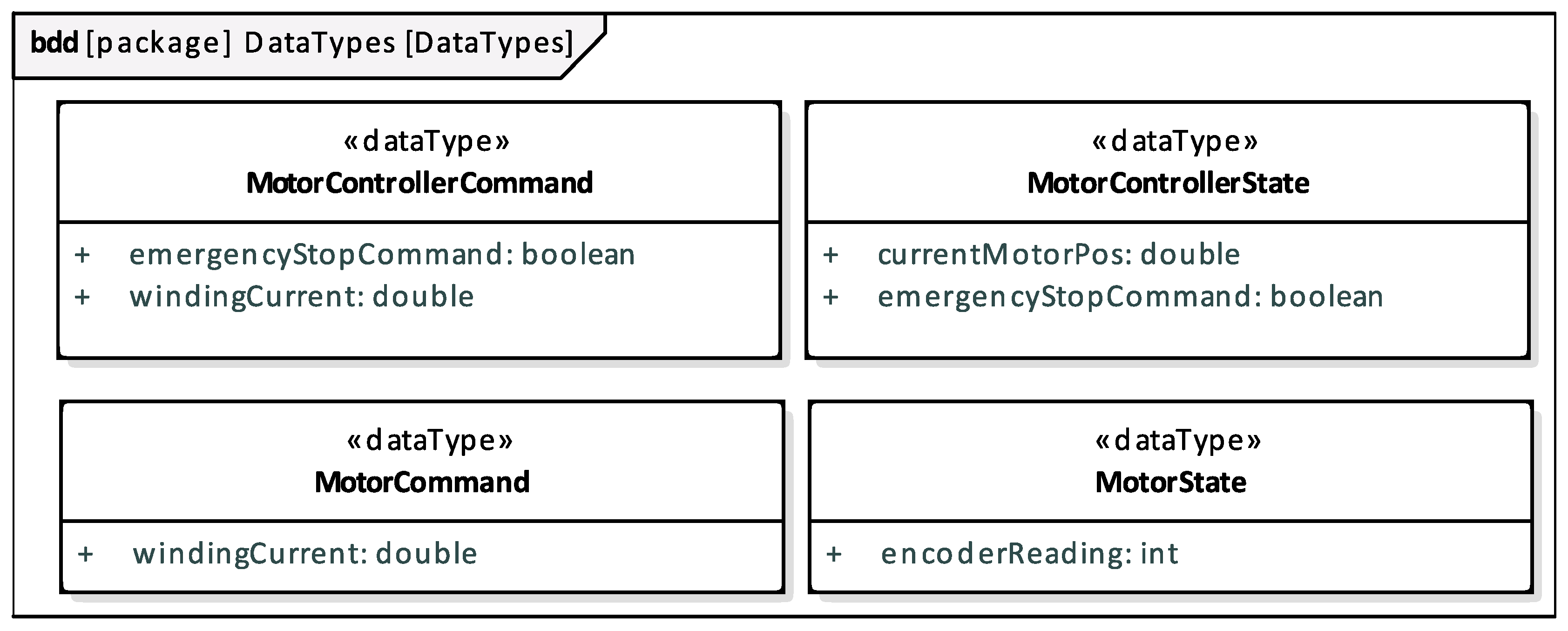
- Structure of the whole System with Buffers, Internal Memories, inter Agent communication Links, and dataTypes used by them.
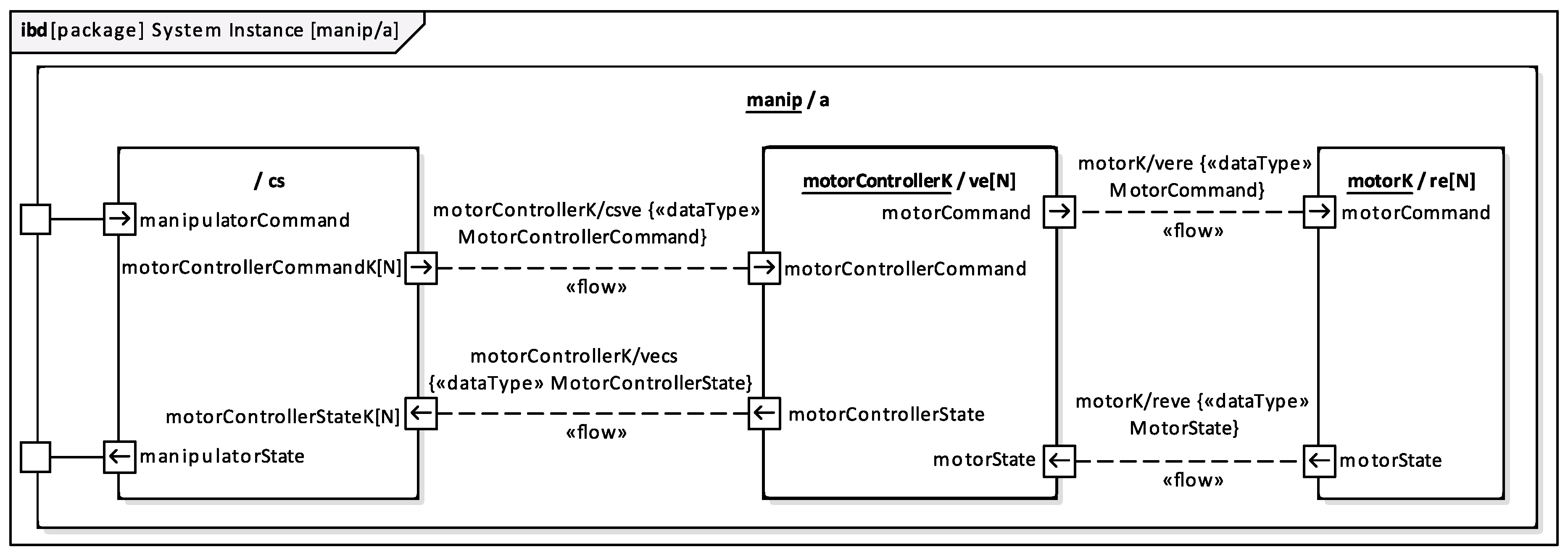
- Structure of the particular Agent with Buffers, Internal Memories, inter Subsystem communication Links, and dataTypes used by them.
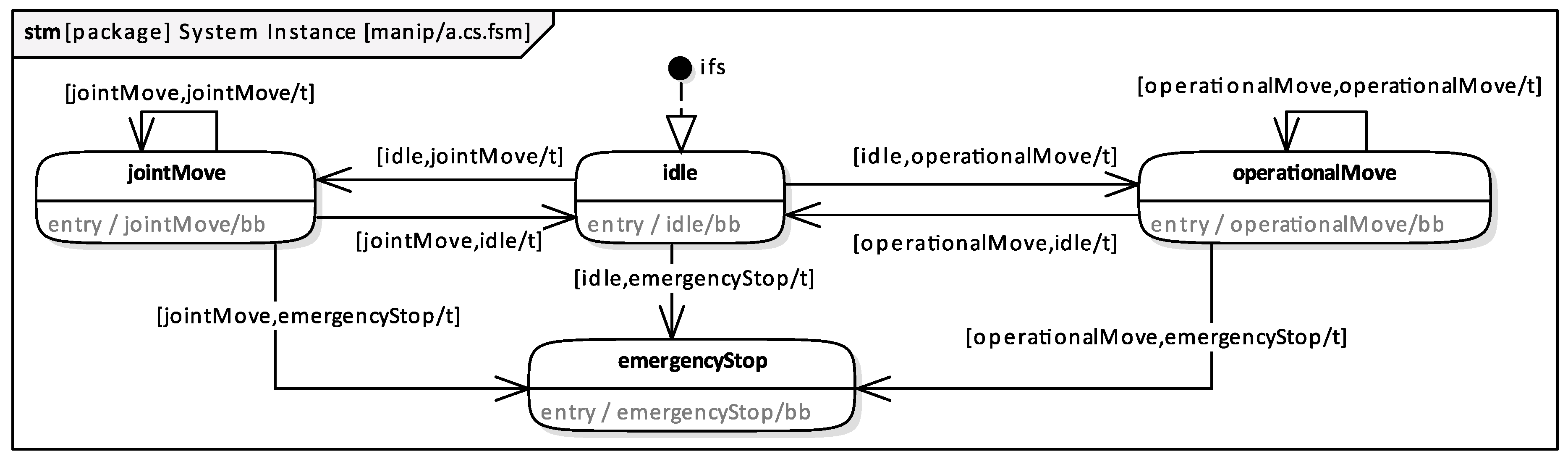
- Specification of a particular Subsystem, its structure and behaviour, i.e., Buffers, Internal Memories, dataTypes, FSM, Basic Behaviours and their Terminal Conditions and Error Conditions; Primitive Predicates, FSM Transitions and their Initial Conditions; method of both composition and execution of Partial Transition Functions and control law utilised in the activity diagram of Partial Transition Function.
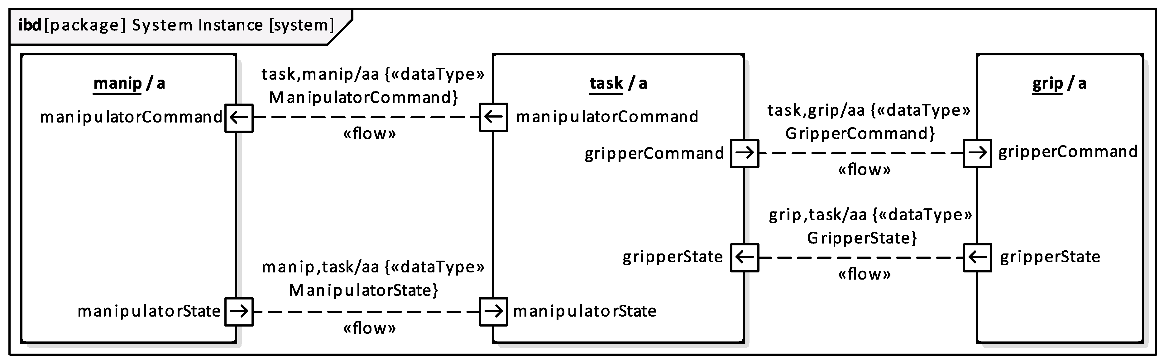
3.1. Structure of the System Composed of Agents
3.2. Manipulator Agent
- —calculates manipulator joint positions and end-effector operational space pose.
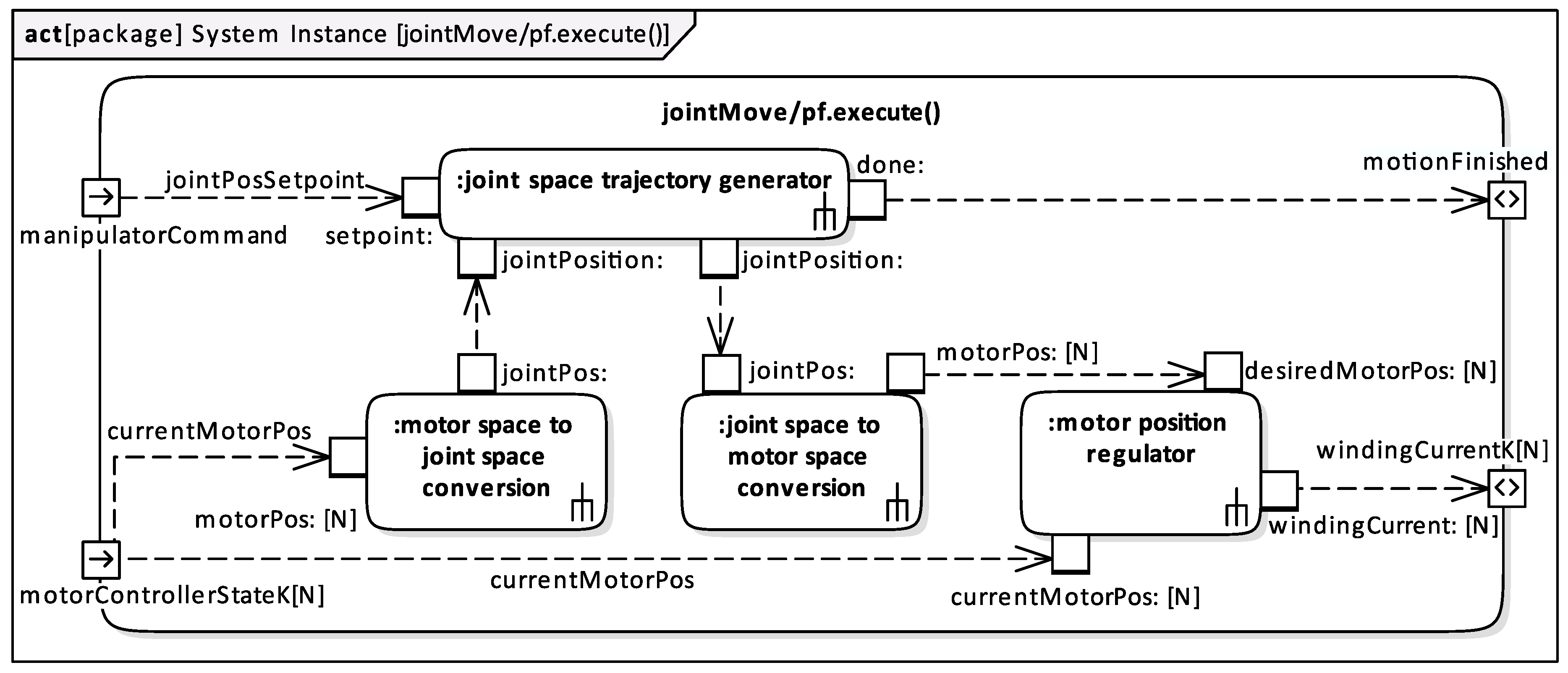
- /—generates the joint/operational space trajectory and calculates the winding current needed to realize the motion (Figure 13).
- —calculates the winding current needed to keep the manipulator in a stationary position.
- —copies the information about the occurrence of an emergency stop to Output Buffers that are linked to the associated Subsystem Input Buffers.
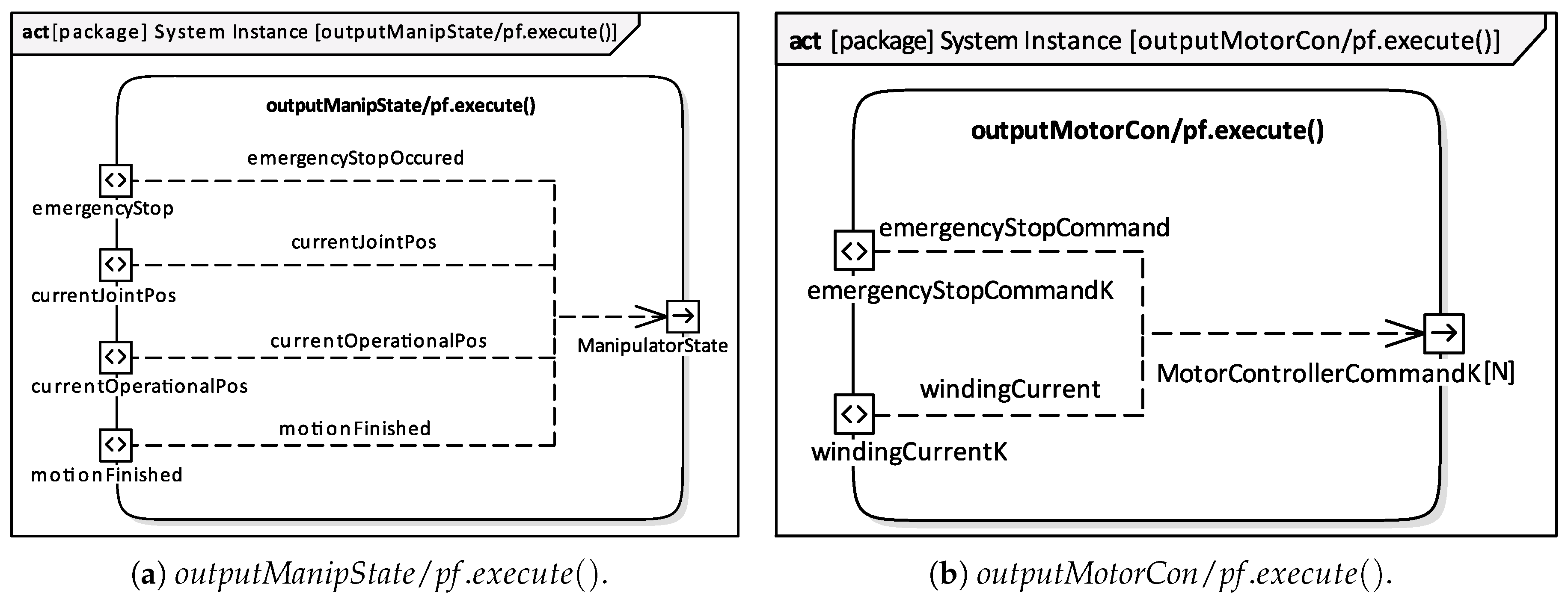
- —composes (Figure 14a).
- —composes (Figure 14b).
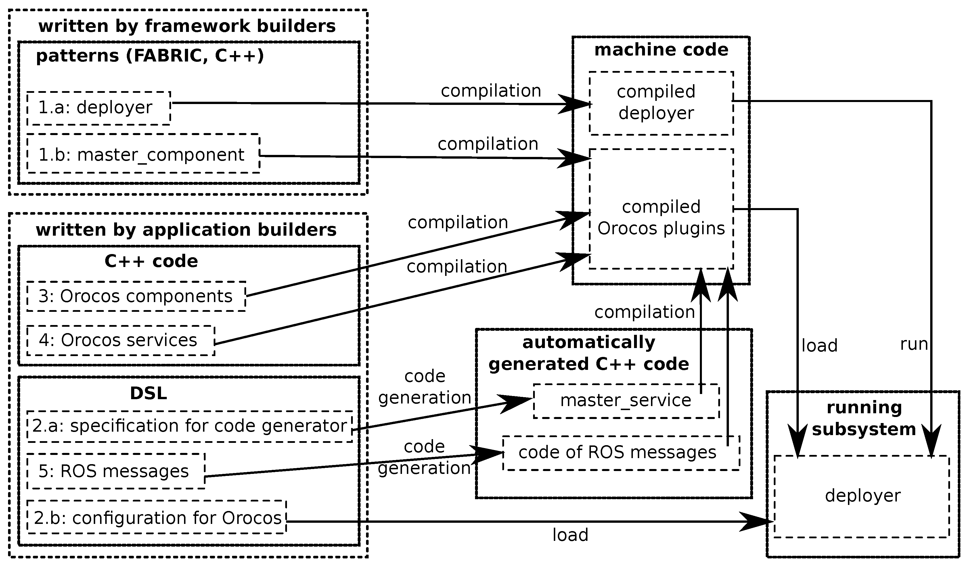
4. FABRIC Framework
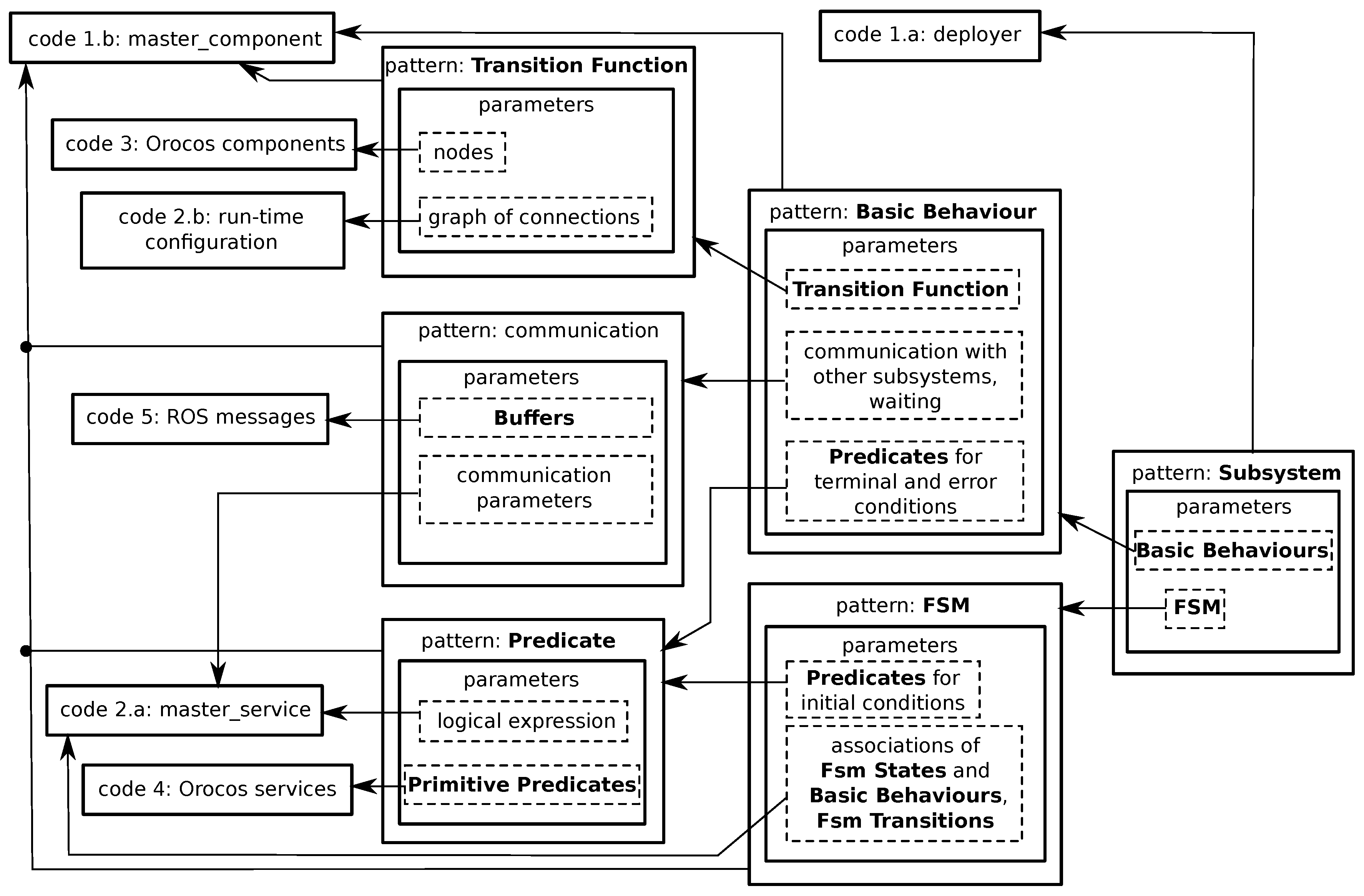
- FABRIC—framework code, common to all Subsystems; it was manually written by the framework builders; it invokes Subsystem specific parts of code loaded at run-time; it is composed of the following items.
- a)
- deployer—code that loads Orocos framework together with its components and configures them.
- b)
- master_component—a specialised Orocos component that manages the activities of the subsystem.
- Subsystem specification complying with MDSD, created by application builders, and delivered as two separate XML files:
- a)
- The first complies with the EARL system model containing the definitions of FSM, terminal and error conditions of Basic Behaviours, initial conditions of FSM Transitions, dataTypes and and operations employed by the Buffers,.
- b)
- The second is used for run-time configuration; it contains the description of Orocos components that compose the Transition Functions, and the parameters of those components.
- Orocos components that form Partial Transition Functions, written by component builders; the set of components that are to be used is selected by application builders.
- Source code of the Primitive Predicates produced by application builders; it is delivered in the form of Orocos services.
- ROS message definitions specifying dataTypes of the variables composing the Buffers; this code is written by application builders.
5. Discussion
- Composability—in the phase of system integration, all the main properties of components should remain unchanged. The problem may concern, e.g., duplication of component names. EARL and other discussed MDSD languages do not meet this requirement.
- Compositionality—ensures correct operation of the system composed of components. System performance can be predicted for each reused component composition. In the case of EARL, this refers to, e.g., the composition of Partial Transition Function out of Calculation Components and creation of an Agent out of Subsystems. In both cases, the Calculation Components can be reused to create different structures, but EARL does not provide mechanisms verifying the correctness of the composition. EARL describes constraints imposed on communication between Subsystems and requirements for compatibility of communication Link dataTypes (Section 2.3). However, checking the fulfillment of these requirements is the responsibility of the system designer. Other discussed MDSD languages do not meet the compositionality requirement either.
- Static Variability—set of constraints imposed on the communication between specific parts of the system. All the discussed approaches have this feature. EARL also fulfills this requirement by defining restrictions imposed on the communication between Subsystems (Section 2.3).
- Dynamic Variability—during system operation, the structure of connections can vary. Out of the MDSD languages considered here SmartSoft and EARL have this capability. EARL assumes that the connection structure between Agents may vary during System operation.
- Component Abstraction—refers to component-based systems. EARL and all other MDSD languages discussed here meet this requirement. In EARL, a Calculation Component as well as an Agent or Subsystem can be treated as a component.
- Technology Neutrality—system specification should be independent of the system implementation technology. EARL as well as all the other MDSD languages discussed here have this feature. EARL is based on the concept of Embodied Agent, which abstracts away the implementation details. EARL itself is adapted to component systems and can be used, for the specification of ROS and Orocos based systems.
- Knowledge Model—MDSD is based on domain knowledge represented, for example, in the form of an ontology [59]. RobotML is based on an ontology that defines various concepts, entities and relationships between them, pertaining to the domain of robotics. EARL is based on the concept of an Embodied Agent, which can be treated as an ontology defining such robotics concepts as effector, receptor, control subsystem, communication buffers, internal memory, FSM, behaviour and transition function. Those concepts enable the composition of a robot system architecture taking into account the separation of concerns approach to software design [60], resulting in a hierarchic layered system.
- System Level Reasoning—refers to reasoning about the execution time or the model semantics. Only SmartSoft implements some aspects of this kind of reasoning.
- Non-Functional Property Model—defines such aspects of the system operation as reliability or performance. None of the discussed MDSD languages address this aspect. EARL also does not, but it is based on SysML, which enables the definition of such requirements.
- Utilisation of well known graphical specification languages—EARL is based on the SysML standard, RobotML implements a UML profile, SmartSoft relies on the UML standard, BCM (BRICS) defines a meta-model using UML and V3CMM although does not use UML directly, it adopts and adapts it.
- Reliance on a formal model—EARL uses the formal SysML notation, V3CMM uses Object Constraint Language (OCL) to define model constraints formally. Although no information on the use of formal models to define the other MDSD languages has been found by us, it can be assumed that they are formally defined, because it is possible to generate executable code out of them. It should be emphasised, that defining the model in the form of a UML profile can be considered as a formal description as there are tools enabling the verification of the correctness of instances of such models.
- Direct transformation into implementation—BCM (BRICS) supports model to model (M2M) transformation, which enables the transformation of a model defined in component-port-component metamodel into an Orocos component composition model. RobotML uses a code generator toolchain defined in the PROTEUS project [5]. SmartSoft uses SmartMDSD Toolchain to generate component hulls. Empty functions of the generated components are subsequently filled in with source-code by the user [61]. V3CMM transforms models defined using UML into skeletons of controllers expressed in the Ada language. EARL uses FABRIC [16] framework to transform the specification into code utilising the ROS and Orocos frameworks. The transformation of a specification into implementation is simple, because EARL was created taking into account the component nature of robotic frameworks. For instance, Subsystems naturally map to ROS nodes or nodelets, EARL Links map to ROS topics, and EARL, recursively, decomposed dataTypes map to ROS messages (rosmsg), Partial Transition Functions execute() operations map to a set of Orocos components. DataTypes and Calculation Components, due to the organisation of the specification into packages, can be shared between various systems. Similarily ROS messages and Orocos components can be shared between different robotic controllers.
- Compatibility with open source frameworks—BCM (BRICS) and EARL are compatible with ROS and Orocos, RobotML is compatible with Orocos-RTT and SmartSoft uses ROS. To the best of the authors’ knowledge, V3CMM is not compatible with open source frameworks yet.
- Controller code generation software—V3CMM and RobotML are supported by the Eclipse platform. BCM (BRICS) uses the BRIDE toolchain, which is based on Eclipse. SmartSoft is associated with the SmartMDSD Toolchain utilising Eclipse. EARL uses FABRIC for code generation. The FABRIC configuration files are created using any text editor, whereas the system tests and its online analysis are done using FABRIC based graphical tools.
6. Final Remarks and Future Work
- it employs model driven engineering, especially the rules governing the hierarchic composition of system layers out of lower level elements;
- it uses the FABRIC framework to automatically create controllers out of their specification,
- it is based on the concept of an Embodied Agent, which proved to be instrumental in the specification and implementation of many practical applications;
- it utilises standardised tools, i.e., SysML, supported by auxiliary software tools for developers,
- a large part of the designed system is specified by using graphical diagrams;
- there is no redundancy in the specification; and
- it is compact—contextual notation enables the introduction of long, descriptive names of block instances, which do not have to be repeated frequently.
Author Contributions
Funding
Acknowledgments
Conflicts of Interest
References
- Bruyninckx, H.; Klotzbücher, M.; Hochgeschwender, N.; Kraetzschmar, G.; Gherardi, L.; Brugali, D. The BRICS Component Model: A Model-Based Development Paradigm for Complex Robotics Software Systems. In Proceedings of the SAC ’13: Proceedings of the 28th Annual ACM Symposium on Applied Computing, Coimbra, Portugal, 18–22 March 2013; pp. 1758–1764. [Google Scholar] [CrossRef]
- Bischoff, R.; Guhl, T.; Prassler, E.; Nowak, W.; Kraetzschmar, G.; Bruyninckx, H.; Soetens, P.; Hägele, M.; Pott, A.; Breedveld, P.; et al. BRICS—Best Practice in Robotics. In Proceedings of the ISR 2010 (41st International Symposium on Robotics) and ROBOTIK (6th German Conference on Robotics), Munich, Germany, 7–9 June 2010; pp. 1–8. [Google Scholar]
- Nordmann, A.; Hochgeschwender, N.; Wigand, D.L.; Wrede, S. A Survey on Domain-specific Modeling and Languages in Robotics. J. Softw. Eng. Robot. 2016, 7, 75–99. [Google Scholar]
- Ramaswamy, A.; Monsuez, B.; Tapus, A. Model-driven software development approaches in robotics research. In Proceedings of the 6th International Workshop on Modeling in Software Engineering (MISE 2014), Hyderabad, India, 23–29 May 2014. [Google Scholar] [CrossRef]
- Dhouib, S.; Kchir, S.; Stinckwich, S.; Ziadi, T.; Ziane, M. RobotML, a Domain-Specific Language to Design, Simulate and Deploy Robotic Applications. In Simulation, Modeling, and Programming for Autonomous Robots; Lecture Notes in Computer Science; Noda, I., Ando, N., Brugali, D., Kuffner, J.J., Eds.; Springer: Berlin/Heidelberg, Germany, 2012; Volume 7628. [Google Scholar] [CrossRef]
- Kchir, S.; Dhouib, S.; Tatibouet, J.; Gradoussoff, B.; Simoes, M.D.S. RobotML for industrial robots: Design and simulation of manipulation scenarios. In Proceedings of the IEEE 21st International Conference on Emerging Technologies and Factory Automation (ETFA), Berlin, Germany, 6–9 September 2016; pp. 1–8. [Google Scholar] [CrossRef]
- Booch, G.; Jacobson, I.; Rumbaugh, J. The Unified Modeling Language Reference Manual, 2nd ed.; Addison Wesley: Reading, MA, USA, 2005. [Google Scholar]
- Lutz, M.; Stampfer, D.; Lotz, A.; Schlegel, C. Service Robot Control Architectures for Flexible and Robust Real-World task execution: Best Practices and Patterns; Plödereder, E., Grunske, L., Schneider, E., Ull, D., Eds.; Informatik 2014; Gesellschaft für Informatik e.V.: Bonn, Germany, 2014; pp. 1295–1306. [Google Scholar]
- Dennis, S.; Alex, L.; Matthias, L.; Christian, S. The SmartMDSD Toolchain: An Integrated MDSD Workflow and Integrated Development Environment (IDE) for Robotics Softwaree. J. Softw. Eng. Robot. 2016, 7, 3–19. [Google Scholar]
- Diego, A.; Cristina, V.C.; Francisco, O.; Juan, P.; Bárbara, Á. V3CMM: A 3-view component meta-model for model-driven robotic software development. J. Softw. Eng. Robot. 2010, 1, 3–17. [Google Scholar]
- Pilone, D.; Pitman, N. UML 2.0 in a Nutshell; O’Reilly: Springfield, MO, USA, 2005. [Google Scholar]
- Friedenthal, S.; Moore, A.; Steiner, R. A Practical Guide to SysML: The Systems Modeling Language, 3rd ed.; Elsevier, Morgan Kaufmann: Burlington, MA, USA, 2015. [Google Scholar]
- Guiochet, J.; Machin, M.; Waeselynck, H. Safety-critical advanced robots: A survey. Robot. Auton. Syst. 2017, 94, 43–52. [Google Scholar] [CrossRef]
- Chhaya, B.; Jafer, S.; Durak, U. Formal Verification of Simulation Scenarios in Aviation Scenario Definition Language (ASDL). Aerospace 2018, 5, 10. [Google Scholar] [CrossRef]
- Pietrusewicz, K. Metamodelling for Design of Mechatronic and Cyber-Physical Systems. Appl. Sci. 2019, 9, 376. [Google Scholar] [CrossRef]
- Seredyński, D.; Winiarski, T.; Zieliński, C. FABRIC: Framework for Agent-Based Robot Control Systems. In Proceedings of the IEEE 12th International Workshop on Robot Motion and Control (RoMoCo), Poznań, Poland, 8–10 July 2019; pp. 215–222. [Google Scholar] [CrossRef]
- Dudek, W.; Banachowicz, K.; Szynkiewicz, W.; Winiarski, T. Distributed NAO robot navigation system in the hazard detection application. In Proceedings of the 21th IEEE International Conference on Methods and Models in Automation and Robotics, MMAR’2016, Miedzyzdroje, Poland,, 29 August–1 September 2016; pp. 942–947. [Google Scholar] [CrossRef]
- Stańczyk, B.; Kurnicki, A.; Arent, K. Logical architecture of medical telediagnostic robotic system. In Proceedings of the IEEE 21st International Conference on Methods and Models in Automation and Robotics (MMAR), Miedzyzdroje, Poland, 29 August–1 September 2016; pp. 200–205. [Google Scholar]
- Mohd, N.N.S.; Mizukawa, M. Robotic services at home: An initialization system based on robots’ information and user preferences in unknown environments. Int. J. Adv. Robot. Syst. 2014, 11, 112. [Google Scholar] [CrossRef]
- Rahman, M.A.A.; Mizukawa, M. Model-based development and simulation for robotic systems with SysML, Simulink and Simscape profiles. Int. J. Adv. Robot. Syst. 2013, 10, 112. [Google Scholar] [CrossRef]
- Graves, H.; Bijan, Y. Using formal methods with SysML in aerospace design and engineering. Ann. Math. Artif. Intell. 2011, 63, 53–102. [Google Scholar] [CrossRef]
- Knorreck, D.; Apvrille, L.; de Saqui-Sannes, P. TEPE: A SysML language for time-constrained property modeling and formal verification. ACM SIGSOFT Softw. Eng. Notes 2011, 36, 1–8. [Google Scholar] [CrossRef]
- Bouabana-Tebibel, T.; Rubin, S.H.; Bennama, M. Formal modeling with SysML. In Proceedings of the 2012 IEEE 13th International Conference on Information Reuse & Integration (IRI), Las Vegas, NV, USA, 8–10 August 2012; pp. 340–347. [Google Scholar]
- Ding, S.; Tang, S.Q. An approach for formal representation of SysML block diagram with description logic SHIOQ(D). In Proceedings of the IEEE 2010 2nd International Conference on Industrial and Information Systems, Dalian, China, 10–11 July 2010; Volume 2, pp. 259–261. [Google Scholar]
- Laleau, R.; Semmak, F.; Matoussi, A.; Petit, D.; Hammad, A.; Tatibouet, B. A first attempt to combine SysML requirements diagrams and B. Innov. Syst. Softw. Eng. 2010, 6, 47–54. [Google Scholar] [CrossRef]
- Chouali, S.; Hammad, A. Formal verification of components assembly based on SysML and interface automata. Innov. Syst. Softw. Eng. 2011, 7, 265–274. [Google Scholar] [CrossRef]
- Brooks, R.A. Intelligence without reason. Artif. Intell. Crit. Concepts 1991, 3, 107–163. [Google Scholar]
- Brooks, R.A. New approaches to robotics. Science 1991, 253, 1227–1232. [Google Scholar] [CrossRef]
- Russell, S.; Norvig, P. Artificial Intelligence: A Modern Approach; Prentice Hall: Upper Saddle River, NJ, USA, 1995. [Google Scholar]
- Arkin, R.C. Behavior-Based Robotics; MIT Press: Cambridge, MA, USA, 1998. [Google Scholar]
- Steels, L.; Brooks, R. The Artificial Life Route to Artificial Intelligence: Building Embodied, Situated Agents; Routledge: Abingdon, UK, 2018. [Google Scholar]
- Kornuta, T.; Zieliński, C. Robot control system design exemplified by multi-camera visual servoing. J. Intell. Robot. Syst. 2013, 77, 499–524. [Google Scholar] [CrossRef]
- Zieliński, C.; Figat, M.; Hexel, R. Communication within Multi-FSM Based Robotic Systems. J. Intell. Robot. Syst. 2018, 93, 787–805. [Google Scholar] [CrossRef]
- Zieliński, C.; Kornuta, T.; Winiarski, T. A Systematic Method of Designing Control Systems for Service and Field Robots. In Proceedings of the 19th IEEE International Conference on Methods and Models in Automation and Robotics (MMAR), Miedzyzdroje, Poland, 2–5 September 2014; pp. 1–14. [Google Scholar] [CrossRef]
- Zieliński, C.; Winiarski, T.; Kornuta, T. Agent-Based Structures of Robot Systems. In Trends in Advanced Intelligent Control, Optimization and Automation, Proceedings of the KKA 2017, Advances in Intelligent Systems and Computing, Kraków, Poland, 18–21 June 2017; Mitkowski, W., Kacprzyk, J., Oprzędkiewicz, K., Skruch, P., Eds.; Springer: Cham, Switzerland, 2017; Volume 577, pp. 493–502. [Google Scholar] [CrossRef]
- Zieliński, C.; Winiarski, T. Motion Generation in the MRROC++ Robot Programming Framework. Int. J. Robot. Res. 2010, 29, 386–413. [Google Scholar] [CrossRef]
- Seredyński, D.; Banachowicz, K.; Winiarski, T. Graph–based potential field for the end–effector control within the torque–based task hierarchy. In Proceedings of the 21th IEEE International Conference on Methods and Models in Automation and Robotics (MMAR’2016), Miedzyzdroje, Poland, 29 August–1 September 2016; pp. 645–650. [Google Scholar] [CrossRef]
- Winiarski, T.; Kasprzak, W.; Stefańczyk, M.; Walęcki, M. Automated inspection of door parts based on fuzzy recognition system. In Proceedings of the 21th IEEE International Conference on Methods and Models in Automation and Robotics (MMAR’2016), Miedzyzdroje, Poland, 29 August–1 September 2016; pp. 478–483. [Google Scholar] [CrossRef]
- Zieliński, C.; Kornuta, T. An Object-Based Robot Ontology. In Advances in Intelligent Systems and Computing (AISC); Springer: Berlin, Germany, 2015; Volume 323, pp. 3–14. [Google Scholar] [CrossRef]
- Figat, M.; Zieliński, C. Methodology of Designing Multi-agent Robot Control Systems Utilising Hierarchical Petri Nets. In Proceedings of the 2019 International Conference on Robotics and Automation (ICRA), Montreal, QC, Canada, 20–24 May 2019; pp. 3363–3369. [Google Scholar]
- Seredyński, D.; Stefańczyk, M.; Banachowicz, K.; Świstak, B.; Kutia, V.; Winiarski, T. Control system design procedure of a mobile robot with various modes of locomotion. In Proceedings of the 21th IEEE International Conference on Methods and Models in Automation and Robotics (MMAR’2016), Miedzyzdroje, Poland, 29 August–1 September 2016; pp. 490–495. [Google Scholar] [CrossRef]
- Janiak, M.; Zieliński, C. Control System Architecture for the Investigation of Motion Control Algorithms on an Example of the Mobile Platform Rex. Bull. Pol. Acad. Sci. Tech. Sci. 2015, 63, 667–678. [Google Scholar] [CrossRef]
- Oprzędkiewicz, K.; Ciurej, M.; Garbacz, M. The agent, state-space model of the mobile robot. Pomiary Autom. Robot. 2018, 22, 41–50. [Google Scholar] [CrossRef]
- Zieliński, C.; Stefańczyk, M.; Kornuta, T.; Figat, M.; Dudek, W.; Szynkiewicz, W.; Kasprzak, W.; Figat, J.; Szlenk, M.; Winiarski, T.; et al. Variable structure robot control systems: The RAPP approach. Robot. Auton. Syst. 2017, 94, 226–244. [Google Scholar] [CrossRef]
- Rovida, F.; Crosby, M.; Holz, D.; Polydoros, A.S.; Großmann, B.; Petrick, R.P.A.; Krüger, V. SkiROS—A Skill-Based Robot Control Platform on Top of ROS. In Robot Operating System (ROS): The Complete Reference; Koubaa, A., Ed.; Springer International Publishing: Cham, Switzerland, 2017; Volume 2, pp. 121–160. [Google Scholar] [CrossRef]
- Open Management Group. OMG Systems Modeling Language—Version 1.6. 2019. Available online: https://www.omg.org/spec/SysML/1.6/PDF (accessed on 20 February 2020).
- Zieliński, C. Transition-Function Based Approach to Structuring Robot Control Software. In Robot Motion and Control; Lecture Notes in Control and Information Sciences; Kozłowski, K., Ed.; Springe: Berlin, Germany, 2006; Volume 335, pp. 265–286. [Google Scholar]
- Zieliński, C.; Trojanek, P. Stigmergic cooperation of autonomous robots. J. Mech. Mach. Theory 2009, 44, 656–670. [Google Scholar] [CrossRef]
- Trojanek, P. Design and Implementation of Robot Control Systems Reacting to Asynchronous Events. Ph.D. Thesis, Warsaw University of Technology, Warsaw, Poland, 2012. [Google Scholar]
- Dudek, W.; Szynkiewicz, W.; Winiarski, T. Nao Robot Navigation System Structure Development in an Agent-Based Architecture of the RAPP Platform. In Recent Advances in Automation, Robotics and Measuring Techniques; Szewczyk, R., Zieliński, C., Kaliczyńska, M., Eds.; Springer: Berlin, Germany, 2016; Volume 440, pp. 623–633. [Google Scholar] [CrossRef]
- Winiarski, T.; Banachowicz, K.; Walęcki, M.; Bohren, J. Multibehavioral position–force manipulator controller. In Proceedings of the 21th IEEE International Conference on Methods and Models in Automation and Robotics (MMAR’2016), Miedzyzdroje, Poland, 29 August–1 September 2016; pp. 651–656. [Google Scholar] [CrossRef]
- Caliciotti, A.; Fasano, G.; Nash, S.G.; Roma, M. An adaptive truncation criterion, for linesearch-based truncated Newton methods in large scale nonconvex optimization. Oper. Res. Lett. 2018, 46, 7–12. [Google Scholar] [CrossRef]
- Caliciotti, A.; Fasano, G.; Nash, S.G.; Roma, M. Data and performance profiles applying an adaptive truncation criterion, within linesearch-based truncated Newton methods, in large scale nonconvex optimization. Data Brief 2018, 17, 246–255. [Google Scholar] [CrossRef] [PubMed]
- Salado, A.; Wach, P. Constructing True Model-Based Requirements in SysML. Systems 2019, 7, 19. [Google Scholar] [CrossRef]
- dos Santos Soares, M.; Vrancken, J. Requirements specification and modeling through SysML. In Proceedings of the 2007 IEEE International Conference on Systems, Man and Cybernetics, Montreal, QC, Canada, 7–10 October 2007; pp. 1735–1740. [Google Scholar] [CrossRef]
- Soares, M.; Vrancken, J.; Verbraeck, A. User requirements modeling and analysis of software-intensive systems. J. Syst. Softw. 2011, 84, 328–339. [Google Scholar] [CrossRef]
- Bruyninckx, H. OROCOS: Design and implementation of a robot control software framework. In Proceedings of the IEEE International Conference on Robotics and Automation, Washington, DC, USA, 11–15 May 2002. [Google Scholar]
- Zieliński, C.; Szynkiewicz, W.; Figat, M.; Szlenk, M.; Kornuta, T.; Kasprzak, W.; Stefańczyk, M.; Zielińska, T.; Figat, J. Reconfigurable control architecture for exploratory robots. In Proceedings of the IEEE 10th International Workshop on Robot Motion and Control (RoMoCo), Poznan, Poland, 6–8 July 2015; pp. 130–135. [Google Scholar] [CrossRef]
- Stenmark, M.; Malec, J. Knowledge-based instruction of manipulation tasks for industrial robotics. Robot. -Comput.-Integr. Manuf. 2014, 33, 56–67. [Google Scholar] [CrossRef]
- Dijkstra, E. On the Role Of Scientific Thought. In Selected Writings on Computing: A Personal Perspective; Springer-Verlag: New York, NY, USA, 1982; pp. 60–66. [Google Scholar] [CrossRef]
- The SmartSoft Approach. Available online: https://wiki.servicerobotik-ulm.de/about-smartsoft:approach (accessed on 20 February 2020).
- Seredyński, D.; Szynkiewicz, W. Fast Grasp Learning for Novel Objects. Recent Advances in Automation, Robotics and Measuring Techniques. In Advances in Intelligent Systems and Computing (AISC); Springer: Cham, Switzerland, 2016; Volume 440, pp. 681–692. [Google Scholar] [CrossRef]
- Seredyński, D.; Winiarski, T.; Banachowicz, K.; Zieliński, C. Grasp planning taking into account the external wrenches acting on the grasped object. In Proceedings of the 2015 10th International Workshop on Robot Motion and Control (RoMoCo), Poznan, Poland, 6–8 July 2015; pp. 40–45. [Google Scholar] [CrossRef]
- Tenorth, M.; Beetz, M. KnowRob: A knowledge processing infrastructure for cognition-enabled robots. Int. J. Robot. Res. 2013, 32, 566–590. [Google Scholar] [CrossRef]
- Kunze, L.; Beetz, M.; Saito, M.; Azuma, H.; Okada, K.; Inaba, M. Searching objects in large-scale indoor environments: A decision-theoretic approach. In Proceedings of the 2012 IEEE International Conference on Robotics and Automation, Saint Paul, MN, USA, 14–18 May 2012; pp. 4385–4390. [Google Scholar] [CrossRef]
- Khaitan, S.K.; McCalley, J.D. Design techniques and applications of cyberphysical systems: A survey. IEEE Syst. J. 2015, 9, 350–365. [Google Scholar] [CrossRef]
- Dudek, W.; Węgierek, M.; Karwowski, J.; Szynkiewicz, W.; Winiarski, T. Task harmonisation for a single–task robot controller. In Proceedings of the 2019 12th International Workshop on Robot Motion and Control (RoMoCo), Poznań, Poland, 8–10 July 2019; pp. 86–91. [Google Scholar] [CrossRef]


| Diagram Group | Diagram Kind | Abbreviation |
|---|---|---|
| Package | pkg | |
| Requirement | req | |
| Behavioural | Activity | act |
| Sequence | sd | |
| State Machine | stm | |
| Use Case | uc | |
| Parametric | par | |
| Structural | Block Definition | bdd |
| Internal Block | ibd |
| Description | |||||||
|---|---|---|---|---|---|---|---|
| C | 1 | 0 | 0 | 0 | 0 | 0 | zombie (useless) |
| CT | 1 | 0 | 0 | 0 | 0 | 1..* | purely computational agent |
| CE | 1 | 1..* | 1..* | 0 | 0 | 0 | blind agent |
| CR | 1 | 0 | 0 | 1..* | 1..* | 0 | monitoring agent |
| CET | 1 | 1..* | 1..* | 0 | 0 | 1..* | teleoperated agent |
| CRT | 1 | 0 | 0 | 1..* | 1..* | 1..* | remote sensor |
| CER | 1 | 1..* | 1..* | 1..* | 1..* | 0 | autonomous agent |
| CERT | 1 | 1..* | 1..* | 1..* | 1..* | 1..* | full capabilities |
| System Part and Function | Diagrams |
|---|---|
| System and its parts, initial analysis | req, uc |
| System and Agent internal structure, Links, Input Buffer, Output Buffer | ibd |
| FSM, FSM State | stm |
| Operations of blocks | act |
| m | dataType |
|---|---|
| boolean | |
| OperPosition | |
| JointPosition | |
| boolean | |
| double |
| pp | fun |
|---|---|
| FALSE |
| Labels of transitions between FSM States | |
| t | PREDICATE |
| ; where | |
| Definitions of Terminal Conditions | |
| bb | PREDICATE |
| /mo | /ob | |||||||
|---|---|---|---|---|---|---|---|---|
| bb | pf | motionFinished | currentJointPos | currentOperationalPos | emergencyStop | windingCurrentK | ManipulatorState | MotorControllerCommandK |
| idle/bb | outputManipState/pf | • | ||||||
| outputMotorCon/pf | • | |||||||
| calculatePosition/pf | • | • | ||||||
| passiveRegulation/pf | • | |||||||
| jointMove/bb | outputManipState/pf | • | ||||||
| outputMotorCon/pf | • | |||||||
| calculatePosition/pf | • | • | ||||||
| jointMove/pf | • | • | ||||||
| operationalMove/bb | outputManipState/pf | • | ||||||
| outputMotorCon/pf | • | |||||||
| calculatePosition/pf | • | • | ||||||
| operationalMove/pf | • | • | ||||||
| emergencyStop/bb | outputManipState/pf | • | ||||||
| outputMotorCon/pf | • | |||||||
| calculatePosition/pf | • | • | ||||||
| emergencyStop/pf | • | |||||||
| Feature\MDSD language | EARL | RobotML | SmartSoft | BRICS | V3CMM |
|---|---|---|---|---|---|
| Composability | − | − | − | − | − |
| Compositionality | − | − | − | − | − |
| Static Variability | + | + | + | + | + |
| Dynamic Variability | + | − | + | − | − |
| Component Abstraction | + | + | + | + | + |
| Technology Neutrality | + | + | + | + | + |
| Knowledge Model | + | + | − | − | − |
| System Level Reasoning | − | − | + | − | − |
| Non-Functional Property Model | − | − | − | − | − |
| Feature/MDSD | EARL | RobotML | SmartSoft | BRICS | V3CMM |
|---|---|---|---|---|---|
| Utilisation of graphical specification languages | SysML | UML | UML | UML | UML |
| Reliance on a formal model | mathematical | + | + | + | OCL |
| Direct transformation into implementation | FABRIC | PROTEUS project | SmartMDSD Toolchain | M2M | Ada language skeleton |
| Compatibility with open source frameworks | ROS Orocos | Orocos-RTT | ROS | RO Orocos | − |
| Controller code generation software | FABRIC | based on Eclipse | SMARTSOFT MDSD (Eclipse) | BRIDE (Eclipse) | based on Eclipse |
© 2020 by the authors. Licensee MDPI, Basel, Switzerland. This article is an open access article distributed under the terms and conditions of the Creative Commons Attribution (CC BY) license (http://creativecommons.org/licenses/by/4.0/).
Share and Cite
Winiarski, T.; Węgierek, M.; Seredyński, D.; Dudek, W.; Banachowicz, K.; Zieliński, C. EARL—Embodied Agent-Based Robot Control Systems Modelling Language. Electronics 2020, 9, 379. https://doi.org/10.3390/electronics9020379
Winiarski T, Węgierek M, Seredyński D, Dudek W, Banachowicz K, Zieliński C. EARL—Embodied Agent-Based Robot Control Systems Modelling Language. Electronics. 2020; 9(2):379. https://doi.org/10.3390/electronics9020379
Chicago/Turabian StyleWiniarski, Tomasz, Maciej Węgierek, Dawid Seredyński, Wojciech Dudek, Konrad Banachowicz, and Cezary Zieliński. 2020. "EARL—Embodied Agent-Based Robot Control Systems Modelling Language" Electronics 9, no. 2: 379. https://doi.org/10.3390/electronics9020379
APA StyleWiniarski, T., Węgierek, M., Seredyński, D., Dudek, W., Banachowicz, K., & Zieliński, C. (2020). EARL—Embodied Agent-Based Robot Control Systems Modelling Language. Electronics, 9(2), 379. https://doi.org/10.3390/electronics9020379