Throughput Optimization of Multichannel Allocation Mechanism under Interference Constraint for Hybrid Overlay/underlay Cognitive Radio Networks with Energy Harvesting


Abstract
1. Introduction
- (1)
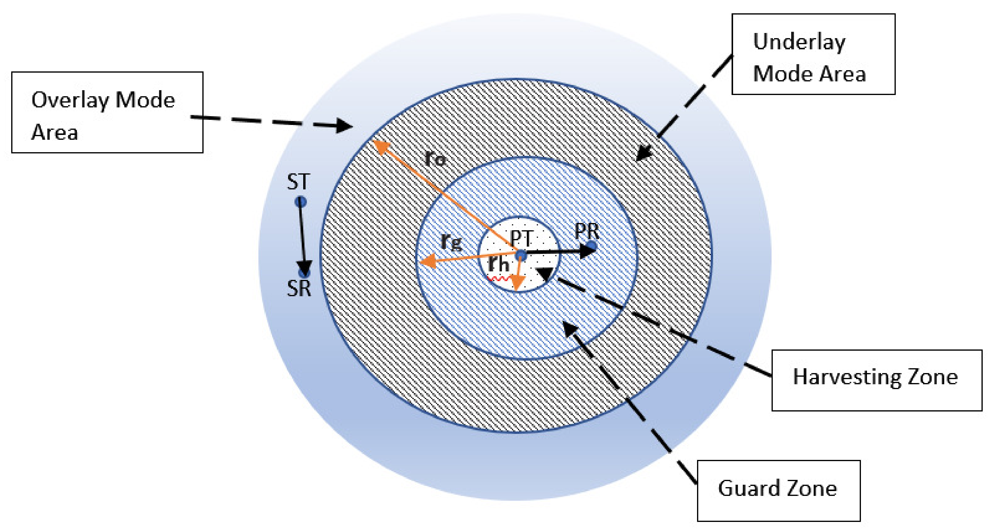
- For the CRN with mobile energy harvesting ST, this paper is the first attempt to maximize the efficiency of m-channel allocation by dividing the coverage area into overlay mode area, underlay mode area, and harvesting and guard zones for the throughput analysis given the hybrid underlay-overlay scheme under the interference constraint.
- (2)
- For allocation of multiple channels, to prioritize STs, a new metric for each of ST is proposed based on their current energy level, number of channels they need (having more channels means having higher priority), and harvesting capability to assign channels. For the energy constraint, at every time slot, the energy level of each ST is controlled; if exceeds sensing + transmission energy, it performs sensing and decides to transmit based on whether idle channels are found. Nodes lying outside of coverage area of a PT channel owner can use the channel simultaneously with the channel owner. As a result, interference is assumed to be negligible. Therefore, this ST does not need to sense the channel, so energy is only consumed for transmission, producing considerable energy savings.
- (3)
- Simulations show that channel distribution performance is markedly improved by harvesting energy from ambient RF signals when assigning channels to SUs for both the proposed new metric and the maximum independent sets (MIS) of the graph when hybrid zone partitioning is applied. In addition, as harvesting depends on number of users located in the defined HZ (density of SUs), the more users located in the HZ, the more energy can be harvested, which enables the storage of more energy, thereby increasing channel distribution performance.
2. Materials and Methods
2.1. System Model
- (1)
- harvesting mode if it is inside the HZ of an active PT and does not have enough energy for transmission;
- (2)
- overlay transmitting mode if it has enough energy and is located outside of the coverage area of an active PT, or anywhere if the PT is inactive;
- (3)
- underlay transmitting mode if it has enough energy and is located inside the coverage area of an active PT by reducing transmitting power; and
- (4)
- idle mode if it is located inside the guard zone, or is neither fully charged nor inside any of the HZs.
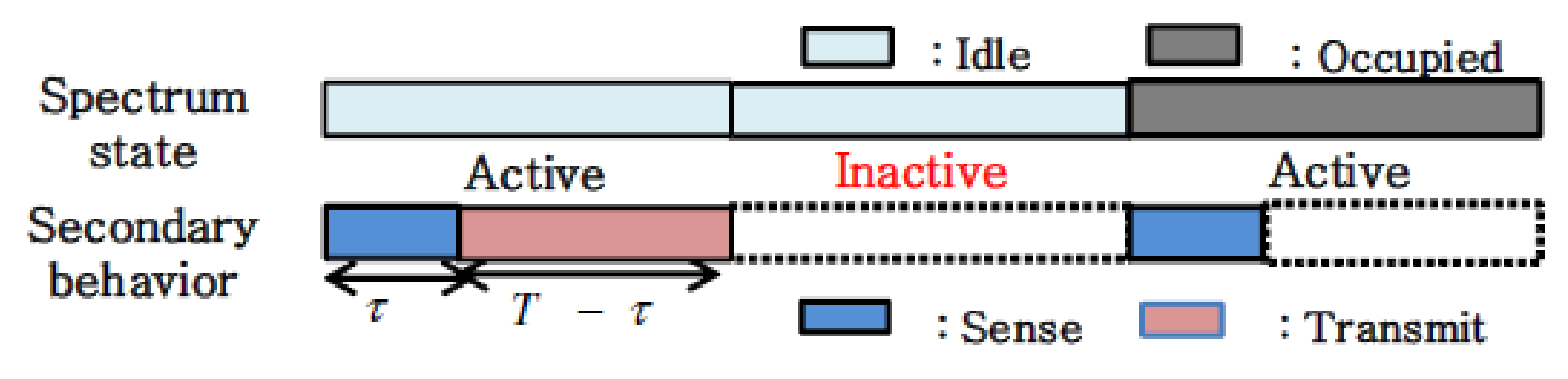
- ST decides whether to sense spectrum based on the residual energy in the battery.
- If the ST cannot make sensing and is located in any HZ of an active PT, the ST harvests energy from RF signals or stays idle if it is located in the underlay, overlay mode area, or in the guard zone.
- If the ST can make spectrum sensing, it does so, and the result is obtained.
- When the licensed spectrum is found as free, ST makes transmission in overlay mode. So, the resulting energy at the end of time slot t is: = – –
- When the licensed spectrum is tested and found to be busy, ST harvests energy from RF signals if it is located in the HZ, transmits in overlay mode if it is located outside of interference range, or transmits in underlay mode if it is located in the underlay mode area.(overlay mode, no need to sense as ST is located outside of interference region)Prioritization of STs based on their energy level, whether they can harvest energy and number of channels they need are critical during distribution of channels to STs.
- Having higher initial energy enables an ST to sense channels and transmit data over longer time slots as their energy will be wasted in a longer period.
- If an ST is located in HZ of a PT, which means it can harvest energy, it will have more energy on the fly which means more chance to sense channels and make transmission.
- Having more than one wireless interface for transmission, meaning it has multi-channel usage ability, enables an ST to make transmission over more channels at the same time, which improves throughput of the total system because aim of a cognitive system is to maximize channel utilization.
- denotes PriorityMeasure of (i) for channel j;
- shows whether (i) is located in the guard zone of (j) (owner of channel j), which is 1 if located outside the guard zone and 0 otherwise as (i) can never transmit using channel j;
- EL(i) is the current energy level of (i) in joules and (EL) is maximum energy level of all . So, component of the equation regarding energy level is normalized by maximum energy;
- CN(i) indicates the number of channels needed by (i). Therefore, for instance, if number of channels required is 3, the contribution to PriorityMeasure will be 0.9; if 1, it will be 0.3. This component is appended to the metric, because, as mentioned before, contribution of owning higher number of channels on PriorityMeasure should be higher; and
- finally, is 1 if (i) is located in the HZ of the (j), and 0 otherwise. As an that can harvest should be located in guard zone by definition, this coefficient is separately added to the PriorityMeasure.
2.2. Greedy and Proposed Algorithms
2.2.1. Greedy Algorithm
2.2.2. Proposed Algorithm Using MIS of Interference Graph
2.2.3. Proposed Algorithm Using Proposed Metric for Allocation:
3. Results and Discussion
- is the transmission power of primary transmitter ;
- is the distance between primary transmitter and primary receiver ;
- is the tolerable SINR ratio threshold at (SINR value when total interference is which is the tolerable interference threshold at the primary receiver ), so that the corresponding primary receiver can successfully receive primary transmitter packets;
- S is the total number of secondary users;
- is the transmission power of secondary user ;
- is the distance between secondary user and the primary receiver ; and
- is additive white Gaussian noise for the receiver, with a zero mean.
- Number of PTs is 2, which means the number of available channels is 2 and the number of idle channels varies randomly between 0 and 2.
- The Poisson distribution density of STs was about 0.0015 in the 100 × 100 marea around the PT.
- Average estimated percentage of STs in HZ is about 21%, according to Equation (10).
- Figure 4 shows that with increasing SINR (outage) threshold values, the channel distribution fairness factor calculated using Equation (9) increases from 0.0387 to about 0.039, which is close to the upper limit of ChDistFairness of 0.05. This proves that as the number of STs inside the 100 × 100 m area increases, the co-channel interference between neighboring nodes increases and, additionally, more STs exist in the guard zone of a PT, which means they could not make use of those channels. As such, ChDistFairness is not much affected by SINR changes.
- As the average percentage of STs in HZ was 21%, which implies almost every 1 of 5 STs can harvest energy, ChDistFairness improves, especially in the first three time slots since some STs harvest energy and use it for their sensing and transmission.
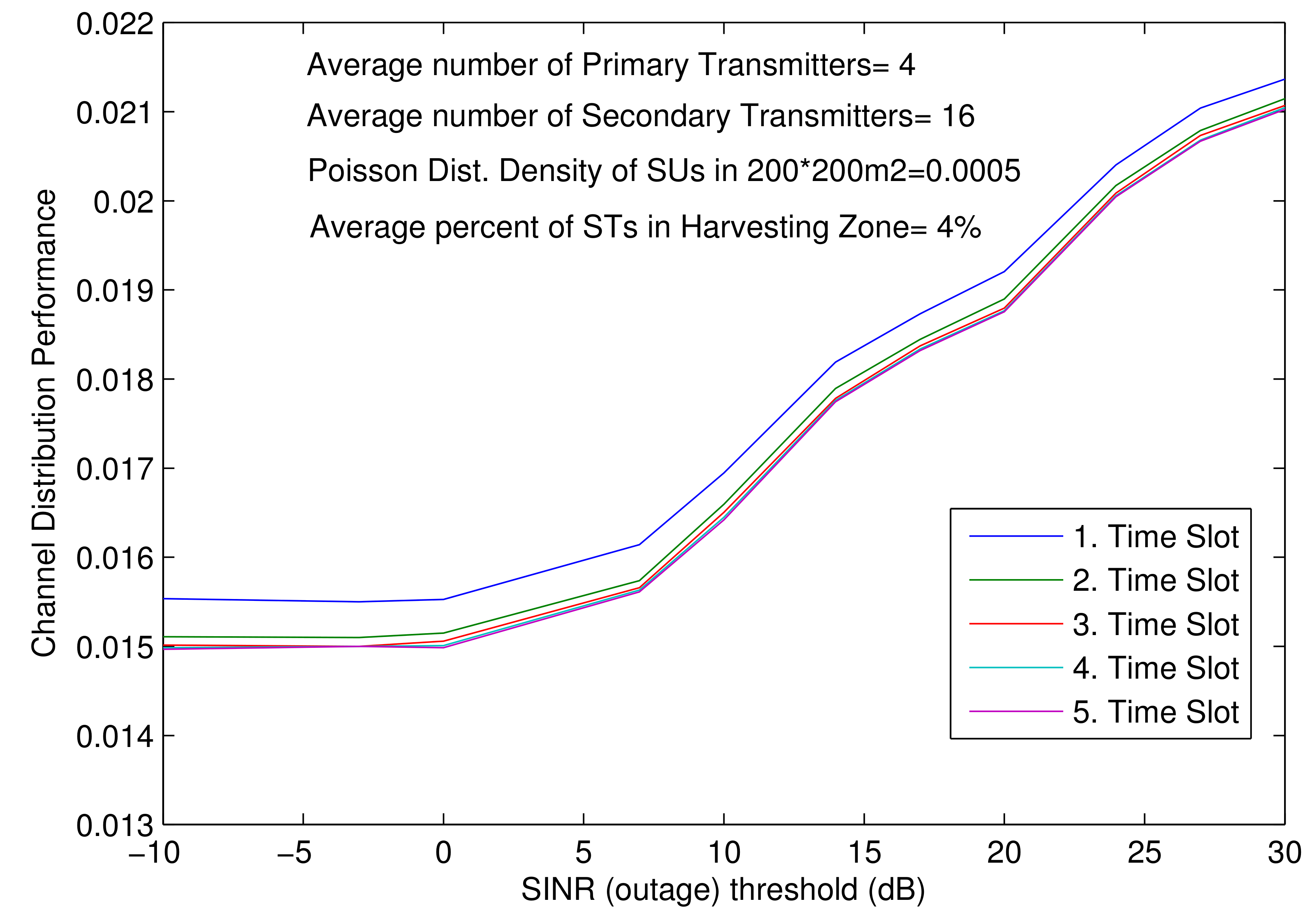
- The total number of PTs and STs are increased to 4 and 16, respectively. That means number of available channels is 4 and number of idle channels varies randomly between 0 and 4.
- However, compared to Experiment 1, the density of STs in a 200 × 200 marea distributed around the PT decreases to about 0.0005, and the percentage of harvestable STs decreases to about 4%.
- As depicted in Figure 5, with increasing SINR (outage) threshold values, ChDistFairness increases from 0.015 to about 0.021, which is far below the upper limit of 0.05, which is quite good.
- Although the total number of STs increases, the number of STs inside the 100 × 100 m area falls, thereby decreasing in the guard zone, as well. Since the distance between STs increases (because of density decrease), the average number of neighbors of STs decreases, thereby reducing the co-channel interference between neighboring nodes, too, which allows more channels to be shared.
- When the SINR (outage) threshold increases, the interference constraint on PTs becomes more dominant, so ChDistFairness drops accordingly.
- The average percentage of STs in the HZ is about 4%; and, due to those harvesting nodes, ChDistFairness still improves, especially in the first, second, and third time slots due to utilizing the harvested energy.
- The total number of PTs and STs are increased again to 6 and 26, respectively.
- The density of the STs distributed around the PT decreases to about 0.0005 in 300 × 300 myet, which means the percentage of harvesting STs falls to around 3%.
- As shown in Figure 6, with increasing SINR (outage) threshold values, ChDistFairness values vary from 0.0065 to about 0.015, which seems to be better than the previous results. This is because number of available channels (PTs) increases from 4 to 6.
- As the total number of STs increases, the number of STs inside the 100 × 100 m area decreases, thereby decreasing in the guard zone, as well, which results in an increase in the probability of channels usage.
- As STs move away from each another due to the density decrease, the co-channel interference drops, which means more channels can be shared. Again, as expected, channel distribution performance worsens (so ChDistFairness raises) when the SINR (outage) threshold increases, accordingly, due to the interference constraint.
- In accordance with the ST harvesting capability in HZ, which is about 3%, ChDistFairness drops again with increasing time slots.
- The density of the STs distributed around the PT is decreased to about 0.0002 in 400 × 400 m.
- The total number of PTs and STs are 6 and 25.
- Figure 7 shows again that with increasing SINR (outage) threshold values, the ChDistFairness values vary between 0.0065 and about 0.016.
- Similar to previous results, due to density decrease, the number of STs inside the guard zone decreases. That is why the co-channel interference drops and results in more channels to be allocated.
- Again, as expected, ChDistFairness increases when the SINR (outage) falls. In accordance with the harvesting capability of STs in the HZ, which is about 3%, ChDistFairness falls again with progressive time slots.
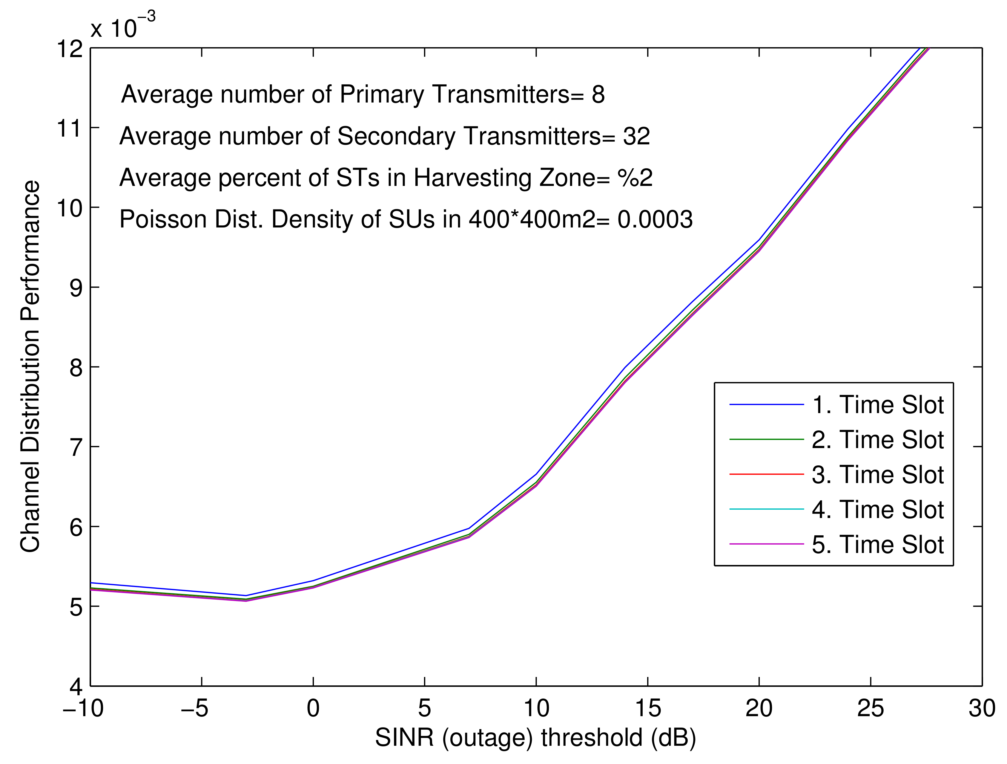
- The numbers of PTs and STs are further increased to 8 and 32.
- The Poisson distribution density of STs is about 0.0003 in the 400 ×400 marea around the PT.
- Average estimated percentage of STs in HZ is about 2%.
- Comparison of the results in Figure 8 with the previous experiment shows that ChDistFairness varies between 0.005 and 0.013, which indicates better performance. Even though the average percentage of STs in HZ is a little lower and density is slightly higher, more channels seem to be allocated since more channels are available to be shared due to the increase in the number of PTs from 6 to 8.
- On the other hand, it is observed that ChDistFairness does not much change against increasing time slots. This is because number of total STs increases and, even if harvesting is applied, this cannot improve ChDistFairness much since number of available channels per ST is more restricted.
- In addition, average percentage of STs in the harvesting zone decreases from 3% to 2%, which reduces energy harvesting capability that results in decreasing on improvement of ChDistFairness.
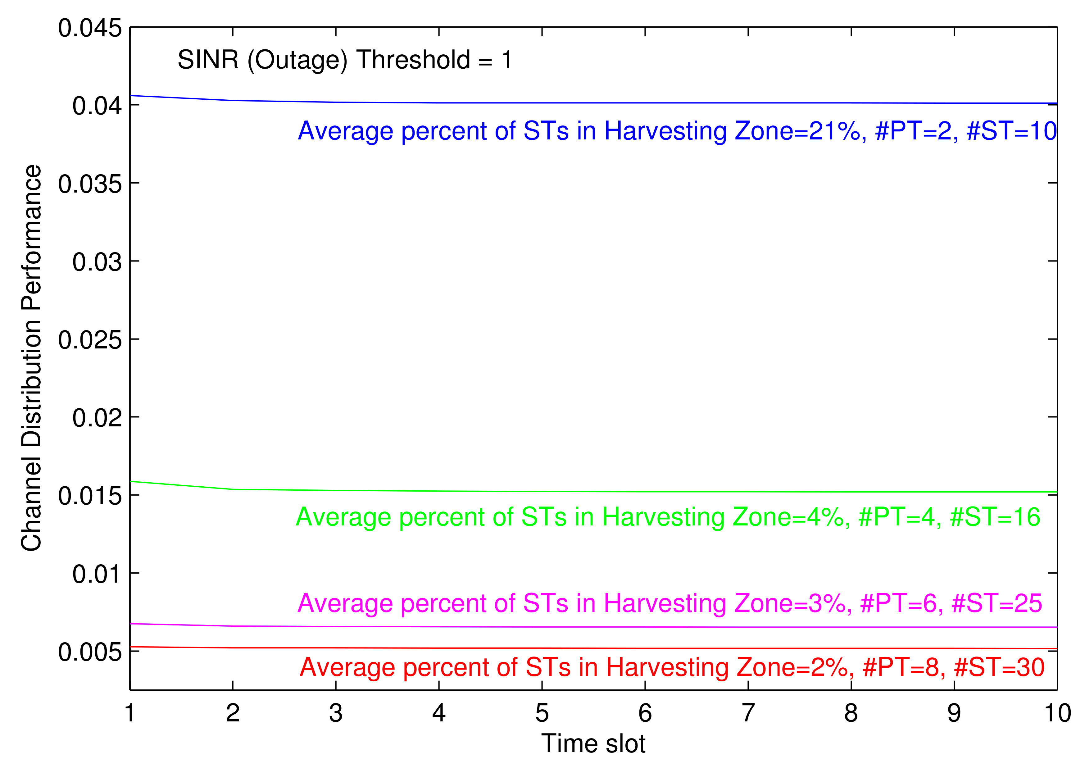
- Average percentages of STs in the HZ is 21%, and the number of PTs and STs are 2 and 20, respectively, when the SINR (outage) threshold fixed to 1.
- Average percentages of STs in the HZ is 4%, and the number of PTs and STs are 4 and 16, respectively, when the SINR (outage) threshold fixed to 1.
- Average percentages of STs in the HZ is 3%, and the number of PTs and STs are 6 and 25, respectively, when the SINR (outage) threshold fixed to 1.
- Average percentages of STs in the HZ is 2%, and the number of PTs and STs are 8 and 30, respectively, when the SINR (outage) threshold fixed to 1.
- The results are depicted in Figure 9. For each of the cases, ChDistFairness decreases (improves) in the first 3–4 time slots as a result of harvesting capability. This effect happens most in the case with the highest percentage of STs in HZ of 21% (blue curve) where harvesting is more utilized than the others (next experiment depicts this effect more clearly).
- The channel distribution performance is best when the number of PTs is highest (PTs = 8, red curve) as the highest number of channels are available for STs.
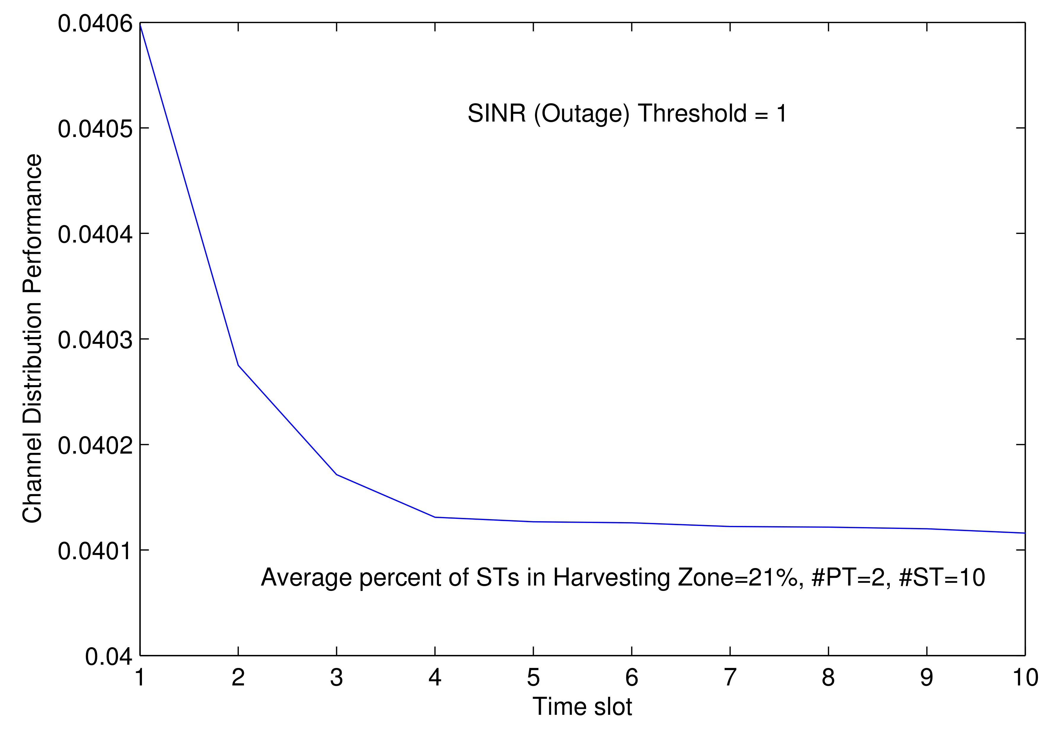
- Average percentage of STs in HZ is fixed to 21% and number of PTs and STs are 2 and 10, respectively, when the SINR (outage) threshold fixed to 1.
- As shown in Figure 10, ChDistFairness decreases until the fifth time slot via harvesting capability when the SINR (outage) threshold is fixed to 1.
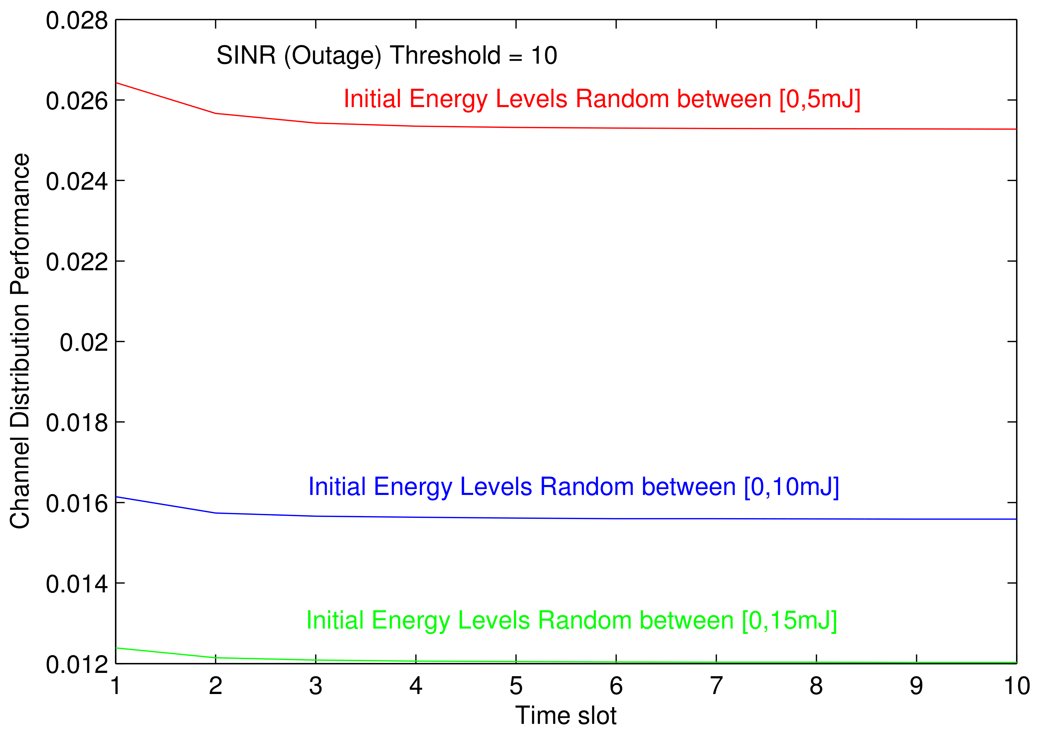
- Three different experiments run. In the first experiment, at each run, initial energy levels are randomly set between (0, 5 mj); in the second experiment, they are set between (0, 10 mj), and at third experiment, they are set between (0, 15 mj) sequentially, which means possible maximum values are 5 mj, 10 mj, and 15 mJ.
- The SINR (outage) threshold is fixed to 10.
- The average percentage of STs in the HZ is fixed to 4%.
- As expected, for the case with lowest initial energy level between (0, 5 mj), STs are able to allocate fewer channels since their energy runs short of fastest. The results are shown in Figure 11.
- With increasing initial energy level, STs have more ability to utilize channels against time slots since energy is consumed slower. So, results given in blue seem better than red.
- In the third case, when initial energy level is set between (0, 15 mj), ChDistFairness results become the best since STs are most capable to utilize channels because of having more energy.
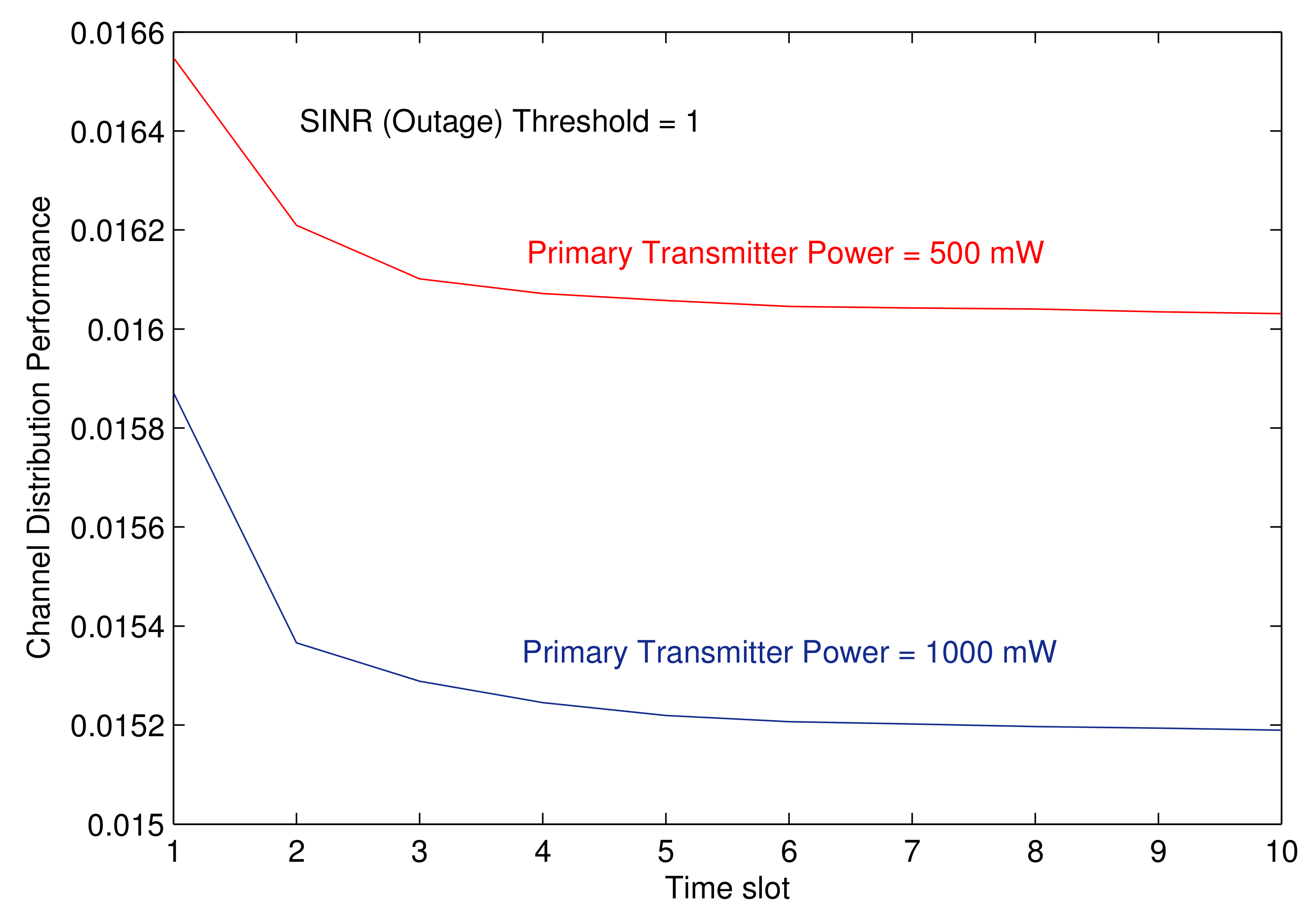
- PT transmission power level is set to 1000 mW when the SINR (outage) threshold fixed to 1.
- PT transmission power level is set to 500 mW when the SINR (outage) threshold fixed to 1.
- Results are depicted in Figure 12. When PT power is higher, which means the numerator in Equation (7) is higher, the sum of interferences in the denominator is allowed to be higher when keeping the same SINR (outage) threshold value. Therefore, STs being allowed to create more interference on primary receiver have more opportunity to utilize channels, which results in higher channel distribution performance (lower ChDistFairness).
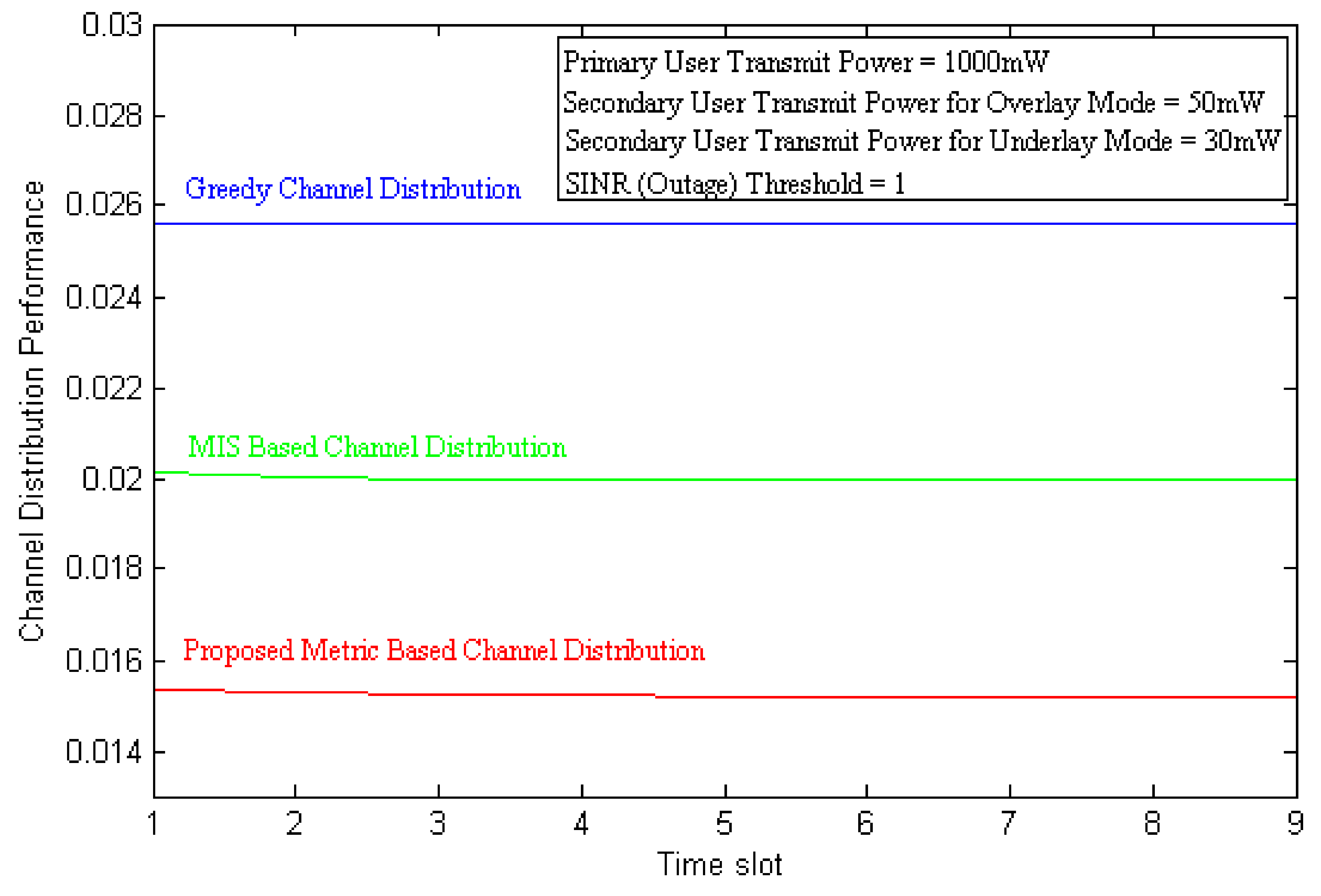
- PT transmission power, ST overlay, and underlay mode transmission powers are set to 1000 mW, 50mW, and 30 mW, respectively, when the SINR (outage) threshold fixed to 1 and number of PTs and STs are 4 and 16, respectively.
- PT transmission power, ST overlay, and underlay mode transmission powers are set to 1000 mW, 50 mW, and 30 mW, respectively, when the SINR (outage) threshold fixed to 100 and number of PTs and STs are 4 and 16, respectively.
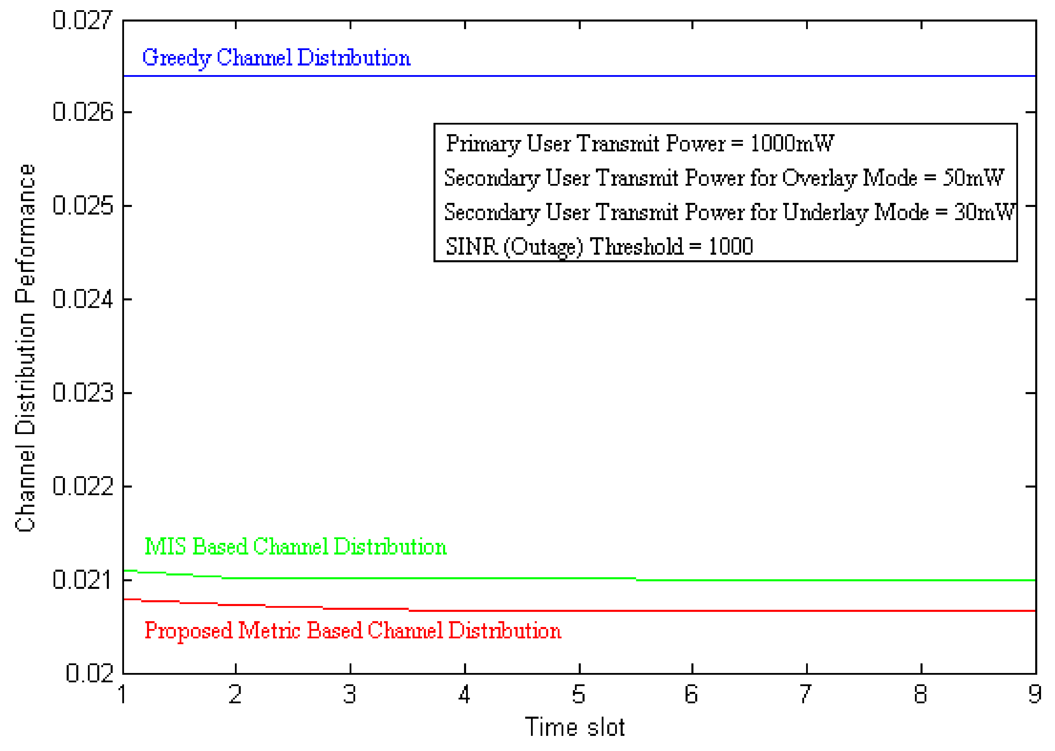
- PT transmission power, ST overlay, and underlay mode transmission powers are set to 1000 mW, 50 mW, and 30 mW, respectively, when the SINR (outage) threshold fixed to 1000 and number of PTs and STs are 4 and 16, respectively.
- Figure 13, Figure 14 and Figure 15 depict the results for differing SINR (outage) threshold values. As shown, for each of these cases, the performance of the greedy algorithm (blue curve) is the worst since it does not take advantage of energy harvesting mechanism nor make prioritization-based allocation.
- The proposed algorithm using MIS-based allocation (green curve) performs better allocation than the greedy method since STs store energy via harvesting.
- Finally, as the red curve depicts, the proposed algorithm using the proposed metric given by Equation (6) performs the best (the lowest ChDistFairness values between the 3 algorithms). This is because this algorithm allocates channels taking into account prioritization of those nodes having more initial energy, more harvesting capability, and also multi-channel usage ability, thus owning higher metric value, which ensures more channels be utilized against increasing time slots.
4. Conclusions
- with more initial energy,
- having energy harvesting capability, and
- equipped with multi-channel transmission ability
Funding
Acknowledgments
Conflicts of Interest
Abbreviations
| 3GPP | 3rd Generation Partnership Project |
| Tolerable SINR ratio threshold at primary receiver | |
| ChDistFairness | Channel Distribution Fairness |
| CN | ChannelNeed |
| CR | Cognitive Radio |
| CRN | Cognitive Radio Networks |
| CWPCN | Cognitive wireless powered communication network |
| Distance between primary transmitter and primary receiver | |
| Distance between secondery user and primary receiver | |
| DOAJ | Directory of open access journals |
| EL | Energy Level |
| EH | Energy Harvesting |
| HPPP | Homogeneous Poisson Point Process (HPPP) |
| HZ | Harvesting Zone |
| MAC | Medium Access Control |
| MDP | Markov Decision Process |
| MDPI | Multidisciplinary Digital Publishing Institute |
| MIS | Maximum Independent Set |
| N | Toal number of STs in Harvesting Zone |
| LD | linear dichroism |
| LTE | Long-term evolution technology |
| PM | PriorityMeasure |
| PR | Primary Receiver |
| Prob | Outage Probability |
| PT | Primary Transmitter |
| PU | Primary User |
| P | Tolerable interference threshold at the primary receiver for |
| Rat | Ratio of STs in Harvesting Zone |
| RF | Radio-frequency |
| SINR | Signal to Interference plus Noise Ratio |
| ST | Secondary Transmitter |
| SU | Secondary User |
| T | Total number of STs |
| TLA | Three letter acronym |
References
- Hasan, Z.; Boostanimehr, H.; Bhargava, V.K. Green Cellular Networks: A Survey, Some Research Issues and Challenges. IEEE Commun. Surv. Tutor. 2011, 13, 524–540. [Google Scholar] [CrossRef]
- Cai, L.X.; Poor, H.V.; Liu, Y.; Luan, T.H.; Shen, X.; Mark, J.W. Dimensioning network deployment and resource management in green mesh networks. Wirel. Commun. 2011, 18, 58–65. [Google Scholar] [CrossRef]
- Cuadras, A.; Gasulla, M.; Ferrari, V. Thermal Energy Harvesting Through Pyroelectricity. Sens. Actuators A Phys. 2010, 158, 132–139. [Google Scholar] [CrossRef]
- Kolodzy, P.; Avoidance, I. Spectrum policy task force report. Fed. Commun. Comm. 2002, 40, 147–158. [Google Scholar]
- Liu, X.; Zhu, Y.; Kong, L.; Liu, C.; Gu, Y.; Vasilakos, A.V.; Wu, M. CDC: Compressive data collection for wireless sensor networks. Proc. Annu. Int. Conf. Mob. Comput. Netw. MOBICOM 2015, 26, 2188–2197. [Google Scholar]
- Mitola, J.; Maguire, G.Q. Cognitive radio: Making software radios more personal. IEEE Pers. Commun. Mag. 1999, 6, 13–18. [Google Scholar] [CrossRef]
- Chang, Y.C.; Wang, N. Legal system for the development of marine renewable energy in China. Renew. Sustain. Energy Rev. 2017, 75, 192–196. [Google Scholar] [CrossRef]
- Zhang, L.; Liang, Y.-C.; Xin, Y. Joint beamforming and power allocation for multiple access channels in cognitive radio networks. IEEE J. Sel. Areas Commun. 2008, 26, 38–51. [Google Scholar] [CrossRef]
- Liang, Y.-C.; Zeng, Y.; Peh Hoang, A.T. Sensing throughput tradeoff for cognitive radio networks. EEE Trans. Wirel. Commun. 2008, 7, 1326–1337. [Google Scholar] [CrossRef]
- Lee, S.; Huang, K.; Zhang, R. Cognitive energy harvesting and transmission from a network perspective. In Proceedings of the IEEE International Conference on Communication Systems (ICCS), Singapore, 21–23 November 2012; pp. 225–229. [Google Scholar]
- Plata, D.M.M.; Reátiga, A.G.A. Evaluation of energy detection for spectrum sensing based on the dynamic selection of detection-threshold. Procedia Eng. 2012, 35, 135–143. [Google Scholar] [CrossRef]
- Stoopman, M.; Keyrouz, S.; Visser, H.J.; Philips, K.; Serdijn, W.A. Co-design of a CMOS rectifier and small loop antenna for highly sensitive RF energy harvesters. IEEE J. Solid-State Circuits 2014, 49, 622–634. [Google Scholar] [CrossRef]
- Zhang, Y.; Han, W.; Li, D.; Zhang, P.; Cui, S. Power versus spectrum 2-D sensing in energy harvesting cognitive radio networks. IEEE Trans. Signal Process. 2015, 63, 6200–6212. [Google Scholar] [CrossRef]
- Lee, S.; Zhang, R.; Huang, K. Opportunistic wireless energy harvesting in cognitive radio networks. IEEE Trans. Wirel. Commun. 2013, 12, 4788–4799. [Google Scholar] [CrossRef]
- Yin, S.; Qu, Z.; Li, S. Achievable throughput optimization in energy harvesting cognitive radio systems. IEEE J. Sel. Areas Commun. 2015, 33, 407–422. [Google Scholar] [CrossRef]
- Pratibha Li, K.H.; Teh, K.C. Optimal spectrum access and energy supply for cognitive radio systems with opportunistic RF energy harvesting. IEEE Trans. Veh. Technol. 2017, 66, 7114–7122. [Google Scholar] [CrossRef]
- Park, S.; Kim, H.; Hong, D. Cognitive radio networks with energy harvesting. IEEE Trans. Wirel. Commun. 2013, 12, 1386–1397. [Google Scholar] [CrossRef]
- Park, S.; Hong, D. Optimal spectrum access for energy harvesting cognitive radio networks. IEEE Trans. Wirel. Commun. 2013, 12, 6166–6179. [Google Scholar] [CrossRef]
- Yang, Z.; Ding, Z.; Fan, P.; Karagiannidis, G.K. Outage performance of cognitive relay networks with wireless information and power transfer. IEEE Trans. Veh. Technol. 2016, 65, 3828–3833. [Google Scholar] [CrossRef]
- Wang, Z.; Chen, Z.; Xia, B.; Luo, L.; Zhou, J. Cognitive relay networks with energy harvesting and information transfer: Design, analysis, and optimization. IEEE Trans. Wirel. Commun. 2016, 15, 2562–2576. [Google Scholar] [CrossRef]
- Hoang, D.T.; Niyato, D.; Wang, P.; Kim, D.I. Opportunistic channel access and RF energy harvesting in cognitive radio networks. IEEE J. Sel. Areas Commun. 2014, 32, 2039–2052. [Google Scholar] [CrossRef]
- Zheng, G.; Ho, Z.; Jorswieck, E.A.; Ottersten, B. Information and energy cooperation in cognitive radio networks. IEEE Trans. Signal Process. 2014, 62, 2290–2303. [Google Scholar] [CrossRef]
- Yin, S.; Zhang, E.; Qu, Z.; Yin, L.; Li, S. Optimal cooperation strategy in cognitive radio systems with energy harvesting. IEEE Trans. Wirel. Commun. 2014, 13, 4693–4707. [Google Scholar] [CrossRef]
- Pratibha, M.; Li, K.H.; Teh, K.C. Channel selection in multichannel cognitive radio systems employing RF energy harvesting. IEEE Trans. Veh. Technol. 2016, 65, 457–462. [Google Scholar] [CrossRef]
- Bae, Y.H.; Baek, J.W. Achievable throughput analysis of opportunistic spectrum access in cognitive radio networks with energy harvesting. IEEE Trans. Commun. 2016, 64, 1399–1410. [Google Scholar] [CrossRef]
- Park, S.; Heo, J.; Kim, B.; Chung, W.; Wang, H.; Hong, D. Optimal Mode Selection for Cognitive Radio Sensor Networks with RF Energy Harvesting. In Proceedings of the IEEE 23rd International Symposium on Personal, Indoor and Mobile Radio Communications-(PIMRC), Sydney, NSW, Australia, 9–12 September 2012; pp. 2155–2159. [Google Scholar]
- Barroca, N.; Ferro, J.M.; Borges, L.M.; Tavares, J.; Velez, F.J. Electromagnetic Energy Harvesting for Wireless Body Area Networks with Cognitive Radio Capabilities. In Proceedings of the URSI Seminar Portuguese Committee, Lisbon, Portugal, 1–4 November 2012. [Google Scholar]
- Senthuran, S.; Anpalagan, A.; Das, O. Throughput analysis of opportunistic access strategies in hybrid underlay—Overlay cognitive radio networks. IEEE Trans. Wirel. Commun. 2012, 11, 2024–2035. [Google Scholar] [CrossRef]
- Usman, M.; Koo, I. Access strategy for hybrid underlay-overlay cognitive radios with energy harvesting. IEEE Sensors J. 2014, 14, 3164–3173. [Google Scholar] [CrossRef]
- Ma, B.; Cheung, M.H.; Wong, V.W.S.; Huang, J. Hybrid overlay/underlay cognitive Femtocell networks: A game theoretic approach. IEEE Trans. Wirel. Commun. 2015, 14, 3259–3270. [Google Scholar] [CrossRef]
- Lee, S.; Zhang, R. Cognitive wireless powered network: Spectrum sharing models and throughput maximization. IEEE Trans. Cogn. Commun. Netw. 2015, 1, 335–346. [Google Scholar] [CrossRef]
- Kim, J.; Lee, H.; Song, C.; Oh, T.; Lee, I. Sum throughput maximization for multi-user MIMO cognitive wireless powered communication networks. IEEE Trans. Wirel. Commun. 2017, 16, 913–923. [Google Scholar] [CrossRef]
- Zheng, K.; Liu, X.; Liu, X.; Zhu, Y. Hybrid Overlay-Underlay Cognitive Radio Networks With Energy Harvesting. IEEE Trans. Commun. 2019, 67, 4669–4682. [Google Scholar] [CrossRef]
- Petar, P.; Hiroyuki, Y.; Kentaro, N.; Rocco, T.; Ramjee, R. Opportunistic Interference Cancellation in Cognitive Radio Systems. IEEE Int. Symp. New Front. Dyn. Spectr. Access Netw. 2007, 472–475. [Google Scholar]
- Liu, X.; Zheng, K.; Liu, X.-Y.; Wang, X.; Zhu, Y. Hierarchical cooperation improves delay in cognitive radio networks with mobile secondary nodes. IEEE Trans. Mob. Comput. 2019, 12, 2871–2884. [Google Scholar] [CrossRef]
- Awin, F.A.; Alginahi, Y.M.; Abdel-Raheem, E.; Tepe, K. Technical Issues on Cognitive Radio-Based Internet of Things Systems: A Survey. IEEE Access 2019, 7, 97887–97908. [Google Scholar] [CrossRef]
- Awin, F.; Abdel-Raheem, E.; Tepe, K. Blind Spectrum Sensing Approaches for Interweaved Cognitive Radio System: A Tutorial and Short Course. IEEE Commun. Surv. Tutor. 2019, 21, 238–259. [Google Scholar] [CrossRef]
- Le, T.; Mayaram, K.; Fiez, T. Efficient far-field radio frequency energy harvesting for passively powered sensor networks. IEEE J. Solid-State Circuits 2008, 43, 1287–1302. [Google Scholar] [CrossRef]
- Miao, M.; Danny, T. Cross-Layer Throughput Optimization in Cognitive Radio Networks with SINR Constraints. Int. J. Digit. Multimed. Broadcast. 2010, 10. [Google Scholar] [CrossRef]
- Zhao, Q.; Sadler, B.M. A survey of dynamic spectrum access. IEEE Signal Process. Mag. 2007, 24, 79–89. [Google Scholar] [CrossRef]
- Yilmaz, Y.; Guo, Z.; Wang, X. Sequential joint spectrum sensing and channel estimation for dynamic spectrum access. IEEE J. Sel. Areas Commun. 2014, 32, 2000–2012. [Google Scholar] [CrossRef]
- Chung, W.; Park, S.; Lim, S.; Hong, D. Optimal Transmit Power Control for Energy-Harvesting Cognitive Radio System. In Proceedings of the IEEE 78th Vehicular Technology Conference (VTC Fall), Las Vegas, NV, USA, 2–5 September 2013; Volume 32, pp. 1–5. [Google Scholar]
- Piñuela, M.; Mitcheson, P.D.; Lucyszyn, S. Ambient RF Energy Harvesting in Urban and Semi-Urban Environments. IEEE Trans. Microw. Theory Tech. 2013, 61, 2715–2726. [Google Scholar] [CrossRef]
- Karaca, H.M.; Kurt, T.; Dicle, S.Z.; Anarim, E. Auction-Based Throughput Maximization in Cognitive Radio Networks Under Interference Constraint. Wirel. Pers. Commun. 2013, 72, 1259–1275. [Google Scholar] [CrossRef]
- Pei, Y.; Liang, Y.C.; Teh, K.C.; Li, K.H. Energy-efficient design of sequential channel sensing in cognitive radio networks: Optimal sensing strategy, power allocation, and sensing order. IEEE J.Sel. Areas Commun. 2011, 29, 1648–1659. [Google Scholar] [CrossRef]
- Luo, Y.; Pu, L.; Wang, G.; Zhao, Y. RF Energy Harvesting Wireless Communications: RF Environment, Device Hardware and Practical Issues. Sensors 2019, 19, 3010. [Google Scholar] [CrossRef] [PubMed]
- Nguyen, D.K.; Jayakody, D.N.K.; Chatzinotas, S.; Thompson, J.S.; Li, J. Wireless Energy Harvesting Assisted Two-Way Cognitive Relay Networks: Protocol Design and Performance Analysis. IEEE Access 2017, 5, 21447–21460. [Google Scholar] [CrossRef]


| Input Parameters: | • Interference graph G; |
| • Channel needs of each secondary user; | |
| • Total number of channels available in the spectrum pool; | |
| • Transmission power of primary and secondary users; | |
| • Initial energy levels of ST users; | |
| • Definitions of overlay, underlay, and guard zones; | |
| • Primary and secondary overlay/underlay transmission power levels; | |
| • Sensing power; | |
| • Slot duration; | |
| • Sensing period; | |
| • Transmission period; | |
| • Signal to interference plus noise ratio. | |
| Output Parameter: | • Channel distribution fairness index. |
| Step 1: | • Create 4 matrices for overlay, underlay, harvesting and guard zones, respectively, each of which consists of values 1 or 0. Rows of matrices consist of STs, and columns consist of PTs (which means channels). Value of matrix element is set to 1 if ST is located in corresponding zone, otherwise 0. |
| • Create interference matrices for each ST towards each PT for overlay and underlay transmission modes, using overlay and underlay transmission powers of each ST and distance between ST and PT [44]. | |
| • Calculate energy levels necessary for sensing, overlay mode, and underlay mode transmissions, respectively, using Equation (2). | |
| Step 2: | • Sort secondary users (SUs) by their degrees in the interference graph (degree = number of neighboring nodes). |
| Step 3: | • Select the least used channel from available channels. |
| Step 4: | • For the selected channel, select the node with the lowest degree from nodes not checked yet. In case two nodes having the same degree, select the one that is farther from the primary user owning that channel. |
| Step 5: | • Sense if the channel found in step 3 is idle or busy. |
| If channel==idle, then | |
| • check if the node found in step 4 has enough energy for overlay transmission for the channel selected in step 3. | |
| If yes, then | |
| • calculate the total interference on the PT owning the channel if the channel is assigned. | |
| If it does not exceed the necessary interference threshold for the given SINR and neighbor nodes of the node have not already obtained this channel, then | |
| • assign the channel to the node, | |
| • update the energy level by subtracting sensing and overlay transmission energies from the initial energy, | |
| • update the lists of used channels of affected nodes, | |
| • if a node obtained the number of required channels, remove it from main interference graph, and proceed to step 7, | |
| else, | |
| • check if the node lies outside the interference range of the PT owning the channel selected in step 3 and if it has enough energy for overlay transmission. | |
| If yes, then | |
| •calculate the total interference on the PT owning the channel if the channel is assigned. | |
| If the SINR condition is satisfied and the neighbor nodes of the node were not obtained by this channel already, then | |
| • assign the channel to the node and update the energy level by subtracting the overlay transmission energy from the initial energy. | |
| else, if the node lies inside the interference range of the PT, check if the node has enough energy for underlay transmission. | |
| If yes, calculate the total interference on the channel owner PT if the channel is assigned.If the SINR is satisfied, then | |
| • assign the channel to the node and update the energy level by subtracting sensing and underlay transmission energies from the initial energy, | |
| • update the lists of used channels of affected nodes. If a node obtained all the required channels, remove it from main interference graph. | |
| Step 6: | •Check if all nodes are checked towards the selected channel. |
| If not, then | |
| continue with step 4 by selecting another node. | |
| else, | |
| continue with step 3, selecting another available channel from list. If all channels have been checked, proceed to step 7. | |
| Step 7: | • Check if the number of nodes in the main interference graph is greater than 1. |
| If yes, then | |
| • check if no more channel can be assigned due to energy insufficiency. | |
| If yes, then finish. | |
| else, | |
| • return to step 2, | |
| else, finish. |
| Input Parameters: | • Interference graph G; |
| • Channel needs of each secondary user; | |
| • Total number of channels available in the spectrum pool; | |
| • Transmission power of primary and secondary users; | |
| • Initial energy levels of ST users; | |
| • Definitions of overlay, underlay, and guard zones; | |
| • Primary and secondary overlay/underlay transmission power levels; | |
| • Sensing power; | |
| • Slot duration; | |
| • Sensing period; | |
| • Transmission period; | |
| • Signal to interference plus noise ratio. | |
| Output Parameter: | • Channel distribution fairness index. |
| Step 1: | • Create 4 matrices for overlay, underlay, harvesting and guard zones, respectively, each of which consists of values 1 or 0. Rows of matrices consist of STs, and columns consist of PTs owning channels. Value of matrix element is set to 1 if ST is located in corresponding zone, otherwise 0. |
| • Create interference matrices for each ST towards each PT for overlay and underlay transmission modes, using overlay and underlay transmission powers of each ST and distance between ST and PT [44]. | |
| • Calculate energy levels necessary for sensing, overlay mode, and underlay mode transmissions, respectively, using Equation (2). | |
| Step 2: | • Create sub graph Gi, if i = 1, Gi = G. |
| Step 3: | • Calculate the MIS and delete it from the subgraph. |
| Step 4: | • Select the least used channel from available channels and sense if the channel is idle or busy. |
| If channel==idle, then | |
| • proceed to step 5; | |
| else, | |
| • proceed to step 6. | |
| Step 5: | • Get each member node of MIS one by one and check if it has enough energy for overlay transmission for the channel checked in step 4. |
| If yes, then | |
| • calculate the total interference on the PT owning the channel if the channel is assigned. | |
| If not exceeding the necessary interference threshold for a given SINR and neighbor nodes of the node have not already obtained this channel, then | |
| • assign the channel to the node, | |
| • update the energy level by subtracting sensing and overlay transmission energies from the initial energy, | |
| • update the lists of used channels of affected nodes. If a node obtained all the required channels, remove it from the main interference graph and proceed to step 7. | |
| Step 6: | • Check if the node lies outside the interference range of the PT owning the channel selected in step 3 and if it has enough energy for overlay transmission. |
| If yes, then | |
| • calculate the total interference on the PT owning the channel if the channel is assigned. | |
| If the SINR is satisfied and none of the neighbor nodes have been already obtained this channel, then | |
| • assign the channel to the node and update the energy level by subtracting sensing and overlay transmission energies from the initial energy, | |
| • update the lists of used channels of affected nodes. If a node obtained all the required channels, remove it from main interference graph. | |
| else, | |
| • check if the node has enough energy for underlay transmission. | |
| If yes, then | |
| • calculate the total interference on the PT owning the channel if the channel is assigned, | |
| If the SINR is satisfied and none of the neighbor nodes have been already obtained this channel, then | |
| • assign the channel to the node and update the energy level by subtracting sensing and underlay transmission energies from the initial energy. | |
| • update the lists of used channels of affected nodes. If a node obtained all the required channels, remove it from main interference graph. | |
| Step 7: | • check if all MIS nodes were checked towards the selected channel. |
| If yes, then | |
| • go to step 4 to select another available channel. If all channels have already been checked, proceed to step 8 | |
| else, | |
| • go to step 5. | |
| Step 8: | • Check if the number of nodes in the main interference graph is greater than 1. |
| If yes, then | |
| • check if no more channel can be assigned due to energy insufficiency. | |
| If yes, then finish. | |
| else, | |
| • return to step 2, | |
| else, finish. |
| Input Parameters: | • Interference graph G; |
| • Channel needs of each secondary user; | |
| • Total number of channels available in the spectrum pool; | |
| • Transmission power of primary and secondary users; | |
| • Initial energy levels of ST users; | |
| • Definitions of overlay, underlay, and guard zones; | |
| • Primary and secondary overlay/underlay transmission power levels; | |
| • Sensing power; | |
| • Slot duration; | |
| • Sensing period; | |
| • Transmission period; | |
| • Signal to interference plus noise ratio. | |
| Output Parameter: | • Channel distribution fairness index. |
| Step 1: | • Create 4 matrices for overlay, underlay, harvesting and guard zones, respectively, each of which consists of values 1 or 0. Rows of matrices consist of STs, and columns consist of PTs owning channels. Value of matrix element is set to 1 if ST is located in corresponding zone, otherwise 0. |
| • Create interference matrices for each ST towards each PT for overlay and underlay transmission modes, using overlay and underlay transmission powers of each ST and distance between ST and PT [44]. | |
| • Calculate energy levels necessary for sensing, overlay mode, and underlay mode transmissions, respectively, using Equation (2). | |
| Step 2: | • Select the least used channel from available channels and calculate the proposed metric given in Equation (6) for each ST towards that channel, and sort the list in descending order of metric. |
| Step 3: | • Sense if the channel is idle or busy. |
| If channel==idle, then | |
| • proceed to step 5; | |
| else, | |
| • proceed to step 6. | |
| Step 4: | • Get the node with highest metric of the list -which is not checked yet- and check if it has enough energy for overlay transmission for the channel checked in step 3. |
| If yes, then | |
| • calculate the total interference on the PT owning the channel if the channel is assigned. | |
| If not exceeding the necessary interference threshold for a given SINR and neighbor nodes of the node have not already obtained this channel, then | |
| • assign the channel to the node, | |
| • update the energy level by subtracting sensing and overlay transmission energies from the initial energy, | |
| • update the lists of used channels of affected nodes. If a node obtained all the required channels, remove it from main interference graph and proceed to step 6. | |
| Step 5: | • Get the node with highest metric of the list -which is not checked yet- and check if it lies outside the interference range of the PT owning the channel selected in step 3. |
| If yes, then | |
| • check if the node has enough energy for overlay transmission. | |
| If yes, then | |
| • calculate the total interference on the PT owning the channel if the channel is assigned. | |
| If not exceeding the necessary interference threshold for a given SINR and neighbor nodes of the node have not already obtained this channel, then | |
| • assign the channel to the node, | |
| • update the energy level by subtracting sensing and overlay transmission energies from the initial energy. | |
| • update the lists of used channels of affected nodes. If a node obtained all the required channels, remove it from main interference graph. | |
| else, | |
| • check if the node has enough energy for underlay transmission. | |
| If yes, then | |
| • calculate the total interference on the PT owning the channel if the channel is assigned. | |
| If not exceeding the necessary interference threshold for a given SINR and neighbor nodes of the node have not already obtained this channel, then | |
| • assign the channel to the node, | |
| • update the energy level by subtracting sensing and underlay transmission energies from the initial energy. | |
| • update the lists of used channels of affected nodes. If a node obtained all the required channels, remove it from main interference graph. | |
| Step 6: | • Check if all STs are tested towards the selected channel. |
| If yes, then | |
| • continue with step 3 by selecting another available channel. If all channels have already been checked, proceed to step 7. | |
| • else, | |
| • return to step 4. | |
| Step 7: | • Check if the number of nodes in the main interference graph is greater than 1. |
| If yes, then | |
| • check if no more channel can be assigned due to energy insufficiency. | |
| If yes, then finish. | |
| else, | |
| • return to step 2 and restart channel allocation with new updated energy levels. | |
| else, finish. |
| Symbol | Description | Value |
|---|---|---|
| T | Slot Duration | 1 ms |
| Sensing Duration | 0.002 ms | |
| T - | Transmission Duration | 0.098 ms |
| E | Initial Energy | random value in range [0, max(E)] |
| P | Sensing Power | 110 mW |
| P | Overlay Transmit Power | 50 mW |
| P | Underlay Transmit Power | 30 mW |
| SINR | Signal to Interference Plus Noise Ratio | dB |
| E | Harvested Energy | mJ |
| r | Radius of Harvesting Zone | 33 m |
| r | Radius of Guard Zone | 75 m |
| N | Guassion Noise with Zero Mean | 10 mW |
| P | Primary User’ s Power | 1 W |
| e | Residual Energy at the Beginning of Time Slot t | mJ |
| e | Energy Necessary to Make Overlay Transmission | 5.12 mJ |
| e | Energy Necessary to Make Underlay Transmission | 3.16 mJ |
| Harvesting Conversion Efficiency | 0.75 | |
| n | Max Number of Available Channels for each ST | 3 |
| Path-loss Exponent | 0.75 |
© 2020 by the author. Licensee MDPI, Basel, Switzerland. This article is an open access article distributed under the terms and conditions of the Creative Commons Attribution (CC BY) license (http://creativecommons.org/licenses/by/4.0/).
Share and Cite
Karaca, H.M. Throughput Optimization of Multichannel Allocation Mechanism under Interference Constraint for Hybrid Overlay/underlay Cognitive Radio Networks with Energy Harvesting. Electronics 2020, 9, 330. https://doi.org/10.3390/electronics9020330
Karaca HM. Throughput Optimization of Multichannel Allocation Mechanism under Interference Constraint for Hybrid Overlay/underlay Cognitive Radio Networks with Energy Harvesting. Electronics. 2020; 9(2):330. https://doi.org/10.3390/electronics9020330
Chicago/Turabian StyleKaraca, Hakan Murat. 2020. "Throughput Optimization of Multichannel Allocation Mechanism under Interference Constraint for Hybrid Overlay/underlay Cognitive Radio Networks with Energy Harvesting" Electronics 9, no. 2: 330. https://doi.org/10.3390/electronics9020330
APA StyleKaraca, H. M. (2020). Throughput Optimization of Multichannel Allocation Mechanism under Interference Constraint for Hybrid Overlay/underlay Cognitive Radio Networks with Energy Harvesting. Electronics, 9(2), 330. https://doi.org/10.3390/electronics9020330