1. Introduction
The aviation industry has seen a gradual increase in the application of software in airborne systems. The software’s failure to perform the designated task, however, can have undesirable consequences, such as equipment damage and risk to human life. The Boeing 737 crashes in 2018 and 2019 have made this concern even more pronounced. Hence, strict verification processes must be followed while creating safety-critical software so as to ensure their reliability and security.
The Radio Technical Commission for Aeronautics (RTCA) released the DO-178B Airworthiness Certification Standard [
1] in 1992 to illustrate the software lifecycle and provide guidance on the development process of airborne software. However, with steady growth in the scale and complexity of airborne software, the number of components, modules, and interfaces required for an enhanced development process has also increased. Such substantial increase brings with it a higher probability of software failure with unpredictable consequences. In 2011, the RTCA passed the DO-178C standard [
2], together with four development technology supplements. DO-333 [
3] is the formal supplement for DO-178C, to guide the application of formal methods in software development and verification processes.
In recent years, research on the formal verification of airborne software has received extensive attention, and several formal methods have been applied in the industry. Souyris et al. show how the Airbus has been integrating several abstract interpretation-based analysis tools into the development process of avionics software products [
4]. Odile and Thomas et al. both discuss how Airbus applies model-checking techniques on the Safety Critical Application Development Environment (SCADE) to the validation and verification process of avionics systems [
5,
6]. NASA applies theorem proving, model checking, and abstract interpretation techniques to achieve different verification objectives in its case study on the Dual-Channel Flight Guidance System [
7]. There are some case studies ([
8,
9,
10]) that focus on applying formal methods to artifacts and objectives at a certain software verification stage.
With reference to relevant cases, it is observed that the application of formal verification for airborne software in the industry was mostly focused on applying SCADE to the software development cycle or using a single formal method to verify the artifacts at a certain software development stage. At present, there is a lack of systematic guidance for the application of formal methods for airborne software verification, and several methods and tools that have been successfully applied in other industries is yet to be introduced here.
This paper proposes a methodology for formal analysis and verification of airborne software based on DO-333 to provide guidance in integrating formal methods in software development and verification. It showcases the Air Data Computer (ADC) software to illustrate how this research’s methodology could be applied and how formal methods and tools have to be selected to verify specific objectives. We hope that the readers can derive inspiration from our case. The contributions of this study can be presented as follows:
• Present a comprehensive formal verification methodology for the airborne software.
According to the software lifecycle defined for DO-178C, this study divides verification activity into three parts: requirements and design, source code, and executable object code. The methodology used summarizes the commonly used formal analysis and verification methods in each phase and enumerates some frequently used mature formal models and tools. This research covers the entire A-level software verification process defined in DO-333, which can guide the formal analysis and verification of airborne software.
• Demonstrate the practical application of formal methods using the ADC software
For the software discussed in this study, all the requirements were formalized with Event-B and objectives like compliance and traceability were verified by Rodin. This was followed by the extraction of formal specifications from the behavior model and compiling with VCC annotations to automatically verify the software at the source code level. Furthermore, a static analysis tool called PolySpace was used to detect runtime errors in the source code level. For verification of the binary code, we analyzed the minimum subset of the source code structure to verify the traceability of the executable object code to the source code. By using this approach, the correctness of the verification of the executable object code was converted into formal analysis in the source code level. After formal verification and review of the ADC software, a total of 16 errors were identified. This shows that the formal method is an effective verification method.
The rest of the paper is organized as follows:
Section 2 provides a brief introduction of airworthiness certification standards and formal methods;
Section 3 describes the methodology used, providing advice on how to apply formal methods to the software development process (based on DO-333);
Section 4 illustrates ADC software’s formal verification process and shows how to use formal methods to verify specific objectives; and
Section 5 concludes the work and discusses further research.
2. Background
2.1. Airworthiness Certification Standards
To establish development guidelines for airborne systems and equipment software that ensure that it could perform its intended safety functions according to airworthiness requirements, the RTCA published the DO-178B (Software Considerations in Airborne Systems and Equipment Certification) in 1992. In DO-178B, the safety conditions are divided into five levels (A-E level) based on their effects on the aircraft, crew, and passengers. However, the increasing size and complexity of modern avionics software have raised questions on the viability of the DO-178B. The guideline takes little or no account of current development and validation methods, such as model-based development and object-oriented techniques. Therefore, in 2011, the RTCA passed the DO-178C standard and prepared four supplementary documents: tool identification (DO-330), model-based development and verification (DO-331), object-oriented technology (OOT) and related technologies (DO-332), and formal methods (DO-333).
DO-333 is a supplementary document for the DO-178C. It discusses the use of formal methods in the software lifecycle for software produced following the DO-178C. DO-333 is used to describe how verification objectives, activities, explanatory texts, and software lifecycle data in DO-178C should be addressed when formal methods are used as part of the software lifecycle. This includes artifacts that could be expressed using formal notations and the verification foundation derived from them. It guides the applicants and certification or approval authorities in facilitating the use of formal methods. Based on the DO-333, the formal methods used in this paper carry out formal verification of the objectives defined in DO-178C.
2.2. Formal Methods
Formal methods are mathematically based techniques for the specification, development, and verification of the software aspects of digital systems. They use mathematical methods for all phases of the system, so that the behavior of the system can be accurately described and characterized [
11]. Further extensions are supported based on formal models, thus ensuring that the properties of the developed system meet requirements and determine the correctness and robustness of the design. Formal methods usually involve the following three types of activities [
12]:
1. System modeling: formal model is an abstract representation of software for analysis, simulation, and code generation.
2. Formal specification: formal specification is a description of some properties that the system must satisfy.
3. Formal verification: formal verification is used to verify that the formal model of the system satisfies the formal specification.
Formal verification methods can typically be classified into three categories: model checking, theorem proving, and abstract interpretation.
Model checking explores all possible behaviors of a formal model to determine whether a specified property is satisfied. If the property does not hold, the model checking algorithm generates a counterexample. Model checking can realize fully automated verification with high efficiency. However, the increase of scale and complexity of the software causes great difficulties in the modeling and may lead to the explosion of state space.
Theorem proving models the system and the specification as logic formulae and proves the satisfaction relation between them by deductive proof calculus. It uses inductive methods to describe the behavior and attributes of the program, which can well solve the “state explosion” problem. However, theorem proving cannot be automated at present. When encountering complex problems with a large scale of code, the proof work needs to be completed with the help of the user’s heuristics.
Abstract interpretation is used to construct semantics-based analysis algorithms for the automatic, static, and sound determination of dynamic properties of infinite-state programs. The essence of abstract interpretation is to sacrifice accuracy for computational feasibility and efficiency, which will limit its application.
The drawbacks of formal methods can be worked on by continuous development and application; however, it is not the focus of this paper. Based on existing technology, this paper discusses the formal technologies and tools that can be applied to airborne software and provides guidance for industrial applications.
3. Methodology and Process
The DO-333 standard was introduced in 2011 as a supplement to the formal verification method of DO-178C for airworthiness certifications. For specific verification objectives in DO-178C, it refers to artifacts that could be expressed using formal notations and the verification evidence derived from them.
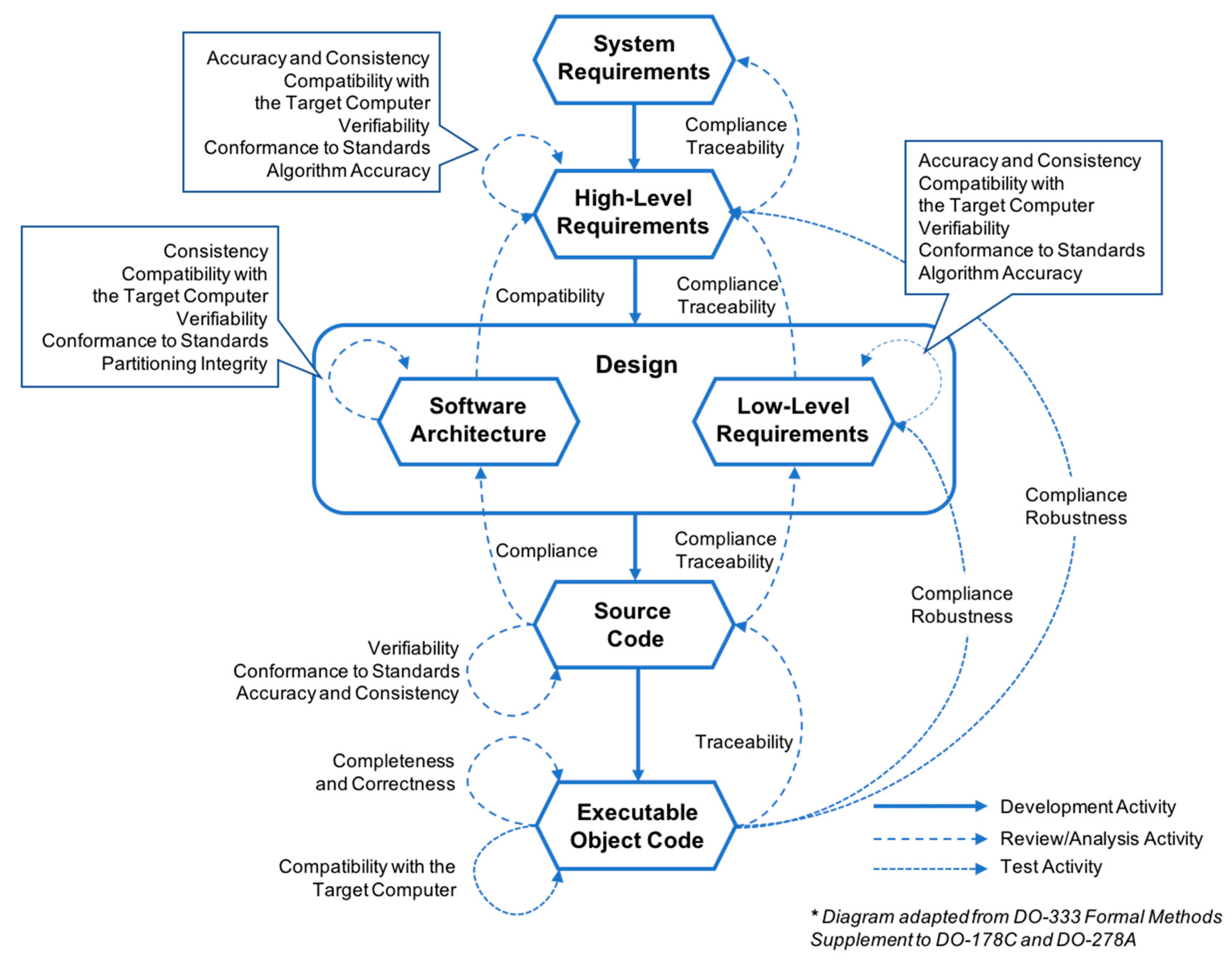
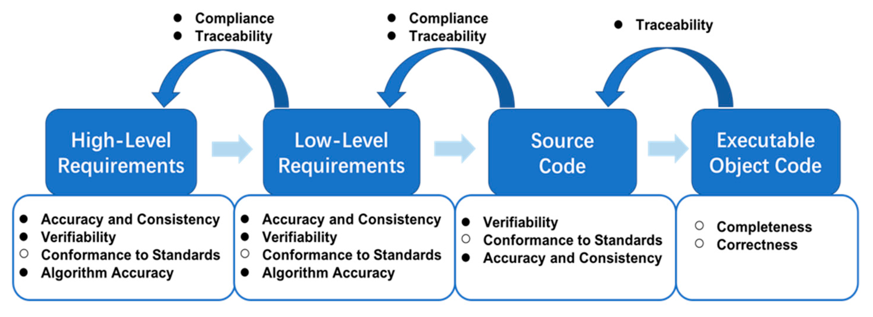
Figure 1 depicts the data items, development activities, and verification activities involved in the requirement, design, and coding processes of A-level software.
Figure 1 lists the objectives of each verification activity, including accuracy, consistency, compliance, and traceability, among others. Consistency means there is no logical conflict between two data items (requirements or source code). Compliance refers to the satisfaction relationship between two data items; for example, the compliance of high-level requirements (HLR) to system requirements. Traceability refers to the association between data items; it usually refers to two-way tracking relationships. For example, traceability between HLR and Low-Level Requirements (LLR). All HLR are developed into more detailed LLR, while all LLR can correspond to the HLR. Based on accurate and unambiguous formal descriptions of software lifecycle data items, formal methods can prove (or combine with review and other methods to prove) whether the data items meet the above verification objectives.
It is imperative to mention that formal analysis may be applied to a small portion of the verification objectives or as the primary source of evidence for accomplishing the desired development and verification objectives. Some objectives may be fully compliant with formal methods, while others may require additional verification, such as testing in an integrated target computer. Thus, review, analysis and testing are also presented as means of attaining these verification objectives.
According to
Figure 1, we divide the entire verification process into three parts: requirements and design, source code, and executable object code. The following sections will summarize some of the formal techniques and methods that can be applied.
3.1. Formal Analysis of Requirements and Design
As shown in
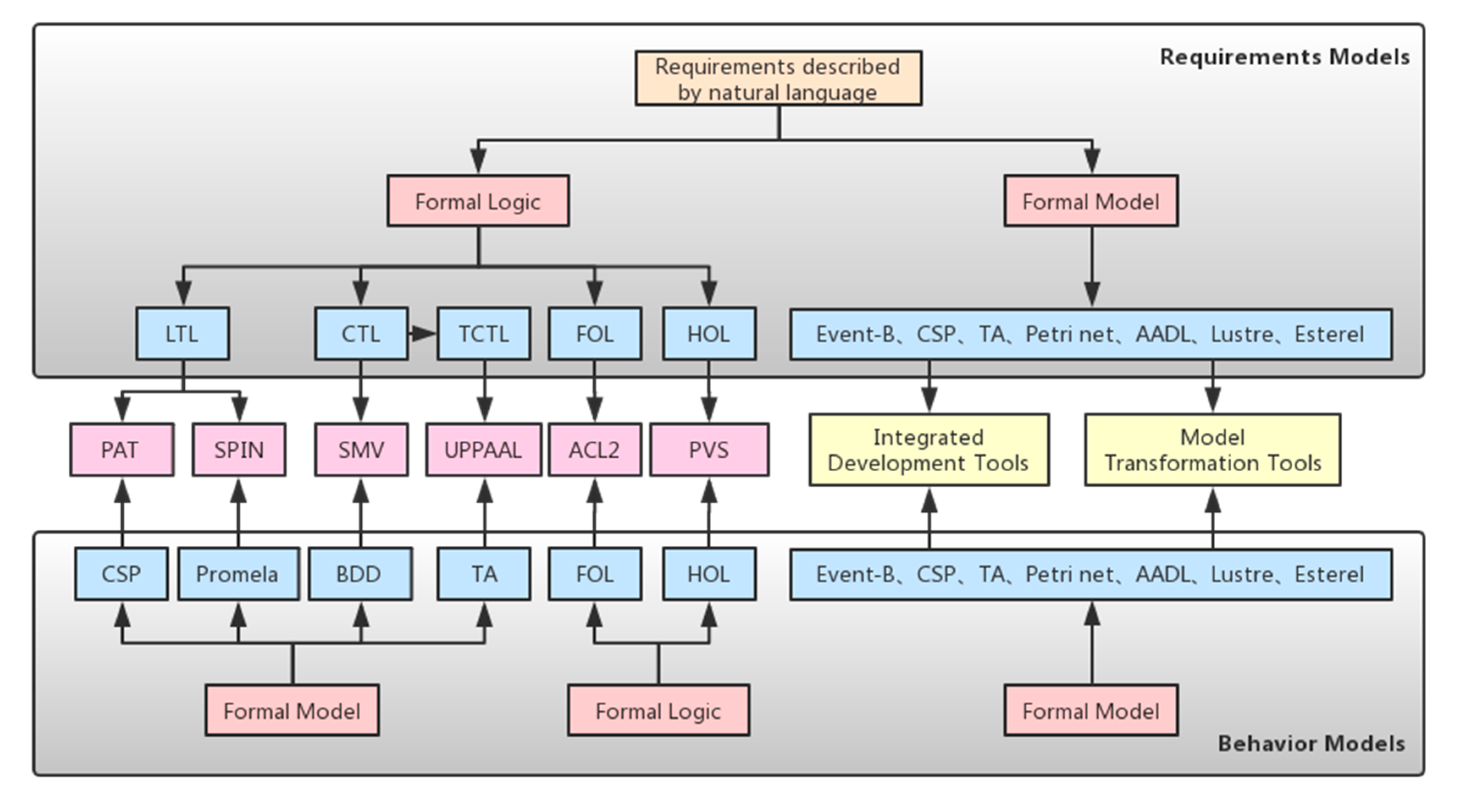
Figure 2, the main idea of formal analysis of requirements and design is to respectively establish behavior and requirements models to depict the system to be verified and the properties that the system must satisfy. There are two main formal analysis methods for this process: model checking and theorem proving.
Model checking is used to verify whether the behavior model can satisfy the specifications written in temporal logic, like LTL, CTL, TCTL [
13], etc. This logic focuses on the sequence and timing of events, and can describe a wide range of properties, such as safety, reachability, aliveness, fairness, and real-time. For formal specifications written using temporal logic, the behavior model needs to be described with the corresponding formal language, like CSP [
14], Promela [
15], BDD [
16], TA [
17], etc. If the model and specifications are formalized correctly, the model checker will automatically determine whether the property is satisfied. Applicable model checkers for the selected temporal logic and modeling language include PAT [
18], SPIN [
19], SMV [
20], UPPAAL [
21], etc. Their relationship is shown in
Figure 2.
Theorem proving verifies formal specifications written in predicate logic, like FOL, HOL [
22], etc. In the theorem prover, requirement specifications are written into theorems, and then they are automatically or semi-automatically proved by adding defined axioms and induction rules. Commonly used theorem provers are ACL2 [
23], PVS [
24], Isabelle/HOL [
25], Coq [
26], etc. Among them, the ACL2 specification language is based on FOL, while PVS, Isabelle/HOL, and Coq are based on HOL.
There are certain integrated development tools that not only provide a modeling environment, but also have certain embedded model checkers or theorem provers to directly verify the model’s accuracy. The most familiar integrated development environment is SCADE, which can cover all development phases from requirements to code, including requirement modeling, model checking, simulation, formal verification, code generation, and more [
27]. Therefore, it has been widely used in industrial applications. In addition, there are some open-source platforms that support embedded formal verification tools, like Rodin, the platform for Event-B modeling [
28].
When the models are built by different formal languages, model transformation needs to be considered. The idea of model transformation can be used for shortcomings between two models. On the one hand, when a model is not sufficient to describe certain properties, it can be converted into another model to realize system modeling more efficiently. On the other hand, a model written in a semi-formal language needs to be converted into a formal model for model checking, like SysML [
29], AADL [
30], etc.
The above mentioned formal methods and tools are commonly used in academia and industry. With continuous research and development of formal methods, many novel formal languages and tools have appeared and are widely used, like NuSMV [
31], CCS [
32], RSML
−e [
33], etc. We do not list them in
Figure 2, but in the following sections, we will cite a few research papers and show their applications.
3.2. Formal Analysis of Source Code
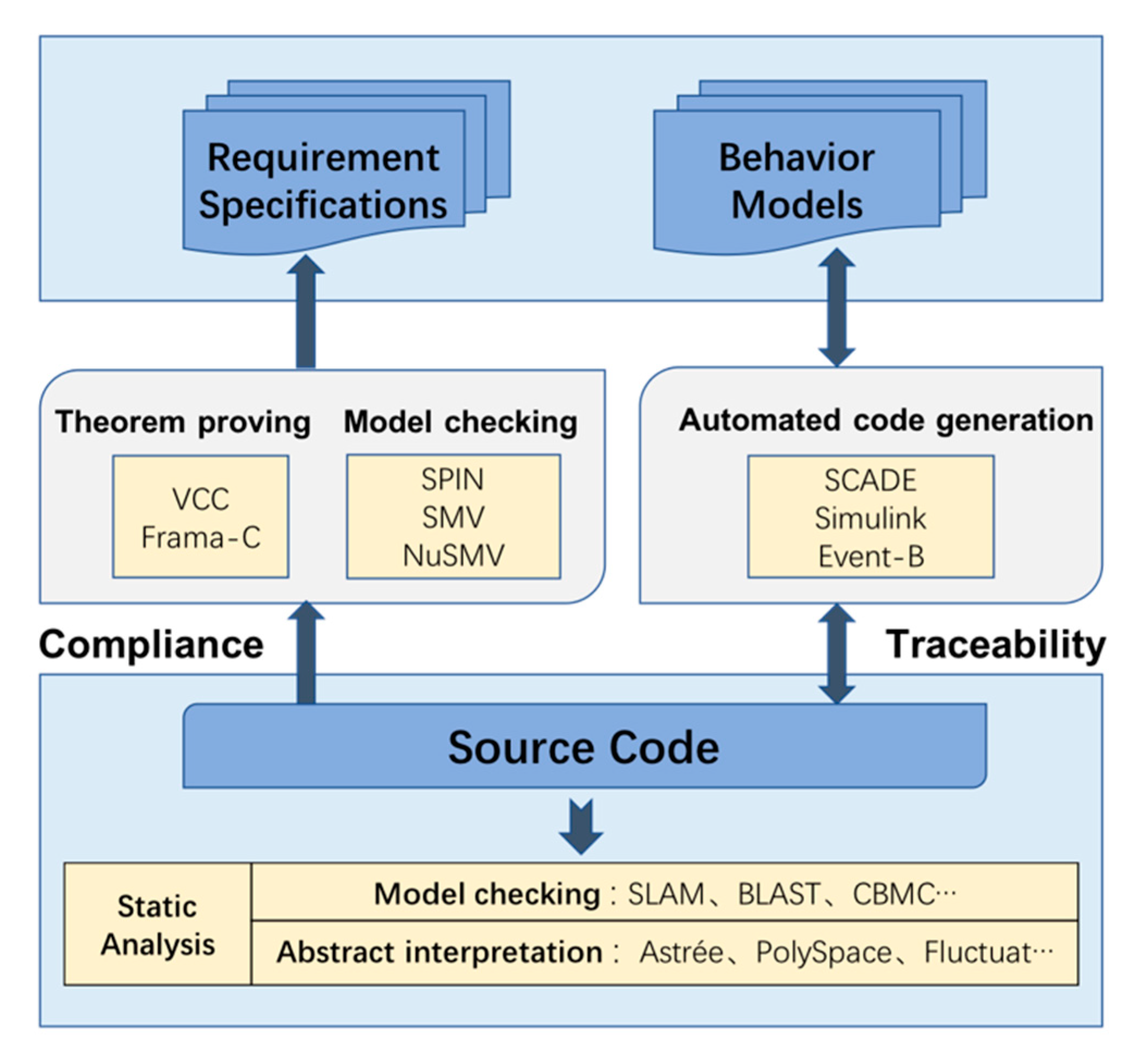
Figure 3 shows that the verification of source code can be divided into the compliance of source code to requirement specifications, traceability between source code and behavior models, and static analysis of source code. This paper focused on a single target language, namely C, for the reason that most airborne software is written in it.
Theorem proving and model checking offer a solution to verify compliance of source code with requirement specifications. To apply theorem proving, the specifications need to be extracted as pre- and post-conditions and then converted to annotations in the C program; finally, deductive reasoning is used to verify the annotations. Here, we list two theorem proving tools that are commonly used in the industry: VCC [
34] and Frama-C [
35]. Another verification method is based on model checking. By constructing a formal model from the source code, and using the temporal logic (primarily LTL and CTL) to represent requirements specifications, model checking tools can provide a counter-example path when the system is not satisfied. There are many model checkers such as SPIN [
36], SMV [
20], NuSMV [
37], etc., which can be used to achieve the objective of compliance of source code with requirement specifications.
In the development process based on formal methods, this is an excellent method to improve the model utilization rate by directly converting the verified formal models into source code. Furthermore, development cycles can be shortened significantly with automatic code generation. SCADE from Esterel Technologies, Simulink [
38] from Mathworks, and many other tools like Rodin have built-in code generators that can transform behavior models into equivalent C code. The code generated from the formal model ensures traceability from the source code to the behavior model.
The static analysis tool used does not actually need to run the program in the target hardware, but rather analyzes control and data flow, combined with abstract interpretation and symbolic execution techniques, to check for data overflow, divide-by-zero, out-of-bounds array access, and other run-time errors in the source code, and realize the accurate location of the problems [
39]. Commonly used static analysis tools include Astre’ e [
40], PolySpace [
41], Fluctuat [
42] (based on abstract interpretation), SLAM [
43], BLAST [
44], and CBMC [
45] (based on model checking), among others.
3.3. Formal Analysis of Executable Object Code
Figure 1 shows that the verification objectives of the executable object code (EOC) are chiefly achieved by testing and assisted by reviews and analysis, as indicated in DO-178C. Since DO-178C allows formal verification to replace certain forms of testing, this section summarizes the formal methods that can be used to supplement or replace test activities.
1. Static Analysis of Worst-case Execution Time and Stack Usage
Worst-case execution time (WCET) and stack usage must be analyzed at the EOC level because compilers, linkers, and some hardware features may have a non-negligible impact on them. Based on the information flow of the program, the static analysis method estimates the WCET of the program according to the characteristics of the target processor, rather than directly executing on the hardware. The tools aiT [
46] from AbsInt GmbH, and Bound-T [
47] from Tidorum Ltd. both use this approach. Similarly, StackAnalyzer [
48] which is also from AbsInt GmbH and Bound-T, can compute the worst-case stack usage of the program in its binary form, which contributes to proving that execution of the program will not cause stack overflow.
2. Verification of Property Preservation Between Source and Executable Object Code
FM.6.7, item f in DO-333, states, “By verifying the correctness of the translation of source to object code, formal analysis performed at the Source Code level against high or low-level requirements can be used to infer correctness of the Executable Object Code against high or low-level requirements.” Therefore, the main work at the binary code level is focused on verifying the traceability of the EOC to the source code. There are two mainstream approaches to verify correctness of the translation from source code to EOC.
In the verification process of ADC software, the method of analyzing the minimum subset of the source code structure is used to verify traceability from the EOC to source code. The specific process is described in
Section 4.4.
The formal verification of airborne software is a hot research topic in the field of safety-critical software. Many researchers have carried out relevant work, and some of their academic papers and industrial reports are cited in this paper. We list the formal methods or tools used in their studies and associate the verification work in these reports with the verification objectives in DO-333. According to the methodology of this paper, we divide all verification work into three stages; the final results are shown in
Table 1.
4. Formal Verification of Air Data Computer Software
In this section, we conduct a complete formal verification process for Air Data Computer (ADC) software, which comprehensively demonstrates how our methodology can be applied to engineering projects. Through the demonstration of this case, we hope that readers will have a certain understanding of how to use formal methods to achieve the verification objectives in DO-333, and how to choose the corresponding formal methods and tools. For practical applications, we should consider the characteristics of the software while carrying out verification activities.
ADC is an A-level software that receives the input signal of the aircraft airspeed tube, converts it into a digital signal through analog quantity, and outputs atmospheric parameters after calculation. The software consists of 12 modules, and we will show part of our experimental contents and results. We select the parameter validity module to demonstrate the verification process. It analyzes the validity of 15 parameters, including static pressure, total pressure, and total temperature, among others. We take total pressure parameters as an example and describe its requirements as follows:
If the combination of total pressure sensor fails, total pressure is indicated as invalid; else, total pressure is valid.
If the current total pressure value exceeds the limit but does not meet 10 consecutive cycles, total pressure is set to be valid, and the value is set as that of the last period; if not, total pressure is invalid, and the value obtained is set as critical value.
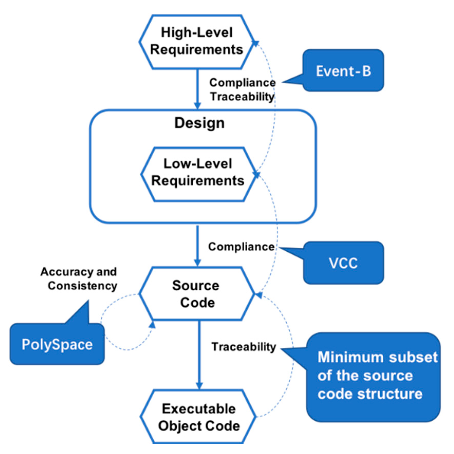
The primary verification process for this case is shown in
Figure 4. Since the ADC software contains many modules, the functions of the entire software are considered first during the requirements design phase, and different functions are detailed in the specific module. Therefore, refinement strategies can be considered in verification at the requirements level. This is why we chose to use Event-B, which is based on model refinement to verify the relationship between HLR and LLR, as shown in
Section 4.1. In terms of traceability between source code and requirements, we need to individually verify whether the code of each module in ADC can realize the requirements. Therefore, we consider the VCC tool, which can separate each module independently and achieve separate requirements verification objectives without requiring a full scan of the entire software code. The relevant content is described in
Section 4.2. In
Section 4.3, PolySpace is used to detect the source code statically, because it is a relatively mature tool for static analysis of codes, which can detect runtime errors without running programs in the actual environment. Finally, we verify the traceability between the EOC and the source code by analyzing the minimum subset of the source code structure (
Section 4.4). The detailed verification process will be described below.
4.1. Compliance and Traceability from Low- to High-Level Requirements
To verify the relationship between HLR and LLR, a refinement strategy is considered. The modeling process commences from an abstract model and attains the final form of an efficient system through continuous refinement, which ensures traceability between the LLR and HLR. Event-B is a modeling language based on refinement strategy, which allows controlling of the complexity of a system with progressive and safe development. Rodin is the application platform for Event-B language. Its crucial functions include modeling, static syntax analysis, model verification, etc. Rodin can automatically generate proof obligations, and integrate SMT solvers (such as Z3, CVC3) and theorem prover (Isabella) for automatic or interactive verification for validity of the generated proof obligation [
55]. The accuracy of the refinement can be guaranteed by verifying the proof obligation in the model.
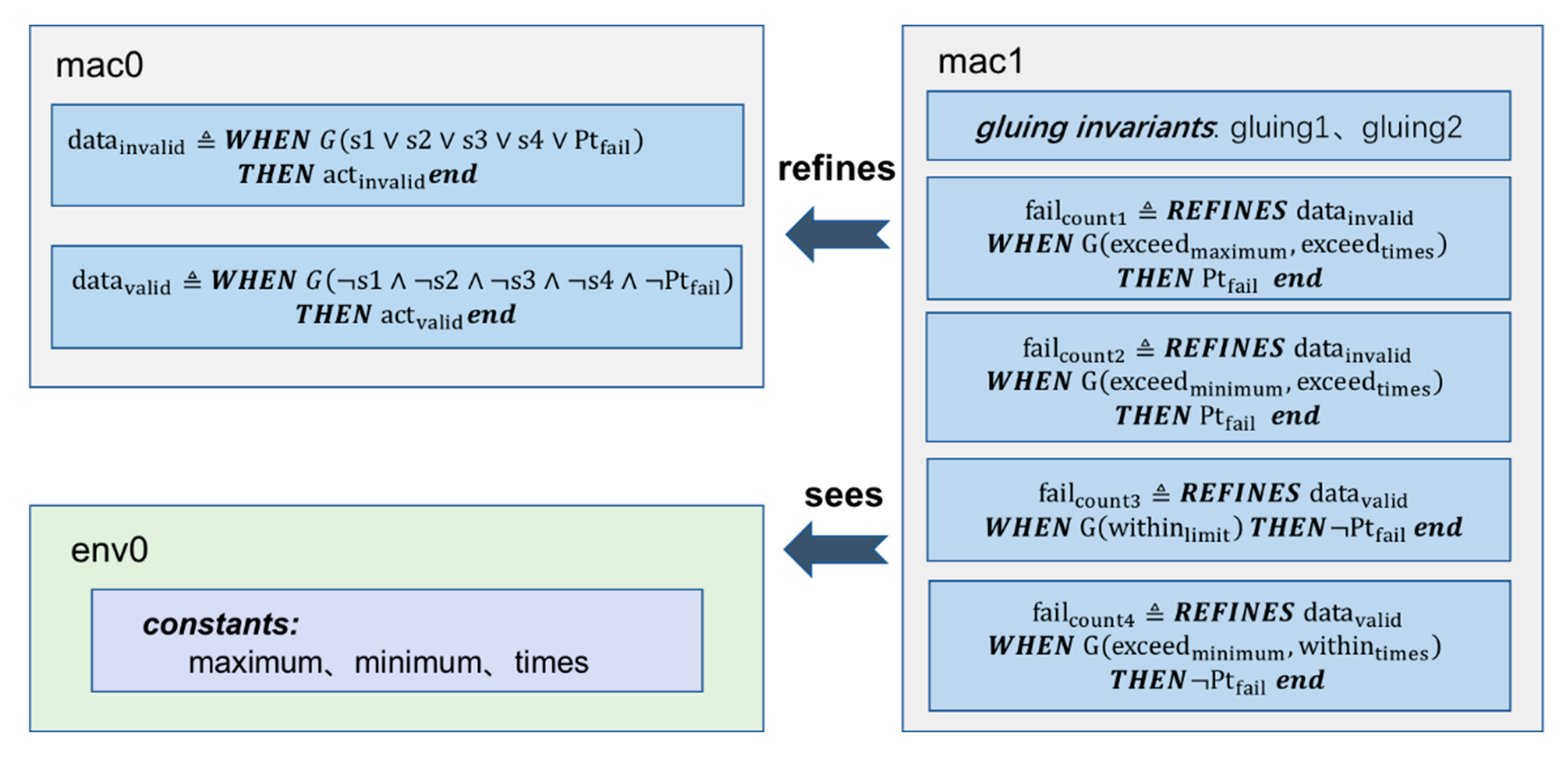
Figure 5 is the Event-B model based on requirement specifications and behavior descriptions of the parameter validity module.
In mac1, we refined the state value of Ptfail, which was a Boolean variable, and counted the number of times the total pressure value exceeded the boundary. If the total pressure value exceeded the limit and reached 10 consecutive times, Ptfail was set to be true; otherwise, its value was false. At the same time, we used two gluing invariables in mac1 to describe the conversional relationship of Ptfail between the two machines.
After the model was built, Rodin generated proof obligations, for example: failcount1/actinvalid/SIM. SIM means “simulation proof obligation”, its purpose is to make sure that each action in an abstract event is correctly simulated in the corresponding refinement. Another example is failcount1/gluing1/INV. INV means “invariant preservation proof obligation”; it ensures that each invariant in a machine is preserved by each event. Some of Rodin’s built-in theorem provers can automatically verify most of the proof obligations. For the remaining obligations, we manually add certain qualifications to show the satisfaction of these invalidated rules or prove them interactively by using the integrated provers with inductive rules. Verification of all the proof obligation rules can ensure correctness of the model, as well as consistency between HLR and LLR.
In this case, we established the original model according to the requirements document and the refined model using the detailed design document; we found that certain SIM obligations could not be automatically verified. After exploring the reasons, it was found that some data outside the boundary values were not further processed in the detailed design. After we had identified a further refinement of the requirements, we added the qualification conditions in the refined model and made a corresponding supplementary operation. All of the proof obligations were then verified.
Since LLR was refined from HLR, we were able to achieve verification goals in DO-178C Appendix A [
5], including:
Table FM. A-4, Objective FM1: Low-level requirements comply with high-level requirements.
Table FM. A-4, Objective FM6: Low-level requirements are traceable to high-level requirements.
At the same time, we formalized the requirements in mathematics based on natural language, which gets rid of ambiguity and integrates them to be dispersed in different chapters, without any interference and consideration from the real code. This process can also verify the accuracy, consistency, and verifiability of requirements (Table FM. A-3: Objective FM2, FM4; Table FM. A-4: Objective FM2, FM4, etc.).
4.2. Compliance from Source Code to Requirements
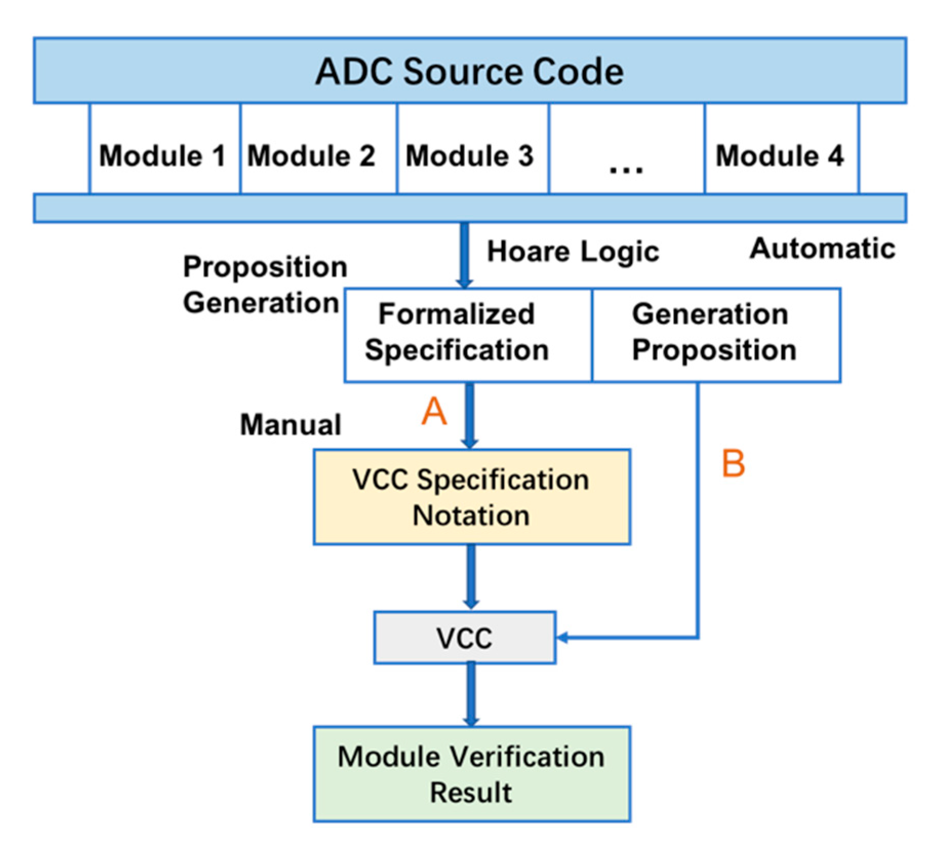
The ADC software is implemented in C code. To realize automatic verification in C code, we applied Verifying C Compiler (VCC), a tool developed by Microsoft Research, to guarantee compliance from source code to requirements. VCC is based on a Satisfiability Modulo Theories (SMT) solver called Z3 [
56]. It uses the patterns of deductive proof to generate a certain number of validity specifications. By using VCC, we first formalized the specification by Hoare Logic and manually transformed the pre- and post-conditions into annotations that can be accepted by VCC. VCC generates a logic language (Boogie PL) program through the annotated C program, and then generates a standard input of theorem provers such as Z3 for verification. All of the specifications and other required information should be manually added as annotations to the source code, which may require some expertise; following this, VCC will automatically verify the code. The verification process is shown in
Figure 6.
If the proof is successful, VCC will assume that the program meets the specifications. If the proof fails, VCC will reflect on the reason for failure. VCC sometimes reports some (potential) errors because we do not provide enough information to let VCC infer that this suspected error may not occur. Usually, this “error” can be solved by strengthening the annotations.
The following is a sample of the annotations for validity of total pressure parameters. Detailed grammar rules are found in [
57]. The full version of the formal specification of the module contains formalizations of 15 parameters—about 72 properties—and cost approximately two man-weeks. After the verification, we found an (potential) error: the specification on checking the rationality of some data cannot be satisfied by the program.

The verification objective can be achieved by reviewing and resolving the error: Table FM. A-5, Objective FM1: Source code complies with low-level requirements.
4.3. Static Analysis of Source Code Level
The static analysis technique can be used to detect and prove run-time errors in source code. PolySpace is a static analysis tool that focuses on the embedded systems market, involving safety or life-critical applications, which is suitable for airborne software. In this case, we chose the PolySpace Code Prover to statically analyze the source code. It can prove the absence of overflow, divide-by-zero, out-of- bounds array access, and other run-time errors in C and C++ source code [
58].
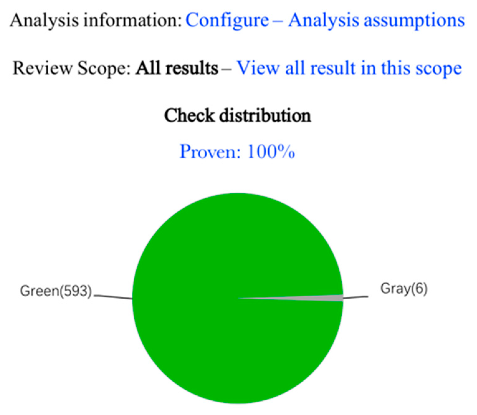
We created a new project in PolySpace, placed the code together with its associated headers in the same folder, and then ran the code prover. After the operation, each code statement was color-coded to indicate whether it is free of run-time errors, proven to fail, unreachable, or unproven. The analysis results of the parameter validity module are displayed in
Figure 7. As can be seen in the figure, there are some unreachable codes (dead code). On clicking on the section we are focusing on, the program jumps to the relevant code area. A manual review observed that certain logic errors result in a dead code. Some program blocks can never be executed because the corresponding conditions will never be satisfied.
By solving the problems found by PolySpace, we can achieve the following verification objectives:
Table FM. A-5, Objective FM3: Source Code is verifiable.
Table FM. A-5, Objective FM6: Source Code is accurate and consistent.
4.4. Traceability from Executable Object Code to Source Code
As explained in RTCA/DO-178C, airborne software structure coverage analysis can be performed at the source code level. If the software is at the A level and the object code generated during the compilation cannot be traced back to the source code, additional validation must be performed at the object code level to ensure correctness of the object code [
59]. Hence, for the object code generated by the A-level airborne software, in addition to source code level coverage analysis, the traceability analysis between the source code and the object code must be completed, and the additional object code that cannot be traced back to the source code should be further verified. The methods mentioned in
Section 3.3 will be applied to verify traceability from EOC to source code so that the verification objectives of the EOC can be achieved.
In general, traceability from EOC to source code can be performed using two strategies: comprehensive object code analysis and minimum subset of source code structure analysis. Comprehensive object code analysis compiles the source code into assembly code, and thereafter manually determines which object code is not required to run the source code. The main purpose of analyzing the minimum subset of the source code structure is to write the sample code according to the constraints of the software coding standard, compile it, and use manual analysis to examine the trace relationship between the object code of the sample code and the source code [
60]. In comparison to comprehensive code analysis, the work for traceability analysis of the source code structure minimum subset analysis method is greatly reduced, and the analysis report can be reused in multiple onboard software projects [
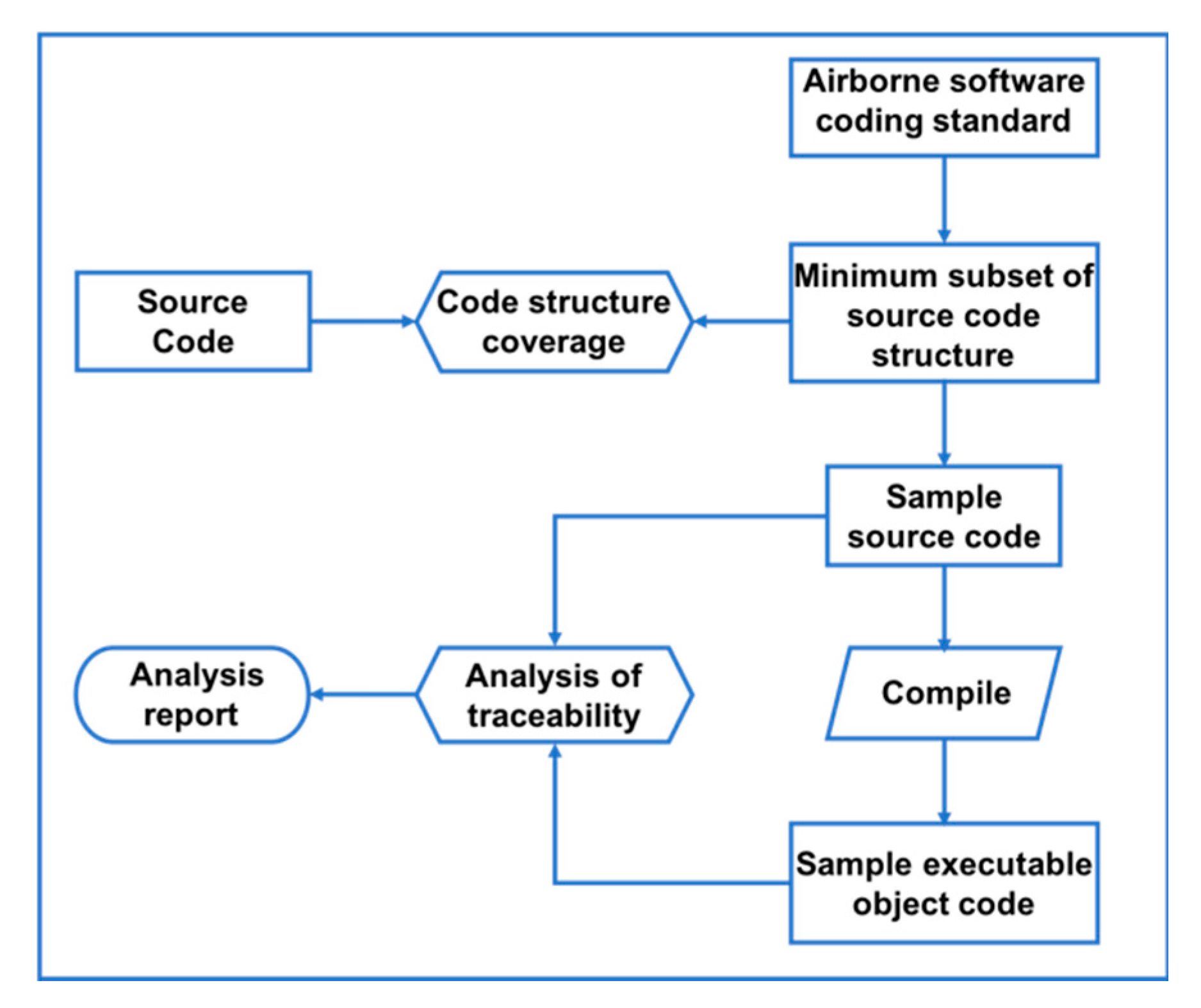
61]. To demonstrate the versatility of this method, minimum subset of code structure analysis was applied to verify the traceability from EOC to source code, based on three aspects (discussed below). The method is displayed in
Figure 8.
1. Traceability from sample object code to sample source code: According to ADC software coding standards, the programming language, rules, complexity, etc. used in software coding are first constrained and limited; thereafter, the minimum subset of software source code structures is extracted as per the constraints and restrictions in the ADC software coding standard. This is followed by comparison of the source code of the ADC software project with the minimum subset of the source code structure; this helps determine whether the minimum subset of the source code structure covers all source code structures in the ADC software project. Subsequently, the sample source code is compiled, according to the minimum subset of the source code structure. The sample source code is actually compiled in the same compilation environment, which includes the use of the same compiler and setting of the same options to compile the sample code. This is followed by manual analysis of traceability from sample EOC to sample source code.
2. Consistency from sample object code to ADC software object code: On comparing the sample object code and the ADC software object code through manual analysis, we verify that the ADC software structure coverage meets the requirements of RTCA/DO-178C at the object code level.
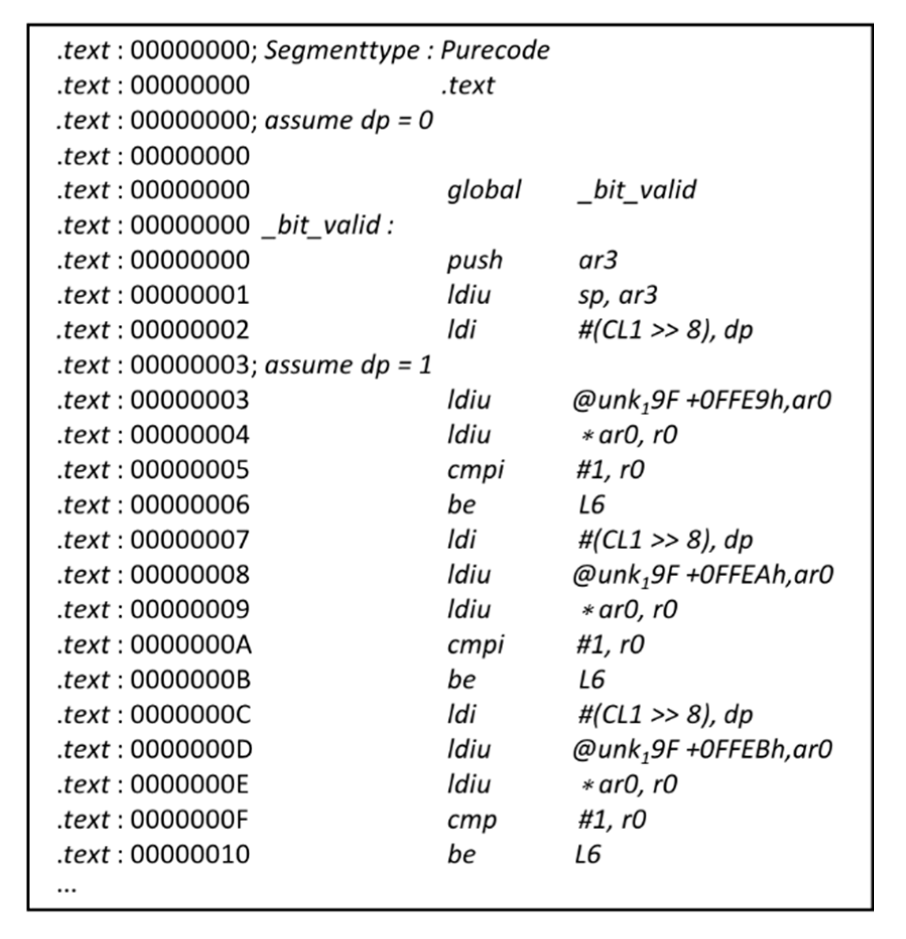
3. Consistency from sample source code to source code decompiled by ADC software object code: Based on the existing object code of ADC software, the IDA Pro was utilized in this project as a disassembly tool. The assembly instructions acquired by IDA Pro was shown in
Figure 9. As mentioned previously, it is a powerful and complicated tool, as it consists of several plugins. The Hex-Rays Decompiler, which is one of its well-known plug-ins for automatic decompilation, was used to decompile the assembly instructions into C files. More importantly, it supports the compiler-generated code for the x86, x64, ARM32, ARM64 and PowerPC processors, satisfying the needs of most airborne software decompilations [
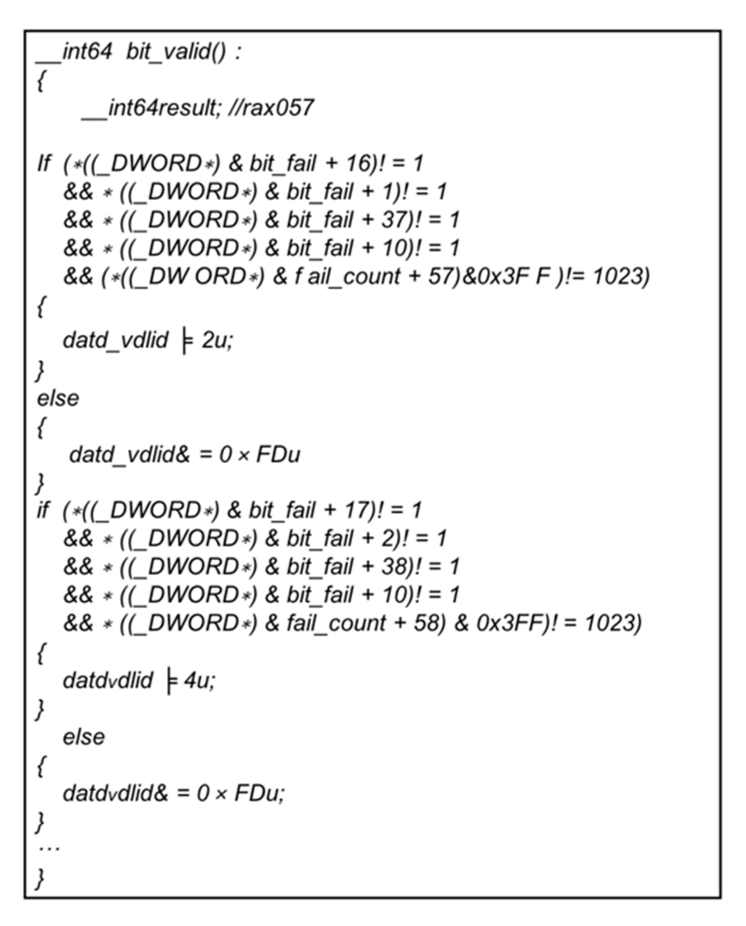
62]. The Hex-Rays Decompiler was used to decompile the object code of the ADC software to acquire the decompiled source code, as displayed in
Figure 10. By manually analyzing the sample source code and the generated source code decompiled from the ADC software object code, not only can the object code that cannot be traced back to the source code be identified, but it can also confirm that the additional object code is correct by combining the first aspect.
By verifying the traceability of the target code to the source code, the objective can be guaranteed.
Then, the properties of the executable object code can be speculated by analyzing the source code.
4.5. Analysis of the Verification Results
In this paper, we introduced the verification properties and results of the ADC software’s parameter validity module at each step, and analyzed the errors found by formal verification. In
Table 2, we summarize the issues observed in the case study of the ADC software.
The ADC software has a total of 12 modules. Formal verification of each module was conducted separately, as per the process mentioned above. The verification process was divided into four stages: formal analysis of requirements and design, compliance from source code to requirements, static analysis in source code level, and formal analysis of the executable object code. The properties under verification refer to the properties that the artifacts produced at each stage need to be satisfying. The total number of the verified properties in ADC software was 1049. After the formal verification process, we found some unsatisfied properties at various stages, known as potential errors. These errors had to be reviewed and analyzed again as the formal tools used in the verification process were not qualified. After a manual review, some potential errors were eliminated, and the rest identified as errors. Through modeling in Event-B, certain inconsistencies were observed in the abstract and the refined model, which indicated logic problems in the requirement and design documents. Some potential errors detected by VCC were determined to be caused by not qualifying the conditions of the annotations. Hence, the actual number of errors was less than the potential errors. For static analysis in the source code level, PolySpace detected some potential errors such as bad return value, uninitialized variables, dead code, etc. After retesting, it was observed that certain potential errors would never occur. The reason for such phenomenon is that static analysis usually adopts an abstract model of the program, which can result in the loss of some information, thereby producing false alarms. During verification of the binary code, we found that some additional generated object codes could not be traced back to the source code. By validating the additional generated object codes through manual review and analysis, we found that they were generated automatically for functions such as handling exceptions and checking the boundaries of the array. In the last column of
Table 2, the time spent on each phase of the project is displayed.
The ADC software was tested prior to formal verification. It can be seen in
Table 2 that formal verification can detect certain errors that testing cannot find, especially for products that are in the early stages of development, such as requirement and design documentation. This shows that formal verification can identify errors much earlier in the design cycle, as compared to testing, which potentially saves money, due to less scrap and rework. Besides, static analysis can detect errors, which, in practice cannot be identified by testing, like dead codes. However, formal verification is time-consuming, incurs high costs, and requires the verifier to be highly skilled. Therefore, the application of formal methods is highly recommended as a supplement to testing and to identify problems that testing alone cannot resolve.
The verification objectives implemented in this case are summarized in
Figure 11.
- • indicate that verification objective is fully satisfied.
- ◦ indicate that verification objective is partially satisfied.
Some verification objectives are partially satisfied, indicating that only a portion of the properties required by the objectives can be verified. For example, the objective of high-level requirements conforming to standards that can only be partially proved; in this project, only the Event-B model that describes the high-level requirements conforms to the syntax standards of Event-B. Due to the two-way tracking relationship of traceability, traceability from source code to low-level requirements verified by VCC can only show that all low-level requirements are developed into source code, but it cannot be inferred that all source code can be traced to some low-level requirements, which can be illustrated through a review.
DO-178C states that the tools used to generate software or to verify software must be verified to ensure degree of accuracy. This process of verifying the accuracy of tools is known as qualification. Since the tools applied in this case can automate the verification process and their outputs used to justify the elimination of or reduction in verification processes, these tools must be qualified, as these processes may fail to detect errors. The specific tool qualification process should refer to the DO-330 (Software Tool Qualification Considerations) issued by the RTCA. The verification results can also be double-checked through review techniques and other analysis methods. In the software life cycle, reviewing methods such as planning, requirements, design, code, and peer reviews can be used to review software products in different development periods. Analysis methods include functional hazard assessment (FHA), failure modes and effects analysis (FMEA), failure tree analysis (FTA), common cause analysis (CCA), etc. A double-check refers to verification using another method for objectives that have not been verified. For example, in the verification of traceability of object code, if the object code produces a redundant code, then the impact of this part of the code must be explained through analysis. In addition, simulation and testing are common software verification methods.
This example shows in detail how to select an appropriate formal method based on the level and characteristics of the software. During the verification process, we divided the activity into three stages and selected different formal methods for each stage. The selection of specific verification tools is based on the characteristics of the software and the verification objectives to be realized. For example, in the requirements stage, in order to verify the compliance and traceability between HLR and LLR, we considered the Event-B model based on refinement strategy, which can ensure transitivity between the two layers’ models through the built-in prover of the Rodin platform. In actual industrial applications, we need to refer to the verification objectives of different levels of airborne software defined in tables FM. A-3 to FM. A-7 in DO-333 to consider the formal verification methods to be used. Due to the cost and difficulty of formal verification, review and analysis remain the primary means of airborne software verification. On this basis, for some verification objectives that are difficult to achieve through review and analysis methods, appropriate formal methods should be selected for verification based on the characteristics of the software.
5. Conclusion and Future Work
Based on research on DO-333, this paper proposes a methodology to apply formal methods to the development and verification processes of airborne software. The methodology described in this paper covers the entire verification process of A-level software, as stipulated in DO-333. In this paper, the ADC software was cited to illustrate how the recommended methodology can be practically applied. A reference has been provided for the software verification process, which applies several formal verification tools mentioned in the methodology at different stages of the verification process to achieve multiple objectives. As is evident from the examples, formal methods can be applied to various stages of the software development process to identify certain errors at an early stage. Correcting these errors can reduce the cost of testing and reworking. In addition, it is not difficult to infer that formal methods are particularly convincing as they provide strong guarantees based on rigorous mathematical theories. It is hoped that readers of this paper are inspired by this example to practically apply formal methods.
This paper successfully demonstrated the role of formal methods in the airworthiness certification process of airborne software. We are convinced that techniques, methods, and tools combining formal verification are the future of system verification. It can be safely assumed that in the near future, as more theories and tools become available for avionics, more formal verification techniques will be applied. These techniques are an effective approach to address the dramatic increase in issues arising from complexity of software, especially when safety is at stake. However, the abstraction and complexity of formal development methods make it difficult for non-professionals to comprehend and apply these methods effectively. It is very likely that substantial efforts and capital will be expended on the analysis of requirement modeling, software design, verification, and qualified tools. Therefore, we have decided to utilize a qualified toolchain for formal verification of airborne software in our next research endeavor. We are still working on advancing the application of formal methods on airborne software based on DO-333.


