Abstract
Field programmable gate arrays (FPGAs) are increasingly used in industry (e.g., biomedical, space, and automotive industries). FPGAs are subjected to single, as well as multiple event upsets (SEUs and MEUs), due to the continuous shrinking of transistor dimensions. These upsets inevitably decrease system lifetime. Fault-tolerant techniques are often used to mitigate these problems. In this research, penta and hexa modular redundancy, as well as dynamic partial reconfiguration (DPR), are used to increase system reliability. We show, depending on the relative rates of the SEUs and MEUs, that penta modular redundancy has a higher reliability than hexa modular redundancy, which is a counter-intuitive result in some cases since increasing redundancy is expected to increase reliability. Focusing on penta modular redundancy, an error detection and recovery mechanism (voter) is designed. This mechanism uses the internal configuration access port (ICAP) and its associated controller, as well as DPR to mitigate SEUs and MEUs. Then, it is implemented on Xilinx Vivado tools targeting the Kintex7 7k410tfbg676 device. Finally, we show how to render this design fault secure in the event that SEUs or MEUs affect the voter itself. This fault secure voter either produces the correct output or gives an indication that the output is incorrect.
1. Introduction
The automotive industry is one of the largest global markets in the world. It has a lot of electronic systems to meet driver requirements. Vehicles merge between engine control units (ECUs) and other systems to control many functions such as airbags, tire pressure, the antilock braking system, infotainment, body electronics, CAN/LIN bus controllers, lighting systems, and advanced driver assistant systems (ADAS) [1]. Embedded processors are well suited for many of these systems. Because field programmable gate arrays (FPGAs) have high speed and large logic densities, FPGAs facilitate the development of vehicle infotainment and communication [2]. FPGAs are the best candidates for some applications such as automotive, space, and biomedical applications [1,2,3].
FPGAs provide the capability of being reprogrammed to execute different functions. They have high performance via implementing an algorithm in an efficient way. They simplify the task of adding new features to the product as compared with ASIC-based embedded systems.
There are different families of FPGAs, i.e., SRAM, Flash/EPROM, and Antifuse [4]. The majority of FPGA families are SRAM-based FPGAs. SRAM-based FPGAs are susceptible to atmospheric radiation as some neutrons can interact with a silicon nucleus and create alpha particles which cause bit flipping induced hardware alterations. This is called a single event upset (SEU).
Nowadays, in new technologies under 130 nm [3], transistors are continuously shrinking. Hence, it may be possible for one single particle to interact with more than one cell and induce multiple event upsets (MEUs). When incident particles hit die contaminants, secondary particles with enough energy are generated to create multiple event upsets (MEUs). There is a probability of adjacent and non-adjacent MEUs depending on the incident angle, the die contaminant type, and the scattering angle of secondary particles [5]. User constraints can be used to control the floor planning of the design modules during the design implementation on FPGAs [6]. According to this feature, designed modules can be spatially mapped away from each other to mitigate adjacent MEUs. This approach can mitigate adjacent MEUs but cannot guarantee the mitigation of non-adjacent MEUs which might occur due to secondary particles.
In [7], many fault tolerance techniques were studied to mitigate SEUs and MEUs (especially non-adjacent double event upsets (DEUs)). The first technique is scrubbing; it requires a time interval (this time interval can be in order of milliseconds) between the occurrence of the error in the configuration memory of the FPGA and the time to discover and repair this error [8]. The second technique is triple modular redundancy (TMR), which is a famous fault tolerance technique but it has a problem with detecting and correcting non-adjacent double event upsets (DEUs) that affect two modules, thereby producing a system failure. Finally, the last two techniques are penta modular redundancy (5MR) and hexa modular redundancy (6MR); they can recover from SEUs and MEUs accurately but 6MR can detect more sequences of failures than 5MR.
In this research, we show, for the first time, that adding redundancy may not necessarily increase system reliability, which is a counter-intuitive result in some cases. The consensus in the literature is that more redundancy leads to an increase in reliability. This justifies the extra cost. To the best of our knowledge, this is the first time an increase in redundancy is shown to lead to a decrease in reliability. Depending on the relative frequency of occurrence of SEUs and MEUs, 5MR may be more reliable (and obviously less expensive) than 6MR.
The second contribution of this paper focuses on 5MR, an error detection and recovery mechanism that is designed from scratch and implemented on Xilinx Vivado tools targeting the Kintex7 7k410tfbg676 device. Simulations prove that it performs correctly. As the fault model used in this research focuses on transient faults, the proposed design has the capability of applying dynamic partial reconfiguration (DPR) to recover from soft errors.
Finally, the proposed design of the error detection and recovery mechanism is further modified to add the property of fault security [9,10,11]. Since the mechanism is implemented on the FPGA, it is also susceptible to SEUs and MEUs. In the case of an error affecting the mechanism itself, fault security guarantees that it produces the correct output or gives an indication that the output is incorrect. Using erroneous outputs can lead to disastrous consequences. A fault secure error detection and recovery mechanism gives an error indication right away and downtime is limited to the replacement of an FPGA.
This paper is organized as follows: In Section 2, we introduce related work and discuss the effect of failure rates on reliability calculations for 5MR and 6MR, and then Markov models are used to carry out these calculations; in Section 2, we also present the design of the penta modular redundancy (5MR) error detection and recovery mechanism as well as the design of a fault secure 5MR error detection and recovery mechanism; in Section 3, we present the reliability results based on different failure rate ratios and implementation results for the proposed penta modular redundancy (5MR) design; in Section 4, we discuss the results; and finally, in Section 5, we conclude this paper.
2. Materials and Methods
The combination of reconfiguration, low cost, and flexibility has led to the use of FPGAs in the automotive industry [1,2]. FPGAs are susceptible to radiations causing SEUs and MEUs. There are many fault-tolerant techniques to recover from FPGA upsets. Some of these techniques can be used to mitigate SEUs, such as scrubbing and TMR. However, penta and hexa redundancy techniques can be used to mitigate both SEUs and MEUs (DEUs).
Scrubbing is the most commonly technique used for mitigating upsets in FPGA. The major problem with scrubbing is the detection time; there is a certain amount of time between the occurrence of an error in the configuration memory and discovering it then repairing it. This time interval can be in the order of milliseconds before the correct state of the configuration memory (CRAM) bits is restored [8]. The system may produce an erroneous result, during this time interval, and this is not acceptable in safety critical modules in automotive systems; therefore, scrubbing cannot be used to recover from SEUs or MEUs.
Triple modular redundancy (TMR) is also a potential solution to mitigate upsets in FPGA. The targeted module (M) is triplicated, and a majority voter circuit produces the correct output. Dynamic partial reconfiguration (DPR) can be used to recover the failed module. TMR produces an incorrect output if the majority voter circuit fails, i.e., the detection time interval is not a problem with TMR. Hence, TMR can only detect and correct a single module failure at a time. The problem with TMR is the occurrence of non-adjacent double event upsets (DEUs) affecting two modules, which produces a system failure. TMR solves DEU problems if they occur in the same module but produces an erroneous output when two memory cells of two modules are simultaneously affected [10,12].
The shortcoming of TMR can be solved using penta modular redundancy (5MR), which can mitigate SEUs, as well as DEUs [13,14] and follows the same methodology as that of TMR. Five identical copies of the module (M) are connected to an error detection and recovery mechanism. The failed modules can be recovered using DPR if the problem is transient. 5MR can tolerate 3 successive single failures in 3 different modules (Ms) or a double failure in two Ms followed by a single failure in a third M but the sequence of a single module failure followed by a double failure cannot be mitigated by 5MR.
The hexa modular redundancy (6MR) fault-tolerant technique [7,10] can detect this specific sequence, as well as additional failure sequences. 6MR follows the same methodology as TMR and 5MR. Six identical copies of the module (M) are connected to an error detection and recovery mechanism. 6MR can tolerate 4 module failures as follows: (1) 4 successive single failures in 4 different Ms, (2) a single failure followed by a double failure followed by another single failure, and (3) a double failure followed by 2 successive single failures. These failure sequences of 6MR are explained in Figure 1. The failed modules can be recovered using DPR.
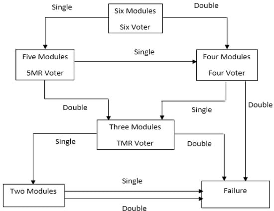
Figure 1.
Hexa modular redundancy (6MR) flow chart.
In [7], it was proven that 6MR was more reliable than 5MR, with λs (SEU rate) 10 times higher than λd (DEU rate) based on the data in [3,15]. The reliability was calculated by simulating Markov models for 5MR and 6MR using SHARPE [16]. Five identical copies of a 32-bit embedded MicroBlaze soft core processor (widely used in automotive electronic systems) have been implemented for the 5MR system and six identical copies for the 6MR system. The effect of different ratios between λs and λd on reliability are studied in the next section.
2.1. Effect of Failure Rates Ratio on Reliability
In this subsection, the reliability was studied for the 5MR and 6MR fault tolerance techniques using different ratios between λs and λd as the ratio may be 10 or less [17,18]. Figure 2 and Figure 3 show Markov models for 5MR and 6MR [10,19].
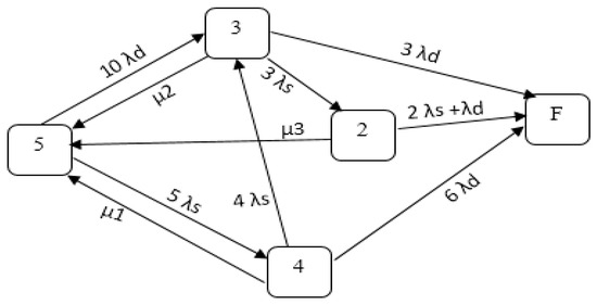
Figure 2.
Penta modular redundancy (5MR) Markov model.
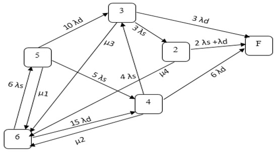
Figure 3.
6MR Markov model.
As mentioned in this section, for the 5MR system, five identical copies of the module (M) are connected to a voter (an error detection and recovery mechanism). 5MR can tolerate 3 successive single failures in 3 different Ms or a double failure in two Ms followed by a single failure in a third M. DPR is used to recover the failed modules [7]. For the Markov model in Figure 2, the state is named according to the number of operating modules in this state and “F” is the failure state. Let λs be the rate of SEUs affecting any module M and λd be the rate of DEUs affecting two modules. The model has different repair rates (µ1, µ2, µ3, and µ4) because the repair time depends on the amount of time taken to complete the DPR and this time depends on the size of the bit file (=1/µ1). Therefore, in state “5”, only one M has to be reconfigured while, in state “4”, two Ms have to be reconfigured (µ2 = 0.5 µ1 and µ3 = 0.333 µ1) [7]. Failures and repair times are both assumed to be exponentially distributed; hence, the repair rate µ and the failure rate λ are constant [10].
Reliability (R(t)) is the probability that a system is alive at time t given that it was alive at t = 0 [10]. Reliability is the probability of NOT being in state “F” at any time t as follows:
where is the system reliability and is the probability of the system being in state F (failure state).
The 5MR Markov models can be solved using the Chapman–Kolmogorov equations [10]. Let be the probability of residing in state at time as:
where is the transition rate matrix, and
Then,
and,
Therefore, assuming that , , and using the transition rate matrix in Equation (3) and substituting in Equation (2), the Chapman–Kolmogorov equations can be solved in order to obtain . Then, Equation (1) is used to obtain .
6MR follows the same methodology as 5MR. Six identical copies of the module (M) are connected to a voter (an error detection and recovery mechanism). 6MR can tolerate 4 module failures as follows: (1) 4 successive single failures in 4 different Ms, (2) a single failure followed by a double failure followed by another single failure, (3) a double failure followed by 2 successive single failures. The Markov model in Figure 3 can be explained and solved using the same reasoning as the 5MR model in Figure 2 [7].
2.2. Penta Modular Redundancy (5MR) Implementation
In this subsection, we discuss the penta modular redundancy (5MR) voter implementation. The 5MR voter is implemented in addition to its modules (Mi) on the same FPGA, as shown in Figure 4.
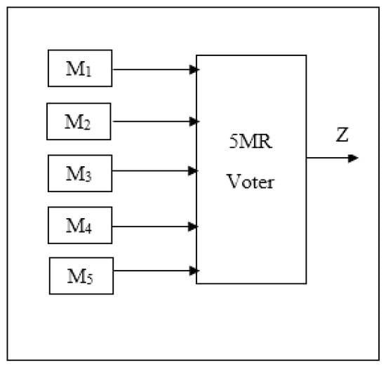
Figure 4.
Penta modular redundancy-based field programmable gate arrays (FPGA).
Proposed Design
The 5MR reconfiguration scheme is shown in Figure 5. Next, is a very brief description of the functionality of each of the three blocks V, W, and MAJ. Block V compares each of the module outputs to the voter output using an XOR gate, as shown in Figure 6. When the module fails, the XOR produces a logic 1 which is, then, stored in a D flip-flop (with output qi) to indicate that this module has to be removed from the voting process. The outputs of the 5 XOR gates (DPR1 through DPR5) are also sent to another module, as will be explained later. Each D flip-flop has a separate reset signal ri.
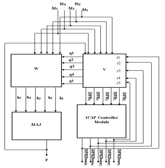
Figure 5.
The 5MR reconfiguration scheme.
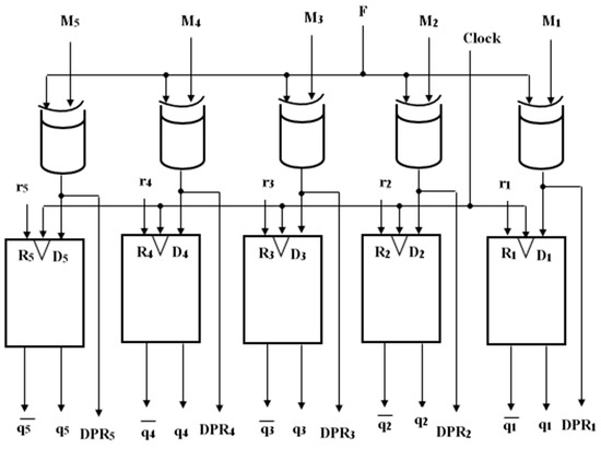
Figure 6.
Logic diagram of Block V.
Block W has two sets of inputs, i.e., the outputs of the 5 modules (M1 through M5) and the outputs of the 5 flip-flops (q1 through q5) in Block V. Block W consists of five sub-blocks; one of these sub-blocks is shown in Figure 7. In the error-free case, Block W produces the outputs of the five modules, i.e., Mi = hi in Figure 5. When one module fails, its corresponding h output becomes a logic 0 while the output h of another module becomes a logic 1. Block MAJ being a 5-input majority voter and two of its inputs being constant at 0 and 1, it functions as a 3-input majority voter (as in triple modular redundancy (TMR)). If two modules fail simultaneously, one of their corresponding h outputs becomes a logic 0, while the other becomes a logic 1. Again, Block MAJ becomes a 3-input majority voter. All D flip-flops are reset at the beginning of operation. All D flip-flops have the same clock. If DPRi = 1, then qi is set (qi = 1) when the clock pulse occurs. If all modules are fault free, then qi = 0 for all D flip-flops. It is worth noting that the design of Block W is identical to the one in [20].
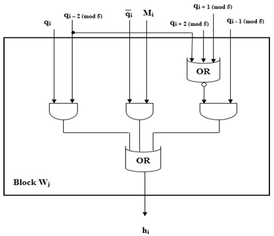
Figure 7.
Logic diagram of Block Wj.
Since the fault model in this research includes SEUs and MEUs (transient faults), it is important to use DPR to attempt to repair a failed module instead of removing it from the voting process, especially since the frequency of occurrence of transient faults is much higher than that of permanent faults [21].
Block V is designed to consider DPR, as shown in Figure 6. The outputs of the XOR gates (DPR1 through DPR5) are to be used by another module below. DPRi = 1 if the Mi has a fault (Mi has a different value from the system output F).
Another important part of the voter design is the use of the internal configuration access port (ICAP) and its associated controller [22]; ICAP has direct access to the FPGA configuration memory. ICAP is a primitive used for DPR. Figure 8 shows how the ICAP interacts with the voter to take DPR into account. As soon as DPRi = 1, the D flip-flop associated with module Mi is set and Mi is not considered in the voting process. While the system is still operating with the remaining four fault-free modules, the ICAP performs DPR on Mi and monitors DPRi. If DPRi returns to “0”, the fault must have been transient and the ICAP resets the D flip-flop associated with Mi (using the separate reset signal r, as mentioned above). Each module has an ICAP status bit (status flip-flopi) associated with it (see Figure 8) and controlled by the ICAP module. Let this status bit be called DPRDonei. This status bit is initially reset indicating that its associated module is fault free or that DPR was performed on this module and was able to recover from the transient fault. If DPR does not succeed in repairing Mi, the ICAP writes a “1” in the corresponding status bit. Consequently, Mi is considered to have an irrecoverable fault and is permanently removed from the list of modules on which the ICAP can still perform DPR.
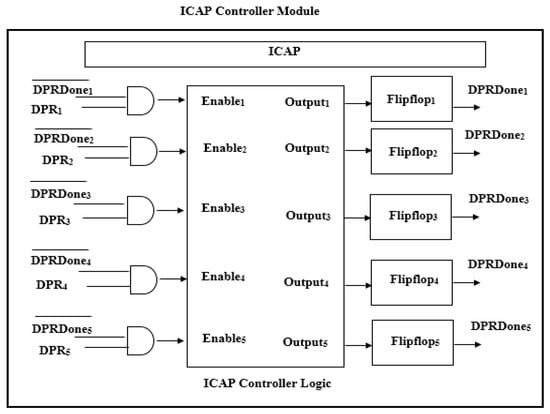
Figure 8.
Internal configuration access port (ICAP) controller module.
The enable signal (Enablei) is equal to”1” if the ith module failed (DPRi = 1) and (DPRDonei = 0). Remember that the signal “DPRDonei = 0” is an indication that DPR has already been applied to Mi and that it was successful, or the module Mi has never suffered from any upsets. DPRDonei is connected to the reset signal corresponding to this module (ri).
2.3. Fault Secure Voter Design
The area occupied by the voting circuitry is much smaller than that occupied by the five modules. Hence, the reliability of the voter is expected to be much higher than that of any of the five modules. However, it may still be affected by SEUs or DEUs. This will cause the voter to produce an incorrect output and the rest of the system will have no indication that the signal received is incorrect. Next, we show how to solve this problem using the concept of fault secure circuits [9,10].
A circuit is fault secure if, for every fault from a prescribed set, the circuit never produces an incorrect codeword output for codeword inputs [9]. Let “A” be the set of all input vectors applied to the voter system. There are 32 (=25) input vectors in this set (as long as at least two of the five identical modules are functioning). Let “a” be any vector in “A”.
The fault set considered for the voter is the same as that considered for the five modules, namely SEUs and DEUs. Therefore, let “B” be the set of all faults considered in this research, namely SEUs and DEUs in the voter system and “b” any member of this set. In addition, let φ be the null fault, i.e., the circuit is fault free.
The voter is triplicated, as shown in Figure 9. Its output consists of a three-bit vector. Let OUT(a,φ) be the three-bit vector produced by the three voters in the fault free situation, OUT(a,b) the output of the three voters in the presence of any fault b (Ɛ of B). Only two of the eight possible combinations constitute valid codeword outputs, i.e., 000 and 111. The reason for triplicating the voter circuitry instead of just duplicating it is the effect of DEUs, even if the three copies of the voter are not physically adjacent. Floor planning of the design voters can be controlled during the design implementation on FPGA via user constraints [6]. Therefore, designed voters can be spatially mapped away from each other to mitigate adjacent MEUs but this feature cannot guarantee the mitigation of non-adjacent MEUs. Two of the three copies may be affected by one DEU. If the voter had been duplicated instead of triplicated, there would not have been any indication that the output was incorrect; a correct 00 codeword could be changed by the DEU to another correct codeword, namely 11.
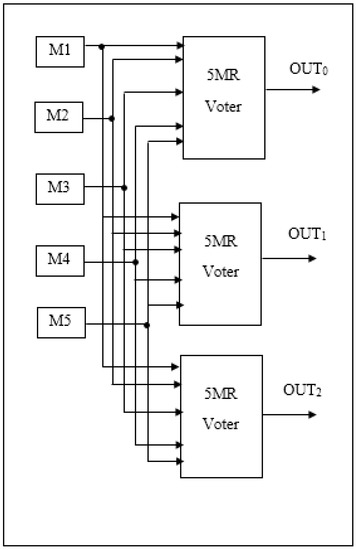
Figure 9.
Fault secure design-based FPGA.
The three-voter system is fault secure as follows:
- OUT(a,φ) Ɛ C
- OUT(a,b) Ɛ C → OUT(a,b) = OUT(a,φ)
The disadvantage of the proposed scheme is that any module receiving the output of the voter has to “decode” this voter output.
3. Results
3.1. Reliability Results
The presented Markov models for 5MR and 6MR are simulated using SHARPE [16] to calculate the reliability. Machine learning and deep learning have many applications in the automotive field, inside and outside the vehicle [23]. The module (Mi) used in this research is the Alexnet accelerator (an important module in machine learning and neural networks [24]). Let the module SEU rate λs = 0.012/h based on the data in [24,25]. According to the data in [18], λs is approximately twice λd (DEU rate). Remember that in [7], the ratio used was λs = 10 λd; this ratio was based on the data in [3,15]. Obviously, this ratio can differ based on the environment in which the system is operating. Therefore, next, several ratios are simulated (λs = 3 λd and λs = 5 λd) to investigate the effect of the ratio on system reliability. In addition, let the repair rate of one module M be μ1 be around 144/hour (where 1/μ1 is the average time to download 1 bit file corresponding to the Alexnet accelerator neural network [24,26]), μ2 = 1/2 μ1 since 1/μ2 is the time needed for downloading 2 bit files. Similarly, μ3 = 1/3 μ1 and μ4 = 1/4 μ1 depending on the time needed to download 3 and 4 bit files, respectively. The reliability results from SHARPE of 5MR and 6MR are showed in Table 1 and Table 2.

Table 1.
5MR and 6MR reliability (λs = 3 λd).

Table 2.
5MR and 6MR reliability (λs = 5 λd).
3.2. Implementation Results
The proposed design is verified and simulated using ModelSim, as shown in Figure 10.
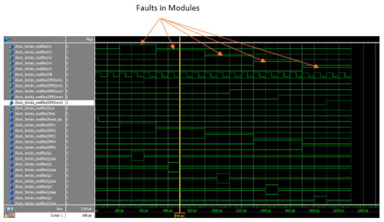
Figure 10.
Simulation result from ModelSim.
The proposed voter design was implemented using Xilinx Vivado tools targeting Kintex7 7k410tfbg676 device. Table 3 shows the resources utilization for the proposed design.

Table 3.
Implementation results of the proposed design.
4. Discussion
As shown in Table 1 and Table 2, 6MR is more reliable than 5MR, in the case λs = 5 λd, but 5MR is more reliable than 6MR in the case λs = 3 λd, although 5MR has a lower cost than 6MR (since it uses only five copies of the module M and not six copies as in 6MR). These results are counter intuitive, because reliability is expected to increase with redundancy. Several simulations are, then, applied on the model in Figure 3 using different transition rates from State 6 to State 4 (15 λd, 14 λd, 13 λd, and 12 λd). It is shown that the reason for this counter-intuitive result is mainly the “15 λd” transition from state 6 to State 4 in Figure 3. If λd is only one third λs, this rate will be relatively large.
This result can be considered to be another benefit for using FPGAs as they can be reconfigured with DPR based on the ratio between λs and λd. The failure rate (λ) is based on flux [15] that varies with the environment as it depends on several factors such as geographical location (latitude and longitude), altitude, and barometric pressure [27]. Therefore, depending on the environment where the system is expected to operate, the appropriate fault-tolerant architecture (5MR or 6MR) can be downloaded onto the FPGA using DPR.
5. Conclusions
Nowadays, FPGAs are used in a lot of applications such as automotive, space, and biomedical applications. SRAM-based FPGAs are susceptible to radiation-induced SEUs and MEUs. Several fault-tolerant techniques have been studied in previous works within the context of FPGA, namely scrubbing, TMR, as well as penta and hexa modular redundancy (5MR and 6MR). Scrubbing and TMR have problems with detecting MEUs.
The first contribution of this paper is a counter-intuitive result in some cases. We have shown that a 5MR fault-tolerant architecture can be more reliable than a 6MR architecture, because of the relative rate of DEUs as compared with that of SEUs. If the rate of SEUs is, at most, four times higher than that of DEUs, the 5MR architecture becomes more reliable (and has a lower cost) than the 6MR architecture. However, if the rate of SEUs is more than four times higher than that of the DEUs, the 6MR becomes more reliable than the 5MR, as reported in the literature. Markov models and the SHARPE software package were used in the analysis.
Then, in this paper, we focus on the 5MR architecture. Recovery circuits for this architecture can be found in the literature but they do not take into account the occurrence of SEUs/DEUs and the ability of DPR to recover from these upsets. A proposed error detection and recovery mechanism (voter) is designed taking into consideration transient faults and DPR; then, it is implemented using the Xilinx Vivado tool and the Kintex7 7k410tfbg676 device, and then this circuit is tested and it is shown that it performs correctly.
The third contribution of this paper is related to the concept of fault security. If the recovery mechanism suffers from any type of failure, it must alert the rest of the system in order not to use this incorrect output. Therefore, the developed design is further modified to produce a coded output.
As the technology evolves and the transistor size shrinks, the effect of multiple event upsets is expected to be more and more important, especially in harsh environments (e.g., space applications and nuclear plants). Therefore, future work should focus on fault-tolerant architectures other than 5MR that can withstand MEUs as well as SEUs. The ratio of MEUs to SEUs is expected to play an important role in determining the efficiency of these new architectures.
Author Contributions
M.N.S. is responsible for all the contributions in this paper; A.H. and H.H.A. discussed the conceptualization with M.N.S.; while I.A. and G.I.A. helped a little with the implementation. All authors have read and agreed to the published version of the manuscript.
Funding
This research received no external funding.
Acknowledgments
The authors would like to thank Tarek K. Refaat for his contributions to this research.
Conflicts of Interest
The authors declare no conflict of interest.
References
- Shreejith, S.; Fahmy, S.A.; Lukasiewycz, M. Reconfigurable computing in next-generation automotive networks. IEEE Embed. Syst. Lett. 2013, 5, 12–15. [Google Scholar] [CrossRef]
- Gabrick, M.; Nicholson, R.; Winters, F.; Young, B.; Patton, J. FPGA considerations for automotive applications. SAE Tech. Pap. 2006. [Google Scholar] [CrossRef]
- Rech, P.; Galliere, J.-M.; Girard, P.; Griffoni, A.; Boch, J.; Wrobel, F.; Saigne, F.; Dilillo, L. Neutron-induced multiple bit upsets on two commercial SRAMs under dynamic-stress. IEEE Trans. Nucl. Sci. 2012, 59, 893–899. [Google Scholar] [CrossRef]
- Farias, M.S.; Martins, R.H.S.; Teixeira, P.I.N.; Carvalho, P.V.R. FPGA-Based I&C Systems in Nuclear Plants. Chem. Eng. Trans. 2016, 53, 283–288. [Google Scholar]
- Dutta, A.; Touba, N.A. Multiple Bit Upset Tolerant Memory Using a Selective Cycle Avoidance Based SEC-DED-DAEC Code. In Proceedings of the 25th IEEE VLSI Test Symposium VTS’07, Berkeley, CA, USA, 6–10 May 2007. [Google Scholar]
- Constraints Guide; UG625; Xilinx: San Jose, CA, USA, 2012; Volume 14.
- Shaker, M.N.; Hussien, A.; Alkady, G.I.; Amer, H.H.; Adly, I. Mitigating the Effect of Multiple Event Upsets in FPGA-Based Automotive Applications. In Proceedings of the 8th IEEE Mediterranean Conference on Embedded Computing MECO, Budva, Montenegro, 10–14 June 2019. [Google Scholar]
- Afzaal, U.; Lee, J.A. FPGA-based design of a self-checking TMR voter. In Proceedings of the 27th IEEE International Conference on Field Programmable Logic and Applications FPL, Ghent, Belgium, 4–8 September 2017. [Google Scholar]
- Wakerly, J. Error Detecting Codes, Self-Checking Circuits and Applications; North-Holland: Amsterdam, The Netherlands, 1978. [Google Scholar]
- Siewiorek, D.P.; Swarz, R.S. Reliable Computer Systems: Design and Evaluatuion; A K Peters: Natick, MA, USA, 1998. [Google Scholar]
- Amer, H.H. Strongly Fault Secure Switch for Self-Purging Systems. In Proceedings of the Twentieth Annual Asilomar Conference on Signals, Systems and Computers, Monterey, CA, USA, 10–12 November 1986; pp. 312–316. [Google Scholar]
- Sterpone, L.; Ullah, A. On the Optimal Reconfiguration Times for TMR Circuits on SRAM Based FPGAs. In Proceedings of the NASA/ESA Conference on Adaptive Hardware and Systems AHS, Torino, Italy, 24–27 June 2013. [Google Scholar]
- Terada, R.; Watanabe, M. Error injection analysis for triple modular and penta-modular redundancies. In Proceedings of the 6th IEEE International Symposium on Next Generation Electronics ISNE, Keelung, Taiwan, 23–25 May 2017. [Google Scholar]
- Alkady, G.I.; Daoud, R.M.; Amer, H.H.; Adly, I.; Halawa, H.H.; Abdelhalim, M.B. Highly reliable controller implementation using a network-based fully reconfigurable FPGA for industrial applications. In Proceedings of the 22nd IEEE International Conference on Emerging Technologies and Factory Automation ETFA, Limassol, Cyprus, 12–15 September 2017. [Google Scholar]
- Dos Santos, A.F.; Tambara, L.A.; Benevenuti, F.; Tonfat, J.; Kastensmidt, F.L. Applying TMR in hardware accelerators generated by high-level synthesis design flow for mitigating multiple bit upsets in SRAM-based FPGAs. In Proceedings of the International Symposium on Applied Reconfigurable Computing ARC, Delft, The Netherlands, 3–7 March 2017; pp. 202–213. [Google Scholar]
- DUKE Sharp Portal. Available online: http://sharpe.pratt.duke.edu (accessed on 20 November 2020).
- Tonfat, J.; Kastensmidt, F.L.; Rech, P.; Reis, R.; Quinn, H.M. Analyzing the Effectiveness of a Frame-Level Redundancy Scrubbing Technique for SRAM-based FPGAs. IEEE Trans. Nucl. Sci. 2015, 62, 3080–3087. [Google Scholar] [CrossRef]
- Tambara, L.A.; Kastensmidt, F.L.; Medina, N.H.; Added, N.; Aguiar, V.A.P.; Guazzelli, M. Heavy Ions Induced Single Event Upsets Testing of the 28 nm Xilinx Zynq-7000 All Programmable SoC. In Proceedings of the IEEE Radiation Effects Data Workshop REDW, Boston, MA, USA, 13–17 December 2015. [Google Scholar]
- Trivedi, K.; Bobbio, A. Reliability and Availability Engineering—Modeling, Analysis, and Applications; Cambridge University Press: Cambridge, UK, 2017. [Google Scholar]
- Lala, P.K. Fault Tolerant & Fault Testable Hardware Design; Prentice Hall: Upper Saddle River, NJ, USA, 1985. [Google Scholar]
- Peter Jeppesen, B.; Rajamani, M.; Mark Smith, K. Enhancing functional safety in FPGA-based motor drives. IEEE J. Eng. 2019, 2019, 4580–4584. [Google Scholar] [CrossRef]
- Andres Cardona, L.; Ferrer, C. AC_ICAP: A Flexible High Speed ICAP Controller. Int. J. Reconfig. Comput. 2015, 2015, 1–15. [Google Scholar] [CrossRef] [PubMed][Green Version]
- Luckow, A.; Cook, M.; Ashcraft, N.; Weill, E.; Djerekarov, E.; Vorster, B. Deep Learning in the Automotive Industry: Applications and Tools. In Proceedings of the IEEE International Conference on Big Data, Washington, DC, USA, 5–8 December 2016. [Google Scholar]
- Wang, Y.; Xu, J.; Han, Y.; Li, H.; Li, X. DeepBurning: Automatic generation of FPGA-based learning accelerators for the neural network family. In Proceedings of the 53rd Annual Design Automation Conference DAC, Austin, TX, USA, 5–9 June 2016. [Google Scholar]
- Lee, D.S.; Wirthlin, M.; Swift, G.; Le, A.C. Single-Event Characterization of the 28 nM Xilinx Kintex-7 Field-Programmable Gate Array under Heavy Ion Irradiation. In Proceedings of the IEEE Radiation Effects Data Workshop REDW, Paris, France, 13–17 July 2014. [Google Scholar]
- Gauer, C.; LaMeres, B.J.; Racek, D. Spatial Avoidance of Hardware Faults using FPGA Partial Reconfiguration of Tile-Based Soft Processors. In Proceedings of the IEEE Aerospace Conference, Big Sky, MT, USA, 6–13 March 2010. [Google Scholar]
- Nicolaidis, M. Soft Errors in Modern Electronic Systems; Springer: New York, NY, USA, 2010; p. 41. [Google Scholar]
Publisher’s Note: MDPI stays neutral with regard to jurisdictional claims in published maps and institutional affiliations. |
© 2020 by the authors. Licensee MDPI, Basel, Switzerland. This article is an open access article distributed under the terms and conditions of the Creative Commons Attribution (CC BY) license (http://creativecommons.org/licenses/by/4.0/).