The Path Planning of Synchronous Cooperative Motion Control between Robot and Positioner for Complex Space Curve Processing


Abstract
1. Introduction
- (1)
- Motion path planning of the robot and the positioner: The current research focus is on the path planning of the robot and the positioner during the processing path of the workpiece. To ensure processing accuracy, Jouaneh et al. [10] firstly proposed a processing strategy of collaborative motion between positioner and robot. This strategy used the method of constant speed to track the path to make the 5-DOF robot and 2-DOF positioner move simultaneously. Shi et al. [18] studied robots’ and positioners’ trajectory planning in the process of coordinated welding of intersecting tubes, and Shi et al. proposed an algorithm for generating motion codes for welding intersecting tubes. This algorithm used the welding speed control as the basis of the industrial robot’s trajectory planning, and it can prevent the cable winding up. Wu et al. [12] proposed a trajectory planning strategy for the coordinated movement of a 6-DOF manipulator and a 2-DOF positioner. This strategy used AutoCAD for offline trajectory planning and then converted them into robot language. Liu et al. [15] proposed a new laser scanning based non-ideal tube intersection curve robot welding path planning method. This method integrated the generation of a laser scanning trajectory and the path planning of non-ideal tube welding to avoid the negative impact of the uphill and downhill welding quality on the welding. The research focus of these scholars is the path planning of robots and positioners on the processing path, and the path before and after the processing path is not systematically planned.
- (2)
- Solving the pose information of complex space curves and robot end tools: The current research focuses on the curve dispersion and the determination of the normal direction of the tool at the end of the robot [19,20]. Liu et al. [21] suggested a pose planning method for the welding torch at the normal plane dividing angle. This method can position the welding torch at the center of two cylinders and the intersecting curve. Compared to the traditional axial rotating plane dividing angle method, it can ensure the welding torch is always in the best pose. In the process of welding trajectory planning, according to the limitation of string error, Liu et al. [22] introduced a discrete algorithm of fitting intersection curves based on the principle of equal arc length and the position and orientation of the welding torch were given in the form of the matrix. This algorithm can effectively reduce the fluctuation of the feed rate. Liu et al. [23] proposed a discrete method for robot offline programming welding. According to the string error limit and the principle of equal arc length, a discrete method for the intersection curve of the tube was given. This algorithm solved the linearity of the complex curve in the robot control system and guarantees the accuracy of robot intersection curve welding. In the process of solving the pose information, the change of the tool orientation during the entire processing process is not considered, which often makes the tool orientation change too large. In the welding process, when the change of the torch orientation is random, it will make the orientation of the end of the welding torch change too much, resulting in the weakening of the interaction degree of the weld pool and the control force on the arc [24,25]. Therefore, the width and residual height of the weld are uneven, and the weld width at the back is discontinuous.
- (3)
- Cooperative motion control of robots and positioners: Many scholars often regard robot and positioner as two independent working units for motion control. Gao et al. [14] proposed a new strategy to optimize the motion of robots and positioners in redundant robot systems. This strategy transformed the continuous problems in the original motion for discrete problems and described all possible movements of the robot and positioner in a combined manner. Using this method can improve computational efficiency and also take collision constraints into account. Shao et al. [16] established a coupled mathematical model of arc welding robot and positioner for the coordinated motion of the arc welding robot and positioner. This model can strongly couple the arc welding robot and the positioner during the process of welding movement. The motion process was simulated under the MATLAB simulation environment to verify that the model established can precisely reflect the accuracy of the coupling motion of the arc welding robot positioner. My et al. [17] proposed a new inverse kinematics solution algorithm. The algorithm unifies two kinematic chains of the robot and the positioner into an open redundant serial kinematic chain of the entire robot system. This algorithm minimized the errors between the ideal welding path and the actual welding path and effectively improves the positioning accuracy of the end tool. Many scholars often regard robot and positioner as two independent working units for motion control. At this time, the relationship between the robot and the positioner is a master–slave relationship; when the robot reaches the first processing point and returns to zero, the positioner is in a stagnation waiting state [26]. This waiting time extends the entire cycle of the robot and the positioner’s coordinated motion, making the cooperative motion cycle time longer and less efficient.
- (1)
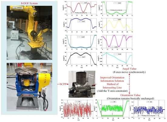
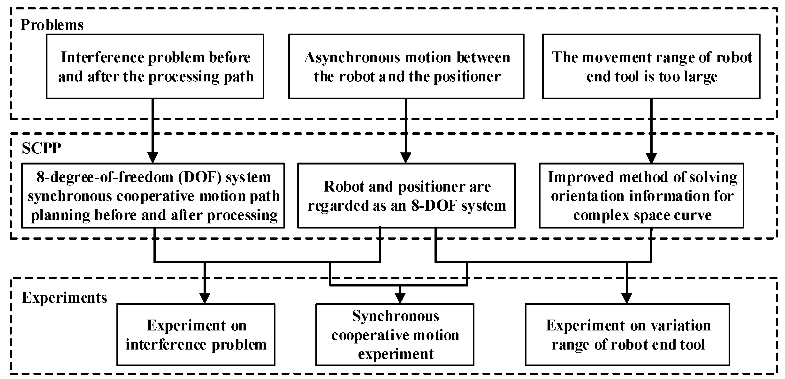
- The robot and the positioner are regarded as a complete 8-DOF system to solve the problem of asynchronous motion between the robot and the positioner so that there is no master–slave relationship between the robot and the positioner, but a synchronous cooperation. The freedom of movement of the robot and the positioner can be fully utilized, which improves the processing efficiency;
- (2)
- The 8-DOF system model is used for path planning through rigorous mathematical derivation to calculate the poses of the two transition points, and then the motion path of the 8-DOF system before and after processing is planned. This planning method has a small amount of calculation and strong practicality. It can be applied to the robot and the positioner in different poses and different sizes of workpieces. The robot and the positioner are ensured synchronous movement without interference;
- (3)
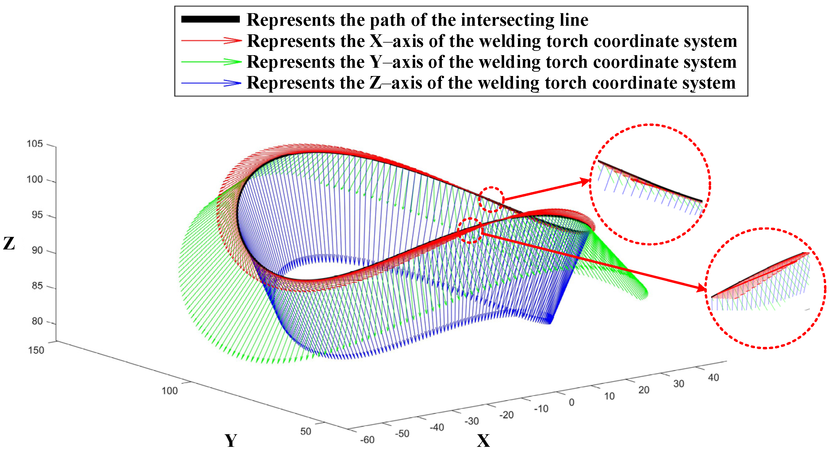
- An improved method to solve the orientation information of a complex space curve is proposed, which causes the rotation range of the six axes of the robot to decrease during welding the intersecting line, and at the same time, keeps the welding torch orientation basically unchanged. This method has strong regularity in adjusting the welding torch orientation. During the welding process, it has high control over the welding pool, and always maintains the relative balance of the welding pool distribution, and finally obtains full penetration and beautiful continuous post-weld welding seam width and consistent forming effect.
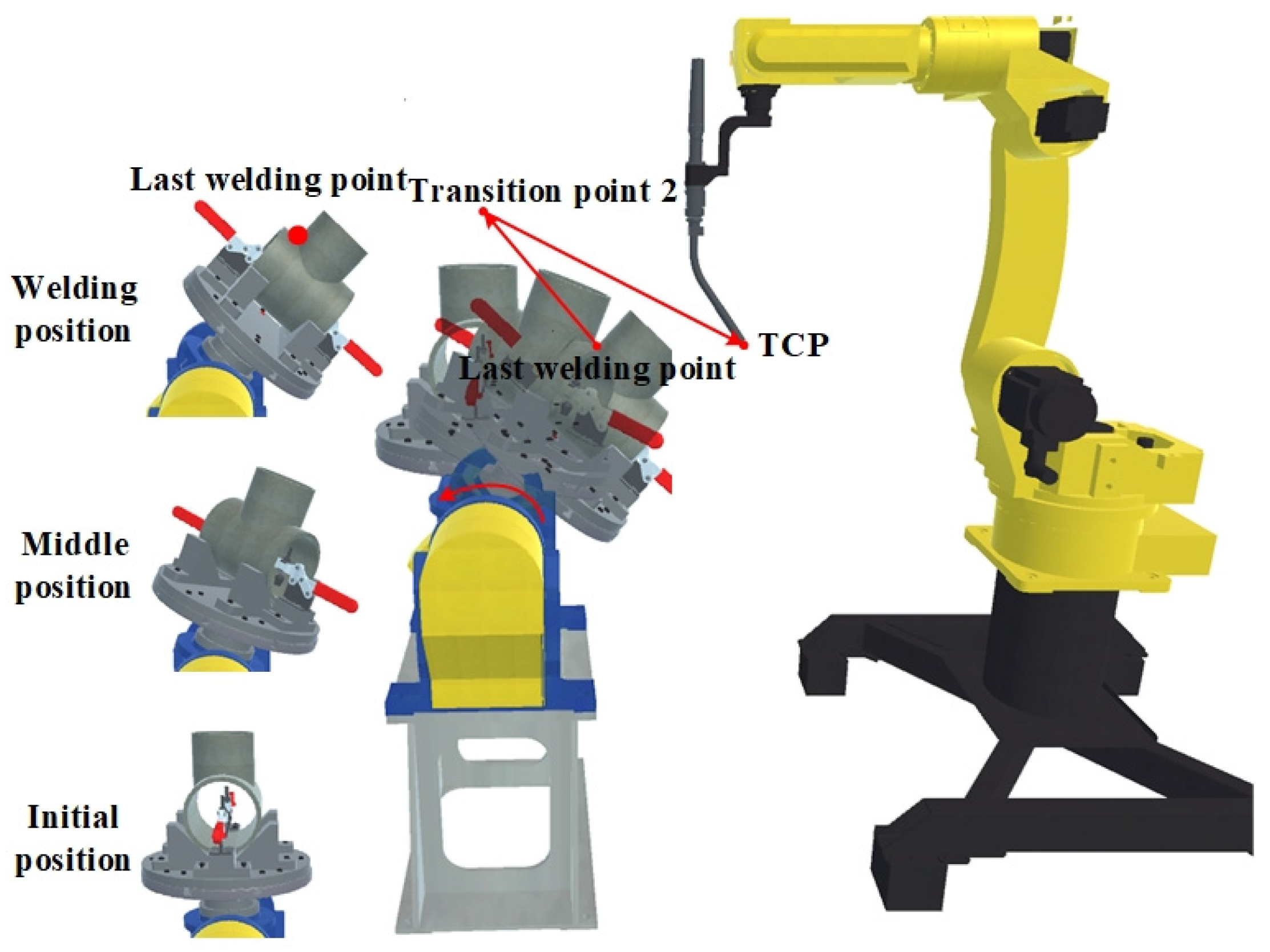
2. 8-DOF System Synchronous Cooperative Motion Path Planning before and after Processing
2.1. 8-DOF System Synchronous Cooperative Motion Path Planning before Processing
2.2. 8-DOF System Synchronous Cooperative Motion Path Planning after Processing
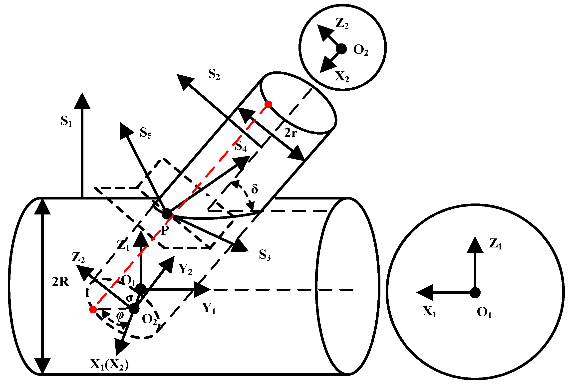
3. Improved Method of Solving Orientation Information for Complex Space Curve
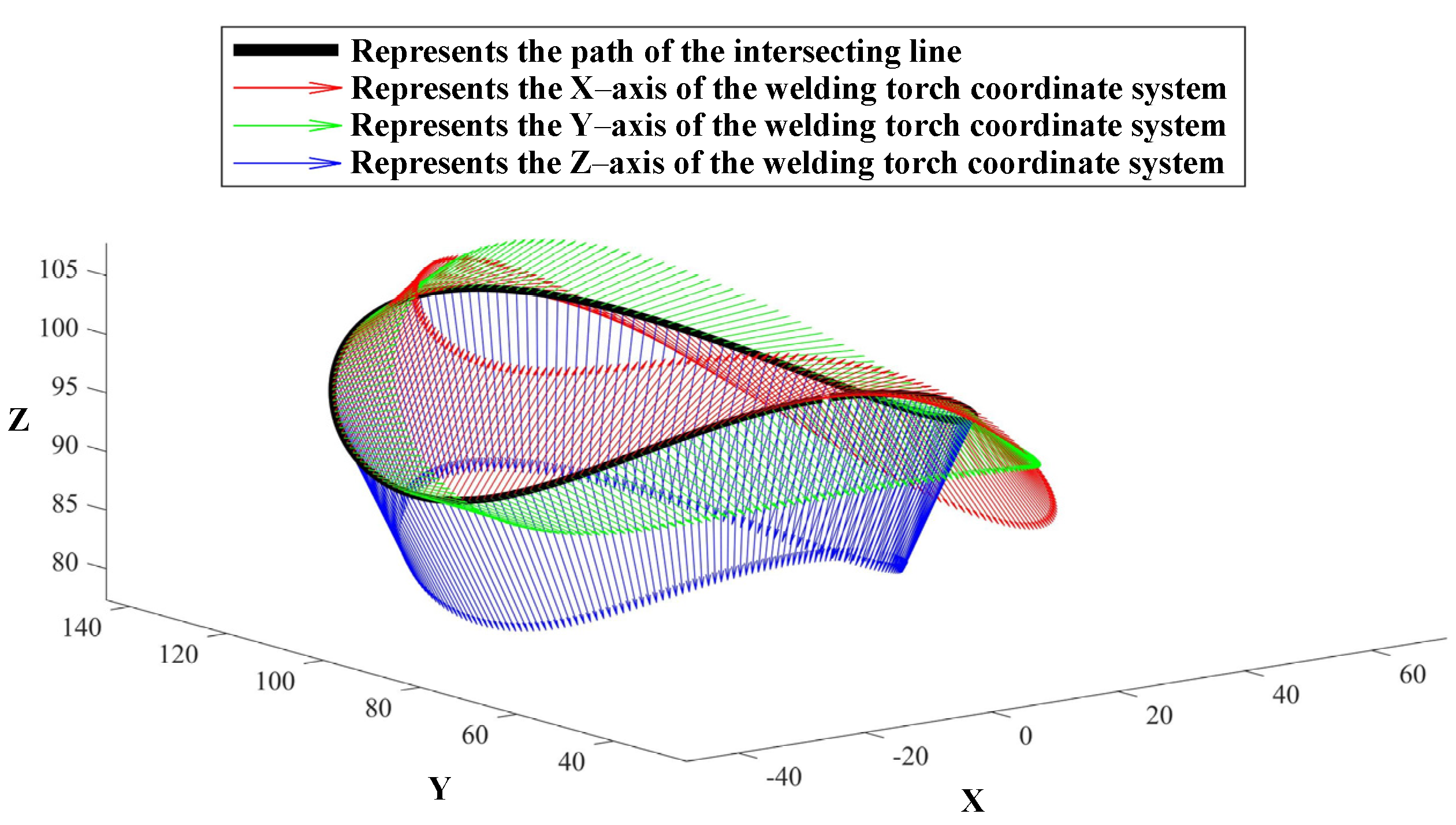
3.1. The Position Information Solution of Complex Space Curve (Intersecting Line)
3.2. Traditional Method of Solving Orientation Information for Complex Space Curve (Intersecting Line)
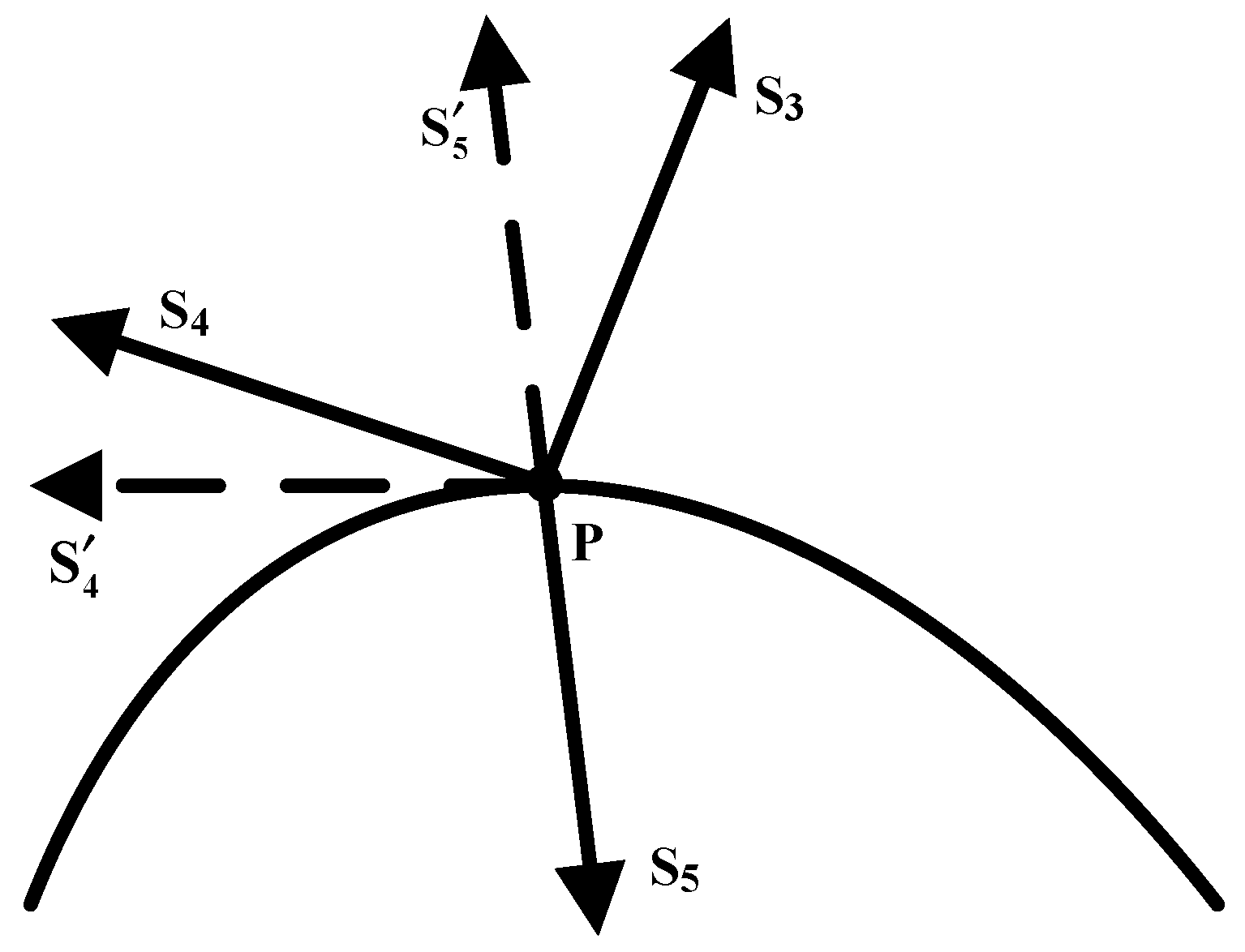
3.3. Improved Method of Solving Orientation Information for Complex Space Curve (Intersecting Line)
- (1)
- The vector can be obtained by solving Formula (23);
- (2)
- Reverse to get the unit vector S5, which is the Z-axis unit vector of the welding torch coordinate system;
- (3)
- The vector is preliminarily determined, it can help prevent the end welding torch’s orientation from changing too much during the movement;
- (4)
- Get the X-axis unit vector S3 of welding torch coordinate system: ;
- (5)
- Get the Y-axis unit vector S4 of welding torch coordinate system: .
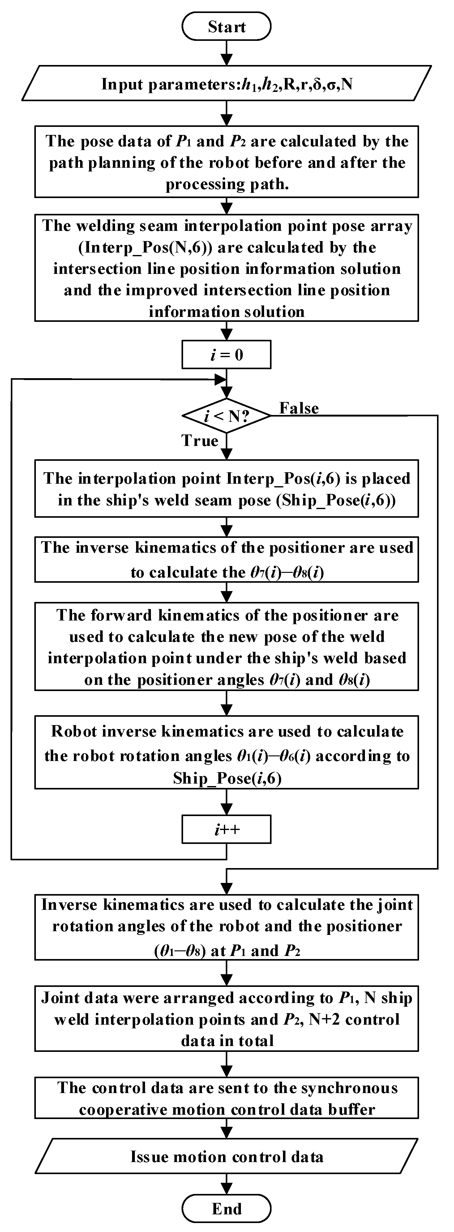
4. Process of SCPP Algorithm of Robot and Positioner
- (1)
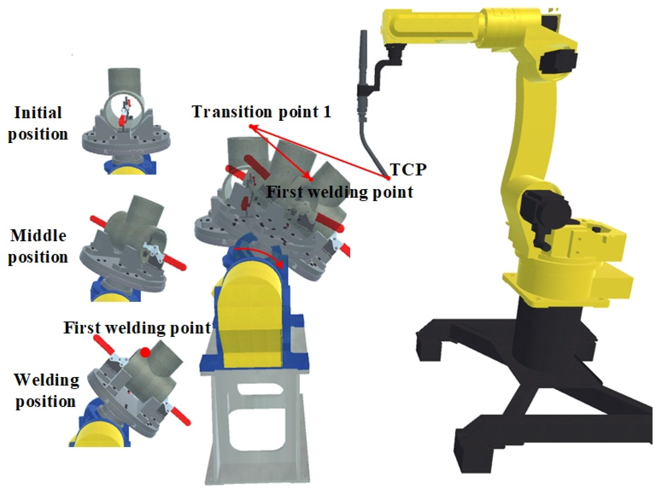
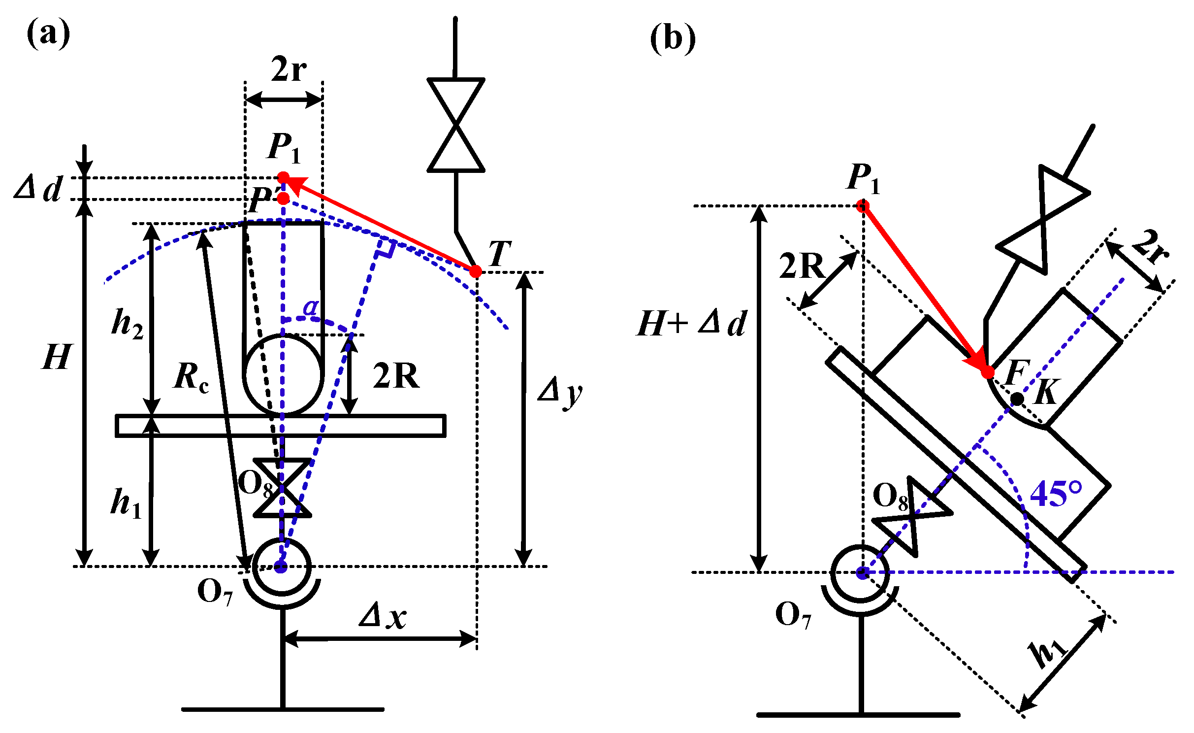
- The position of the transition point 1 and the transition point 2 in the robot coordinate system can be calculated by the input parameters;
- (2)
- Intersection line position information solution and improved intersection line orientation information solution method to obtain N weld interpolation points’ pose;
- (3)
- The positioner sets the N welding seam interpolation points to the ship-shaped weld seam pose;
- (4)
- The inverse kinematics of the positioner calculates joint 7 and 8 rotation angle values when the N welding seam interpolation points are at the ship’s seam pose;
- (5)
- The positive kinematics of the positioner calculates the new pose of the N ship-shaped seam interpolation points in the robot coordinate system based on joint 7 and 8 rotation angle values;
- (6)
- The inverse kinematics of the robot calculates the joint 1–6 rotation angles at the interpolation points of the N ship welds;
- (7)
- The inverse kinematics of the robot and the positioner calculates the joint 1–8 rotation angles of the robot and the positioner at transition point 1 and transition point 2;
- (8)
- In the synchronous coordinated movement of the whole robot and the positioner, there are N discrete points poses of welding seams, transition point 1 pose, transition point 2 pose, and a total of N + 2 control data. Following the sequence, the robot and the positioner move from zero to transition point 1, then move to N ship welding interpolation points, and then move to transition point 2, and finally return to the zero position, the control data will be stored in the synchronous cooperative control data buffer, and finally distributed successively.
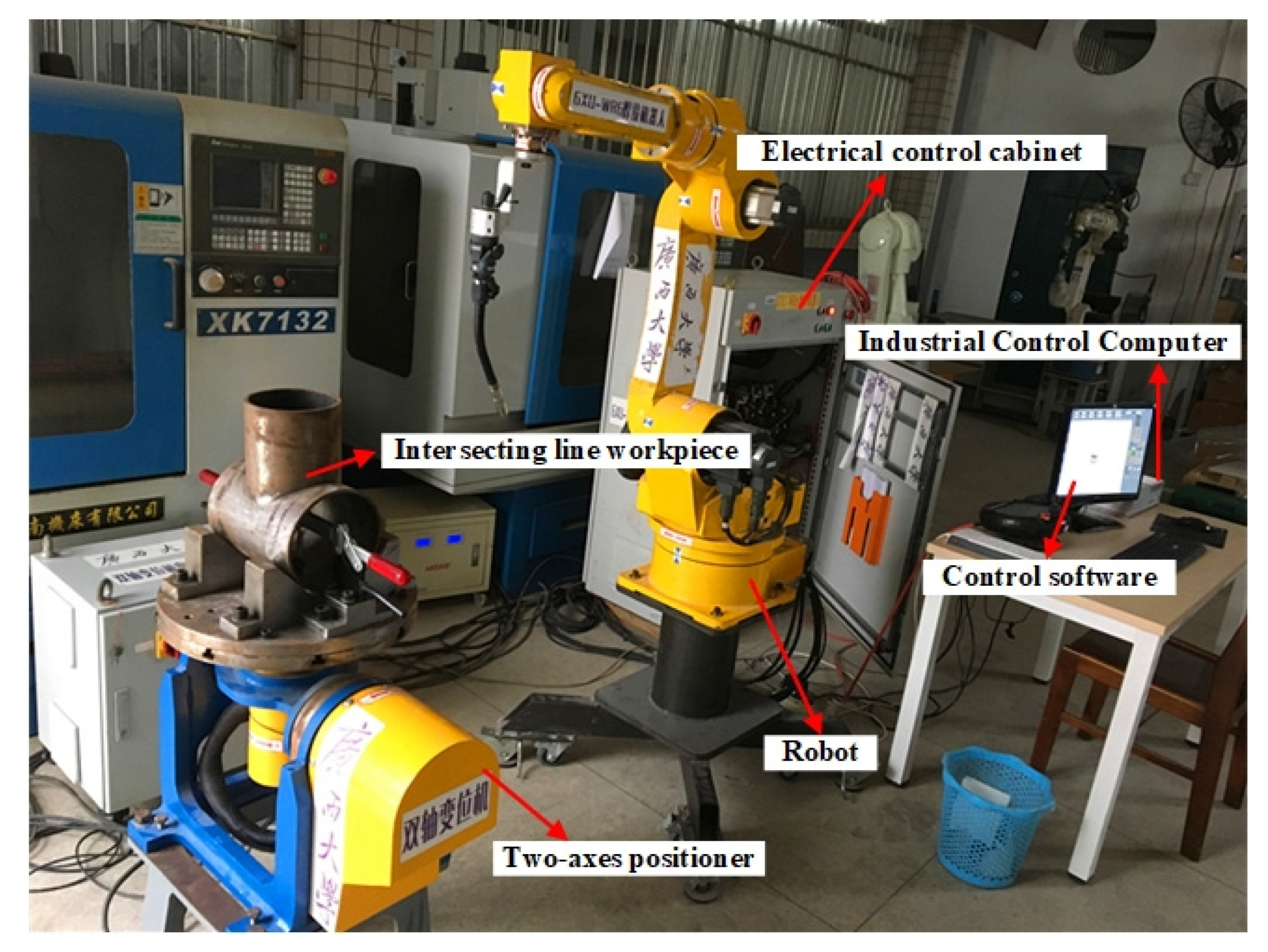
5. Experimental Results and Discussion
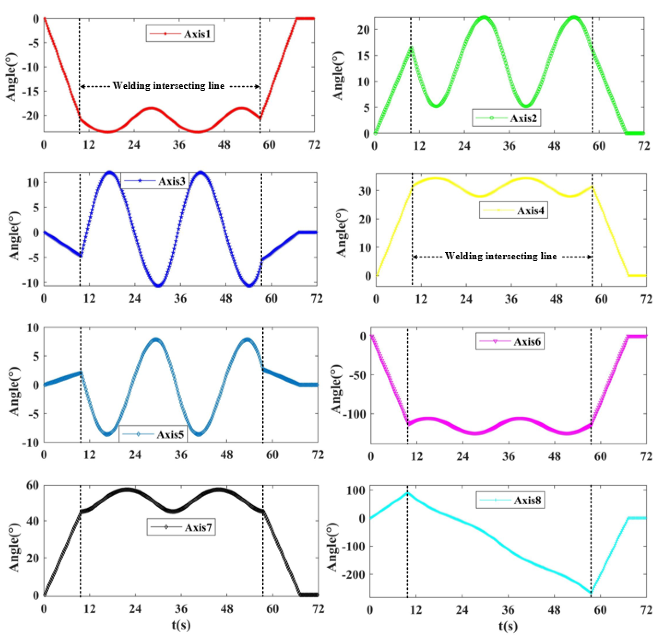
5.1. Traditional Cooperative Motion Process (Positioner Is Active and Robot Is Driven)
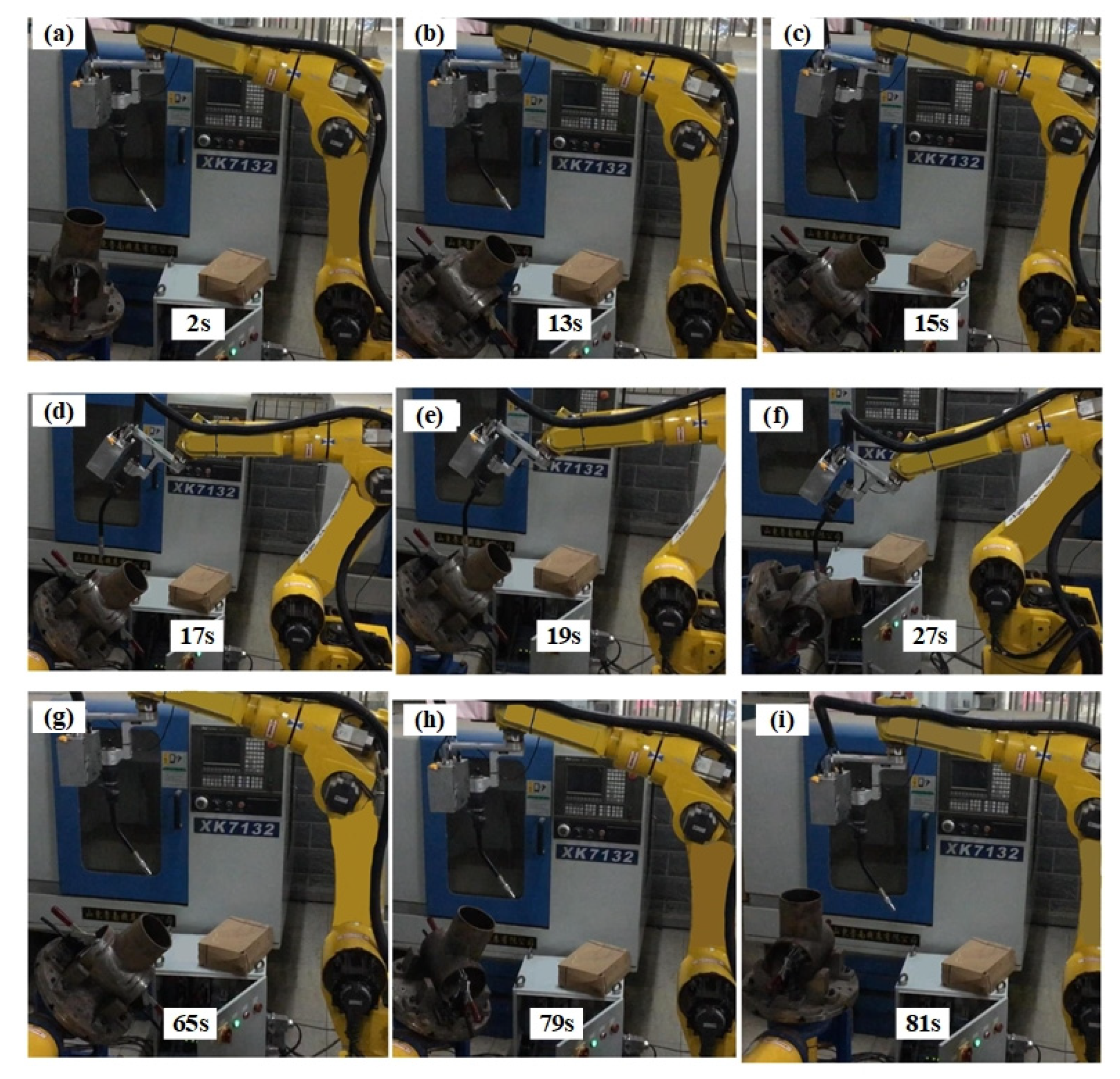
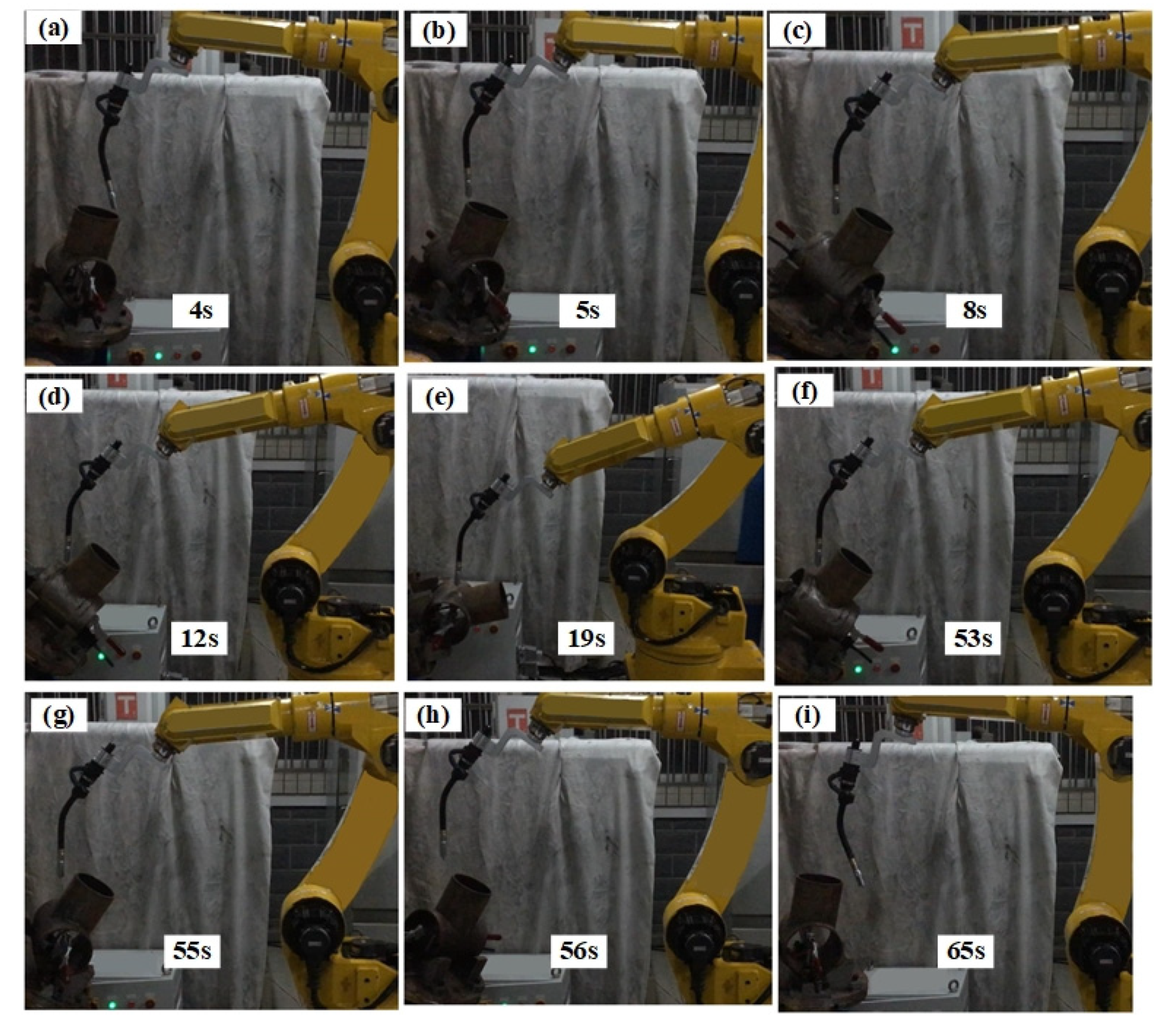
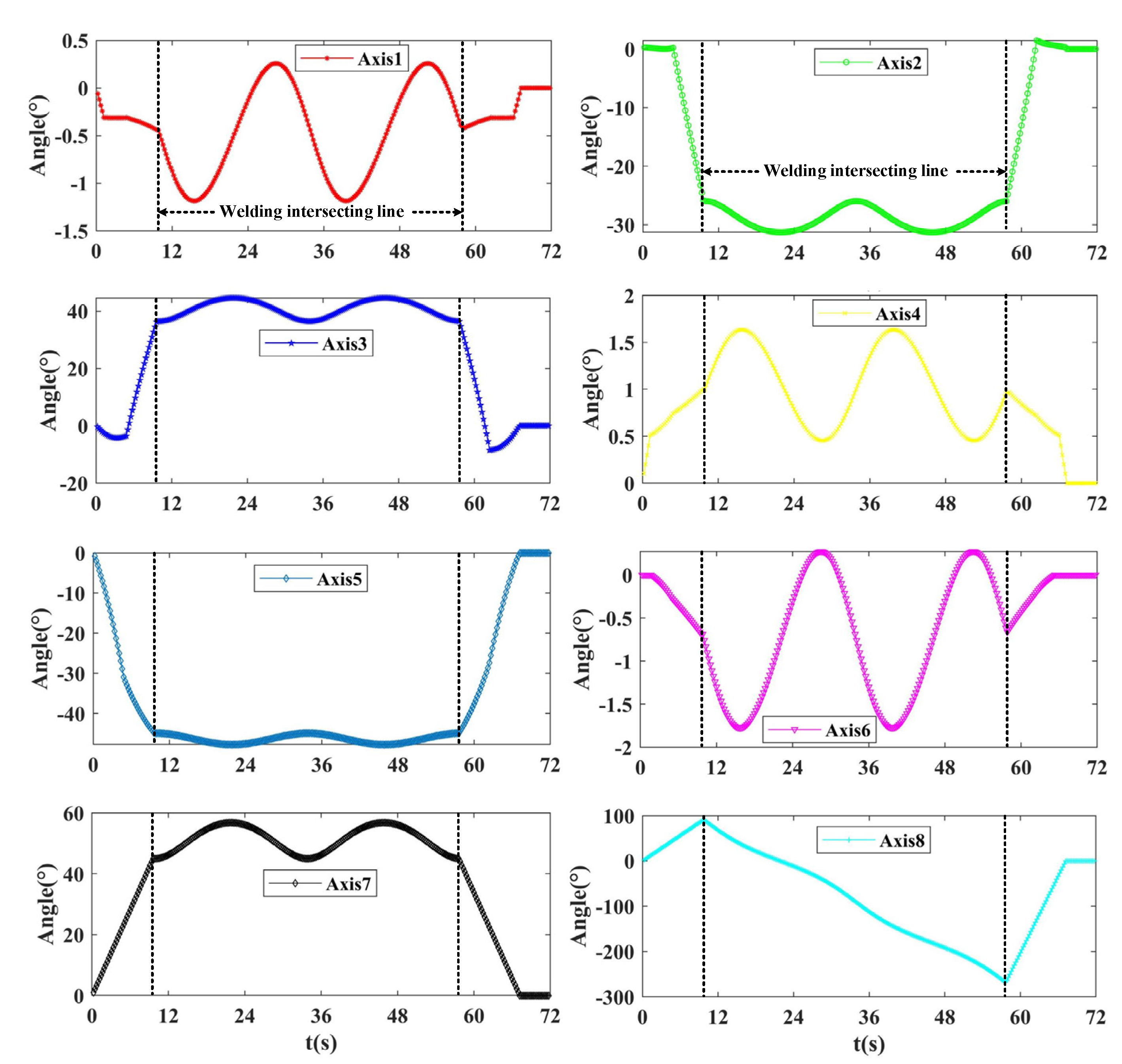
5.2. Synchronous Cooperative Motion Process
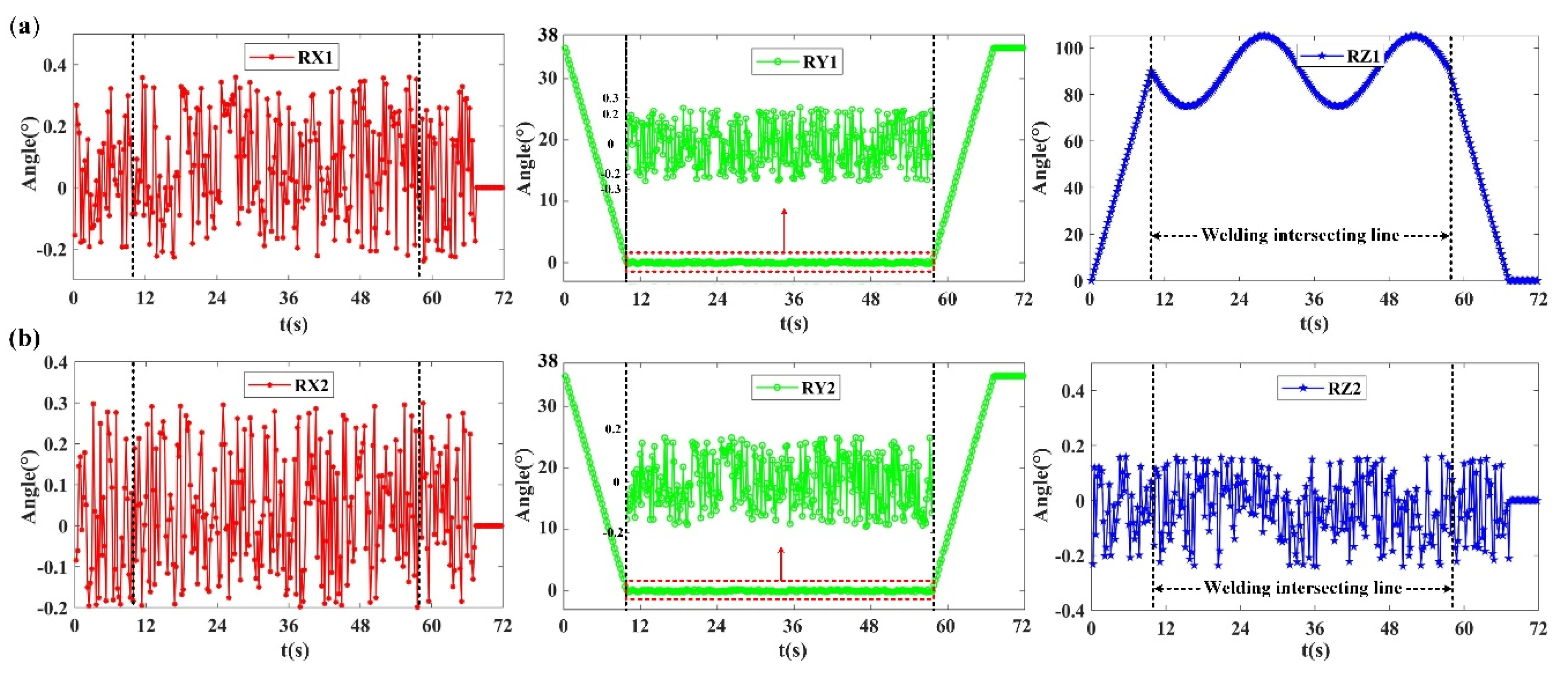
5.3. Comparison of Two Orientation Information Methods
5.4. Validation of SCPP Algorithm Effectiveness and Robustness
6. Conclusions
Author Contributions
Funding
Acknowledgments
Conflicts of Interest
References
- Bloch, V.; Degani, A.; Bechar, A. A methodology of orchard architecture design for an optimal harvesting robot. Biosyst. Eng. 2018, 166, 126–137. [Google Scholar] [CrossRef]
- Waiboer, R.; Aarts, R.; Jonker, B. Velocity dependence of joint friction in robotic manipulators with gear transmissions. In Proceedings of the ECCOMAS Thematic Conference Multibody Dynamics 2005, Advances in Computational Multibody Dynamics, Madrid, Spain, 21 July 2005. [Google Scholar]
- Wu, H.; Bi, Z.; Su, M.; Zhang, P.; He, Y.; Guan, Y. Coordinated motion planning with calibration and offline programming for a manipulator-positioner system. In Proceedings of the 2014 IEEE International Conference on Robotics and Biomimetics (ROBIO 2014), Bali, Indonesia, 5–10 December 2014; pp. 1094–1099. [Google Scholar]
- Wang, H.; Guo, D.; Liang, X.; Chen, W.; Hu, G.; Leang, K.K. Adaptive Vision-Based Leader–Follower Formation Control of Mobile Robots. IEEE Trans. Ind. Electron. 2017, 64, 2893–2902. [Google Scholar] [CrossRef]
- Pellegrinelli, S.; Pedrocchi, N.; Tosatti, L.M.; Fischer, A.; Tolio, T. Multi-robot spot-welding cells for car-body assembly: Design and motion planning. Robot. Comput. Manuf. 2017, 44, 97–116. [Google Scholar] [CrossRef]
- Hou, Z.; Ma, S.; Zeng, Q.; Li, A. Kinematics analysis and self-collision detection of Truss type multi-robot cooperative welding platform. Procedia CIRP 2019, 81, 488–493. [Google Scholar] [CrossRef]
- Sharma, A.; Zanotti, P.; Musunur, L.P. Enabling the Electric Future of Mobility: Robotic Automation for Electric Vehicle Battery Assembly. IEEE Access 2019, 7, 170961–170991. [Google Scholar] [CrossRef]
- Lan, J.; Xie, Y.; Liu, G.; Cao, M. A Multi-Objective Trajectory Planning Method for Collaborative Robot. Electronics 2020, 9, 859. [Google Scholar] [CrossRef]
- Ogbemhe, J.; Mpofu, K.; Tlale, N. Optimal Trajectory Scheme for Robotic Welding Along Complex Joints Using a Hybrid Multi-Objective Genetic Algorithm. J. Robot. Mach. Learn. 2020. [Google Scholar] [CrossRef]
- Jouaneh, M.; Dornfeld, D. A kinematic approach for coordinated motion of a robot and a positioning table. J. Manuf. Syst. 1988, 7, 307–314. [Google Scholar] [CrossRef]
- Totala, N.; Bhutada, S.; Katruwar, N. Design, Manufacturing and Testing of Circular Welding Positioner. Int. J. Eng. 2014, 10, 8–15. [Google Scholar]
- Wang, H.; Fu, W.; Ou, H.; Tang, X. Path planning and kinematics simulation of surfacing cladding for hot forging die. In MATEC Web of Conference; EDP Sciences: Glasgow, UK, 2015; Volume 21, p. 08005. [Google Scholar] [CrossRef]
- Yang, Q.; Luo, D.-Y. Design of Welding Control System Based on Robot. DEStech Trans. Eng. Technol. Res. 2017. [Google Scholar] [CrossRef]
- Gao, J.; Pashkevich, A.; Caro, S. Optimization of the robot and positioner motion in a redundant fiber placement workcell. Mech. Mach. Theory 2017, 114, 170–189. [Google Scholar] [CrossRef]
- Liu, Y.; Tian, X. Robot path planning with two-axis positioner for non-ideal sphere-pipe joint welding based on laser scanning. Int. J. Adv. Manuf. Technol. 2019, 105, 1295–1310. [Google Scholar] [CrossRef]
- Changchun, S.; Shuiming, L.; Ying, H. Coordinated motion analysis and simulation of arc welding robot and positioner. In Journal of Physics: Conference Series; IOP Publishing: Daqing, China, 2018; Volume 1168, p. 022032. [Google Scholar] [CrossRef]
- My, C.A.; Bien, D.X.; Tung, B.H.; Hieu, L.C.; Cong, N.V.; Hieu, T.V. Inverse kinematic control algorithm for a welding robot-positioner system to trace a 3D complex curve. Rabat, Morocco, International Conference on Advanced Communication Technologies and Networking. In Proceedings of the 2019 International Conference on Advanced Technologies for Communications (ATC), Hanoi, Vietnam, 17–19 October 2019; pp. 319–323. [Google Scholar]
- Shi, L.; Tian, X.; Zhang, C. Automatic programming for industrial robot to weld intersecting pipes. Int. J. Adv. Manuf. Technol. 2015, 81, 2099–2107. [Google Scholar] [CrossRef]
- Fang, H.; Ong, S.; Nee, A. Robot path planning optimization for welding complex joints. Int. J. Adv. Manuf. Technol. 2016, 90, 3829–3839. [Google Scholar] [CrossRef]
- Fang, H.C.; Ong, S.K.; Nee, A. Adaptive pass planning and optimization for robotic welding of complex joints. Adv. Manuf. 2017, 5, 93–104. [Google Scholar] [CrossRef]
- Liu, Y. Pose Planning for the End-effector of Robot in the Welding of Intersecting Pipes. Chin. J. Mech. Eng. 2011, 24, 264–270. [Google Scholar] [CrossRef]
- Liu, Y.; Shi, L.; Tian, X. Weld seam fitting and welding torch trajectory planning based on NURBS in intersecting curve welding. Int. J. Adv. Manuf. Technol. 2017, 95, 2457–2471. [Google Scholar] [CrossRef]
- Liu, Y.; Tang, Q.; Tian, X. A discrete method of sphere-pipe intersecting curve for robot welding by offline programming. Robot. Comput. Manuf. 2019, 57, 404–411. [Google Scholar] [CrossRef]
- Zhang, G.; Shi, Y.; Gu, Y.; Fan, D. Welding torch attitude-based study of human welder interactive behavior with weld pool in GTAW. Robot. Comput. Manuf. 2017, 48, 145–156. [Google Scholar] [CrossRef]
- Li, J.; Li, H.; Wei, H.L.; Gao, Y. Effect of torch position and angle on welding quality and welding process stability in Pulse on Pulse MIG welding–brazing of aluminum alloy to stainless steel. Int. J. Adv. Manuf. Technol. 2015, 84, 705–716. [Google Scholar] [CrossRef]
- Zhou, B.; Xu, L.; Meng, Z.; Dai, X. Kinematic cooperated welding trajectory planning for master-slave multi-robot systems. In Proceedings of the 2016 35th Chinese Control Conference (CCC), Chengdu, China, 27–29 July 2016. [Google Scholar]


| Transition Point | P1 | P2 |
|---|---|---|
| Axis 1 (°) | 0.096 | 0.083 |
| Axis 2 (°) | −0.756 | 0.490 |
| Axis 3 (°) | −2.662 | −7.630 |
| Axis 4 (°) | 0.072 | 0.066 |
| Axis 5 (°) | −31.583 | −27.861 |
| Axis 6 (°) | 0.037 | 0.056 |
| Axis 7 (°) | 24.795 | 24.315 |
| Axis 8 (°) | 49.589 | 48.631 |
| Angle | TA_Min | TA_Max | IA_Min | IA_Max | ΔTA | ΔIA |
|---|---|---|---|---|---|---|
| Axis 1 (°) | −23.5 | −18.6 | −1.2 | 0.3 | 4.9 | 1.5 |
| Axis 2 (°) | 5.2 | 22.3 | −31.3 | −25.8 | 17.2 | 5.5 |
| Axis 3 (°) | −10.7 | 12.0 | 36.3 | 44.6 | 22.7 | 8.4 |
| Axis 4 (°) | 28.0 | 34.3 | 0.5 | 1.6 | 6.3 | 1.2 |
| Axis 5 (°) | −8.6 | 7.9 | −47.8 | −44.9 | 16.5 | 2.9 |
| Axis 6 (°) | −125.1 | −105.5 | −1.8 | 0.3 | 19.6 | 2.0 |
| Axis 7 (°) | 45.0 | 56.8 | 45.0 | 56.8 | 11.8 | 11.8 |
| Axis 8 (°) | −270.1 | 90.0 | −270.1 | 90.0 | 360.1 | 360.0 |
| Rotation | RX (°) | RY (°) | RZ (°) |
|---|---|---|---|
| TR_Min | −0.382 | −0.231 | 73.163 |
| TR_Max | 0.222 | 0.263 | 105.072 |
| IR_Min | −0.311 | −0.171 | −0.185 |
| IR_Max | 0.192 | 0.153 | 0.196 |
| ΔTR | 0.604 | 0.494 | 31.909 |
| ΔIR | 0.503 | 0.324 | 0.381 |
| Position (X, Y, Z) (mm) | X = 1128.958 Y = −122.684 Z = 744.691 | X = 1228.958 Y = 0 Z = 744.691 | X = 1228.958 Y = −122.684 Z = 744.691 | X = 1128.958 Y = 100 Z = 744.691 | X = 1028.958 Y = −200 Z = 744.691 | |
|---|---|---|---|---|---|---|
| Mean of variation range by the SCPP (°) | axis 1 | 4.40 | 3.61 | 3.69 | 4.38 | 5.77 |
| axis 2 | 7.55 | 6.33 | 6.39 | 7.58 | 8.54 | |
| axis 3 | 16.35 | 16.65 | 16.60 | 16.36 | 15.91 | |
| axis 4 | 4.69 | 3.46 | 4.65 | 4.46 | 5.70 | |
| axis 5 | 8.70 | 10.45 | 10.27 | 8.78 | 6.39 | |
| axis 6 | 7.62 | 5.76 | 7.13 | 7.32 | 10.07 | |
| Mean of variation range by the traditional method (°) | axis 1 | 11.30 | 8.30 | 9.61 | 8.00 | 14.4 |
| axis 2 | 32.96 | 37.97 | 38.97 | 35.1 | 28.95 | |
| axis 3 | 47.50 | 57.43 | 61.58 | 46.03 | 40.95 | |
| axis 4 | 15.11 | 12.93 | 13.82 | 12.43 | 16.89 | |
| axis 5 | 34.92 | 42.09 | 43.364 | 35.44 | 29.46 | |
| axis 6 | 39.47 | 39.27 | 38.29 | 42.20 | 39.07 | |
| Position (X, Y, Z) (mm) | X = 1128.958 Y = −122.684 Z = 744.691 | X = 1228.958 Y = 0 Z = 744.691 | X = 1228.958 Y = −122.684 Z = 744.691 | X = 1128.958 Y = 100 Z = 744.691 | X = 1028.958 Y = −200 Z = 744.691 | |
|---|---|---|---|---|---|---|
| Reduction percentage of axes rotation range by SCPP (%) | axis 1 | 61.09 | 56.47 | 61.62 | 45.30 | 60.05 |
| axis 2 | 77.08 | 83.34 | 83.61 | 78.44 | 70.52 | |
| axis 3 | 65.58 | 71.00 | 73.04 | 64.46 | 61.14 | |
| axis 4 | 68.98 | 73.26 | 66.36 | 64.10 | 66.23 | |
| axis 5 | 75.07 | 75.18 | 76.31 | 75.23 | 78.29 | |
| axis 6 | 80.70 | 85.34 | 81.38 | 82.65 | 74.23 | |
| Parameters (R, r, h2) (mm) | R = 100 r = 40 h2 = 280 | R = 150 r = 40 h2 = 280 | R = 200 r = 70 h2 = 300 | R = 250 r = 100 h2 = 300 | R = 100 r = 40 h2 = 300 | |
|---|---|---|---|---|---|---|
| Mean of variation range by the SCPP (°) | axis 1 | 1.44 | 1.17 | 3.00 | 5.68 | 12.41 |
| axis 2 | 5.33 | 5.40 | 9.20 | 12.89 | 19.02 | |
| axis 3 | 8.19 | 6.82 | 10.89 | 14.74 | 22.15 | |
| axis 4 | 1.18 | 0.82 | 1.89 | 3.36 | 7.08 | |
| axis 5 | 2.86 | 1.42 | 1.69 | 1.85 | 3.13 | |
| axis 6 | 2.05 | 1.45 | 3.32 | 5.69 | 11.30 | |
| Mean of variation range by the traditional method (°) | axis 1 | 4.94 | 3.90 | 6.33 | 8.87 | 13.74 |
| axis 2 | 17.15 | 11.85 | 15.57 | 18.36 | 24.77 | |
| axis 3 | 22.68 | 15.24 | 20.46 | 25.16 | 36.38 | |
| axis 4 | 6.34 | 3.93 | 4.67 | 5.20 | 7.34 | |
| axis 5 | 16.49 | 10.29 | 12.33 | 13.13 | 15.97 | |
| axis 6 | 19.56 | 13.91 | 18.46 | 21.20 | 26.31 | |
| Parameters (R, r, h2) (mm) | R = 100 r = 40 h2 = 280 | R = 150 r = 40 h2 = 280 | R = 200 r = 70 h2 = 300 | R = 250 r = 100 h2 = 300 | R = 100 r = 40 h2 = 300 | |
|---|---|---|---|---|---|---|
| Reduction percentage of axes rotation range by SCPP (%) | axis 1 | 70.77 | 70.10 | 52.65 | 35.91 | 9.73 |
| axis 2 | 68.90 | 54.40 | 40.87 | 29.81 | 23.21 | |
| axis 3 | 63.88 | 55.24 | 46.75 | 41.42 | 39.11 | |
| axis 4 | 81.36 | 79.18 | 59.49 | 35.30 | 3.57 | |
| axis 5 | 82.67 | 86.22 | 86.32 | 85.94 | 80.39 | |
| axis 6 | 89.54 | 89.59 | 82.02 | 73.15 | 57.05 | |
Publisher’s Note: MDPI stays neutral with regard to jurisdictional claims in published maps and institutional affiliations. |
© 2020 by the authors. Licensee MDPI, Basel, Switzerland. This article is an open access article distributed under the terms and conditions of the Creative Commons Attribution (CC BY) license (http://creativecommons.org/licenses/by/4.0/).
Share and Cite
Chen, L.; Wang, Z.; Mo, Y.; Pan, H. The Path Planning of Synchronous Cooperative Motion Control between Robot and Positioner for Complex Space Curve Processing. Electronics 2020, 9, 1917. https://doi.org/10.3390/electronics9111917
Chen L, Wang Z, Mo Y, Pan H. The Path Planning of Synchronous Cooperative Motion Control between Robot and Positioner for Complex Space Curve Processing. Electronics. 2020; 9(11):1917. https://doi.org/10.3390/electronics9111917
Chicago/Turabian StyleChen, Lin, Ziwei Wang, Yuliang Mo, and Haihong Pan. 2020. "The Path Planning of Synchronous Cooperative Motion Control between Robot and Positioner for Complex Space Curve Processing" Electronics 9, no. 11: 1917. https://doi.org/10.3390/electronics9111917
APA StyleChen, L., Wang, Z., Mo, Y., & Pan, H. (2020). The Path Planning of Synchronous Cooperative Motion Control between Robot and Positioner for Complex Space Curve Processing. Electronics, 9(11), 1917. https://doi.org/10.3390/electronics9111917