Abstract
An evaluation of monostatic radar cross section (RCS) response in the near-field range was performed for several targets with different and complex topologies. The main objective was to provide and validate an efficient tool based on electromagnetic (EM) simulations to characterize a traffic scenario. Thus, a novel method based on the combination of geometrical theory of diffraction (GTD) and physical optics (PO) was used to estimate RCS, and the results were compared with the method of moments (MoM) methodology. The simulations were experimentally validated using a commercial vehicular frequency-modulated continuous wave (FMCW) radar at 24 GHz. With this simple measurement system, RCS measurements can be made using an easier and cheaper process to obtain RCS response in the near-field range, which is the most usual situation for traffic applications. A reasonable agreement between the measurements and the EM simulations was observed, validating the proposed methodology in order to efficiently characterize the RCS of targets typically found in real traffic scenarios.
1. Introduction
Radar cross section (RCS) indicates the ability of an object to scatter an incident electromagnetic (EM) wave. The understanding of RCS is essential to determine the detectability of an object. For this reason, RCS analysis of ships, aircrafts, and cars, as well as any target with complex topology, is highly interesting for both military and civil applications. However, theoretical estimation of RCS for complex targets taking into account all practical factors is a difficult task. Therefore, their characterization can be decisive in order to analyze EM scattering problems in a real scenario.
Some papers related to RCS measurement of different targets can be found in the state-of-the-art literature [1,2,3,4,5,6]. In most of them, simple targets, such as metallic spheres, flat plates, or cylinders, were experimentally evaluated in order to validate a particular EM modelling method [1,2]. However, just a few studies have been dedicated to the experimental characterization of complex targets for radar detection applications in traffic scenarios. For example, bistatic scattering of structures that are not simple, such as a pair of aluminum cylinders mounted in a flat plate, was presented in [3]. Similarly, a generic boat mock-up formed by a hull and two cylinders covered with aluminum was exhaustively analyzed by simulations and measurements in [4] in order to characterize the monostatic RCS of a pseudo-real ship. Many works based on the RCS characterization of drones and the discrimination between drones and birds have been carried out in recent years, especially due to the commercialization of drones and its utility in our modern society in terms of transportation of packages or assistance in emergencies [5,6].
Experimental characterization can be considered the best way to model a real scenario in terms of accuracy, but it presents some limitations. Besides being difficult to accurately measure some objects, it is very important to perfectly control the measurement setup. Moreover, it is not possible to efficiently characterize all typical targets of a particular scenario, especially for a traffic scenario. As previously mentioned, many references related to measurement of the RCS response of different targets can be found in the state-of-the-art literature. However, most of them were calculated in the far-field range [1,2,3], but the targets must be analyzed in the near-field range for a traffic scenario. Therefore, an efficient, reliable, and accurate methodology based on EM simulations can be considered as a good option to characterize typical targets presented in real traffic scenarios.
We can find multiple methods for the RCS computation of complex objects. The most efficient methods are based on high-frequency methods [7,8], such as physical optics (PO), geometrical theory of diffraction (GTD), and uniform theory of diffraction (UTD) [9]. However, high-frequency approaches fail when the structure is not formed by smooth surfaces. More recently, the development of techniques based on method of moments (MoM), such as the multilevel fast multipole method (MLFMM) [10], has allowed simulation of electrically large cases using high-performance computers. Other MoM approaches increase computational efficiency by reducing the number of unknowns using the so-called macrobasis [11].
This paper proposes a hybrid method based on the combination of GTD and PO in order to calculate the RCS of different targets. This method, named GTD–PO, was first proposed by the authors in [9]. The fundamentals of the GTD–PO hybrid technique are based on complementing GTD with the advantages of PO, and vice versa, and avoiding the disadvantages of both. This method is more efficient in terms of CPU time and computer memory than previous simulation methods [9], providing accurate results in real scenarios [12]. The GTD–PO methodology is integrated into the EM software newFASANT [13], which includes new modelling tools capable of providing characterization of an electromagnetic problem with low computational cost. In the present study, some structures that were simulated by GTD–PO were first compared and validated using the well-known MoM methodology, which is also integrated into newFASANT. In spite of the strength of the proposed simulation method, experimental validation was essential in order to confirm its accuracy and reliability. Thus, the numerical RCS characterization was validated by performing several experimental measurements of different representative elements using a commercial frequency-modulated continuous wave (FMCW) radar at 24 GHz. The RCS measurement range must be selected according to properties such as the size of the target, operational frequency, accuracy in measurements, etc. In this work, monostatic RCS was evaluated in the near-field range to simulate the operation of car radars. The measurements were performed in an anechoic chamber in order to mitigate the scattering of walls or the floor. A measurement setup was established based on a transmitter, a receiver, and a rotating platform located at a fixed distance to roll the target. Therefore, it was necessary to properly calibrate the measurement setup before starting the measurement process. RCS calibration is defined as one of the most important parts of the measurement process. Normally, a single-target reference approach based on the observation of a metallic sphere is used to calibrate the measurement setup, as shown in [14,15,16]. However, in our case, a multitarget reference approach based on the measurement of some simple targets, such as a metallic flat plate or an aluminum box, was applied. After that, some complex structures, such as an open-cavity structure, electromagnetic bandgap (EBG) periodic structures, a scaled aircraft mock-up, and the human body, were analyzed.
In summary, the main purpose and contribution of this work is that it demonstrates numerical methods, such as MoM and/or GTD–PO, are very useful to simulate typical scenarios with complex targets, obtaining great concordance to measurements with reasonable computational cost. Even though some measurements presented in this work do not correspond to targets typically found in traffic scenarios, the main purpose was to characterize very complex, multifaceted, and intricated structures in order to experimentally validate the proposed numerical methods as well as to ensure their accuracy and reliability. Although the comparison between simulations and measurements are presented at near-field conditions, the results could be extended to the far-field range following methodologies such as in [14,17].
The rest of the paper is organized as follows. Section 2 describes the fundamentals of the RCS parameter and gives a brief description of the main features of EM modelling methodologies and the measurement setup. Some test cases of simple structures are presented in Section 3 for the purpose of providing a calibration method of the measurement setup. Section 4, Section 5 and Section 6 present experimental measurements of monostatic RCS for complex structures and monostatic RCS characterization for the human body. Finally, the results obtained in this work are discussed in the Conclusions section.
2. RCS Measurement and Modelling Considerations
2.1. Theoretical Considerations
Monostatic RCS is the measure of the signal reflected by an object in the same direction as the radar receiver. In a typical measurement setup, the transmitter and the receiver are close because they are both integrated into the same module and the target is placed at a distance equal to R. The input signal is radiated to the free space to illuminate the target. The signal is reflected by the target and received by the receiver antenna. The reflectivity of the object is directly related to its RCS value σ. The received power density Pr can be calculated using the following expression [18,19]:
where Pi is the incident power density on the target, η is the free-space wave impedance, and Ei is the incident field on the target. Thus, the RCS of the target can be calculated by (2):
where Er is the scattered field received by the radar. This expression is applicable for both near- and far-field RCS computations [18,19].
2.2. EM Modelling Techniques
The monostatic RCS parameter of different targets evaluated in the following sections was analyzed using a rigorous method, MoM, and an asymptotic method, GTD–PO. The MoM technique is a well-known rigorous method that is widely applied to many EM problems. The GTD–PO hybrid technique is an efficient method introduced by the authors in [9] that combines the advantages of the asymptotic methods GTD and PO in order to analyze RCS. The aim of this method is to avoid the disadvantages of GTD and PO and utilize their advantages.
PO has been used in most of the previous RCS analyses considering complex targets and multiple bounces. This method requires the geometrical model of the target to be meshed with great precision to obtain accurate results, achieving meshes with thousands or even hundreds of thousands of elements. Both the CPU time and the memory required to calculate RCS depend largely on the size of the mesh, and these computational expenses suffer large increases when multiple effects are considered. Nowadays, these computational expenses are the main bottleneck found when PO is used to analyze the RCS of a complex target, although some methods have been developed in previous works to perform the analysis of a very dense mesh taking into account any number of bounces.
GTD is a very efficient and fast method but with the limitation that it cannot be applied when the ray impacts on concave surfaces, smooth surfaces smaller than the first Fresnel zone, or surfaces with electrically small features.
Therefore, considering these limitations, the main goal of the hybrid method is to analyze the maximum number of surfaces by applying GTD because it is significantly more efficient than PO. The application of PO is thus restricted to those surfaces in which GTD cannot properly predict the scattered field. The classification of the surfaces is done by fast decision criteria based on applying GTD to a smooth convex surface, where the size of the surface will be larger than several Fresnel zones around the reflection/diffraction points. If the surface is neither smooth nor convex, PO is applied for computing the scattered fields. These criteria are described in more detail in [9].
The method is efficient and can analyze any kind of target that is defined with convex and/or concave surfaces, regardless of the level of complexity of the target, in reasonable time with accurate results. The computational time of the GTD–PO is quantified and compared to the MoM technique in Section 5.
2.3. Measurement Setup
The configuration established in this work to measure the monostatic RCS of different targets is detailed in this subsection. Figure 1 shows a schematic view of the measurement setup. The target was placed into an anechoic chamber in order to minimize reflections produced by the floor and walls. A commercial radar module Dk-sR-1200e provided by the company IMST was placed at the entrance of the anechoic chamber at 95 cm height. This radar module operates in FMCW at a frequency of 24 GHz and provides the capability for range and velocity measurements in a wide area of applications. The radar consists of one transmitter channel and two receiver channels with I/Q demodulator for each channel. Transmitter and receiver antennas are both formed by patch array antennas with a maximum realized gain of about 10 dB and 65°/24° of beamwidth in azimuth and elevation planes, respectively. The polarization for both transmitter and receiver antennas is vertical; therefore, all RCS measured results are presented in this work for VV polarization. In order to properly compare measurements and simulated results, they were also obtained considering VV polarization. The operational principle of the FMCW radar module is based on emitting a wave whose frequency changes periodically with time. Most FMCW radars continuously emit a wave with the frequency changing periodically in linear frequency ramps of a particular duration covering a particular bandwidth. Thus, the transmitted signal scattered by the target is received with a certain delay in the instant frequency. Consequently, the time difference between transmitted and received signals presents a frequency difference between these signals that permits measurement of the distance between the radar module and the target object. The FMCW operating principle is explained in [20].
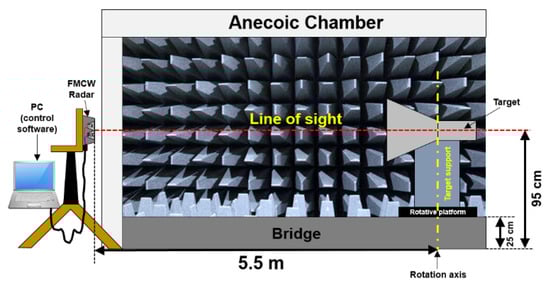
Figure 1.
Schematic view of the measurement setup.
The fundamentals of the measurement process are described below. A line of sight between the radar module and target was established. Then, the radar module was fixed and pointed to the target center, while the object was gradually rotated by a rotating platform. Therefore, the signal being scattered and received was saved and postprocessed when the target rotated one turn. In particular, the user interface of the commercial radar module Dk-sR-1200e provides the received power density Pr as a function of the measurement distance. The distance between the radar and the rotation axis of the target was 5.50 m, so the measurements were performed following near-field conditions as mentioned in the Introduction section. Then, once the received power density Pr was obtained and controlling the incident power density Pi provided by the radar, the measured RCS was extracted by applying Equation (2). However, the distance between the radar module and the metallic wall where the incident wave was scattered (distance near 5.50 m, depending on the rotation angle) needed to be taken into account in order to obtain an adequate Pr parameter at the corresponding distance and thus make proper calculation of the RCS parameter.
3. Monostatic RCS of Simple Targets in Near-Field Conditions to Calibrate the Measurement Setup
The measurement setup configuration was properly calibrated by measuring the RCS of two simple cases, namely, a metallic flat and a metallic box. As demonstrated in the state-of-the-art literature, a metallic sphere is usually used to calibrate the system [14,15,16]. It is known that this object provides a constant RCS value of πR2 in far-field conditions. However, the RCS response is unstable and presents fluctuations in near-field conditions as described in [21,22]. For this reason, a more precise calibration was performed using a metallic flat or a metallic box.
3.1. Metallic Flat
A metallic flat was determined as the simplest target to calibrate the measurement setup. Due to the size restrictions of the anechoic chamber, where the distance between the radar and target had been fixed to 5.50 m, the measurements were carried out in the near-field range. For this reason, a comparison between the measurements and the simulations was done following these conditions. Many works have discussed the prediction of far-field RCS from near-field results, such as [14,17]. Indeed, the newFASANT software allows easy calculation of RCS following near- and far-field conditions.
Figure 2 presents a comparison between the measured RCS of the metallic flat and the simulations extracted from newFASANT. Both the conventional MoM technique and the proposed GTD–PO methodology were applied. As shown in Figure 2, there was very good agreement between the MoM and GTD–PO results. Furthermore, the similarities between both simulation methods and the measurements were significant, especially around the broadside direction (θ = 0°), where the RCS curves showed the main lobe with a maximum level higher than +20 dBsm. Therefore, the data presented demonstrate that the measurement setup was correctly established, validating the measurement process as well as the experimental results.
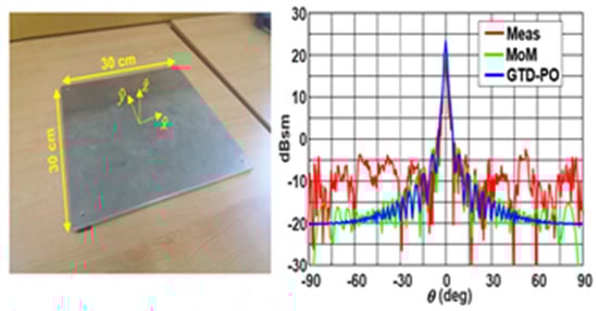
Figure 2.
Metallic flat (30 × 30 cm2). Monostatic radar cross section (RCS) results in near-field conditions (at 5.50 m): geometrical theory of diffraction–physical optics (GTD–PO) simulation, method of moments (MoM) simulation, and measurements.
3.2. Metallic Rectangular Box
An aluminum rectangular box of 30 × 12 × 75 cm3 was also measured in order to calibrate and validate the measurement setup. The box was set vertically, relying on one of its smaller faces.
As shown in Figure 3, where the monostatic RCS in the XY plane (θ = 90°) at near-field conditions is presented, a great similarity between the measured and simulated results was achieved. The RCS curves clearly showed four main lobes matching the four faces of the metallic box. Simulated results calculated by MoM and GTD–PO techniques also presented very good agreement between them, demonstrating that the RCS response was properly calculated using the proposed hybrid method. Maximum RCS values of about +20 dBsm were obtained in the broad walls of the metallic box (ϕ = 0° and ϕ = 180°), while RCS values around +15 dBsm were obtained in its narrow walls.
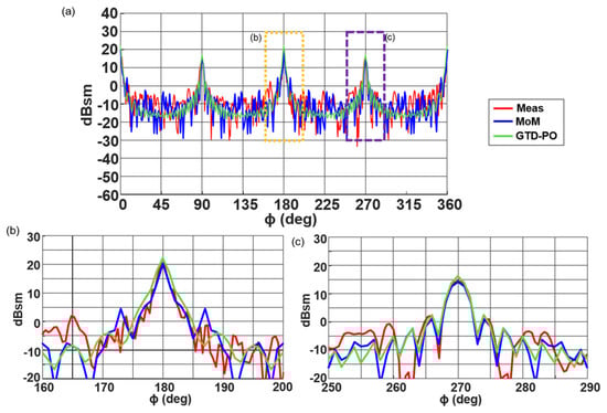
Figure 3.
Metallic box. (a) Monostatic RCS results in near-field conditions (at 5.50 m): GTD–PO simulation, MoM simulation, and measurements. Detail of the RCS in the broad wall (b) and the narrow wall (c) of the metallic box.
4. Monostatic RCS of Complex Targets in Near-Field Conditions
This section presents the evaluation of RCS for some complex targets, such as a cavity structure and an electromagnetic bandgap structure, using the MoM and GTD–PO methods, along with experimental measurements to validate the simulated results.
4.1. Cavity Structure
First, the monostatic RCS of a rectangular open-cavity structure was analyzed in near-field conditions. The object was a rectangular waveguide probe, where one side was opened and the other was shorted, with an internal aperture of 29 × 11 cm2, as shown in Figure 4. As in the previous cases, the distance between the radar module and the geometrical center of the rectangular waveguide was 5.50 m. Considering that the internal length of the waveguide was 70 cm, the distance between the radar module and the short-circuit placed at the back of the object was about 5.85 m.
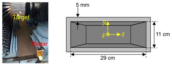
Figure 4.
Rectangular open-cavity structure and measurement setup.
A comparison between the measurements and MoM simulated results of the near-field RCS is presented in Figure 5. As expected, the maximum value was obtained at broadside direction (θ = 0°). In this case, the transmitted signal was directly reflected by the internal short-circuit of the rectangular waveguide and received by the radar module. However, when the open-cavity structure was analyzed for different incident angles (when the target started to rotate), the transmitted signal suffered multiple reflections and bounces. Therefore, the monostatic RCS response of the cavity structure showed several lobes around the broadside direction. Finally, a pair of maximum RCS values was achieved at θ = −90° and θ = +90° because the transmitted signal was totally reflected by the external sidewall of the structure (the signal did not penetrate into the cavity in this case). A comparison with results obtained using GTD–PO is not presented because, except for the main lobe, the GTD–PO results were not accurate enough for this deep cavity.
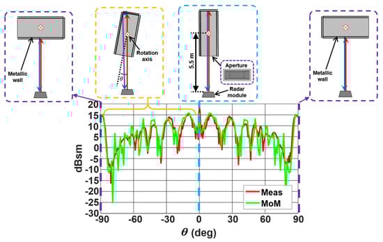
Figure 5.
Monostatic RCS results in near-field conditions (at 5.50 m) for a rectangular open-cavity structure (metallic waveguide): MoM simulation and measurements.
An acceptable similarity between simulations calculated by MoM and the measurements was observed, although some differences were found. The amplitude of the measured RCS in the broadside direction (θ = 0°) was slightly greater than the simulated responses. In the measurement process, the incident field on the target Ei was estimated by the FMCW radar at 5.85 m distance, taking into account the fact that the transmitted signal was reflected by the internal short circuit positioned at the back of the horn. However, in the simulations, the incident field on the target was computed at 5.85 m, where it was placed on the rotation axis in the measurements. This difference in the estimation of the incident field value, with the MoM estimation being greater, meant the measurement values were greater than the computations. Nevertheless, it is considered that the presented results show great concordance between them.
4.2. Metallic EBG Structure
The monostatic RCS of a double-stacked metallic grille structure was analyzed next. The detail of this prototype is shown in Figure 6a. It consisted of a 35.4 × 35.4 cm2 double metallic grille conformed by 24 × 24 equally spaced holes, which were positioned on top of a metallic flat ground at the distances shown in the figure. An EBG structure that follows a periodic pattern capable of cancelling specific electromagnetic waves depending on their frequency was used. It was designed for an antenna application at 9.8 GHz. However, in this work, we analyzed its RCS at 24 GHz.
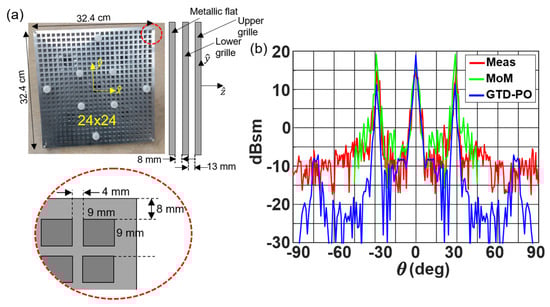
Figure 6.
Double metallic grille (electromagnetic bandgap (EBG) structure). Dimensions (a) and monostatic RCS results (b) in near-field conditions (at 5.50 m): GTD–PO simulation, MoM simulation, and measurements.
Figure 6b shows the experimental response of the near-field RCS compared to the RCS simulations calculated in newFASANT (MoM and GTD–PO). All the RCS curves showed three differentiated lobes. The one aiming at θ = 0° was caused by the direct reflection of the metallic flat ground that acted as a reflector, and the other pair of lobes aiming at θ = ±30° was generated by the presence of the double metallic grille. The main difference occurred in the maximum level of the two lobes produced by the metallic grille (at θ = ±30°). The main reason for these differences between MoM simulations and the measurements might be the resonance phenomena. The measurement of the FMCW radar module considered a distance greater than the 5.50 m between the radar and the target.
In addition, both the simulated and measured results of Figure 6b clearly showed the different behaviors of the RCS of a conventional metallic flat and the RCS of a double metallic grille. In order to experimentally compare both structures, the monostatic RCS of a simple metallic flat with similar dimensions to the metallic grille structure was also measured. The results for the near-field RCS of these structures in the angular range from θ = −90° to θ = +90° are shown in Figure 7. The double metallic grille structure showed a pair of lobes at θ = ±30°, which was not found in the simple metallic flat measurements. Taking into account the fact that the measurements were made under the same conditions (the metallic grille structure was first measured, and the metallic flat was then positioned on top of it), there is no doubt that the two side lobes were generated by the presence of the double metallic grille.
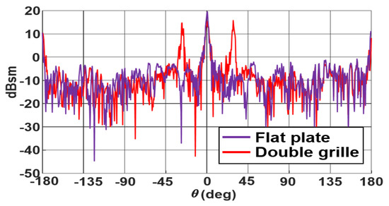
Figure 7.
Metallic grille and flat plate monostatic RCS results in near-field conditions (at 5.50 m): measurements.
5. Monostatic RCS of an Airplane in Near-Field Conditions
The monostatic RCS of an airplane mock-up was measured in near-field conditions. Figure 8 shows an image of the airplane, where the volume of the mock-up was about 2.10 × 1.70 × 0.80 m3 considering the wings of the plane. The shape of the airplane body was approximated as a cylinder with 25 cm diameter. This structure can be considered as quite similar to other curved, multifaceted, and complex targets typically found in traffic applications.
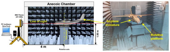
Figure 8.
Modified measurement setup for the airplane mock-up.
In order to analyze this structure using the software newFASANT, it was strictly necessary to create a 3D model of the structure. Therefore, a Creaform Academia 3D scanner was used to generate the mesh file of the geometry. After that, a postprocessing methodology was applied to transform the mesh geometry into a 3D model based on nonuniform rational B-spline (NURBS). The near-field RCS was then calculated using the MoM and GTD–PO techniques. In this particular case, the distance between the source (radar module) and the target (airplane mock-up) was reduced due to space limitations in the anechoic chamber. The measurement setup was slightly modified in this case, with the airplane positioned at 4 m distance and 1.50 m height, as shown in Figure 8.
The monostatic near-field RCS measurements as well as MoM and GTD–PO simulations are presented in Figure 9 (polar representation) for the azimuth plane of the mock-up. A good agreement between MoM and measurement curves was noticed. The main lobe, higher than 4 dBsm, was obtained at ϕ = 0° angular direction, identified as the front of the airplane mock-up. The sidewalls of the airplane also showed RCS levels higher than 0 dB (around ϕ = 90° and ϕ = 270°), while the numerical mean RCS value in the rest of the azimuth plane was around −10 dBsm. Results using GTD–PO were not as close to the measurements as the MoM results. However, a high correlation between the average values of GTD–PO and the measurements was noticed.
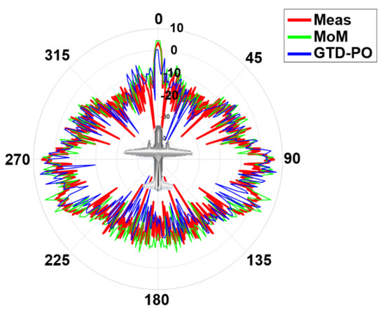
Figure 9.
Monostatic RCS results of the airplane mock-up in near-field conditions (polar representation): GTD–PO simulation, MoM simulation, and measurements.
In order to evaluate the strength of the proposed methodology, the required resources for both MoM and GTD–PO were evaluated and compared. Table 1 shows the time required by the GTD–PO and MoM methods to reach the solution, and it serves as validation of the efficiency of the GTD–PO method. The CPU times were obtained with a workstation with two Intel Xeon processors operating at 2.2 GHz with 128 GB RAM. As can be seen, the computation of the monostatic RCS of the airplane mock-up in near-field conditions using the GTD–PO method produced a gain of CPU time of 9.3 times with respect to that required by the MoM method. These results show that the GTD–PO method provides accurate results with low CPU time consumption.

Table 1.
Comparison of the CPU time and memory resources required for analysis of the monostatic RCS of the airplane mock-up in near-field conditions.
6. Human Body
To conclude the measurement process of complex targets, some measurements were made on the human body, more specifically, around the waist considering a vertical human body.
As shown in Figure 10, variable RCS level with a mean value of −6 dBsm was achieved. According to some sources, such as [23], the RCS level for a person at the radar operating frequency (24 GHz) varies between −6 dBsm and −4 dBsm. Therefore, these measurements can be considered valid.
Figure 10.
Human body: monostatic RCS results in near-field conditions.
7. Conclusions
RCS can be considered as an indispensable parameter to determine the detectability of an object. Therefore, RCS analysis of structures with diverse topologies is of great interest in the characterization of EM scattering problems in real scenarios. However, the RCS estimation of complex targets is usually difficult. This paper presents an efficient EM method in order to characterize a traffic scenario based on the combination of GTD and PO methodologies.
The great similarity between the proposed GTD–PO method and MoM demonstrates the good performance of this numerical method in order to characterize very complex structures. The computational cost is significantly reduced by applying the GTD–PO technique, with results that are accurate enough for most traffic applications. In order to experimentally validate the EM simulations, a simple system that uses a commercial vehicle radar to measure near-field RCS was employed. In particular, measurements of multiple complex structures were performed with a FMCW radar at 24 GHz. This work focused on the near-field range because most applications of these radars in traffic scenarios are in the near-field range. The measured RCS values obtained by the instrument in an anechoic chamber were compared with simulated values obtained by MoM and GTD–PO in the near-field range. An acceptable agreement between the simulations and the measurements was obtained.
Therefore, numerical methodologies like the GTD–PO hybrid technique appear suitable for estimating the monostatic RCS of complex targets of real scenarios with reasonable computational cost and ensuring acceptable concordance to the measurements. Experimental and numerical characterization of RCS in the near-field range can be very useful for the development and estimation of electromagnetic scattering problems in real traffic scenarios.
Author Contributions
Conceptualization, F.C.; methodology, F.C.; software, L.L. and Á.S.; validation, P.S.-O., L.L. and Á.S.; formal analysis, F.C., P.S.-O., and L.L.; writing—original draft preparation, P.S.-O., L.L., and F.C.; writing—review and editing, L.L. and F.C.; visualization, F.C.; supervision, F.C.; project administration, F.C.; funding acquisition, F.C. All authors have read and agreed to the published version of the manuscript.
Funding
This work was supported in part by the Spanish Ministry of Economy and Competitiveness, European Union (Project Ref. TEC 2017-89456-R and DI-14-06818), by the Junta de Comunidades de Castilla-La Mancha (Project Ref. SBPLY/17/180501/000433).
Conflicts of Interest
The authors declare no conflict of interest.
References
- Polka, L.; Birtcher, C.; Balanis, C. RCS measurements of plate geometries with theoretical verification. In Proceedings of the Antennas and Propagation Society Symposium 1991 Digest, Volondon, ON, Canada, 24–28 June 1991; pp. 1078–1081. [Google Scholar]
- Maamria, T.; Kimouche, H. Investigation of monostatic RCS measurement for simple and complex shapes at 9.4 GHz. In Proceedings of the 2015 4th International Conference on Electrical Engineering (ICEE), Boumerdes, Algeria, 13–15 December 2015; pp. 1–5. [Google Scholar]
- Borkar, V.; Ghosh, A.; Singh, R.; Chourasia, N. Radar Cross-section Measurement Techniques. Def. Sci. J. 2010, 60, 204–212. [Google Scholar] [CrossRef]
- Shen, X.-J.; Chen, X.; Zou, Y.-Q.; Zhang, Y.-M. Time-Domain Planar Near-Field Measurement Simulation for Wideband RCS and Antenna. In Proceedings of the 2007 IEEE Radar Conference, Boston, MA, USA, 17–20 April 2007; pp. 535–540. [Google Scholar]
- Dulucq, B.; Morvan, S.; Massaloux, P.; Mazé-Merceur, G. Near-field 3D-RCS measurement simulation: Antenna pattern issues. In Proceedings of the 8th European Conference on Antennas and Propagation (EuCAP 2014), Hague, The Netherlands, 6–11 April 2014; pp. 3225–3227. [Google Scholar]
- Massaloux, P.; Cartesi, G.; Lespiaux, D. Indoor RCS Measurement Facility ARCHE 3D: RCS Multi-Calibration under Spherical Wave. In Proceedings of the 2015 9th European Conference on Antennas and Propagation (EuCAP), Lisbon, Portugal, 12–17 April 2015; pp. 1–5. [Google Scholar]
- Knott, E.F. A progression of high-frequency RCS prediction techniques. Proc. IEEE 1985, 73, 252–264. [Google Scholar] [CrossRef]
- Bouche, D.; Molinet, F.; Mittra, R. Asymptotic and hybrid techniques for electromagnetic scattering. Proc. IEEE 1993, 81, 1658–1684. [Google Scholar] [CrossRef]
- Algar, M.J.; Lozano, L.; Moreno, J.; González, I.; Cátedra, F.; Morneo, J. An efficient hybrid technique in RCS predictions of complex targets at high frequencies. J. Comput. Phys. 2017, 345, 345–357. [Google Scholar] [CrossRef]
- Chew, W.C.; Jin, J.; Michielssen, E.; Song, J. (Eds.) Fast and Efficient Algorithms in Computational Electromagnetics; Artech House Incorporated: Norwood, MA, USA, 2001. [Google Scholar]
- Delgado, C.; Mittra, R.; Catedra, F. Accurate Representation of the Edge Behavior of Current When Using PO-Derived Characteristic Basis Functions. IEEE Antennas Wirel. Propag. Lett. 2008, 7, 43–45. [Google Scholar] [CrossRef]
- García, J.-L.; Somolinos, A.; Lozano, L.; González, I.; Cátedra, F. Hybrid Technique for Efficient and Accurate Analysis of the V2X Channel in Urban Traffic Scenarios. In Proceedings of the 12th European Conference on Antennas and Propagation (EuCAP), London, UK, 9–13 April 2018; pp. 1–4. [Google Scholar]
- NewFASANT: EM Simulation Software. IEEE Antennas Propag. Mag. 2013, 55, 181. [CrossRef]
- Chang, D.-C.; Tzay, M.-C.; Chung, R.-C. Far field RCS prediction by near field RCS measurement. In Proceedings of the APMC 2001, 2001 Asia-Pacific Microwave Conference (Cat. No.01TH8577), Taipei, Taiwan, 3–6 December 2001; Volume 3, pp. 1239–1242. [Google Scholar]
- Kent, B.M.; Chizever, H.M.; Soerens, R. On Reducing Primary Calibration Errors in Radar Cross Section Measurements. In Proceedings of the 18th Annual Symposium. Antenna Measurement Techniques Association, Seattle, WA, USA, 30 September–3 October 1996; pp. 383–388. [Google Scholar]
- Larsson, C.; Gustafsson, M.; Kristensson, G. Calibration Methods for Wideband forward RCS Measurements. In Proceedings of the Fourth European Conference on Antennas and Propagation, Barcelona, Spain, 12–16 April 2010; pp. 1–5. [Google Scholar]
- Falconer, D. Extrapolation of near-field RCS measurements to the far zone. IEEE Trans. Antennas Propag. 1988, 36, 822–829. [Google Scholar] [CrossRef]
- Knott, E.F.; Shaeffer, J.F.; Tuley, M.T. Radar Cross Section. Its Prediction, Measurement and Reduction; Artech House Incorporated: Dedham, MA, USA, 1985; Chapter 5. [Google Scholar]
- Ruck, G.T.; Barrick, D.E.; Stuart, W.D.; Krichbaum, C.K. Radar Cross Section Handbook; Plenum Press: New York, NY, USA, 1970; Volume 1, Chapter 2. [Google Scholar]
- Skolnik, M.I. Radar Handbook, 3rd ed.; McGraw Hill: New York, NY, USA, 2008. [Google Scholar]
- Bradley, C.J.; Collins, P.J.; Temple, M.A.; Terzuoli, A.J.; Nesti, G.; Fortuny, J.; Lewis, G.D. Issues in the Calibration of Bistatic RCS Measurements. In Proceedings of the Eleventh International Conference on Antennas and Propagation (IEE Conf. Publ. No. 480), Manchester, UK, 17–20 April 2001; Volume 1, pp. 293–297. [Google Scholar] [CrossRef]
- Shough, M.L. Radar Detection of Spherical Targets. NARCAP Research Associate (United Kingdom), 2009. Available online: http://www.martinshough.com/aerialphenomena/RCSsphere.pdf (accessed on 10 November 2020).
- Motomura, T.; Uchiyama, K.; Kajiwara, A. Measurement results of vehicular RCS characteristics for 79GHz millimeter band. In Proceedings of the 2018 IEEE Topical Conference on Wireless Sensors and Sensor Networks (WiSNet), Anaheim, CA, USA, 14–17 January 2018; pp. 103–106. [Google Scholar]
Publisher’s Note: MDPI stays neutral with regard to jurisdictional claims in published maps and institutional affiliations. |
© 2020 by the authors. Licensee MDPI, Basel, Switzerland. This article is an open access article distributed under the terms and conditions of the Creative Commons Attribution (CC BY) license (http://creativecommons.org/licenses/by/4.0/).