1. Introduction
Utilizing optical fiber transmission links (OFTL) for long distance communication with a huge amount of data is mostly affected by the nonlinear impairments (NLIs) due to the channel and linear distortions (LDs) due to the system components [
1,
2]. Apart from limiting the maximum data rate that can be transmitted through the system, such effects are bottleneck to the long-haul transmission distances. Although fronthaul networks are limited to transmission distances up to 20 km, the use of high bandwidth signals or intermediate frequency (IF) is still a question in the presence of such impairments [
3]. Due to the capacity issues with the current CPRI transport, RoF can provide a promising solution for the integration of radio signals and OFTL as a significant procedure for high capacity and cost effective transmissions [
4,
5,
6]. This transport scheme is a worthy suspension for huge capacity wireless transmission by virtue of low cost, due to its uncomplicated model and anti interference huge bandwidth, low medium distortion and low power consumption [
7]. Furthermore, mobile communication adaptability and flexibility to associate with the growth of the overall network [
8]. The mobile network industry has been ruled by the digital transmission of data over the optical fiber network for a long time in fourth generation (4G) long term evolution (LTE) systems due to its robustness to the nonlinear impairments and resistance towards the chromatic dispersion effects. The transportation of baseband data in CPRI to the remote antenna unit (RAU) requires the use of a digital to analog converter (DAC) to generate an analog waveform, which is further upconverted to the desired radio frequency (RF). The use of RoF transport not only lowers the cost of the RAU by avoiding the use of DACs, but it also requires low sampling rates to transport huge bandwidth signals. For example, the release 15 of third generation project partnership (3GPP) for the 5G networks suggest that the bit rate transport requirement for CPRI is around 159 Gb/s for a 40 MHz bandwidth signal with 8 MIMO layers and 32 antenna elements at the RAU with three sectors. The same amount of transportation using RoF technology requires much lower data rates and thus can be considered as a potential candidate for the future 5G networks. Developing RoF systems with wavelength division multiplexing (WDM) technology has the potential to increase the fidelity by many folds with addition of advance modulation formats such as 64-quadrature amplitude modulation (QAM) using orthogonal frequency division multiplexing (OFDM) signals, thus intending to enhance the propagation path and data rate capacity [
9,
10]. This paper investigates a WDM-based RoF transport system with an aim to suppress the NLIs and LDS.
The improved long range and high capacity RoF network depends upon how best the LDs and NLIs are managed. In this model, single model fiber (SMF) is used as a backbone to transmit the RF wave, includes LDs like group velocity dispersion (GVD), polarization mode dispersion (PMD) and amplified spontaneous emission (ASE). The shape of the pulse is distorted due to these LDs. In this paper, LDs are addressed, narrowing the pulse width with the help of employing advance modulation schemes and installing filters and amplifiers.
1.1. Related Work
To develop the communication network resistance against the advanced NLIs and LDs, the use of equalizers in RoF technology is considered as a general solution but the industry demands for an ultra-reliable network from the 5G mobile systems, if RoF transport is utilized as a fronthaul network. This area has huge potential for research due to several advantages of RoF transport, in order to design the optimized structure and be able to support current demands of capacity with overcoming NLIs and LDs. Some of the recent work in this domain is discussed as follow.
RoF transport has been explored recently for the transmission of millimeter-wave signals for 5G system [
11]. In [
12], authors have studied an adaptive RoF system for the next generation C-RAN, with the goal to compensate NLIs. A 2 × 2 multiple input multiple output (MIMO) with OFDM waveform is explored in [
13] for the intermixing noise of signals after the RoF transport. A WDM-RoF network is analyzed in [
14], keeping 0.4 nm channel spacing and fixed input power while focusing transmission of data streams over a range of optical fiber lengths. In [
15], RoF transmission system is discussed by authors with multimode operation to transport multi wavelength optical comb signals. The inter-modal noise for such systems is the same for RoF transmission as its digital counterpart for the 4QAM-OFDM-based signal transmission. In [
16], authors have analyzed D-band millimeter wave generation and propagation scheme employing cascaded intensity modulator and in-pulse quadrature modulators (QMs). These two modulators operate on optical carrier by suppressing the main mode to generate two pairs of dual single-sideband signals. A multi service digital RoF system for a neutral host fronthaul link is presented in [
17] based on the multiband multiplexing. In [
18], authors have demonstrated an RoF transmission system in S-band using a 2 × 2 multiple input multiple output (MIMO)-OFDM with orthogonal and bi orthogonal wavelets. Optimization of signal processing schemes for downlink and uplink of a C-RAN architecture is studied in [
19], which serves wireless link users with nonlinear energy harvesting (EH). Similarly, in [
20], the authors have described a full duplex RoF system in terms of integrated silicon ring modulator using coherent dual wavelength closer source. However, the drawbacks like side-lobes with high power levels, low spectral efficiency, high cost and complex structure make space for alternative options in the WDM-RoF system. Other recently reported RoF demonstrations include millimeter-wave transmission supported ultrahigh speed transmission [
21] by making use of the direct photonic upconversion to generate millimeter-waves at the remote antenna unit [
22]. A comparison of RoF transport has been made in [
23] with free-space optics setup for QAM modulated data transmission using SMF of the order of 50 km [
24]. Thus, this paper proposes an optimized design of the WDM-RoF system with advance modulation formats to overcome the NLIs and PAPR issues.
1.2. Major Contributions
It is a fact that a RoF transmission link transporting a very large number of user signals at high data rates suffers badly from the NLIs and LDs. Thus, in this paper, a novel WDM-RoF-based system is developed, aiming to enhance the performance of the overall system and to support current high capacity demands. The basic goal was to reduce NLI, LD and PAPR issues and to achieve an optimize structure. The major contributions of this paper are documented as follows:
Optical transmission up to long range distances accumulates high order NLIs and LDs in a WDM-RoF network, but is still required to address the high capacity transportation demand of the future mobile networks. In this work, such effects are studied in detail with an analytical model and a solution is presented to compensate them for a high data rate WDM system.
System parameters like input launch power, received power and length of the transmission fiber are used to explore the effectiveness of the proposed model.
BER parameter is used to compute the fidelity of the proposed WDM-RoF proposed model and results are presented for various scenarios and conditions to explore the effectiveness of the proposed receiver.
Analytical approach is presented for the proposed WDM-RoF model and simulation work is carried out using realistic values of RF and optical components, suggesting 1 km to 10 km of transmission range. A −40 dBm to −15 dBm received power sensitivity and −20 dBm to 0 dBm input power are required to achieve multi Gb/s transmission and support high order modulation formats.
The remainder of this work is arranged as follows.
Section 2 presents the proposed system model layout, followed by the description of analytical model in
Section 3.
Section 4 summarizes the results and discussion of the presented system. Finally, the conclusion is presented in
Section 5.
2. Proposed Model Layout
The main objective of this paper is to present a distortion-tolerant WDM-based RoF link, employing advanced modulation formats such as 16 and 64-QAM OFDM for different transmission distances (1 km to 10 km length of fiber), high receiver sensitivity and low input power requirements. This is accomplished by management of NLIs, LDs and PAPR at different stages to ensure optimized performance for the proposed layout. The internal structure of the presented framework is explained in this section. The detailed framework of the proposed RoF system using WDM system is explained in
Figure 1a, declaring how RF signals are propagated over the OFTL. The main feature of the WDM-based RoF transmission system is the low cost system by avoiding the need of high frequency LO for upconversion of baseband signal to the desired RF frequency, analogue to digital conversion (ADC) at the central unit or digital to analogue conversion (DAC) at the remote antenna unit. The simulation model is built in Optisystem software which is a well-known simulation tool for analysis of optical fiber communication systems. Optisystem provides a considerable amount of library elements to model the RF and optical components according to the realistic values and characteristics. The RF signals are generated at the central unit in both OFDM and non-OFDM formats to investigate the performance of the two schemes. The signals is amplified and a directly modulated laser (DML) is installed at the output pin of the amplifier, aiming to convert the electrical signal into optical domain [
25]. The DML module helps in specifying different parameters for the laser like linewidth, adiabatic and transient chirp, side mode, suppression ratio and relative intensity noise (RIN) [
26]. Moreover, RIN and chirp characteristics of the DML model are taken from a commercial low-cost DFB laser to provide a realistic approach. The RIN is set to be −130 dB/Hz and chirp parameters, linewidth enhancement factor (
) and adiabatic chirp coefficient (k) are set to be 2.0 and
Ws
−1, respectively. For the WDM system, a number of such optical signals from different users are multiplexed with the help of a WDM-MUX module, where all channels are transported over a single mode fiber (SMF) link and the propagation loss and insertion loss of WDM module is compensated by using an erbium doped fiber amplifier (EDFA). At the RAU, a WDM-deMUX is used in the form of a fiber Bragg grating (FBG). FBG also helps to eliminated some portion of the amplified spontaneous emission (ASE) due to the filtering operation. To perform the O/E procedure, a PIN photodiode is installed at the output of the FBG which directly converts the optical signal to RF frequency due to the RoF transport. As a result, the RF signal received at the Rx is recovered at the desired radio frequency, where then it can be transmitted in to the free space. To further remove the out-of-band noise, a bandpass filter (or low pass filter with large bandwidth) is implemented before passing the RF signal to the QAM sequence decoder. The FDE block is connected at output of QAM, aiming to mitigate LDs and NLIs further. The internal parameters of FDE are presented in
Figure 1b. However, FDE alone is not sufficient to compensate the NLIs and PAPR. FDE outcomes are further purified from NLIS NLIs and PAPR using full field digital back propagation (DBP), decision directed least mean square (DD-LMS) and carrier phase estimation (CPE). Afterwards, to analyze and measure the quality of the received signals, the Optisystem software offers a BER analyzer tool which takes re-amplified, reshaped and re-timed form of the signal as an input from 3R-regenerator module. The custom design of the equalizer is explained in analytical modeling section to show that the proposed system provides high tolerance to the nonlinear effects and distortions. The experimental work of the proposed model is not available in laboratory due to high cost of devices; however, the analytical approach of the proposed model is investigated with realistic values of the modules and data transmission link, using Optisystem simulation model, which is considered as powerful tool for optical fiber transmission systems analysis. Optisystem provides a large set of optical and RF components library to form a complete downlink and uplink transmission system. It also provides a high level of integration with MATLAB for signal processing and implementation of custom based equalizers for the receiver side.
Table 1 lists the names of elements with their notations and magnitudes, which are applied for analyzing the WDM-RoF model and minimizing the impact of PAPR, NLIs and LDs. The values used in this setup have been taken from the recent field trials and experimental work to present a realistic analysis.
3. Analytical Modeling
The proposed WDM-RoF framework is discussed in
Section 2 in detail, while this section elaborates the mathematical model of the proposed solution, to present the performance against PAPR and AWGN noises in the electrical domain, and NLIs and LDs in the optical domain. Furthermore, the mathematical modeling of the proposed model is studied in three portions: the mechanism of process in terms of transmitting information, the issues like NLIs, LDs and PAPR and, finally, evaluation and solution of the problems. Each portion of the analytical model contains an individual mathematical procedure which is analyzed as follows. The RF signals from BSs are achieved by the transmitter, ‘Tx’, of OFTL [
27,
28] and can be computed as
where
represents the number of RF received pulses and
k explains the length of sequence of the attained pulses. The received
pulses are then modulated to QAM format, which splits the waves into two cascaded sequences. Each sequence can be transmitted with varying their amplitude
[
29,
30] and is calculated as
In Equation (
2), the
M denotes number of possible sequences of pulses and is defined as
where
i denotes the number of bits per symbol and M represents the QAM level. The sequence of pulses at QAM output ports are subdivided into two cascaded sequences. The multilevel pulses are generated using M-ary pulse generator in terms of input signals, which are measured as [
31,
32,
33,
34]
where
shows input signals of M-ary pulse generator,
b denotes linear gain, bias parameter s defined by
a,
T presents bit period,
use for duty cycle and
is the pulse position. The waves explained in Equation (
4) are interfered by QM in which output [
35] is given as
where
I and
Q are the input of electrical signals, gain of parameter is presented by
D, carrier frequency and phase are denoted by
and
. The QAM symbols are passed through a FFT module with size of 512 to obtain the OFDM signal. As OFDM signals suffer from high PAPR values, the following analysis is performed. In order to calculate the PAPR in electrical form of signals, consider QAM transmission with
n sub-carriers with frequencies (
). The continuous time signal
based on modulation interval
T and
duration of QAM symbols is defined as
The parameter
explains the expectation function. The gain of electrical amplifier which suppresses the high PAPR [
36,
37,
38] is measured as
The outcomes of Equation (
7) are measured in
, which gives the amplified electrical signals and is presented as
In the presence of PAPR induced distortions, the NLI and LD power spectral density (PSD) function is calculated as
where
means the noise power and
denotes the frequency grid spacing which is defined as
In order to transmit the RF signals over OFTL, the laser source is modeled as a low-cost DML. The electric field intensity of DML is defined as
From Equation (
1) to Equation (
10), the cosine of RF signal
is calculated as
where
shows the driving voltage of RF. The optical field at output of intensity modulation (IM) is given as
where
is the DC bias voltage and
explains the IM half wave voltage. Assume
and
, which explain the modulation index and initial phase caused by
of the IM, respectively. From Equation (
13), the
can be extended as
Here,
means the
ith order of Bessel function. The transfer function of the transmitted signal is measured as
where
is written as
Here,
denotes insertion loss,
means roll of factor and
,
are calculated as
Measurements of the NLIs and LDs in the propagation of light wave in fiber are given below:
where
A represents complex terms of electromagnetic field,
t represents time,
z denotes distance of fiber, for group velocity dispersion (GVD),
is used which is also known as linear dispersion;
is the nonlinear dispersion parameter, attenuation is represented by
and
is used for nonlinear coefficient. The relation among nonlinear refractive index
, carrier wavelength
and
is given by
The parameters which affect the amount of NLIs and LDs are cross-section area of SMF, amount of light intensity propagating through the fiber, number of channels in the WDM system and data rate. These factors generate an-harmonic motions of photons inside the SMF [
31], where the behavior of induced polarization
is no longer linear, which is given as
Here,
describes free space permittivity,
E means electrical field intensity and
,
and
determine first, second and third order susceptibility, respectively. The general power consumption of optical transmitter, ‘Tx’, is calculated as
where
denotes power conversion efficiency,
is the signal mapping of power consumption,
means power consumption due to QM,
explains M-ary power consumption,
shows the power consumption by reason of QAM,
means the quantity of MZMs required for WDM-RoF transmission. Similarly, the power consumption at the Rx side is measured as
The parameters
,
,
,
,
and
define the power consumption because of FBG, PD, QM encoder, M-ary pulse generator, amplification and QAM demodulator. The attained signal is explained as
where
is the amplitude of the received signal and
is amplitude of the transmitted signal. Furthermore, the sequence of recovered signal with compensated NLIs, LDs and PAPR is determined as
In Equation (
25), factor of power noise is described by ∀. The BER is used for the analysis of NLIs, LDs and PAPR parameters. If these issues exist then how many bit can be transferred including low error size per bit [
9]? BER is given as
where
N denotes symbols for estimating error vector magnitude (EVM),
is the vector of received signal,
is the transmitted vector signal,
is the average transmitted power of the used modulation. In Equation (
26), the complimentary error function (erfc) is used for the evaluation of probability functions that involve a Gaussian process. Moreover, parameter G denotes the QAM level.
These equations are employed for the analyzing the properties of the proposed model and how the WDM-RoF generates its outcomes. The upcoming section includes the simulation results based on the analytical model using a modified version of the equalizer presented in [
38].
4. Results and Discussion
The analytical model in
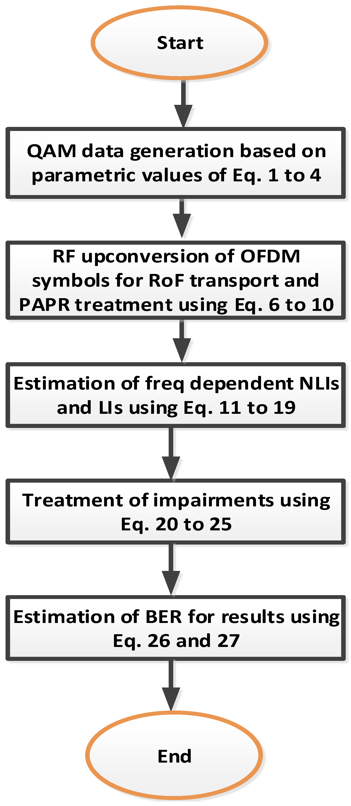
Section 3 presents how NLIs, LDs and PAPR interrupt the continuity of the WDM-RoF system and mitigate using the proposed system. Moreover,
Figure 2 explains the flowchart to show the link among analytical and simulation models. Furthermore, the management approach of NLIs, LDs and PAPR in the proposed model is explored for a different set of parameters. The impacts of NLIs, LDs, phase error (PE) and PAPR are analyzed in
Figure 3,
Figure 4,
Figure 5,
Figure 6,
Figure 7,
Figure 8 and
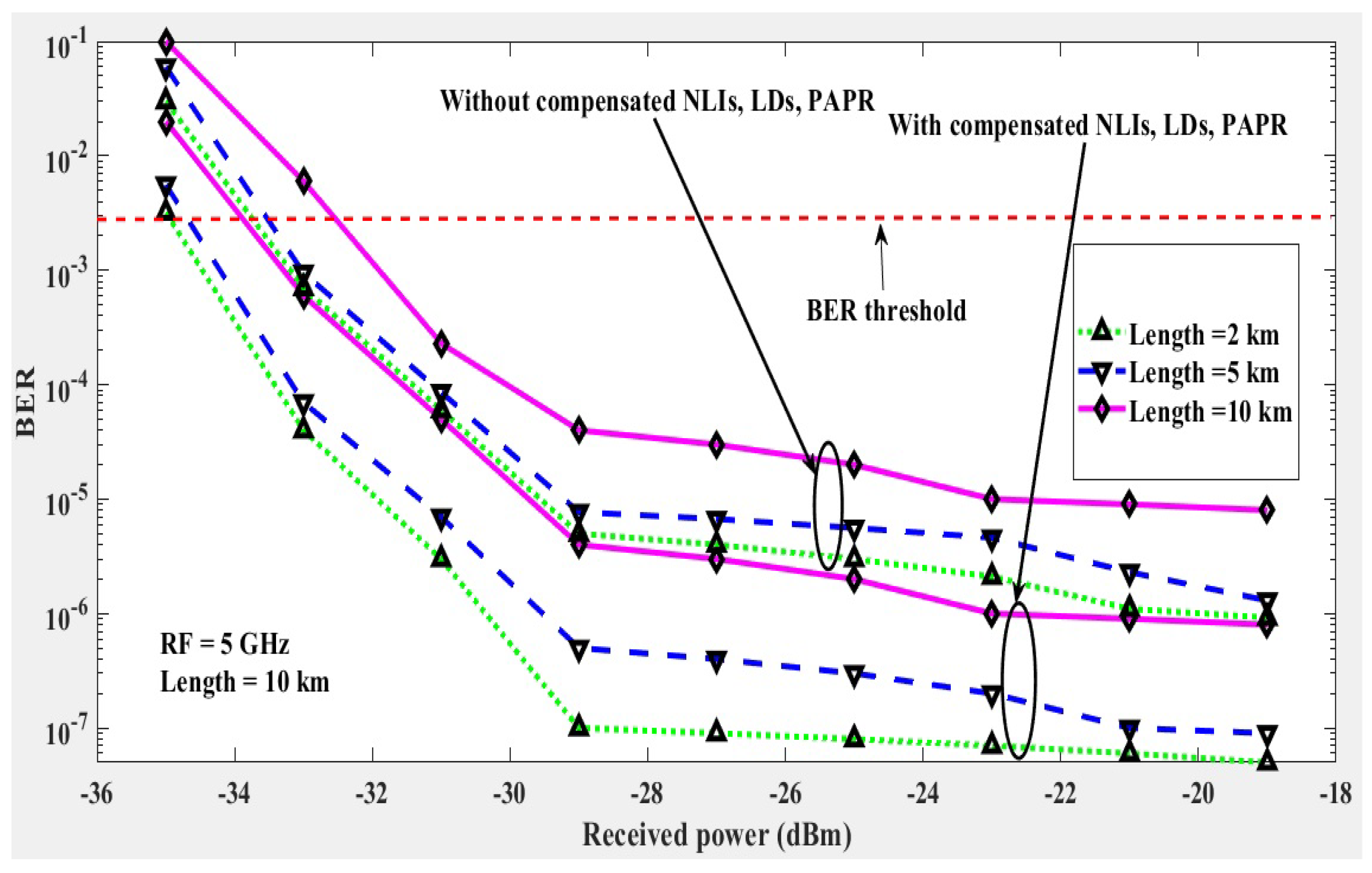
Figure 9, using simulation analysis with help of Equations (19), (21) and (25). Similarly, Equations (1) to (18), (22) to (24) and (26) to (28) are utilized for simulating the results in terms of received power, input power, transmission length, normalized signal to noise ratio and RF waves as a function of BER. To investigate the receiver’s sensitivity against the received optical power, a variable attenuator is used to provide a range of received power from −40 dBm to −20 dBm, measured using an optical power meter (OPM).
Figure 3 shows the relation of the received power and BER when transmission fiber length is varied up to 10 km. At received power levels below −34 dBm, the results are recorded to be above the considered BER threshold value of 3.8 ×
. Moreover, it is clear from
Figure 3 that the amount of NLIs, LDs and PAPR increases with the transmission distance. For a general system affected from NLIs and LDs, the results show that below
BER is achieved at −22 dBm received power for 10 km of fiber transmission length using 5 GHz RF signal, respectively. With the proposed solution, the same BER can be achieved with −30 dBm received power thus avoiding the 8 dB penalty caused by the distortion effects.
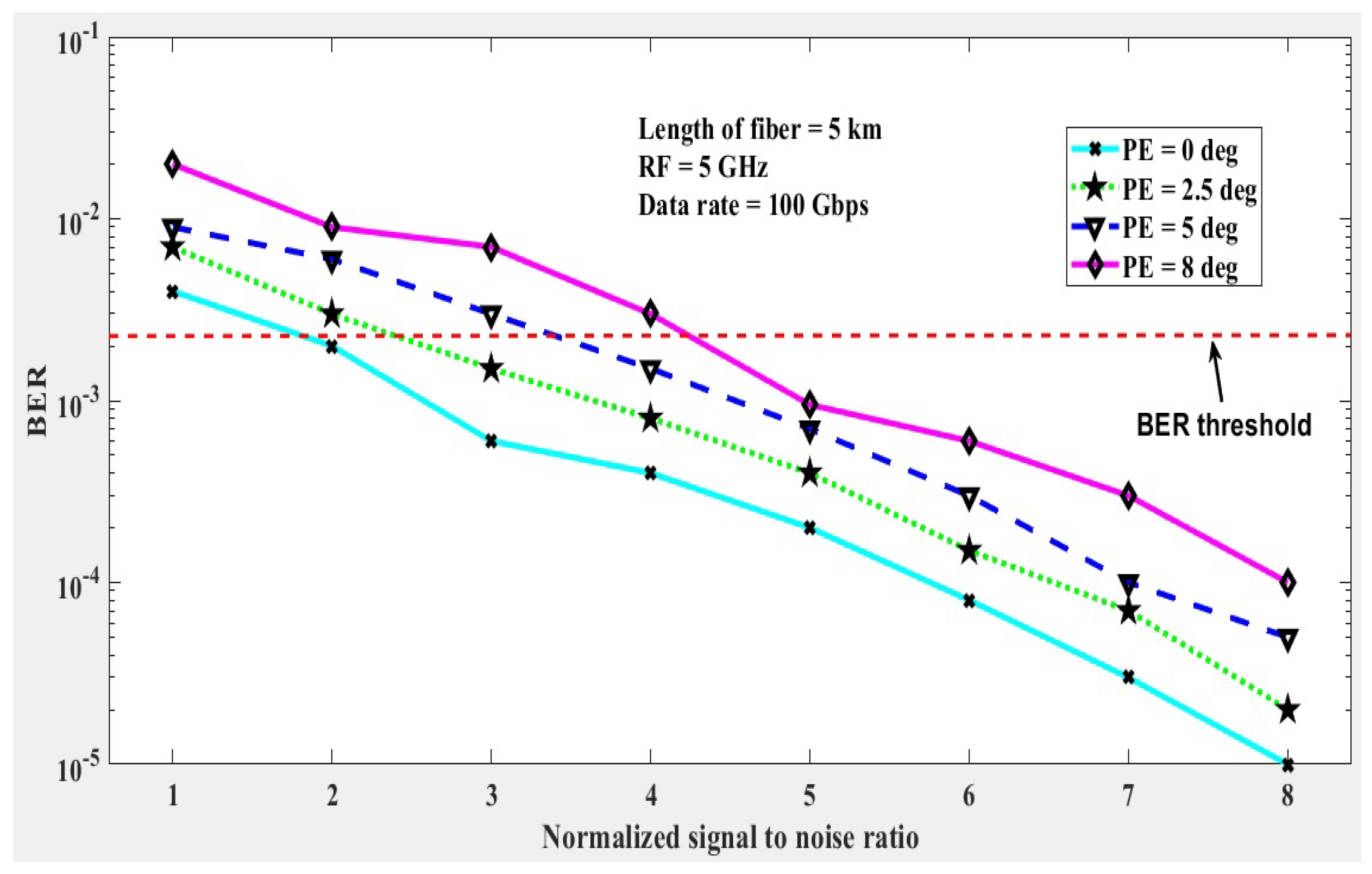
It is already discussed in the mathematical model that due to NLIs, LDs and PAPR, the transmission pulses experience phase errors (PEs).
Figure 4 shows the results for 0, 2.5, 5 and 8 deg PEs in terms of normalized signal to noise ratio on the x-axis. The simulation results in
Figure 4 for fiber length of 5 km show that PE affects the system performance, even with the treatment of NLIs and LDs. Considering a maximum 8 deg PE, the BER threshold requires very high SNR as compared to the lower values of the PEs.
Figure 5 represents the results of the presented model at 10 km transmission length for the impact of PEs which are induced due to NLIs and LDs. The results show that phase variations extend with the transmission distance but the proposed receiver can tolerate PE of 8.0 up to 10 km of transmission distance.The proposed WDM-RoF model is analyzed using different variations of the advanced modulation formats such as non-OFDM signals with 16QAM, 64QAM modulation and then 16QAM-OFDM and 64QAM-OFDM.
Figure 7 explains the results for the considered modulation formats when the transmission distance is increased up to 10 km. The improvement in performance can be observed with the use of OFDM modulation with PAPR treatment, which is not possible with high PAPR which causes saturation of the EA and supports NLIs.
Figure 8 shows the BER results with respect to the input launch power into the optical fiber for a 16-QAM OFDM signal with 50 GHz channel spacing. After 10 km of optical fiber transmission, the performance improvement with the proposed treatment of NLIs, LDs and PAPR is shown as compared to the general transmission case. The performance improvement saturates around −10 dBm because nonlinearities increase to a large extent afterwards as a result of the high launch power.
Figure 9 depicts the behavior of NLI, LDs and PAPR for the proposed WDM model and the BER outcomes with the increase in number of WDM channels. As the number of channels are increased, the crosstalk due to inter-channel interference affects the performance for smaller channel spacings. Such effects become more visible after transmission of 10 km of fiber distance as shown in
Figure 9. In addition, with decrease in channel spacing, the BER threshold cannot be achieved with 12.5 GHz spacing using 14 or more channels even with the treatment of NLIs and LDs.
The presented model is further investigated using constellation visualizer diagrams, optical spectrum analyzer and RF spectrum analyzer, which are explained in
Figure 10a–d,
Figure 11a–c and
Figure 12a–c.
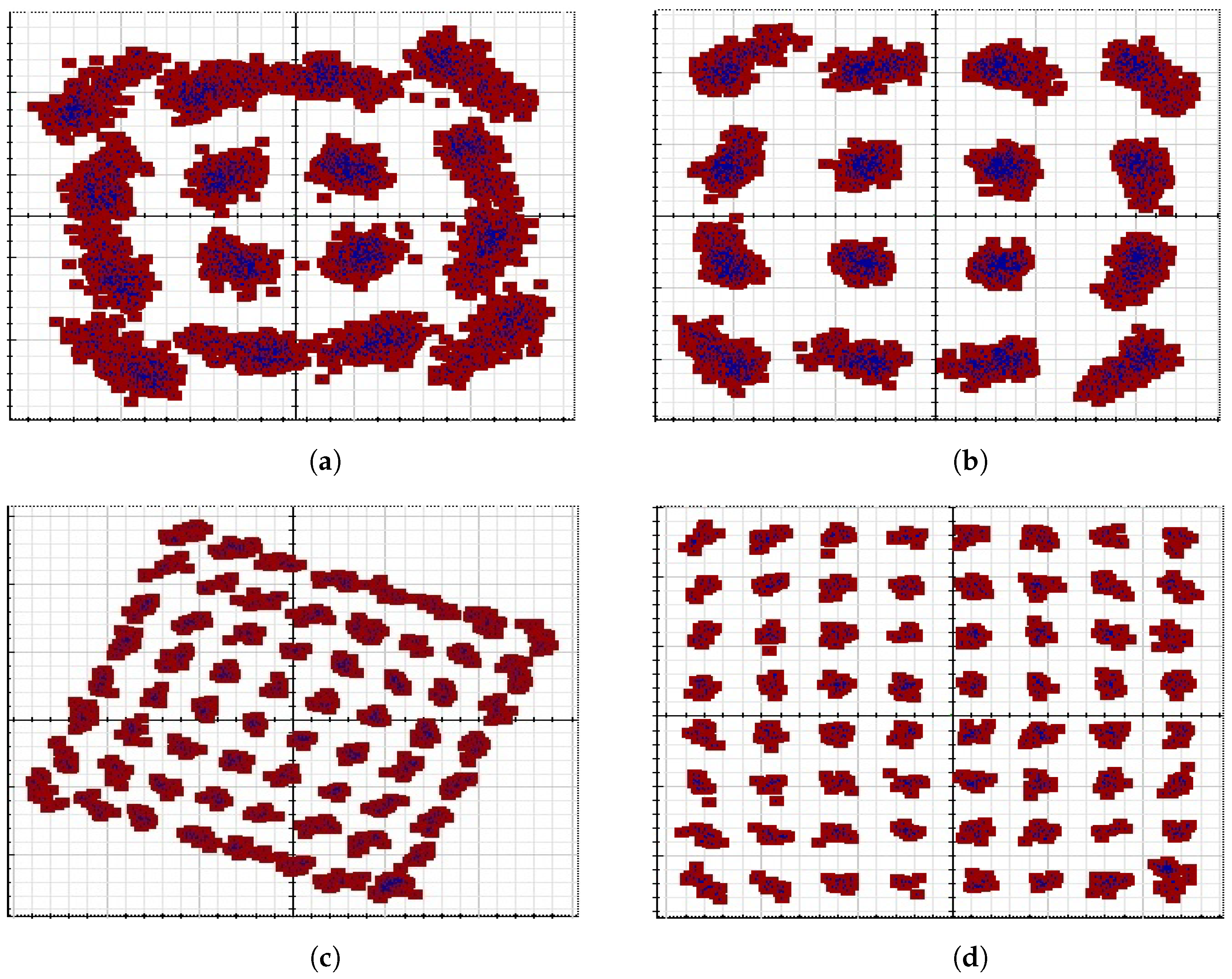
Figure 10a shows the performance of WDM-RoF model at 10 km of transmission range without mitigating NLIs, LDs and PAPR. The constellation diagram shows that received symbols are difficult to be recovered with such performance.
Figure 10b shows the performance improvement in terms of the recovered constellation for 16-QAM and
Figure 10d for 64-QAM.
Figure 11 shows the optical spectrum of the first channel from the WDM system. The optical spectrum shown in
Figure 11b has been taken from the output of the FBG at the RAU. The noise level can be seen due to the NLIs and LDs in green color, which spreads across the whole band. The proposed mitigation lowers it down to a considerable extent as can be seen from
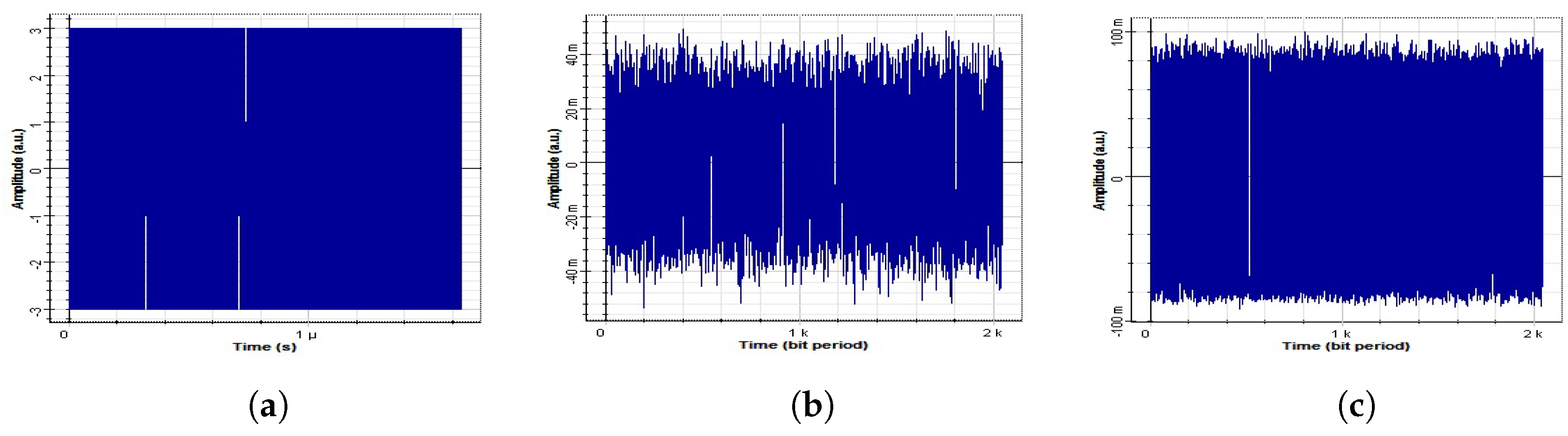
Figure 11c. The RF spectrum is shown in
Figure 12 where it can be seen how NLIs and DLs cause the amplitude variations (
Figure 12b) and are treated (
Figure 12c).

 ,
, 


