1. Introduction
The advantages of a lithium-ion battery are its high-energy density, low self-discharge rate, cycling durability, and wide temperature range [
1]. Due to its excellent performance, lithium-ion battery has become the best choice for electric vehicles and other energy storage systems. Due to the differences in the manufacturing and operating environment, inconsistency between the different batteries in the same battery group is existed [
2]. The inconsistency brings about a loss of capacity of the battery group, and it eventually leads to shorter battery life. A statistic shows that the capacity difference in different batteries of the same model can reach 20% [
3], bcause the capacity loss of one battery group can reach 40%. As time goes on, the inconsistency of batteries will increase. Battery equalizing is an effective way to reduce the battery decay rate in battery management systems (BMSs). Battery equalizing mainly focuses on the investigation of equalization topology and control algorithms [
4,
5,
6].
The battery equalizing technology plays a vital role in the performance improvement for lithium-ion batteries. Nowadays, there are two main battery-balancing methods: passive equalizing and active equalizing [
7,
8,
9,
10]. The passive equalizing method is that the energy of higher-power batteries is dissipated by one simple resistive circuit, and the energy is wasted in passive equalizing [
11,
12,
13,
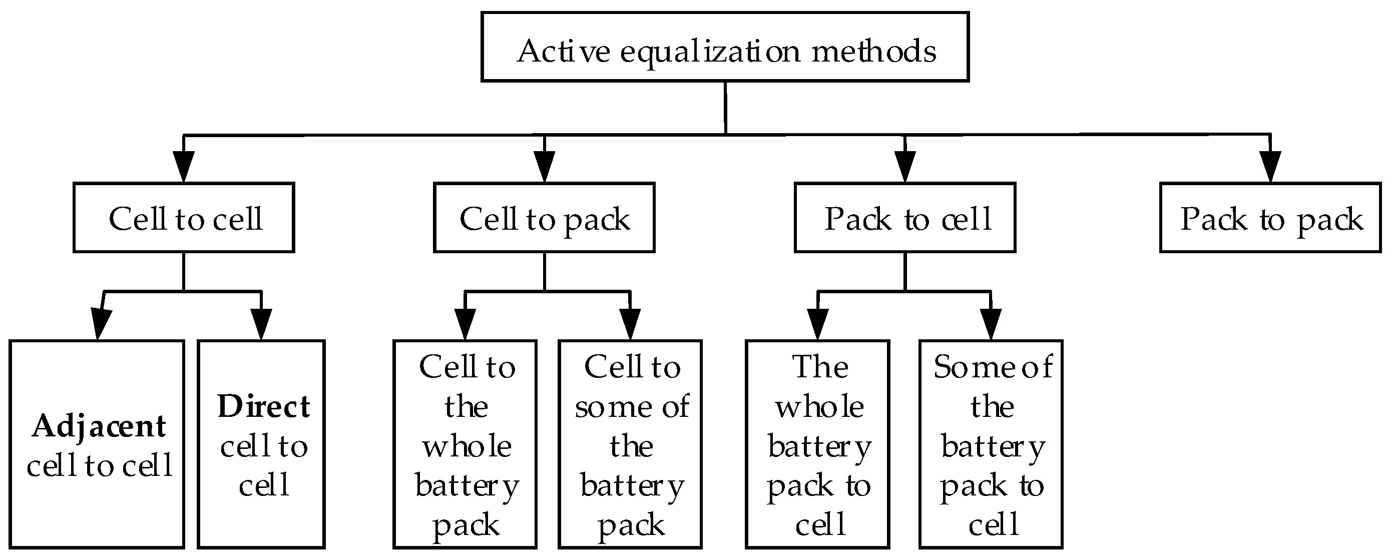
14]. Active equalizing mainly realizes the non-dissipative transfer of energy in the battery group through energy storage components. The main active equalization methods are shown in
Figure 1 [
1]. In traditional active equalization, the topology usually adopts a single equalization method. One active equalizing method that one cell transfers energy to adjacent cells step by step, thus the equalizing speed is very slow. Another active equalizing method is that the energy is transferred between the battery cell and the battery group [
15,
16,
17,
18]. However, it has a disadvantage of repeated energy transfer. All of these active equalizing methods have significant limitations in their equalization speed and equalization efficiency. The equalization topology regularly adopts the Flyback converter or the Forward converter [
19]. In these two topologies, a large amount of MOSFETs swiches are turned on or off at the same time, which may increase cost and reduce reliability. It is evident that using a single active or passive equalizing topology cannot meet actual needs [
20,
21]. For these reasons, a hybrid equalization topology is proposed in this paper. By combining multi-layer active equalization with passive equalization, the energy equalization of the battery group can be realized in different situations. The paper mainly includes the principle of the hybrid equalization topology, equalization efficiency analysis/calculation, experimental verification and conclusion [
22]
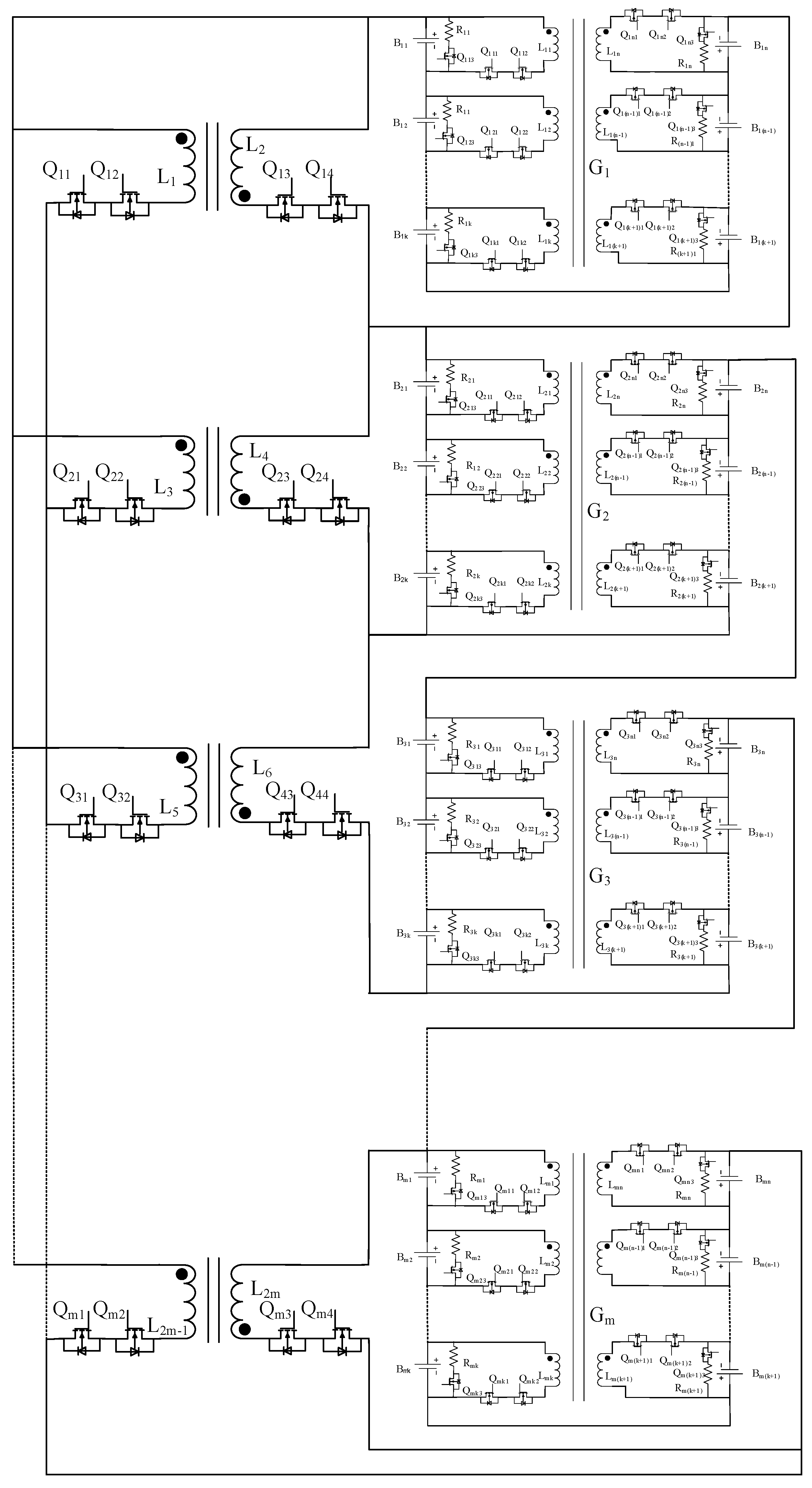
Figure 2 shows the system architecture of the proposed battery equalization topology. The topology contains the bidirectional forward and bidirectional flyback converters. The structure can be divided into two layers, the top layer is the between-group equalization, and the bottom layer is the in-group equalization. There are m × n battery cells in the system, each n cells forming one battery group, with m groups in total. So, the sub-circuits between the battery groups constitute the between-group equalization system, and the sub-circuits internal to the battery group form the between-group equalization system.
The in-group equalization system is composed of active and passive equalization. The active equalization sub-circuit consists of two reverse-series MOSFETs, a winding of the transformer, an auxiliary MOSFET, and a capacitor. The equalization sub-circuits of different batteries are connected by a multi-winding transformer. The turns ratio of the transformer is 1:1:1:1. The MOSFET interconnected to the battery can replace the diode of the traditional Flyback converter or the Forward converter. In addition, the conduction loss of the MOSFET is much less than that of the diode in the traditional converter topology. The passive equalization sub-circuit of each battery includes a MOSFET and a dissipative resistor. The energy of the higher-capacity cell can be released through the dissipative resistor by changing the switching states of the MOSFET.
The between-group equalization is adopted on the bi-drectional Flyback converter. Each battery group in this layer can charge to any battery cell with higher voltage and larger capacity, and the Flyback converter and the battery group are connected one to one. The primary side of the equalizer is the corresponding battery group, and the secondary side is the entire power supply system. The between-group equalization can realize bidirectional energy flow between the battery group and the entire power supply system.
This topology is a double-layer hybrid topology. It adopts an equalization strategy which combines active and passive balancing to improve the balancing efficiency. In addition, because of the double-layer design, it can be used in scenarios where the number of cells is large, and different layers can be balanced at the same time, which significantly reduces the time required for equalization. The bidirectional flyback converter can complete the energy equalization at a higher power level. The active equalization sub-circuit in each group can flexibly realize the energy exchange between cells. Besides, it is supplemented by a passive equalization circuit. The passive equalization method was used as when the voltage difference between battery cells is small, it can accelerate equalization. Specifically, there are four equalization modes (containing three in-group equalization modes and one between-group equalization circuit mode). The corresponding mode description is introduced below.
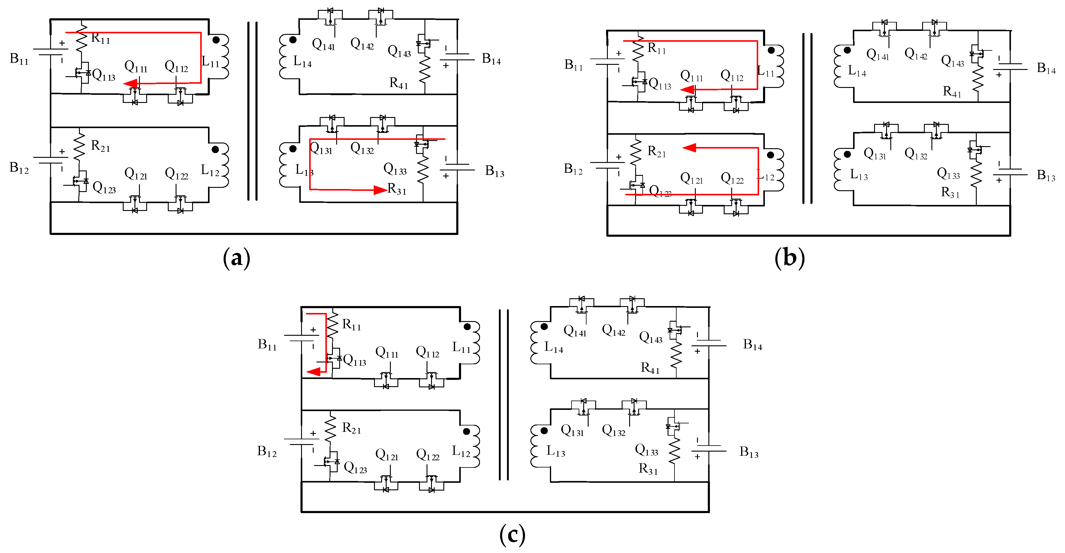
In the schematic diagram of in-group equalization in each group, taking four cells as an example, the cells are divided into two sides, B11 and B12 are on the left side, and B13 and B14 are on the right side. According to the position where the target battery and the source battery are located, the battery balancing topology proposed in this paper contains three in-group balancing modes and one between-group balancing mode.
1.1. MODE 1: In-Group Flyback Mode
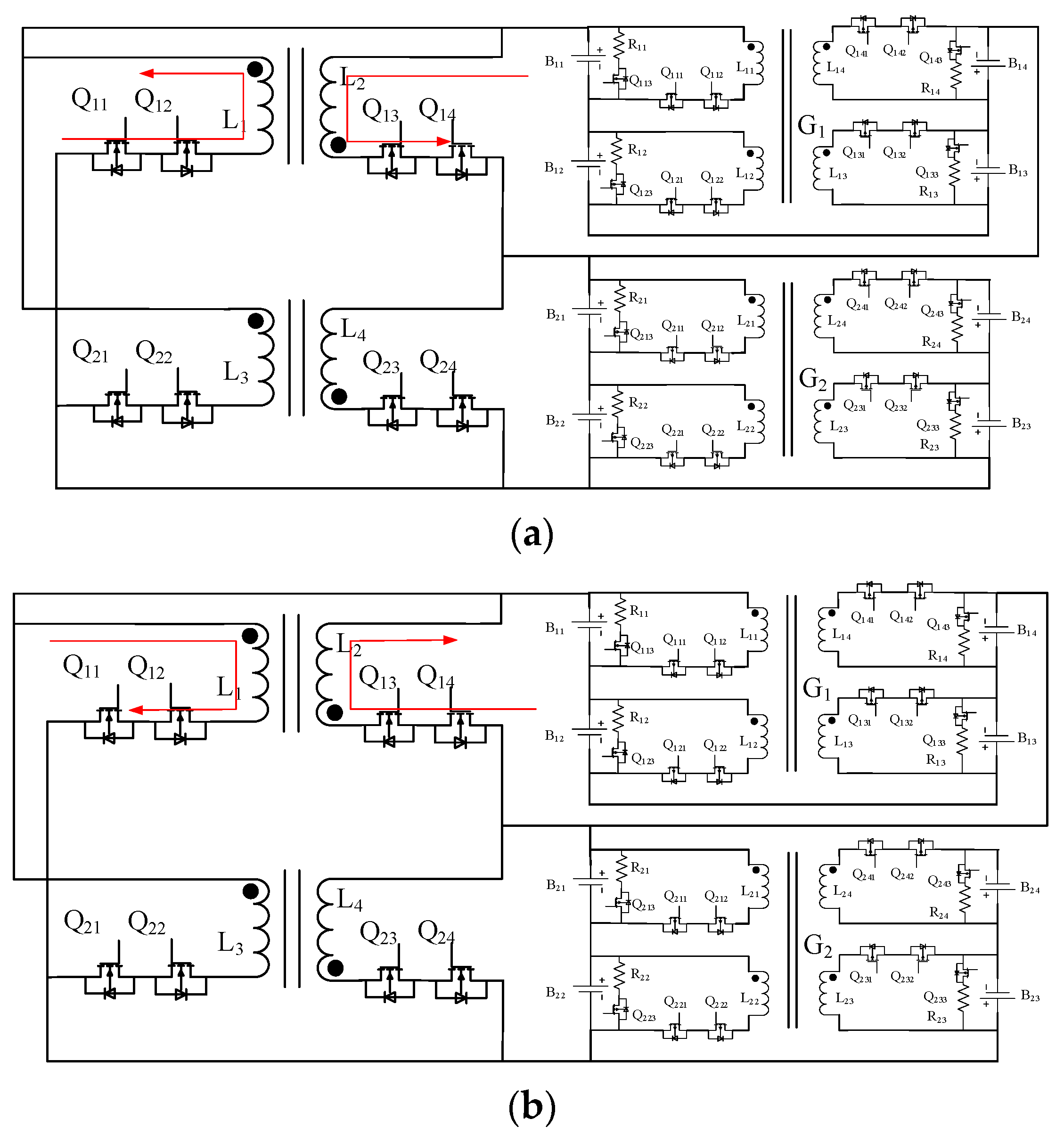
If the target battery and the source battery are on different sides of the battery group, the energy is transferred between the batteries by the Flyback operation. Assuming that
B11 is the source battery and
B13 is the target battery, at time
t1,
Q111 and
Q112 are turned on,
Q113 and all other MOSFETs are turned off. The energy is transferred from battery
B11 to transformer
L11 for storage. In [
t1,
t2], the discharge current is calculated as Equation (1), and the current flow direction is shown in
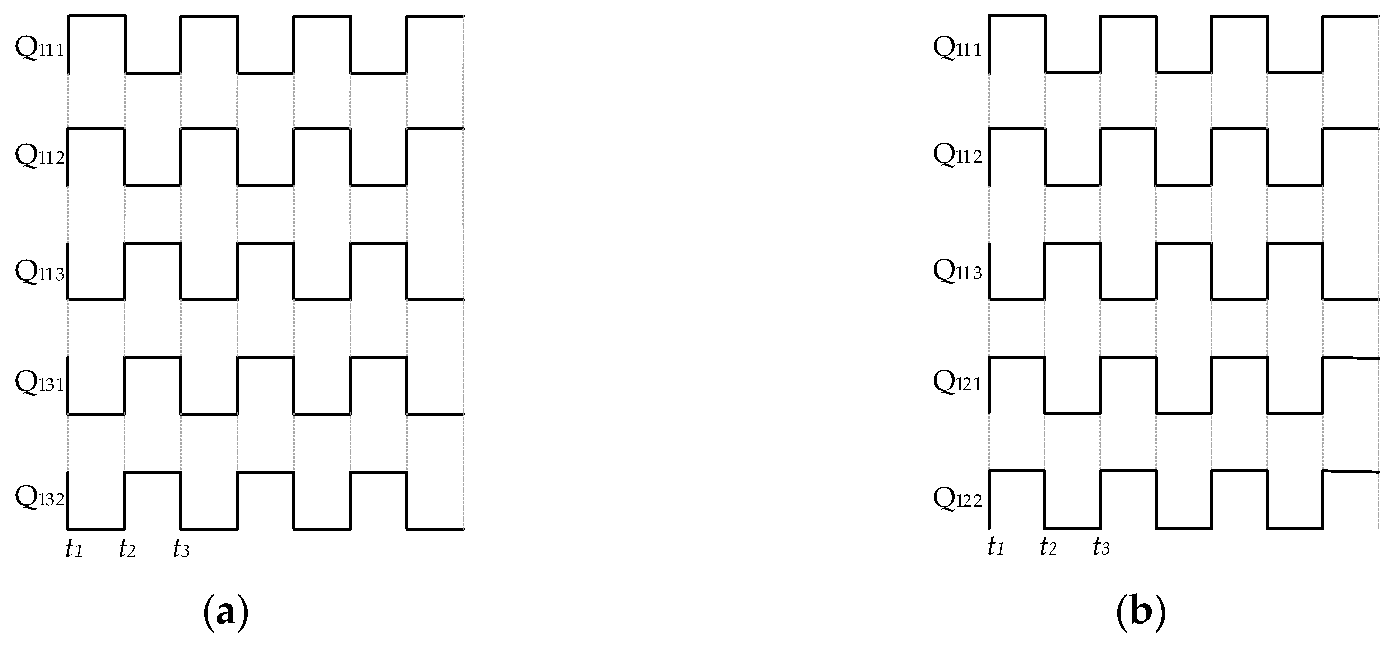
Figure 3a. At time
t2,
Q111,
Q112 and
Q113 are turned off;
Q131 and
Q132 are turned on. Most of the energy in
L11 is released to the Battery
B13. At this time, the current flowing through the inductor
L13 is located and can be calculated according to the superposition theorem, in Equation (3),
represents the initial value of the current at time
, the relationship between
and the current value
of the primary winding at time
is shown in Equation (2). The voltage across the winding
is clamped to voltage
by the battery cell, so
gradually decreases with time, Equation (3) expresses this decay process. Due to the leakage inductance of
L11, the current cannot be entirely transferred to the other side when
Q111 and
Q112 are turned off. At the time of [
t2,
t3], the charge current of
B13 is calculated as Equation (3). Eventually, the energy is transferred from
B11 to
B12. The MOSFET switching state of the whole process is shown in
Figure 4a:
1.2. MODE 2: In-Group Forward Mode
If the target battery and the source battery are on the same side and the voltage difference is larger than 150 mV, the energy is transferred between batteries by the forward operation. We assumed that
B11 is the source cell and
B12 is the target cell. At time
t1,
Q111,
Q112,
Q121, and
Q122 are all turned on, and the energy of the cell
B11 is directly transmitted to
B12 through the transformer. At time [
t1,
t2], the current is calculated as Equation (4), and the current flow direction is shown in
Figure 3b. At the time
t2, the switches
Q111,
Q112,
Q121, and
Q122 are turned off, the energy transfer is finished. In the [
t1,
t2], the maximum current value can be calculated as Equation (4). The
R represents the equivalent impedance of the entire loop:
Finally, the energy transformation from the source battery to the target battery is realized, and the MOSFET control signal for the entire process is shown in
Figure 4b.
1.3. MODE 3: In-Group Passive Balancing Mode
If the target battery and the source battery are in the same group, and the batteries do not satisfy the condition that the voltage difference is large enough, active equalization is not suitable. In this case, the topology adopts the passive equalization, which is very suitable for the equalization with the batteries with small inconsistencies. Take
B11 as an example:
Q113 is turned on and other MOSFETs are turned off. As shown in
Figure 3c. At this time, the on-resistance of the MOSFET is ignored, and the current can be calculated according to (4). The passive equalization of other battery cells is the same as the above process. Eventually, the excess energy is dissipated in the form of heat:
1.4. MODE 4: Between-Group Bidirectional Flyback Mode
If there is a difference between the battery groups, the topology adopts a between-group mode. The triggering condition of the mode is the maximum voltage difference larger than 80 mV. The bidirectional flyback active balancing circuit transfers energy from the higher-power battery group to the entire power supply system by controlling the switch of the MOSFET, or vice versa. This paper uses the balancing between two battery groups as an example to explain the working principle of the between-group balancing. As shown in
Figure 5a, assuming that the battery group where
B11 is in higher energy state, the battery group where
B11 is located serves as the primary side of the Flyback transformer, and the power supply system serves as the secondary side of the Flyback converter.
Q13,
Q14, and
Q11,
Q12 are turned on or off by complementary pulse-width modulation (PWM) driving signals, respectively. At this time, the battery group charges the whole power supply system through the flyback converter. The current flow is shown in
Figure 5a: the converter works in DCM mode, the duty cycle is set to 45%, and according to the transformer transformation ratio it is 1:m, with m being number of bottom groups, where m = 2 when
Q13 and
Q14 are turned on, battery pack
G1 charges winding
L2,
is the voltage value of
G1. The peak value of the primary charging current
is calculated according to Equation (6). Then, the average current value
is obtained by Equation (7). After that,
Q13 and
Q14 are turned off, and
Q11 and
Q12 are turned on. At this time, the secondary winding discharges to the entire top layer group, and the initial value of the secondary current is its peak value. Its value is represented by Equation (8), and the average value of the secondary winding current is represented by Equation (9):
In another case, when the energy of the battery group in the entire power supply system is lower than the average level, by controlling the corresponding MOSFET to be turned on and off, the energy of the entire power supply system can be transferred to the lower power battery group. Assuming that the power level of
B11 at this time is lower than the average level, the bidirectional flyback converter is configured as a buck converter to charge it. At this time,
L1 in
Figure 5a is the primary-side transformer winding, and (
Q13,
Q14), (
Q11,
Q12) are turned on or off by the complementary PWM drive, respectively. The whole power supply sysem is charged to the battery group with a lower energy level, and the current flow is shown in
Figure 5b, that when
Q11 and
Q12 are turned on,
is charged,
is the voltage of the top battery group, and its expression is Equation (11). At this time, the top group side is the primary side of the transformer, the peak charging current of the primary side is calculated according to Equation (12). Then, the average current value is obtained by Equation (13). After
Q11,
Q12 are turned off,
Q13,
Q14 are turned on, the secondary winding discharges to the battery group
G1. The initial value of the secondary current at this time is the peak value, which is expressed by Equation (14), and the average current value is expressed by Equation (15).
3. Simulation
MATLAB 2018b/Simulink was used to validate the topology proposed in this paper. This paper will verify the in-group and between-group balancing separately.
The intra-in-group balancing circuit was built by the components in the Simscape library in Simulink. The battery model parameters used in the simulation are used the parameters of ternary lithium battery, they are set as shown in
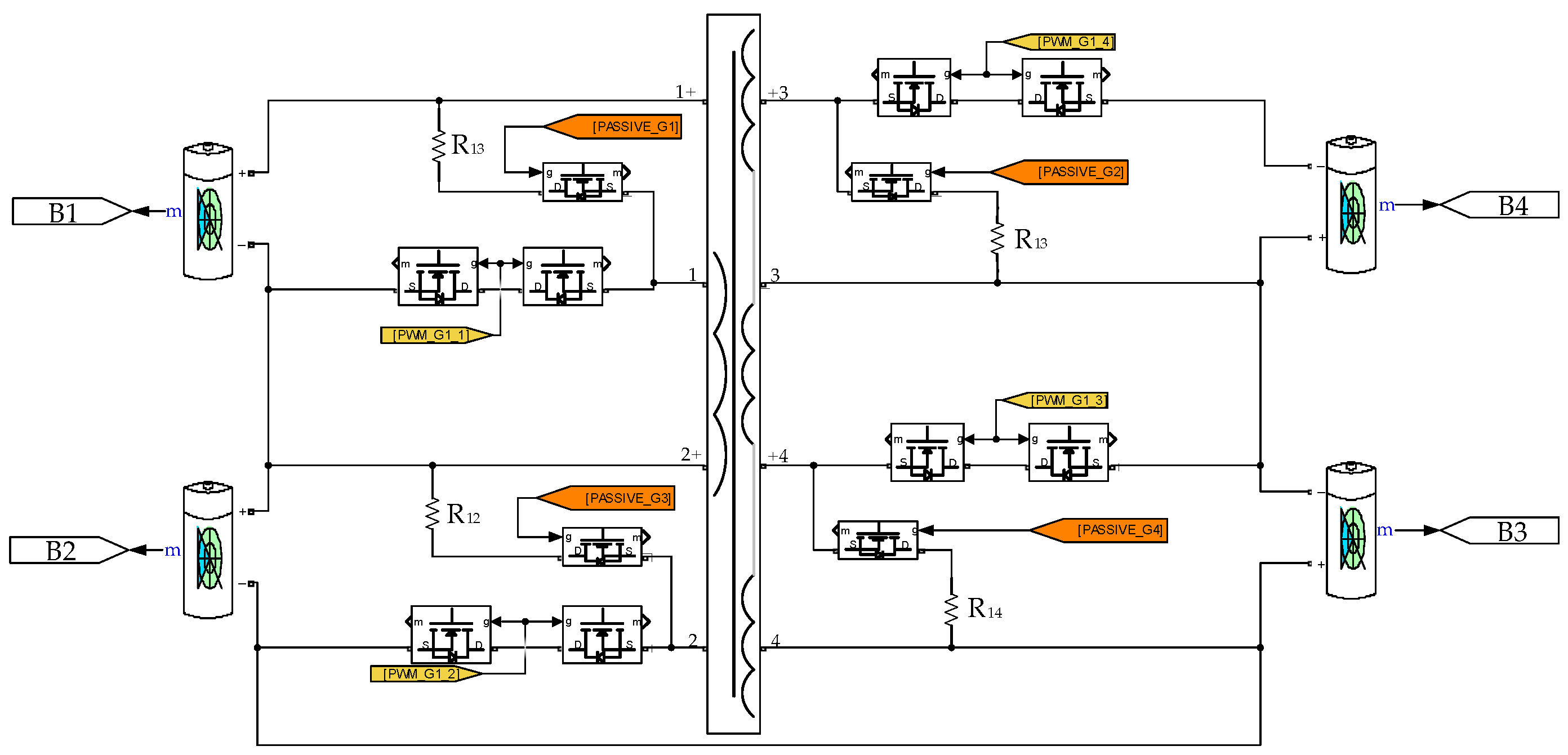
Table 3. The circuit is shown in
Figure 8, PWM_G1_1, PWM_G1_2, PWM_G1_3, and PWM_G1_4 are the driving signals of the bidirectional switch respectively, and each signal is a 100 kHz PWM waveform, Each bidirectional switch applies different drive waveforms according to different working modes, When the circuit works in the flyback equilibrium mode, the phase difference of the switching drive waveforms of the two cells for energy transfer is 180°, When in the forward equilibrium mode, the switching drive waveforms of the two cells for energy transfer are the same in phase. PASSIVE_G1, PASSIVE_G2, PASSIVE_G3, PASSIVE_G4 are control switches for passive equalization discharge resistance respectively, The switch is opened when operating the cell that needs to be discharged.
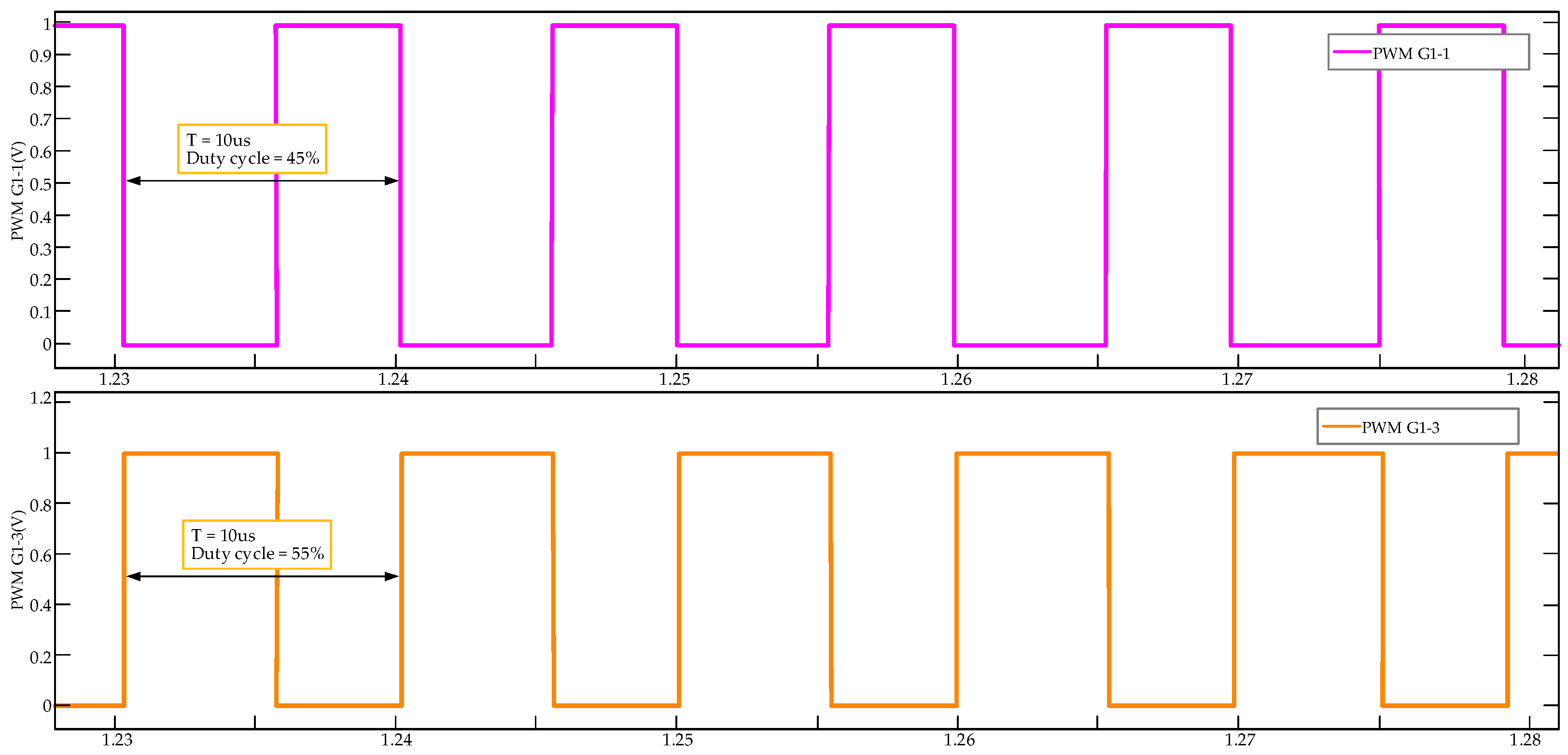
(1) In the simulation, MODE 1 is first verified. The condition that the balanced topology works in MODE 1 is that the highest and lowest battery cells are on different sides of the battery group.
B1 is the source battery in the balancing process, and
B3 is the target battery. The initial SOCs of
B1 and
B3 are set to 99% and 30%, respectively. At this time, the gate drive waveforms of the corresponding MOSFET in the balancing circuits of
B1 and
B3 were shown in
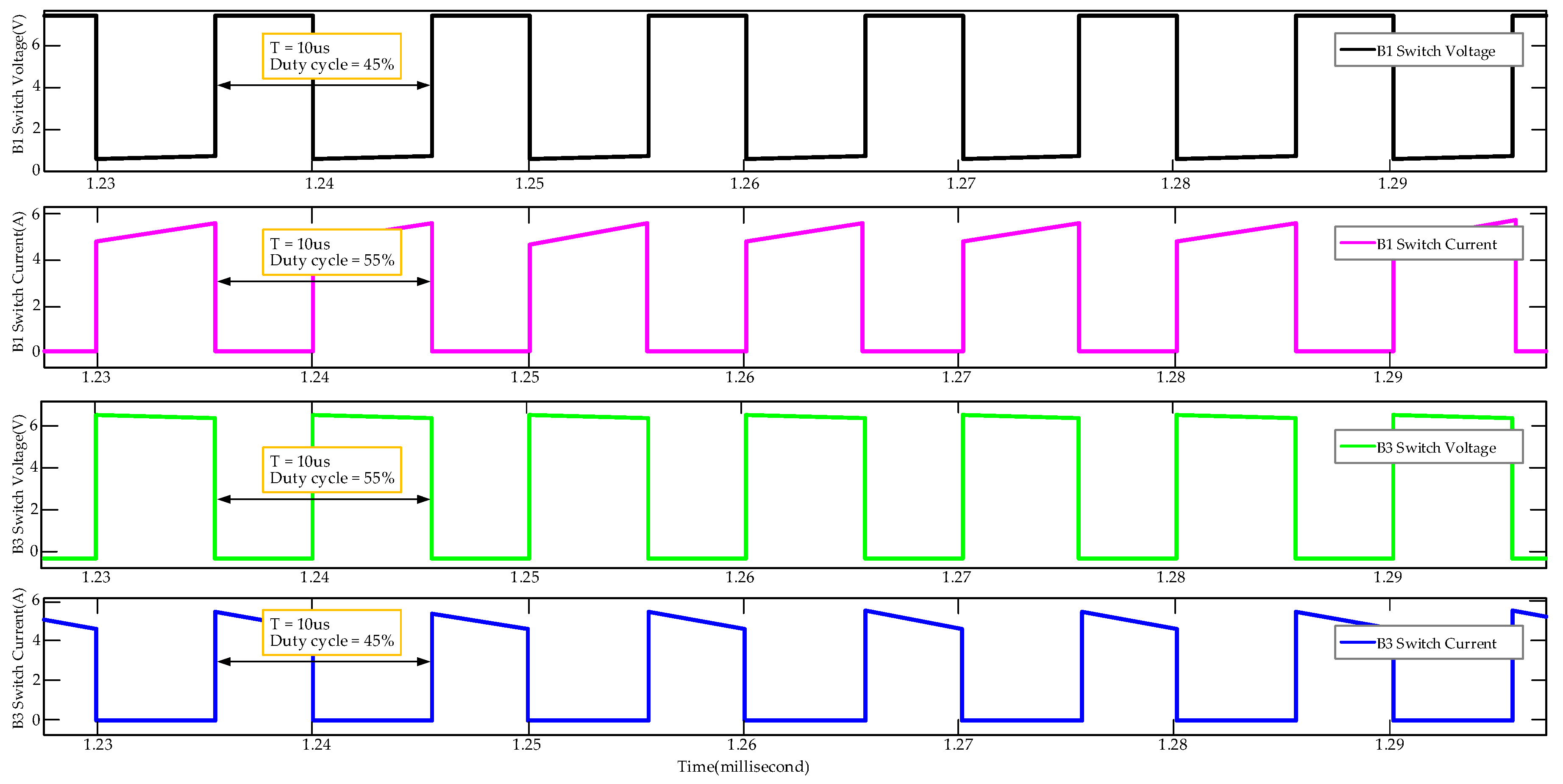
Figure 9. It can be seen that the phase difference between the two was 180°, so the PWM signals were complementary. The circuit worked in the in-group Flyback Mode. The current and voltage waveforms on the bidirectional switch are shown in
Figure 10: the working frequency was 100 kHz, the rated output power was set to 4.5 W, the efficiency was set to 85%, the duty cycle was set to 45%, the calculation process of the primary magnetizing inductance and leakage inductance were as processed in Equation (19), the transformer leakage inductance was estimated to be 5% of the magnetizing inductance, and the copper loss resistance of the primary winding was set to 25 m∙Ω.
According to the simulation results in
Figure 11, it is clear that the equilibrium time is 731.7 s. By Equation (20), the balancing efficiency of this equalization is about 82.1%. The simulation results show that the topology proposed in this paper can realize the balancing mode of MODE 1, and the balancing efficiency and equalization speed meet the expectation:
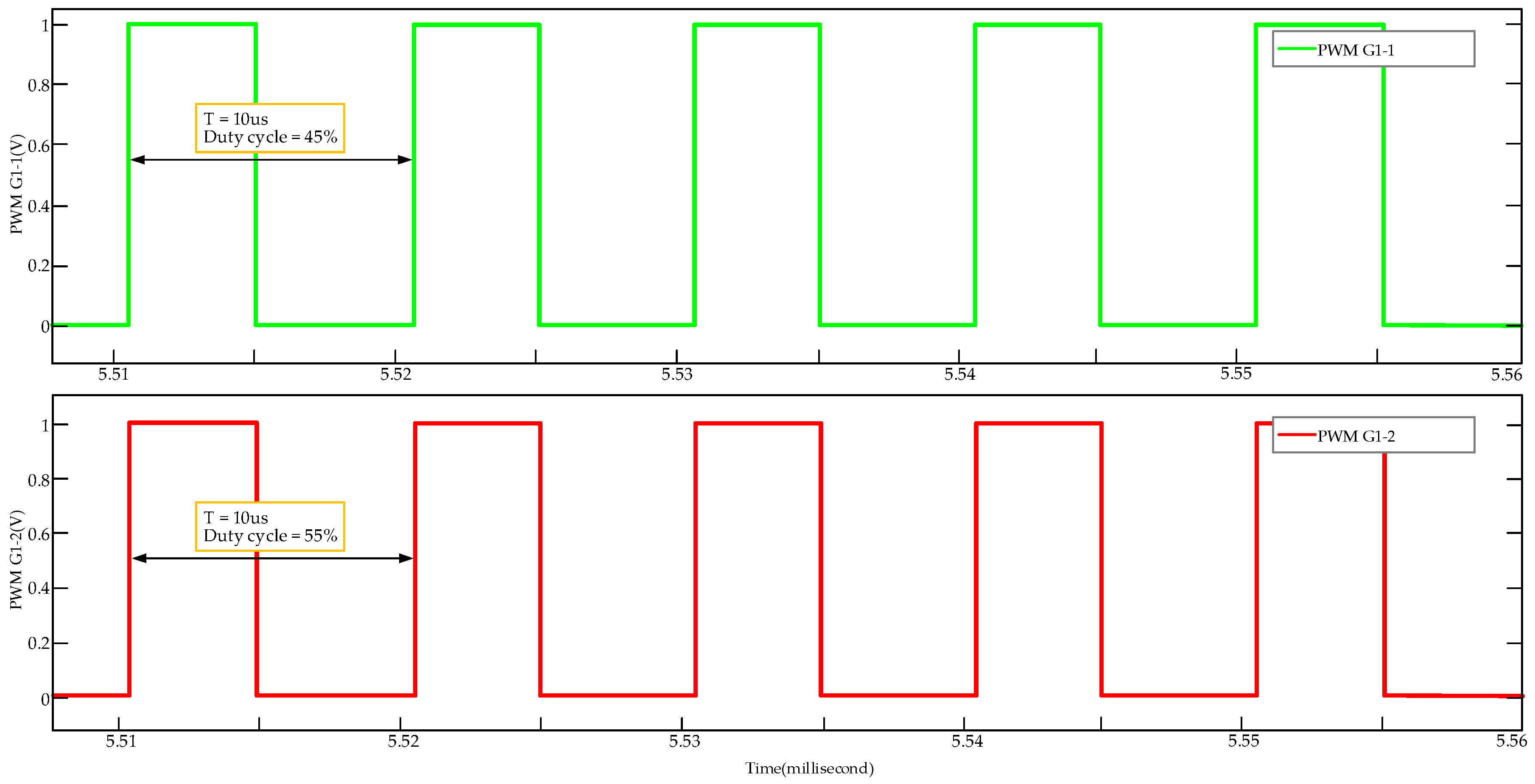
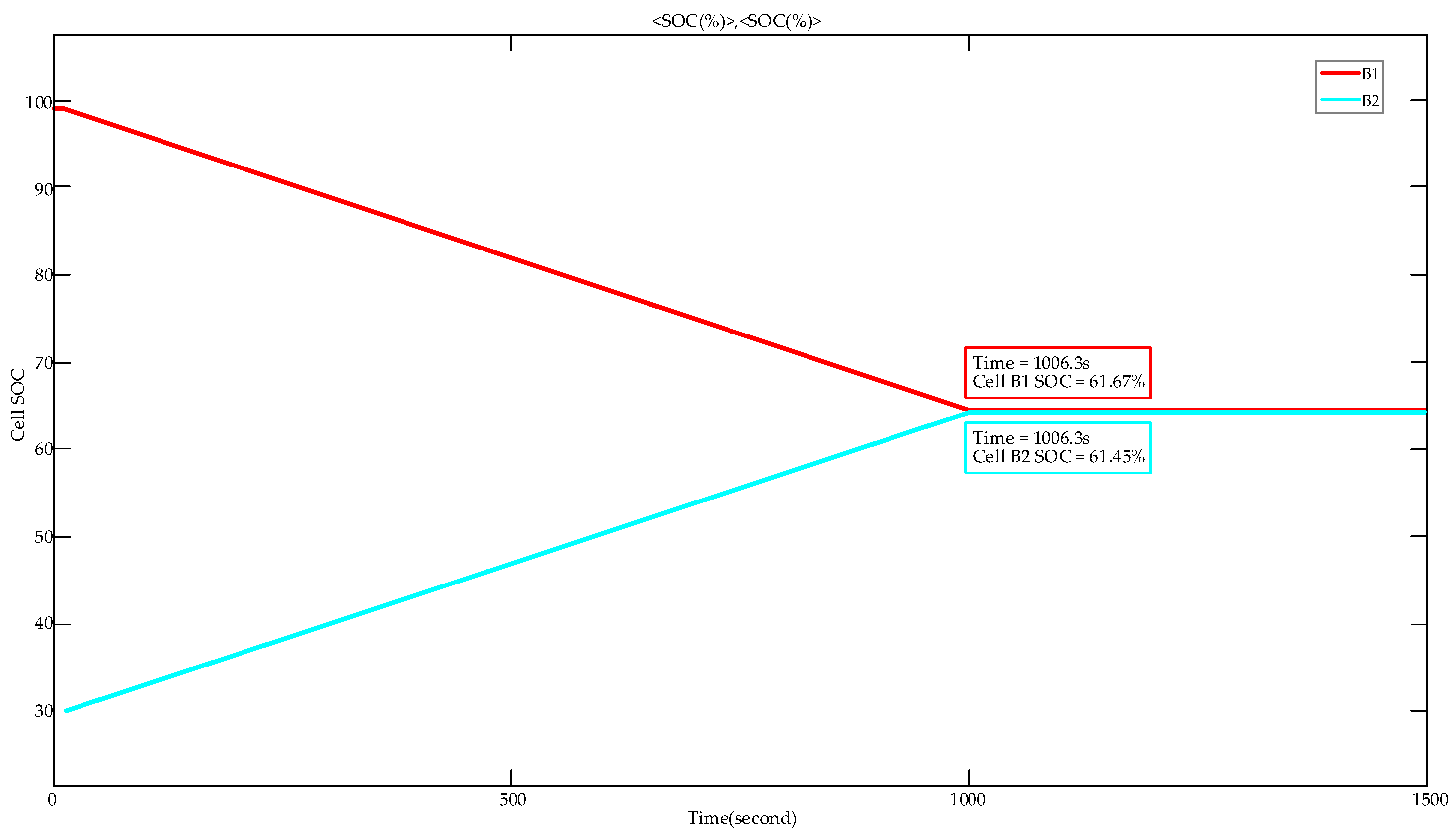
(2) In order to verify the MODE 2,
B1 was chosen as the source battery, and
B2 as the target battery.
B1 and
B2 are in the same side of the battery group. The initial SOC of
B1 was set to 99%, and the initial SOC of
B2 was set to 30%. At this time, the gate drive waveforms of the corresponding MOSFET in the balancing circuits of
B1 and
B2 are shown in
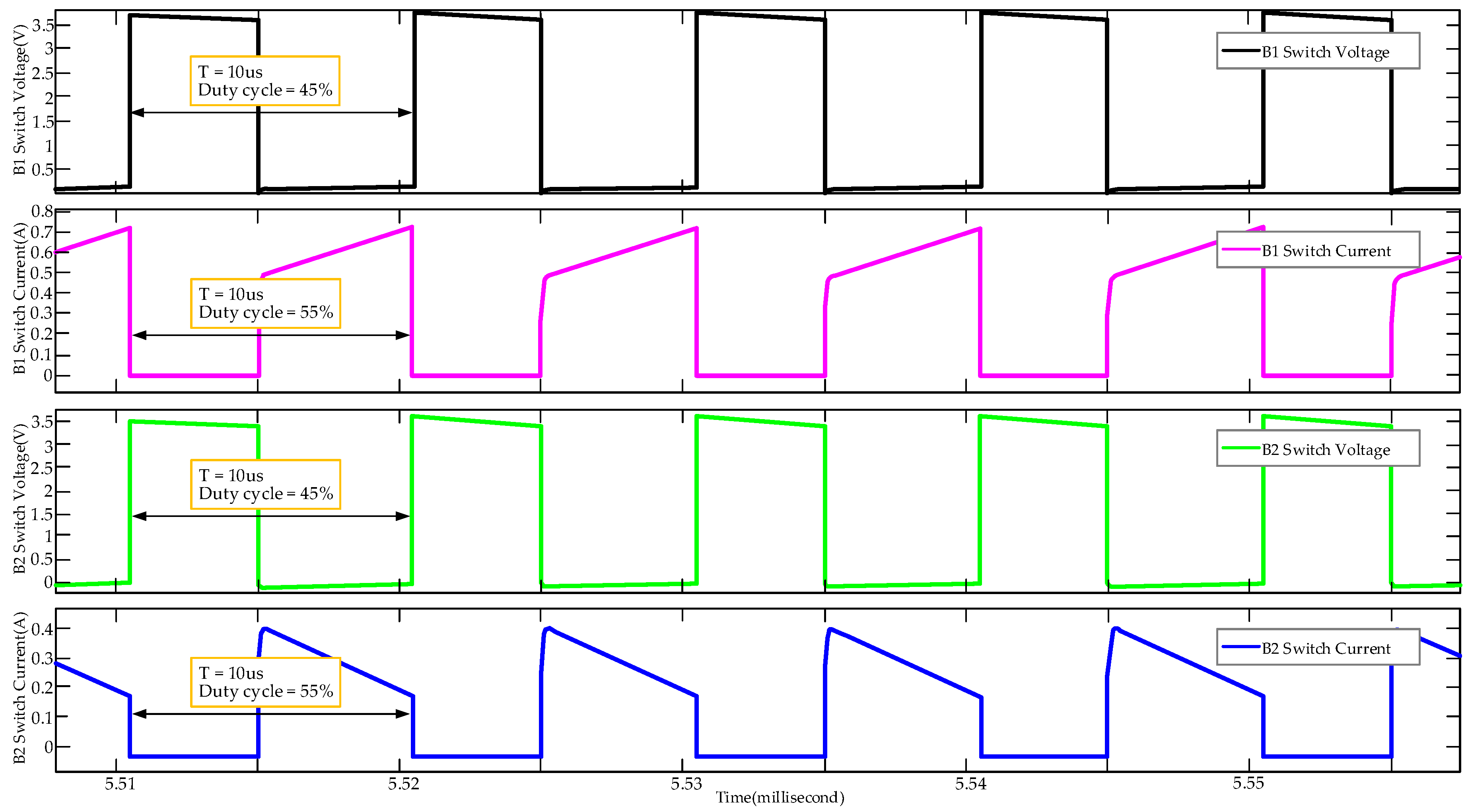
Figure 12. It can be seen that the phase difference between the two is 0°, so that they are in-phase PWMs. The circuit works in the In-groupForward Mode. The current and voltage waveforms on the bidirectional switch at this time are shown in
Figure 13. MODE 2 requires that the battery voltage difference exceeds the threshold, so at this time, the equalization time is completed at 1006.3 s by
Figure 14. After balancing, the SOCs of
B1 and
B2 are 61.45% and 61.67%, respectively. Compared with the in-group flyback mode, it takes a longer time. The balancing efficiency of this calculation is 95.4% according to Equation (21):
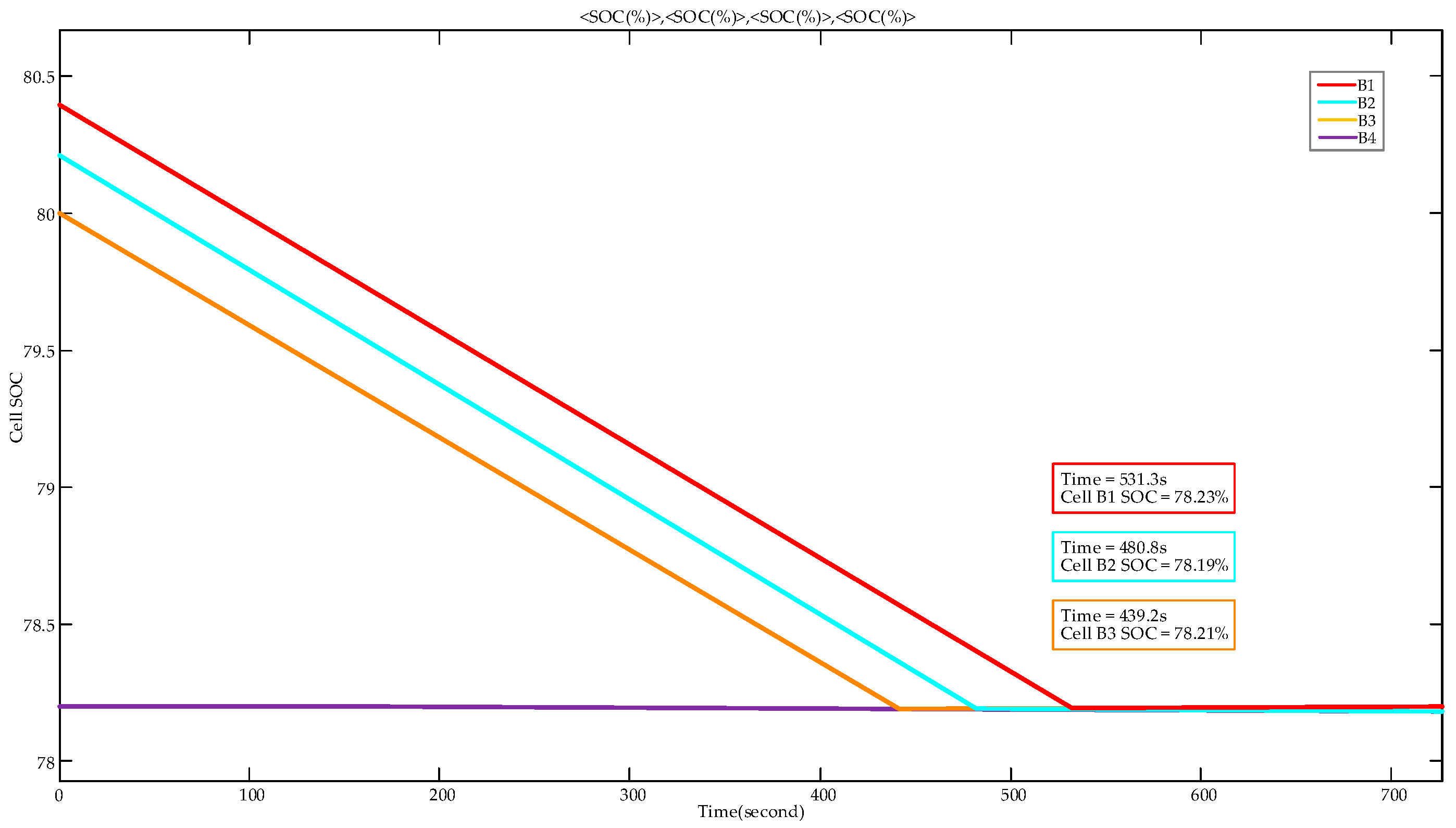
(3) This paper then verified MODE 3, in the in-group passive balancing mode. This mode requires that the SOC difference between the battery cells is less than 150 mV. The SOCs of four batteries are set to 80.4%, 80.2%, 80%, and 78.2%, respectively. At this time, the corresponding battery voltages are 3.465, 3.463, 3.459, and 3.443 V, and the maximum voltage difference is 22 mV, which exceeds the threshold of passive equalization. The SOCs at the final termination are 78.19%, 78.21%, 78.23%, and 78.18%, respectively. The entire balancing process takes 531.3 s. The SOC change curve in the process is shown in
Figure 15.
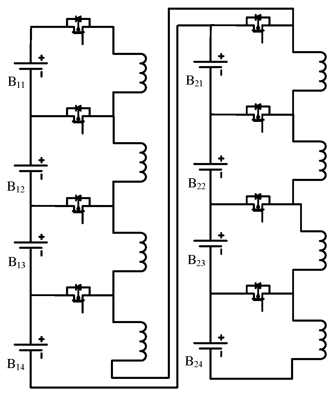
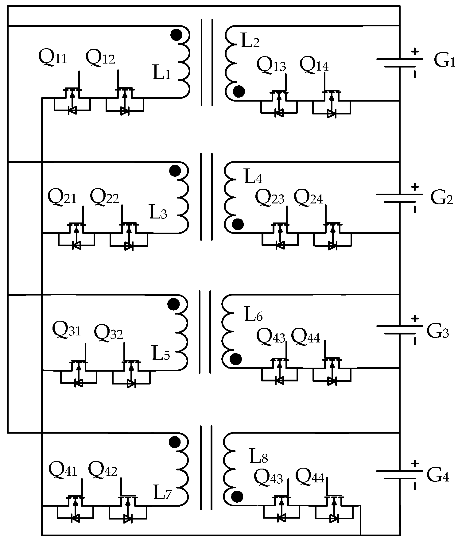
(4) MODE 4 is the between-group bidirectional flyback mode. In
Figure 16, taking the power supply system composed of four battery groups as an example, the energy exchange between the entire power supply system and one of the battery groups is used to achieve a balanced effect.
The between-group balancing should wait until the end of in-group balancing. Each battery group in the power supply system is equivalent to a large-capacity battery cell. Because the battery group is connected in series, the capacity of the equivalent battery group is equal to the sum of the capacities of all the batteries in it, and the voltage of an equivalent battery group is equal to the sum of the voltage of all the series batteries in it. G1, G2, G3, and G4 are used to represent four battery groups in the power supply system, each of which has a rated voltage of 13.2 V.
The between-group balancing proposed in this paper adopts different control strategies for two different situations. First, the average voltage value of the four battery groups is obtained, and the number of battery groups that are lower than the average value and higher than the average value are obtained through comparison. If the number of battery groups higher than the average value is greater, the entire power supply system is used to charge the battery groups that are lower than the average value. On the other hand, a higher-voltage battery group is used to charge the entire power supply system to achieve balance. The termination conditions of the two equalization methods are set such that the absolute value of the difference between the voltage values of all battery groups and the average voltage of the entire power supply system is less than 180 mV. The top-level active equalization simulation is carried out using the circuit diagram shown in
Figure 8, which only needs to reasonably set and modify the voltage of the battery, and one bottom-layer group is composed of four cells, its nominal voltage being
. The nominal voltage of the entire top layer group is
, the top group side is defined as the primary side, the turn ratio is set to 4:1, the output power of the flyback converter between groups is set to 40 W. The efficiency is calculated at 85%, the switching frequency is set to 100 kHz, the leakage inductance of the primary winding is estimated as 5% of the magnetizing inductance, the calculation process of the transformer parameters are expressed as Equation (22). The following will verify this mode:
- (a)
CASE 1: The entire power supply system charges a single battery group.
Considering the practical application, the experiment uses the voltage of the battery group as the variable of the between-group balancing. The initial voltages of G1, G2, G3 and G4 are set to 14.345 V, 14.320 V, 13.961 V and 14.292 V, respectively. At this time, the average voltage of the entire power supply system is 14.230 V, and an equalization strategy for charging the battery group G3 by the entire power supply system should be adopted.
At this time,
Q31,
Q32,
Q43, and
Q44, shown in
Figure 17, are controlled by two complementary PWMs, respectively, and the circuit with the same structure as
Q31 and
Q32 is hereinafter referred to as a bidirectional switch. The turns ratio of the transformer is selected as 4:1. Since the secondary group is charged for the primary group at this time, the side where
Q31 and
Q32 are located can be defined as the primary side. Correspondingly, the side where
Q43 and
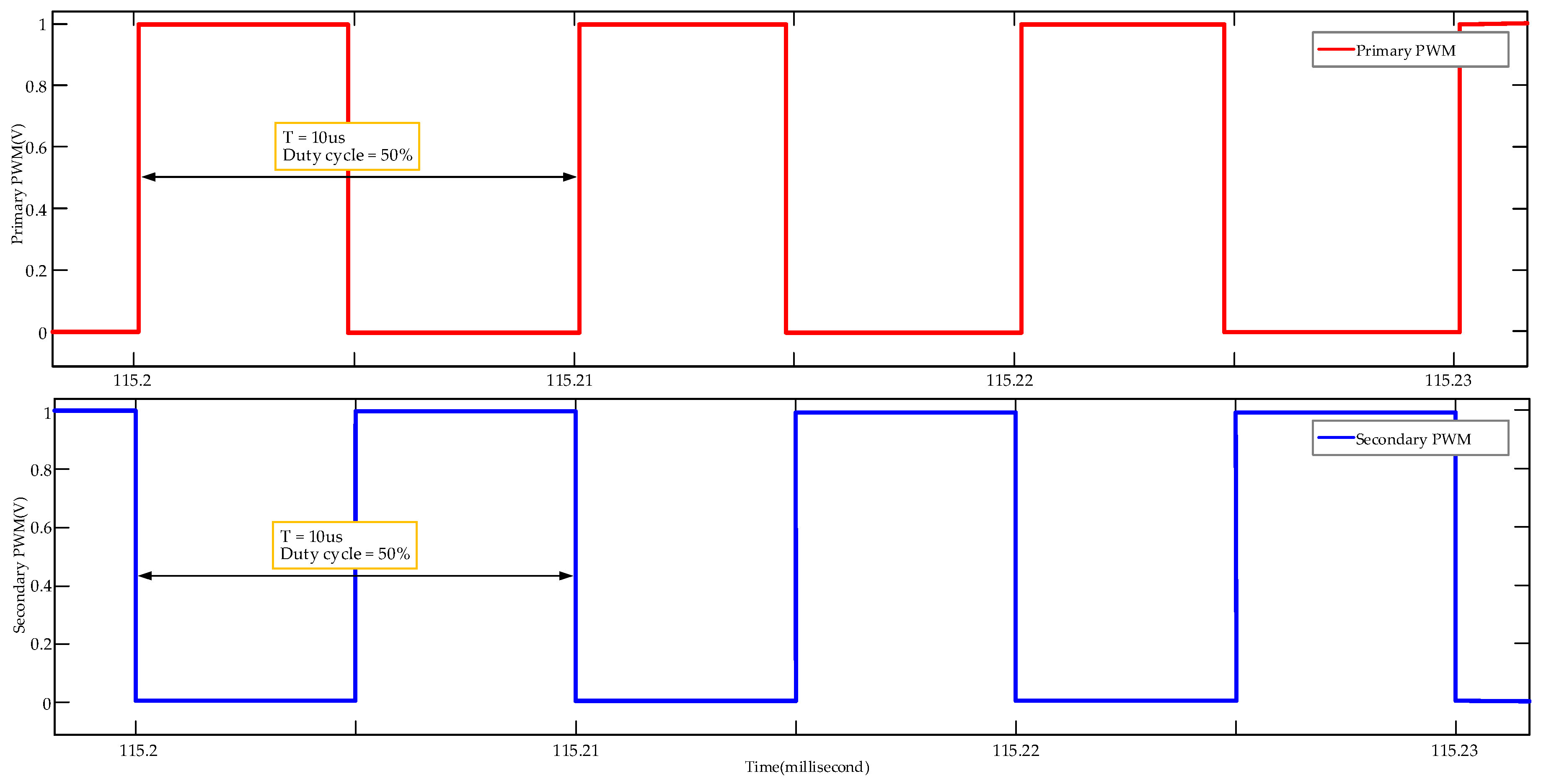
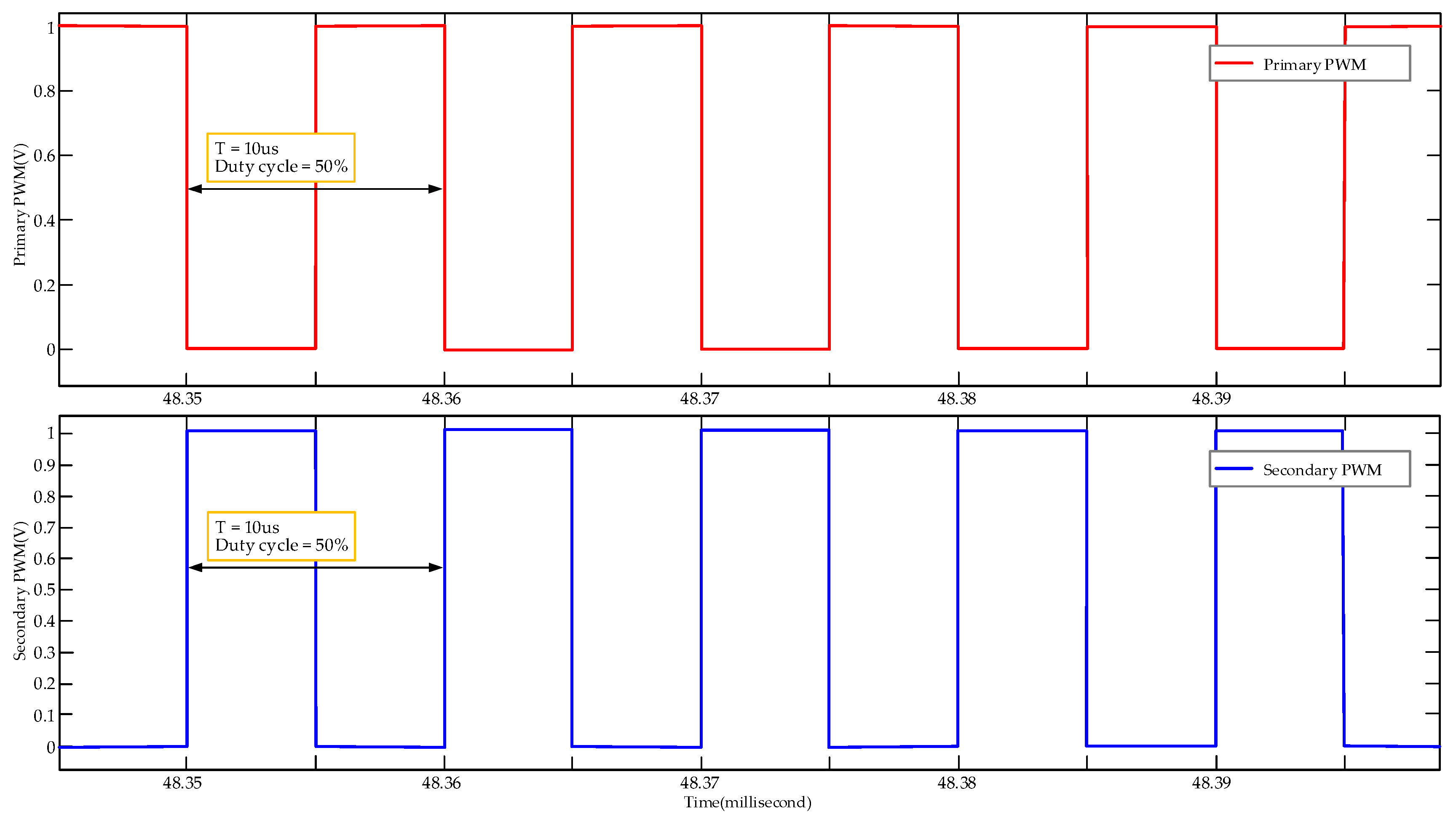
Q44 are located is the secondary side. At this time, the driving waveform of the bidirectional switch corresponding to the primary side and the secondary side is shown in
Figure 17, The primary side bidirectional switch is composed of
Q31 and
Q32 in
Figure 16, and the secondary side switch is composed of
Q43 and
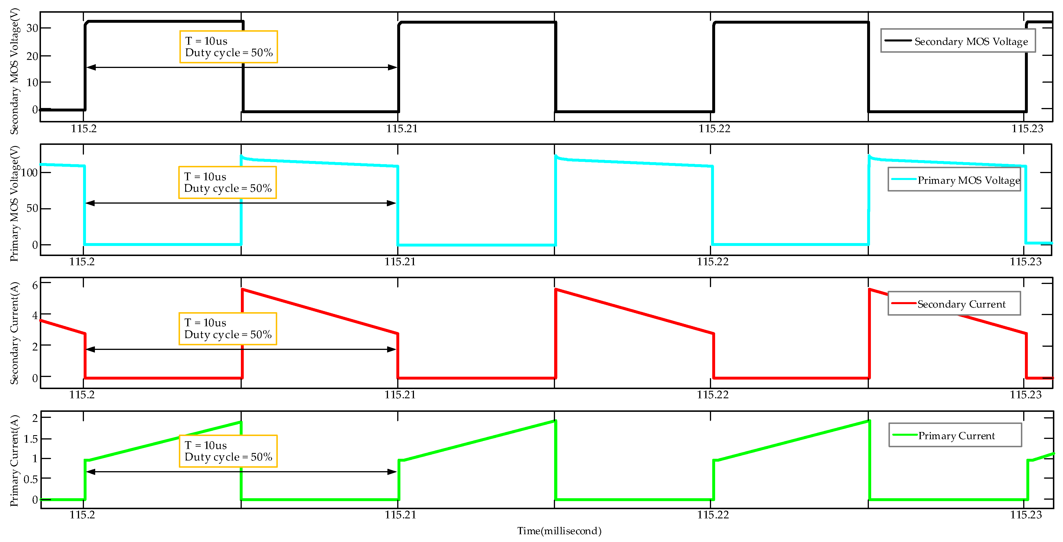
Q44, and the corresponding voltage and current waveforms of bidirectional switch are shown in
Figure 18. The battery group SOC change curve during the equalization process is shown in
Figure 19. After balancing, the voltages of
G1,
G2,
G3, and
G4 are set to 14.213 V, 14.243 V, 14.251 V and 14.260 V, respectively. The entire process takes 877.8 s. The equalization efficiency can be calculated according to Equation (23).
is the effective value of the voltage on the primary side, and
is the effective value of the current on the primary side.
is the effective value of the voltage on the secondary side, and
is the effective value of the current on the secondary side. The above four quantities are calculated as Equation (24).
After calculation, the equilibrium efficiency is .
- (b)
CASE 2: One battery group charges the entire power supply system.
In the power supply system, the initial voltages of
G1,
G2,
G3, and
G4 are set to 14.253 V, 14.275 V, 15.191 V, and 14.287 V, respectively. At this time, the battery group
G3 with the highest voltage should be used to charge the entire power supply system.
Q31,
Q32,
Q43, and
Q44 shown in
Figure 20 are controlled by two complementary PWMs, respectively. Since the entire power supply system is charged for the battery group at this time,
Q31 and
Q32 are located in the primary side, and
Q44 is on the secondary side. At this time, the driving voltage waveforms of the primary side and secondary side MOS driving voltages are shown in
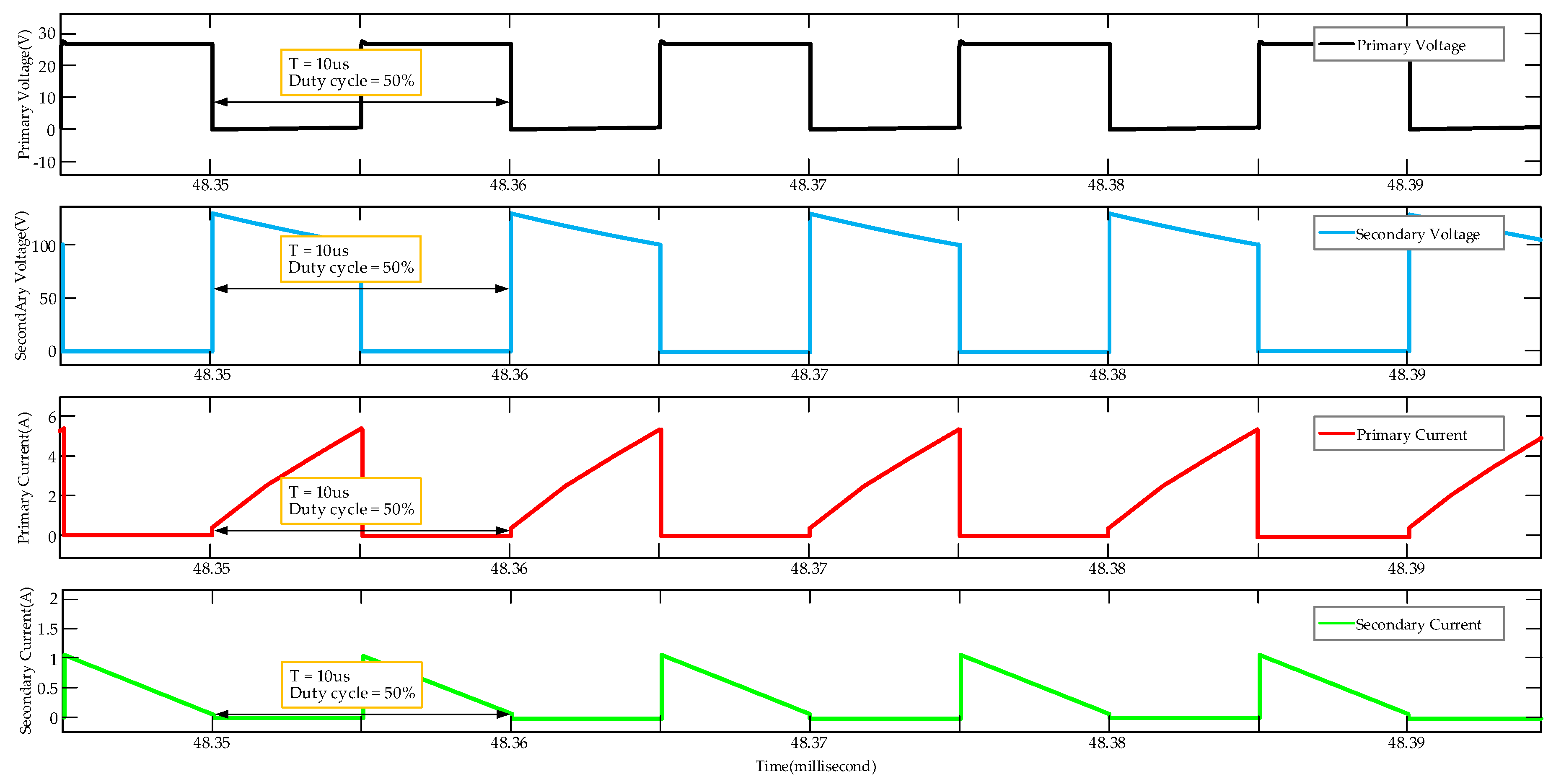
Figure 20, and the voltage and current waveforms are shown in
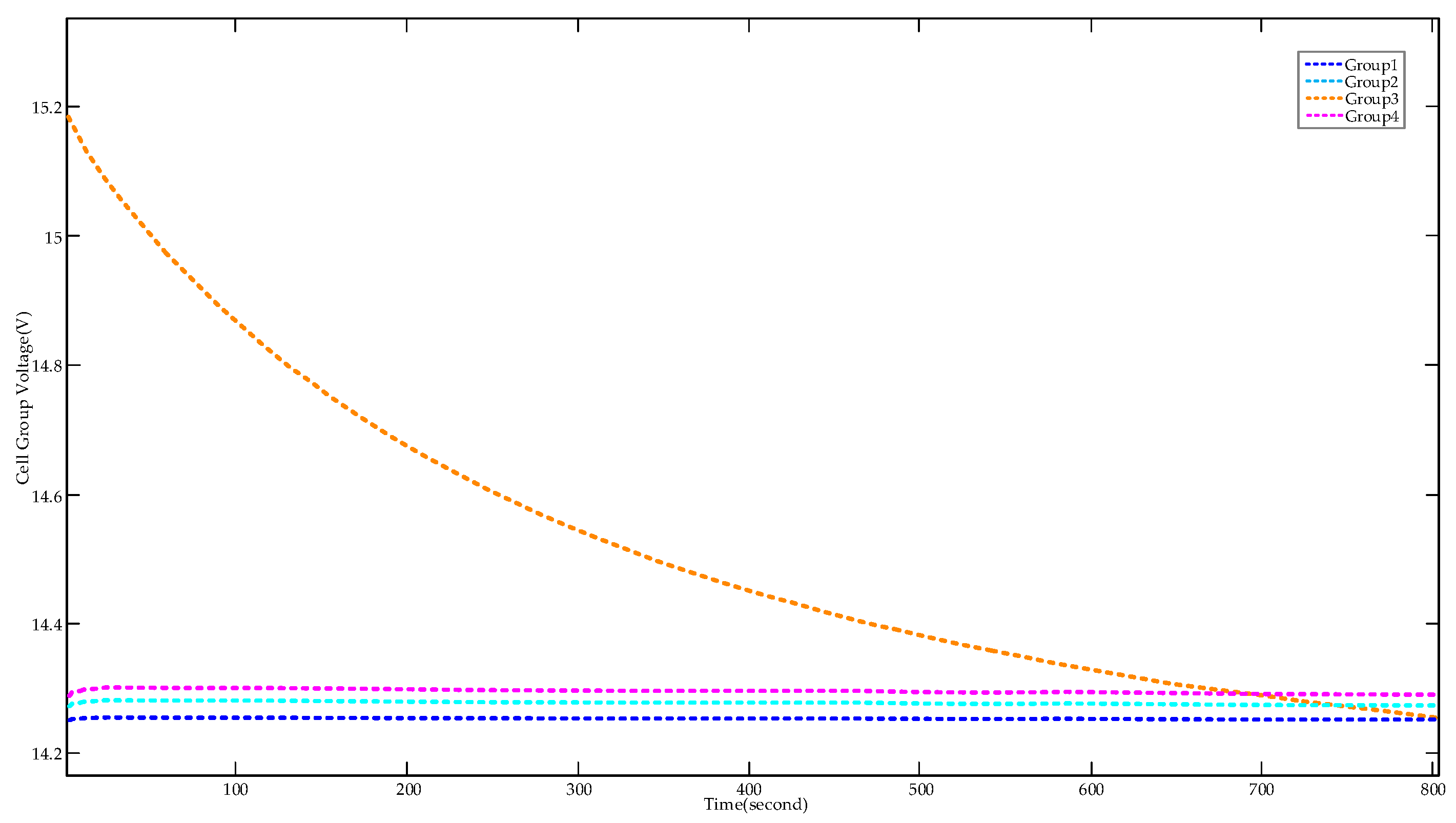
Figure 21. The battery group voltage change curve is shown in
Figure 22. After the balancing is completed, the voltages of
G1,
G2,
G3, and
G4 are 14.260 V, 14.284 V, 14.262 V, and 14.293 V, respectively. The entire process takes 803.8 s. According to Equations (20) and (21), the equilibrium efficiency is
.
4. Experimental Verification
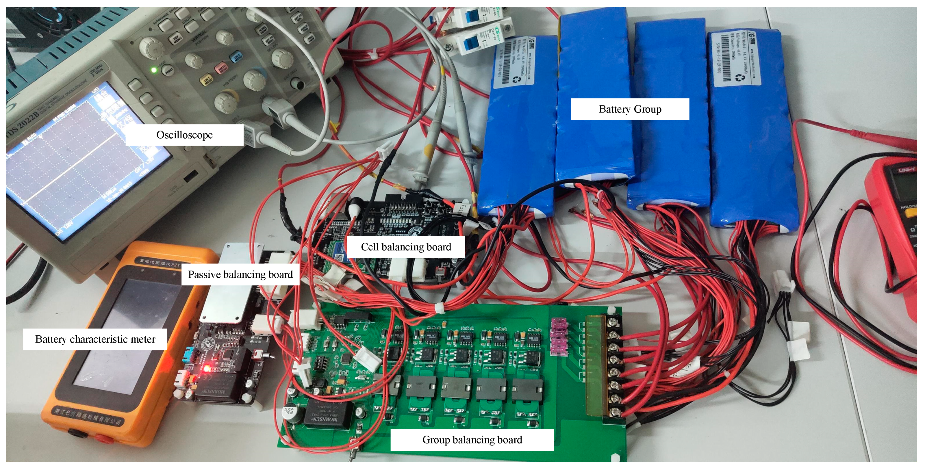
In this section, the simulation verification of the entire battery equalization system is completed, which proved the feasibility of the scheme. Based on the scheme, we produced a physical circuit system. The transformer used is a planar transformer with a small volume, and the coil is made of a multilayer printed circuit board (PCB). The multilayer PCB increases the apparent power of the transformer. The actual battery balance system consists of three STM32 series microcontrollers as the control core, the microcontroller models are STM32F103C8T6, STM32F030C8T6, STM32F407ZET6, respectively. The three balancing control boards communicate with each other through the CAN bus version 2.0B. The feasibility of the scheme is further verified by the physical circuit system, the battery parameters, key switching devices and transformer parameters, which are listed in
Table 4 and
Table 5, the calculation process of the theoretical value has been deduced in the previous chapter, so it is only listed here. The prototype is shown in
Figure 23.
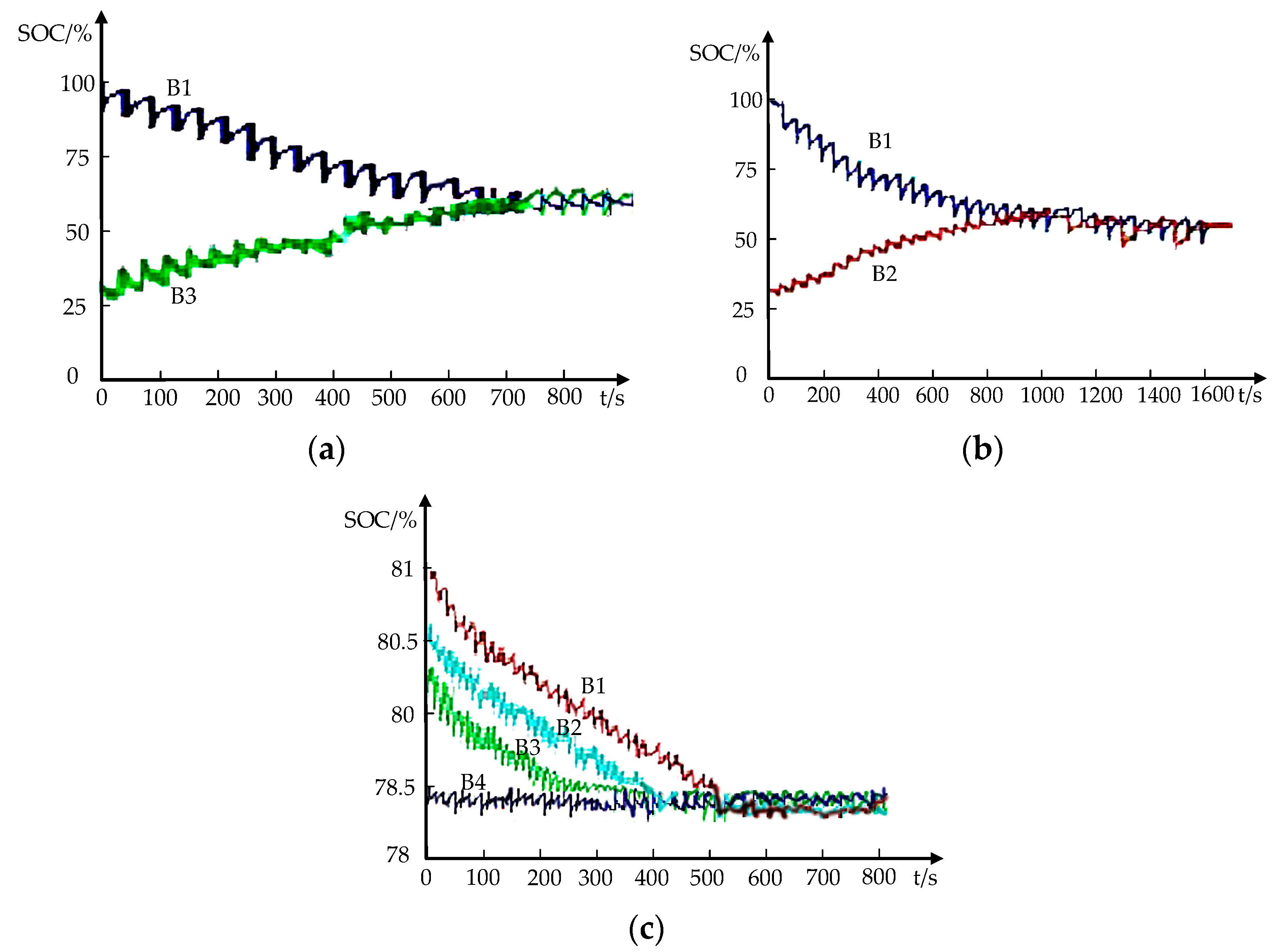
As shown in
Figure 24a–c, the experimental equilibrium data of MODE 1, MODE 2 and MODE 3 are obtained, which are basically consistent with the simulation results in
Figure 11,
Figure 14 and
Figure 15, respectively. Experimental results show that the proposed hybrid equalization strategy is effective.
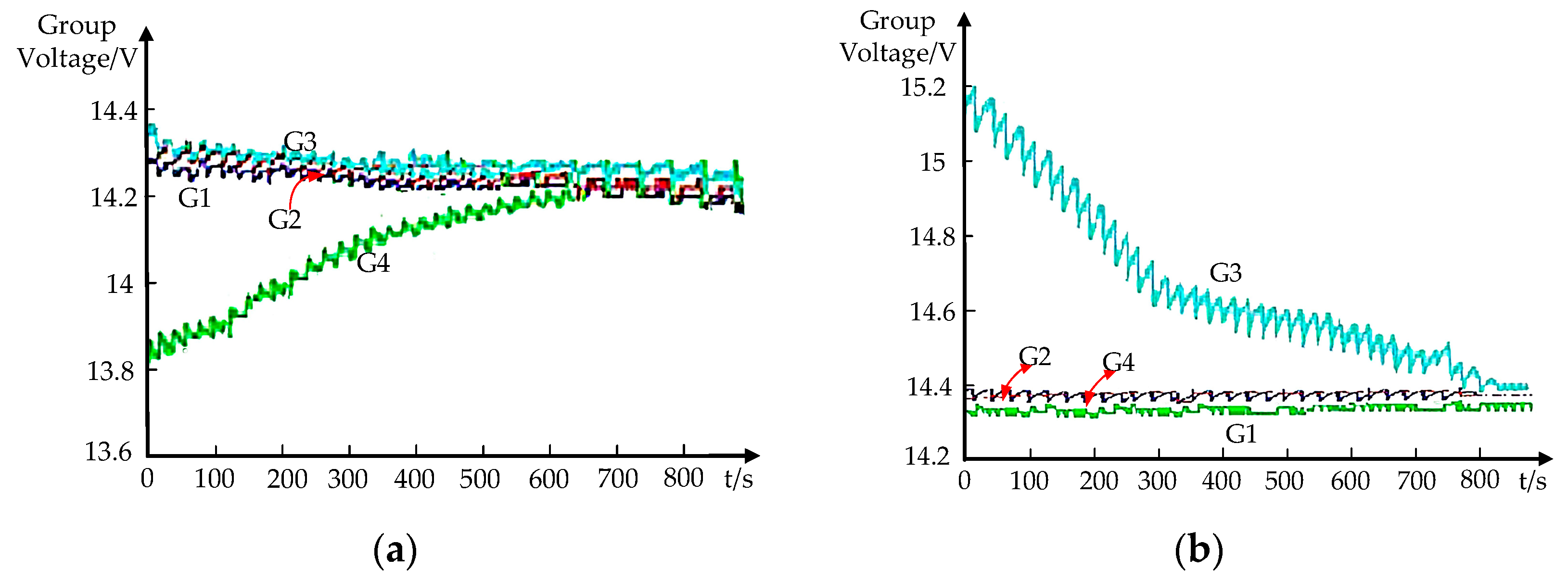
As shown in
Figure 25a,b, the experimental equilibrium data of CASE 1 and CASE 2 in MODE 4 are obtained, respectively, which are basically consistent with the simulation results in
Figure 19 and
Figure 22, respectively. Experiments further verify the effectiveness of the proposed hybrid equalization strategy.
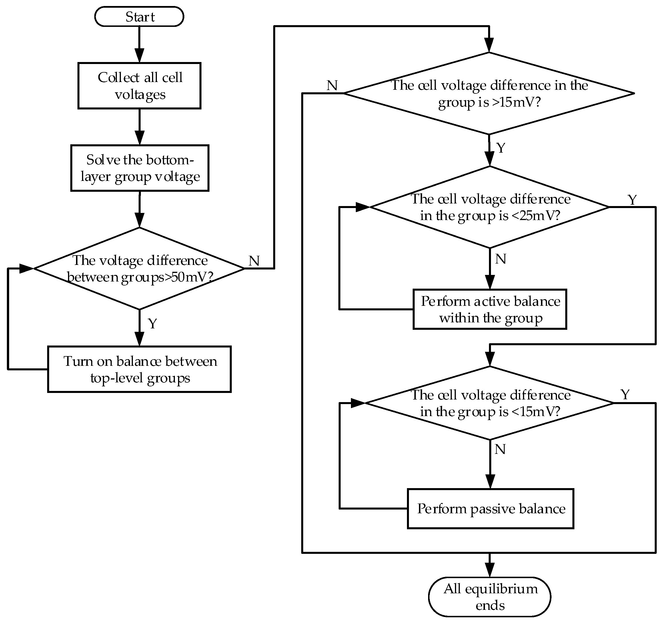
The following is an analysis of the balance process between the battery strings of other lengths. Taking a battery string composed of 20 cells as an example, the imbalance state is shown in
Table 6.
The unbalance conditions introduced above include unbalance within groups and unbalance between groups. The overall balance process is shown in
Figure 26.
According to the process shown in
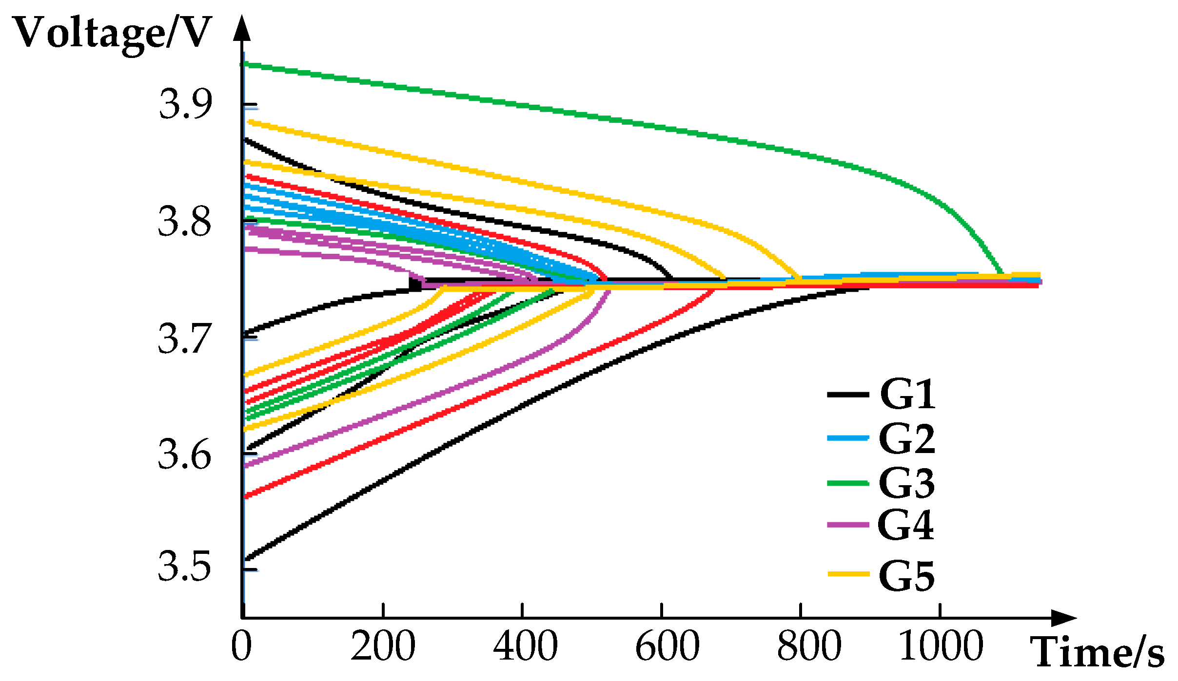
Figure 26 above, after the execution is completed, the gap between the batteries can be reduced to within the threshold range. This proves that the topology mentioned in the article has the ability to balance longer battery strings. As shown in
Figure 27, different colors represent different battery packs; the batteries imbalance condition is shown in
Table 6, according to the control strategy in this article, and this is the balancing process of five battery groups, a total of 20 battery cells.


