1. Introduction
Massive Multiple-Input Multiple-Output (MIMO) is a promising technology for the Fifth Generation (5G) of cellular networks [
1,
2,
3]. In Massive-MIMO, it is assumed that the number of transmit antennas is 10 times larger than the number of receive antennas [
1]. Such a massive number of antennas would provide significant multiplexing and diversity gains and serve a larger number of users in parallel [
2]. The theory has anticipated that in rich scattering environments, by increasing the number of transmit antennas, the greater data-rate can be achieved without increasing bandwidth [
3]. That is because, by adding multiple antennas, a greater degree of freedom, in addition to time and frequency dimensions, in wireless channels can be offered to provide more data-rate [
4]. Moreover, Massive-MIMO will minimize intra and inter-cell interferences, by narrowing and focusing the radiated energy toward the intended user’s direction [
3].
Although Massive-MIMO can provide numerous advantages over other prominent technologies, it is still involved with technical challenges and constraints that should be solved before its realization. Recent works [
5,
6] addressed the practical challenges of implementing Massive-MIMO in Time Division Duplex (TDD) and Frequency Division Duplex (FDD) modes. Among the addressed problems, the issue of interference cancellation is highlighted as one of the most challenging problems. It should be noted that in MIMO systems, the issue of interference cancellation is highly associated with the problem of accurate Channel State Information (CSI) acquisition at the Base Stations (BSs) [
7]. To tackle the problem, most studies consider Massive-MIMO in TDD mode, because of the channel reciprocity. In TDD mode, BS estimates the knowledge of the downlink channel through uplink training [
6]. However, in FDD mode, due to the lack of channel reciprocity, the downlink channel must be obtained from separate downlink training and User Equipment (UE) feedback scheme [
8]. Although both FDD and TDD modes are supported in current cellular networks, the FDD mode is the favorite industry mode, where the current cellular systems are mostly implemented in FDD, and the majority of the licensed frequency bands are explicitly assigned for FDD usage. Thus, this paper considers the MIMO system in FDD mode.
The Massive-MIMO system relies on spatial multiplexing, wherein FDD mode BS requires accurate Channel State Information (CSI) for interference cancellation. In the presence of perfect CSI at the transmitter, it is anticipated that Massive-MIMO can improve the system capacity by 10 times, versus Long Term Evolution Advanced (LTE-A) technology [
2]. However, in reality, the number of orthogonal pilot signals for channel estimation and uplink bandwidth for CSI feedback is limited [
9]. Therefore, to mitigate the interference between a large number of antennas, nearly all the resources of downlink and uplink channels will be occupied by the pilot signals and CSI feedback bits, respectively [
10].
The authors in [
11] and [
12] extensively investigated the performance of the Multi-User (MU) MIMO system under different phases of the conventional limited feedback technique and found out its challenges and limitations. Results revealed that the conventional limited feedback technique would not be able to perform effectively for complex MU-MIMO systems, such as Massive-MIMO. Therefore, to cancel the interference only based on the Physical Layer (PHY) procedures, more sophisticated methods are required for CSI quantization, receiving antenna combining, and precoding. Moreover, the authors in [
13] determined an optimal antenna deployment for the Distributed Antenna System (DAS) architecture that can enhance system performance in the MU-MIMO system. It was shown that by distributing all transmitter antennas throughout the cell, significant cell throughput could be achieved versus the conventional Centralized Antenna System (CAS). Results also revealed that DAS is more robust against imperfect CSI, where, with a limited number of feedback bits, the performance of DAS is significantly superior to CAS, especially in congested networks.
The work in [
14] proposed two algorithms to mitigate the problem of pilot contamination in a TDD Massive-MIMO system. The first algorithm dynamically groups UE into two groups, center and edge groups, based on the path loss. The second algorithm proposes a decontamination scheme by utilizing pseudo-random codes to assign orthogonal pilots to different cells. In [
15], the authors proposed a multi-stage recursive Grassmannian quantizer that enables a significant complexity reduction in CSI quantization. The authors extended their work in [
16] and applied the deep learning classification algorithms to further reduce the complexity.
Recently, a two-stage beamforming strategy, termed as Joint Spatial Division and Multiplexing (JSDM) was introduced. The authors in [
17] proposed a generalized JSDM approach for FDD Massive-MIMO systems. In this strategy, UE feeds back the inter-group CSI to the BS for joint group precoding and virtual user-based per-group precoding. In [
18], the authors proposed neighbor-based JSDM beamforming which, by adaptively classifying the UE as neighbors and non-neighbors, the scheme can fully utilize signal space and enhancing the system spectral efficiency.
The works in [
19,
20] proposed pregroup precoding methods based on the Zero Forcing (ZF) strategy for Massive-MIMO systems with imperfect CSI. The results show that in spatially correlated massive antenna environments, the proposed schemes can achieve higher gains over the conventional ZF techniques. In [
21], the authors proposed methods for statistical eigenmode-based UE grouping and outer beamforming for high altitude platform Massive-MIMO systems. The authors claimed that the proposed schemes could reduce the complexity associated with the computation of singular value decomposition in conventional methods.
In [
22], the authors proposed a compressive feedback beamforming scheme based on extracting the angular and spatial domain sparsity of Massive-MIMO channels. In this method, UE generates compressed feedback content using the angle-domain sparsity of channel and then conveys it back to the BS. Although the simulation results demonstrated the potential of the proposed method to achieve considerable performance gain over conventional feedback schemes, the scheme is still involved with technical limitations such as CSI feedback accuracy, CSI feedback overhead, and a limited number of transmit antennas.
The work in [
23] proposed a protocol for fast fading FDD Massive-MIMO systems. The approach relies on Device-to-Device (D2D) cooperation to avoid instantaneous CSI feedback. In this protocol, UE cooperates to generate a virtual MIMO, while it is assumed that the BS is aware of downlink CSI as well as UE cooperation. Nevertheless, the assumption that the transmitter is aware of CSI in advance is unrealistic. The authors in [
24] proposed a projection-based differential feedback protocol to reduce the number of feedback bits for Massive-MIMO. In this protocol, a difference between original and predicted vectors is projected, and quantization is performed in a smaller dimensional subspace. The strategy exploits both temporal and spatial correlation of the Massive-MIMO channel. However, the employed prediction method enhances the system complexity, especially in the presence of a large number of antennas.
The authors in [
25] proposed a new metric for the UE scheduling to increase the multi-user diversity gain in the FDD Massive-MIMO system. The metric was derived based on an approximate lower bound of expected Signal to Interference plus Noise Ratio (SINR) value. Additionally, the authors proposed a new user grouping algorithm to reduce inter-group interference. This work assumed that the BS has perfect knowledge of the channel covariance matrix, while in reality, acquiring even a rough estimation of CSI in an FDD Massive-MIMO system is highly challenging.
Chen et al. in [
26] proposed a precoding scheme for the Massive-MIMO system. The scheme is based on spatial coordination and exploiting the null-space of user signals, where to avoid interference, the BS precodes the signal within the null-space of the victim UE’s channel. This scheme suffers from a prohibitive amount of feedback requirement and encoding complexity, especially for the case of Massive-MIMO, when the number of transmit antennas is massive. The authors in [
27] proposed a CSI feedback strategy for the FDD Massive-MIMO system. In this strategy, UE is grouped into two classes according to their channel covariance. To do so, a Signal to Interference-plus-Noise Ratio (SLNR)-based precoder was developed for handling the instantaneous and statistical CSI. The authors claimed that the proposed strategy could outperform the conventional limited feedback strategy under a limited number of feedback bits.
As addressed, the aforementioned interference cancellation strategies mainly suffer from high computational complexity and CSI feedback overhead, which is due to the utilization of a conventional cell-centric interference cancellation strategy. To effectively cancel interference by conventional limited feedback techniques, precise cooperation between transmitter and receiver is required, which results in some technical challenges. One of the main challenges is utilizing complex optimization techniques at the receiver to jointly maximize the channel gain and minimize interference leakage. This is because UE should estimate the weight vector due to the non-cooperative nature of the channel. Another technical challenge is the computation of effective channel direction at the receiver side, in which the accuracy of channel direction directly affects the performance of the precoder at the transmitter side. The design of the codebook for quantizing CSI and exploiting the spatial dimensions of the channel matrix is highly challenging, especially when the scale of the system increases, which directly impacts the CSI feedback load and CSI accuracy. The last but not least technical challenge is the computational complexity of the precoder at the transmitter, while the complexity enhances by the channel dimension and the performance is limited by the accuracy of the quantized version of the estimated value of the effective channel.
This paper aims to propose a novel interference cancellation strategy for the FDD large-scale MU-MIMO system. To do so, instead of assigning the task of interference cancellation to the BS, like conventional limited feedback strategies, the main task is assigned to the UE. In this strategy, adjacent active UE shares knowledge of its estimated downlink channel to jointly adjust the receive antenna combiner weight vector, which reduces the complexity of receiver combiner computation, as well as channel direction computation. To reduce the dependency of downlink transmission performance on CSI’s accuracy, the computation method of the receive antenna combiner weight vector is developed in such a way that maximizes the effective channel gain, which consequently reduces the precoder computational complexity, as well as CSI feedback overhead.
We would like to emphasize that the proposed strategy should not be viewed as a complete scheme to cancel interference in a Massive-MIMO system. Instead, it is a general concept for changing the limited feedback interference cancellation strategy from the conventional cell-centric to a user-centric. Therefore, the downlink channel estimation, quantization, and precoding methods are not restricted to the utilized schemes, and any of the existing methods can be employed.
The key contributions of this paper are summarized as follows:
A new algorithm is developed for correlated UE clustering. The K-means algorithm is utilized to determine the correlation between the estimated downlink channel matrixes of adjacent UE. Proximate UE that experiences correlated large scale fading are clustered into a group for CSI sharing.
A new scheme is proposed for jointly setting the receive antenna weight vector. To reduce the dependency of the downlink transmission performance on CSI feedback accuracy, the main task of interference cancellation is assigned to the UE. Hence, UE, based on the Multi-user Eigenmode Transmission (MET) technique and by knowing its classmates’ CSI, starts to jointly set its receive antenna combiner weight vector to maximize its effective channel gains.
A new scheme is proposed to reduce the CSI feedback overhead. In this scheme, instead of UE feeding back its CSI individually to the BS, each cluster’s head feeds back only the common CSI to the BS.
The performance of the developed interference cancellation strategy is validated by link-level simulation, and the system throughput performance is evaluated under CAS and DAS configurations. The simulation results show that the proposed strategy can be effectively applied to the MU-MIMO systems, especially when the network is congested, and a large number of transmit antennas is utilized.
The rest of this paper is organized as follows.
Section 2 presents the system model and the limited feedback technique for the MU-MIMO system.
Section 3 proposes different phases of the proposed User Cooperative Interference Cancellation (UCIC) strategy.
Section 4 validates the performance of the developed interference cancellation strategy in different scenarios, and
Section 5 concludes the paper.
Notation: we use uppercase for matrices, lowercase for vectors, and calligraphic for sets. The norm of a vector is denoted as , and denotes the Frobenius norm of a matrix. The size of a set is given by . is the inverse of a matrix. The Moore–Penrose pseudo inverse is . means is a matrix with size . denotes a complex-valued circularly symmetric Gaussian random vector , with means and variance . denotes the transpose of a matrix. denotes the conjugate-complex matrix, and is the conjugate-transpose. is an expended value of a vector. The operator creates a diagonal matrix, whose main diagonal entries equal .
2. System Model
This section presents the system model and the conventional limited feedback scheme for multiuser MIMO downlink transmission. We consider a single BS that is equipped with m transmit antennas and K UE equipped with n receive antennas. A linear multi-user precoding is considered; therefore, the input–output relationship of k
th user can be given as
where
is the perturbed received signal vector,
and
are the channel matrix and the noise of kth user,
is the transmitted symbol which is independently generated by channel encoders with statistical power
.
is the precoding vector. The focus of this study is on the ZF precoding technique, where the transmitter sends a single stream per UE. It is assumed that
is Additive White Gaussian Noise (AWGN), and
is the set of selected users that are served in parallel over a given time-frequency resource.
At the receiver side, users apply a linear receiver filter, termed as receive antenna combiner weight vector,
, to equalize their respective channels. The symbol of the k
th user,
, can be estimated by applying
to the perturbed receive vector
, as
According to the limited feedback technique, for interference cancellation, a collaboration between precoder, (at the transmitter), and receive antenna combiner, (at the receiver), is required. Therefore, and should be computed in such a way that interference is avoided between users.
Generally, CSI can be divided into two categories: (i) Channel Direction Indicator (CDI), which is mainly utilized for computing the precoder matrix and (ii) Channel Quality Indicator (CQI), which is mainly used for UE-scheduling, power allocation, and modulation and coding-rate adaptation.
To achieve CDI, UE first computes its effective channel direction, as
, where
is the effective channel vector and it is a concatenation of the channel matrix and receive filter as
. Note,
contains essential channel statistics for interference cancellation, and this information depends on the design criteria of the receive filter. After that, to save the uplink bandwidth, UE quantizes
to a unit norm vector,
by utilizing a quantization codebook,
as
The CQI can be achieved from the SINR value at the receiver side. The exact value of the SINR can be formulated as [
28]
where
is the assigned transmission power to k
th user and
is the angle between effective channel direction and quantized channel direction.
, and
is the k-th column of the right pseudo-inverse of the quantized channel matrix.
is the quantization error, as
After that, to save the uplink bandwidth, the UE quantizes SINR by applying a quantization function,
, as
In the next step, each piece of UE feeds back its quantized CDI and CQI to the BS through the uplink channel. At the BS, the ZF precoder utilizes CSI for multi-user transmission. The ZF precoder vector for the kth UE is computed in such a way that is orthogonal with the quantized effective channel vector of other users, for .
3. User Cooperative Interference Cancellation Strategy
This section describes different phases of the proposed interference cancelation strategy, which is termed as User Cooperative Interference Cancellation (UCIC) strategy. It is well known that to effectively cancel interference between users, an appropriate collaboration between the precoder, at the transmitter, and receive filter, is required at the receiver. Conventionally, the main task of interference cancellation is assigned to the transmitters; hence, the accuracy of downlink CSI at the BS plays a vital role in achieving the system capacity. To reduce the dependency of system performance on CSI feedback accuracy, the UCIC strategy is proposed.
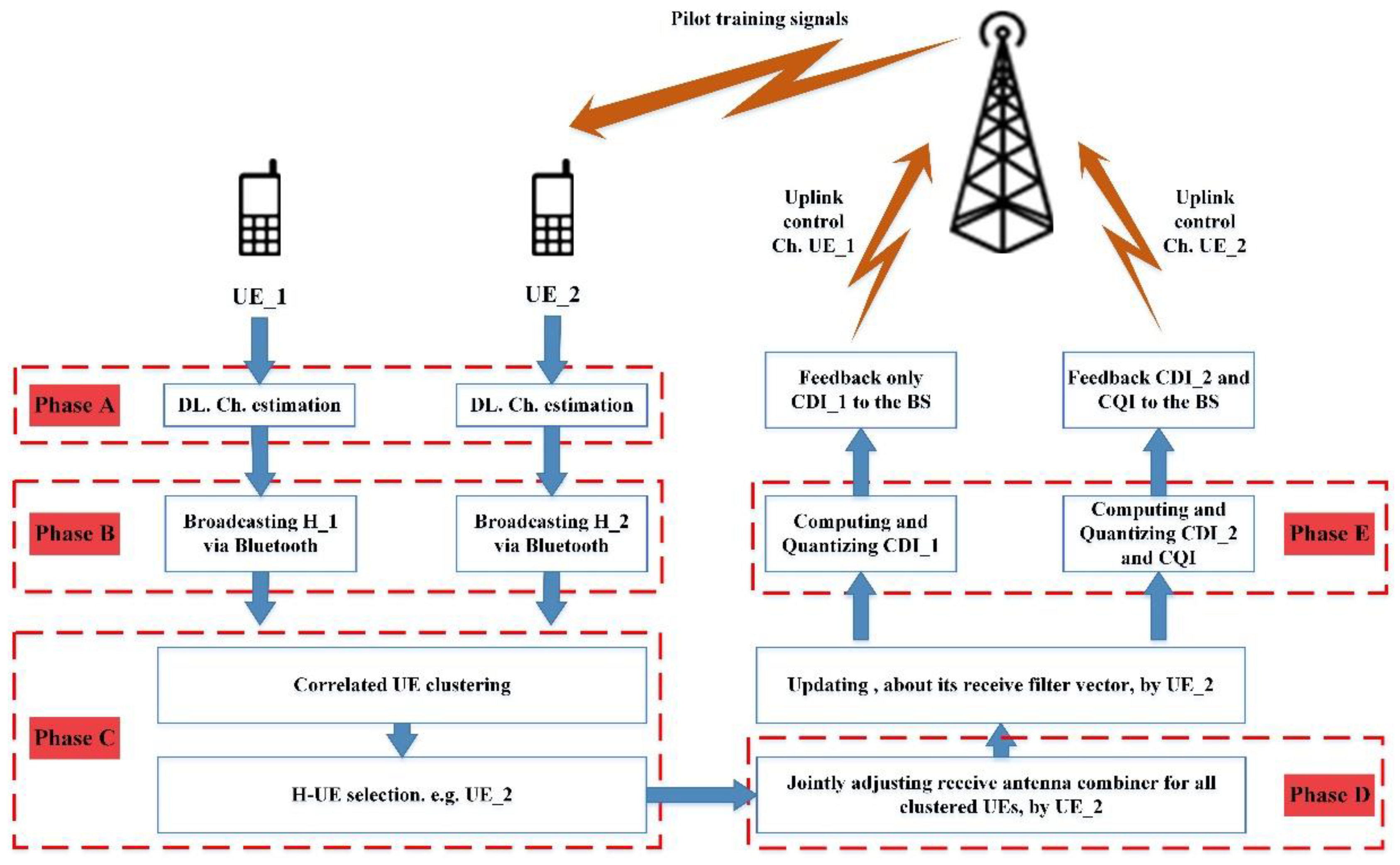
Figure 1 visualizes the proposed strategy.
The UCIC strategy is developed based on the proximity of UE. In UCIC, vicinity UE cooperates in canceling the interferences. First, each piece of UE estimates its downlink channel, then by utilizing an unlicensed frequency band, broadcasts its estimated channel to share with other active UE that is located in its vicinity. In the next step, UE located close to other UEs that experiences roughly the same channel characteristics, is grouped into a cluster. In each group, a piece of UE is selected as the Head of clustered UE (H-UE). Then, H-UE by having knowledge of its cluster mates’ CSI, starts to jointly adjust receive antenna combiner weight vectors of itself and its cluster mates. Then, only H-UE of each cluster feeds back the mutual CSI (CQI) to the BS. Therefore, instead of feeding back CSI by each piece of UE individually, only H-UE feeds back the mutual CSI, and other UE only feeds back its CDI, which consequently results in a lower CSI feedback overhead. Finally, the CSI feedback information at the BS is utilized for canceling the residual interference between pieces of UE, as well as UE scheduling, power, and resource allocation, adjusting MIMO mode, and modulation and coding scheme. The following describes different phases of the developed strategy in more detail.
3.1. Downlink Channel Estimation
As the first phase, each piece of UE individually estimates its desired downlink channel. To do so, the Minimum Mean Squared Error (MMSE) channel estimation technique is utilized. The downlink channel estimation is learned through known pilots that are transmitted by the BS. The training sequence can be denoted as
, where
for
, and the training sequence is normalized as
. The received training signal at user
is
where
is the average transmit power during the pilot training period. By applying the conjugate-complex matrix of
to (7), the observed channel can be written as
where
is pilot training, and
is noise during pilot training. By applying the MMSE scheme to (8), the channel can be estimated as
and
where
is the estimated channel of
user, and
is the Eigenspace representation of the channel matrix. For more details about the channel estimation, readers are referred to [
29].
3.2. CSI Broadcasting
After each piece of UE estimates its desired downlink channel, it is time for the UE to share its knowledge of the estimated channel with other activated UE. For this purpose, UE can utilize an unlicensed frequency band and broadcast its based on D2D short-range communication.
3.3. Correlated UE Clustering and H-UE Selection
In this stage, thanks to the broadcasting, UE can identify of other UE in its vicinity. Generally, this knowledge can be categorized into two groups: (i) knowledge about large-scale fading, and (ii) knowledge about small-scale fading. It is known that small scale fading is uncorrelated between the components of the channel matrix, while it can be assumed that proximate UE can experience correlated large scale fading between pieces of equipment, such as path loss and shadow fading. Thus, it can be assumed that CQI can be almost similar between adjacent UE. Therefore, correlated UE can be grouped into one cluster.
For UE clustering, the K-means clustering algorithm is utilized, which partitions UE into different groups based on the similarity of its channel covariance matrices. To do so, the coefficients of the Rayleigh channel matrix is considered as
, where coefficients are mutually independent across the pieces of UE, and
is given as
where
is a
matrix of the eigenvectors that correspond to the
non-zero eigenvalues of
and
is a diagonal
matrix composed of the non-zero eigenvalues of
. The Karhunen–Loeve representation of
is given as
where the entries of
are i.i.d.
. The K-means algorithm uses the chordal distance between the covariance eigenspaces—i.e.,
, as
where
is the mean of
unitary matrices, as
where
[X] is the unitary matrix formed by the
p dominant eigenvectors of X. The pseudo-code of the clustering decision making process is presented in Algorithm 1.
| Algorithm 1: Correlated UE Clustering Algorithm |
| INPUT: Eigenvectors of the covariance matrix , for |
| OUTPUT: Clusters of correlated UE |
|
PROCEDURE: |
| for every subframe of length TTI perform |
| Step 1: Compute according to (13) for every and |
| Step 2: Assign correlated UE into similar groups |
| Step 3: Update in (14) |
| Step 4: Randomly select a UE as H-UE |
| end for |
3.4. Jointly Adjusting Receive Antenna Combiner Weight Vector
At this stage, it is time for jointly computing and adjusting receive antenna combiner weight vectors,
. To do so, first, H-UE computes its receive antenna combiner weight vectors,
based on the MET technique [
30], to maximize its effective channel gain as
where
can be found by considering the Single Value Decomposition (SVD) form of
, as
where it is assumed that the singular values
on the main diagonal of
are stored in decreasing order. The receiver antenna combining weight vector of H-UE,
is given as
where
denotes the left singular vector corresponding to the maximum singular value of
. Afterward, the H-UE by knowing its group mates’ channel, starts to jointly compute and adjust the
for other clustered UE as
According to (20), H-UE computes the
of its group mates, in such a way to be orthogonal with its effective channel, by projecting its effective channel to the effective channel of UE
k. It should be noted that to compute CDI, the knowledge of effective channel direction,
is needed, which can be computed as
where
is the effective channel vector, and it is a concatenation of channel matrix and receive filter, as
It should be noted that contains essential channel statistics for residual interference cancellation at the BS; hence, the design criteria of receive filter play an important role in enhancing system performance. Additionally, it is well known that adjacent pieces of UE are the main victim of inter-user interference. Therefore, by jointly adjusting the receive antennas’ combiner vectors, more useful CDI can be fed back to the BS, for both inter-user interference and inter-sector interference cancellation.
3.5. CSI Computation, Quantization, and Feedback
As described earlier, only H-UE computes its own CQI, based on the expected value of SINR, as
where
is the assigned transmission power to H-UE, and
is the angle between effective channel direction and quantized channel direction.
The H-UE computes and adjusts the receive antenna combiner vector for itself, as well as its group mates. Hence, H-UE must update its group mates about their
, where it can be performed by broadcasting
via the same broadcasting procedure described in phase B. Afterward, each piece of UE knows its own
, and, therefore, starts to compute its effective channel direction according to (22), as well as CDI as
where
is a quantization function. For this purpose, the Random Vector Quantization (RVQ) method [
31] is utilized, which is known for its advantages in CSI comparison. After this, each piece of UE individually feeds back its CDI to the BS.
3.6. Base Station Procedures
BS utilizes the received CDIs of all participating pieces of UE to compute the precoder matrix. In this regard, the ZF precoder is utilized, which can be computed as
The design criteria of ZF precoder is based on the orthogonalization of quantized effective channel vectors of UE, as , where . Moreover, BS utilizes the CQIs of H-UE for UE scheduling, resource allocation and modulation, and coding rate adaptation.
4. Simulation Setup
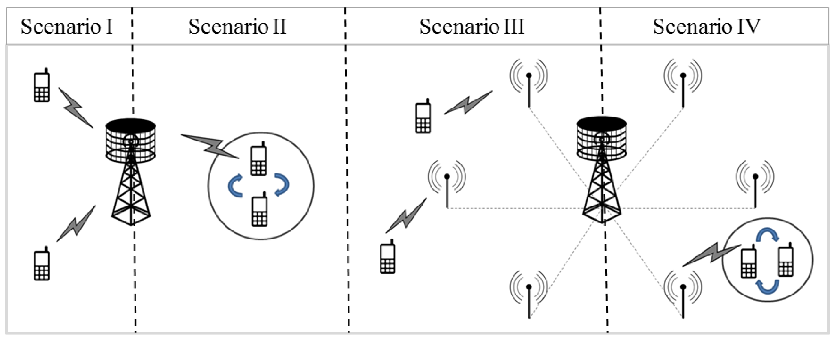
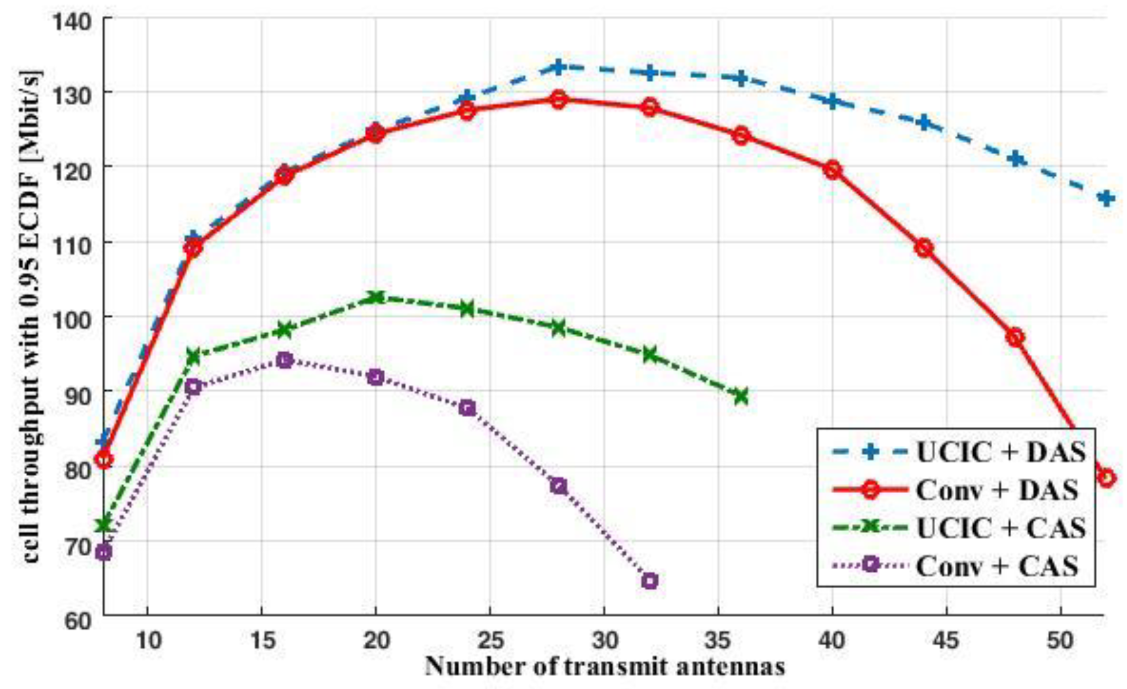
To evaluate the performance of the developed UCIC strategy, four scenarios are considered for the simulation, as:
Scenario I: Large-scale MIMO downlink transmission with the conventional limited feedback technique and CAS configuration, termed as Conv + CAS.
Scenario II: Large-scale MIMO downlink transmission with UCIC strategy and CAS configuration, termed as UCIC + CAS.
Scenario III: Large-scale MIMO downlink transmission with conventional limited feedback technique and DAS configuration, termed as Conv + DAS.
Scenario IV: Large-scale MIMO downlink transmission with UCIC strategy and DAS configuration, termed as UCIC + DAS.
In
Figure 2, the four scenarios mentioned above are visualized. A single-cell multi-user simulation scenario is considered, where one BS with a hexagonal grid architecture is employed, and out-of-cell interference is ignored. Generally, six users are distributed over the entire cell area, each of which is equipped with two antennas. In scenarios with DAS architecture (Scenario III and IV), the central BS is covered with
R uniformly distributed Radio Remote Units (RRUs), which are located equiangularly on a ring with a radius of
. The total number of transmit antennas is uniformly distributed among the central BS and RRUs. For more details about the DAS architecture, readers are referred to [
31,
32].
The results are based on the link-level simulation, where PHY procedures of single-cell multi-user scenarios are considered. For this purpose, version 1.3 of the Vienna link-level simulator [
33] is used. Notice that the precoder and codebook quantization methods, which are used in the simulator, are based on the LTE and LTE-A specifications. Thus, in the simulations, the scale of the considered MIMO system is limited to 52 antennas. That is because by increasing the number of transmit antennas, the computation complexity of the codebook will increase dramatically, which consequently results in an unreasonable simulation run time.
Table 1 presents simulation parameters under consideration.
At the transmitter, a greedy scheduler algorithm [
28] is employed to assign resource blocks to the users. The scheduling decision is made according to the CQI feedback in (23). The ZF precoding technique, as described in 3.6, is employed at the transmitter side. The precoder uses the CDI feedback in (24) to compute the precoding matrix. The signaling transmission is assumed to be error-free.
To model the channel, a narrow-band multi-scattering directional channel model [
34] is used, as
where
is the number of paths,
is the complex-valued amplitude of pth path,
and
are the antenna array response vectors at the transmitter and receiver, respectively.
and
are the azimuth and elevation angles at the transmitter and receiver, respectively.
In a large-scale MIMO system, the number of transmit antennas is much larger than the number of paths; therefore, when grows large, the considered channel can be represented as a Rayleigh fading model. Therefore, the CDI feedback of one subcarrier is adequate to set the same precoder for the whole bandwidth. The temporal evolution of the small-scale channel matrix is determined by a correlated block-fading model, and the channel is assumed to be invariable during the subframe interval of 1 ms. Hence, the period of the CSI feedback is set as 1 ms.
A two-dimensional horizontally aligned uniform linear antenna array (ULA) is utilized in simulation, where the array response vector can be represented as
where
is the complex-valued antenna-element gain pattern,
is the inter antenna-element spacing in multiples of the wavelength
. In the simulation, it is assumed that
,
, and
is uniformly distributed,
. For more details about the channel modeling and the antenna specification, readers are referred to [
15].
To achieve the throughput, the achievable mutual information introduced in [
33] is used as
where
is the total number of usable subcarriers,
is the set of precoding matrices,
is an identity matrix of size N, and
is the energy of the noise and interference at the receiver.
is the bandwidth of a subcarrier and Z is a factor of the system losses due to the transmission of the reference symbols and the cyclic prefix.


