Research on the Optimal Operation Method of DC Microgrid Base on the New DC Power Distribution Management System


1
Department of Electrical Engineering, Tsinghua University, Haidian, Beijing 100084, China
2
Department of Electric Power Engineering, Shanghai University of Electric Power, Yangpu, Shanghai 200090, China
*
Authors to whom correspondence should be addressed.
Electronics 2020, 9(1), 9; https://doi.org/10.3390/electronics9010009
Submission received: 15 November 2019
/
Revised: 7 December 2019
/
Accepted: 8 December 2019
/
Published: 20 December 2019
(This article belongs to the Section Electrical and Autonomous Vehicles)
Abstract
:The grid-connected operation of the distributed generation (DG) via the direct current (DC) microgrid is the operation mode of the DC power distribution system in the future. Considering the grid-connected operation of multiple DC microgrids, we have proposed a new type of DC power distribution management system aiming at the lowest operating cost of the entire DC power distribution system. Our proposed DC power distribution management system can be used to carry out the optimized dispatching for the connected DC microgrids, thereby achieving the economic, safe, and stable operation of DC power distribution management systems. At the same time, through the different nodes where the modular multilevel converter (MMC) is connected to the alternating current (AC) distribution network, a DC power distribution management system can control the active and reactive power generated by the MMC, achieving the control of the load flow of the upper-stage AC grids in real time. The example simulation shows that the method proposed in this paper has a great role in reducing the transmission losses of the power distribution network, achieving electric power peak-load shifting, and utilizing renewable energy. Thus, it can not only maximize the use of distributed renewable resources, but also enable mutual support and optimal scheduling between a DC power distribution system and multiple microgrids.
1. Introduction
The direct current (DC) power distribution network has excellent performances regarding large transmission capacity, low transmission loss rate, low cable cost, high power supply quality, and flexible and friendly connection of distributed generation; this is the development direction of the power distribution system in the future. Microgrid technology represents the development trend of distributed generation supply systems in the future, and is an important part of future intelligent power distribution systems [1]. Meanwhile, most of the energy generated by distributed generation (DG) such as photovoltaics (PV), wind turbine (WT), microturbine (MT), and battery-type energy storage (BES) units is of DC or non-power frequency alternating current (AC) electricity; therefore, the connection of DG to the DC microgrids will save a lot of converter links, achieving the reduction of costs and losses simultaneously. The DC bus voltage is the only standard to measure the active power balance in the system where the problems of frequency stability and reactive power inherent in the AC system are absent. The DC microgrids can also be connected in parallel with the existing AC microgrids or power distribution network through bidirectional DC–AC converters, and can effectively isolate the AC side disturbance or fault, which can ensure the highly reliable power supply of the load in the DC system [2,3]. In addition, with the development of energy storage, it can better play the role of suppressing the impact of the voltage transient process, which makes the voltage of the DC microgrids more stable [4,5]. It can be clearly seen that the grid-connected operation of the DG via the DC microgrid will be the main operation mode of the future DC power distribution systems [6].
At present, the DC power distribution system has gradually been focused on by scholars at home and abroad. The concept of using a DC network connection to improve the power processing capability of the power distribution network was proposed [7]. The existence and uniqueness of the load flow solution of the DC power distribution system under different control modes was firstly proved, and the analysis method for voltage stability based on the feasible solution was simultaneously proposed [8]. The flexible DC power distribution network was analyzed from the aspect of the random load flow, and the source-load response strategy was proposed by considering the system operation cost as well as the voltage off-normal probability [9]. The operation status of the flexible DC distribution network was evaluated, and a scheduling control strategy based on the comprehensive evaluation of the node power and voltage was proposed [10].
By employing the operation control and optimized scheduling technologies of distributed DC microgrids, a variety of distributed resources are integrated, and the DC power distribution systems are centrally connected to the main electric network through some power electronic devices. Each DC power distribution system that is connected to the main network operates in a complementary and coordinated manner, which can not only partially reduce the cost of the AC/DC converters, but also achieve the economic operation of the power grid, thereby improving the power quality and power supply reliability. In Reference [11], a model taking into account the cost of electric power peak-load shifting, microgrid configuration cost, and expected customer interruption cost as the objective functions was established, and the distribution system model where multiple microgrids are connected was solved based on coordinating the game model evolution algorithm. In Reference [12], the output power and input power of the microgrid to the distribution network were used as the upper and lower limits of the microgrid interactive power, the economic and optimized active power scheduling model of the distribution network was established, and the solution to the model based on maximum flow calculation method was proposed. In Reference [13], hierarchical scheduling, distributed optimization theory, and a method based on analysis of the target cascading were used to optimize the scheduling of AC/DC hybrid active distribution networks with multiple types of DG.
In the future, the power system will gradually develop an AC/DC hybrid smart system where multiple DC microgrids are integrated into a large grid operation by flexible interconnections [14]. To this end, this work has firstly proposed a DC power distribution management system that flexibly interconnects multiple DC microgrids. Within the DC power distribution management system, the microgrids are connected to the DC power distribution management system for interconnection through power electronic devices, thereby optimizing the scheduling of each microgrid. Then, the interrelationship between the DC power distribution management system and the large power grid after connecting the DC power distribution management system to the large power grid has been considered, and an optimal scheduling strategy for the entire power grid has been proposed by using the DC power distribution management system and the flexible transmission and distribution equipment.
The DC power distribution management system is used to manage multiple DC microgrids; it can not only maximize the use of distributed renewable resources, but it can also enable mutual support and optimal scheduling between the DC power distribution system and multiple microgrids. Thus, the whole system can run stably and efficiently.
2. DC Power Distribution Management System
In Figure 1, DC microgrids are connected to DG such as PV, WT, MT, BES, and load (demand response and conventional load), and then connected to the DC power distribution management system via DC/DC converters, while the DC power distribution system is connected to the AC distribution network through the modular multilevel converter (MMC). In the operating mode of connecting to the DC power distribution management system, the integrated controller of each DC microgrid is responsible for local optimized operation control, and each microgrid supports each other through communication and control. The DC power distribution management system maintains the DC bus voltage balance by coordinating and managing the MMC to achieve the stability of the whole system, and it simultaneously collects the data of the MMC, which connects the main network to the DC microgrids and distributes the transmission power of each MMC to implement real-time optimization of the load flow of the main network.
2.1. The Operating Goal of the DC Power Distribution Management System
The operating goal of the DC power distribution management system lies in its lowest economic cost:
where the operating cost mainly consists of two parts. One is the total cost of each microgrid dispatching CMG, which is calculated with Equation (2). The other is CMMC; the DC power distribution management system purchases electricity from the upper-stage power grid through MMC (including MMC loss cost), which is calculated with Equation (3).
(t) stands for the active loss for g-th MMC, and can be expressed as follows:
2.2. Distributed Energy Sources Output Model
As can be seen from Figure 1, the distributed energy in the microgrid is mainly PV and MT. During the optimized operation of the DC power distribution management system, due to the dispersion and small capacity for a single unit, the distributed PV adopts the maximum power point tracking (MPPT) control from the angles of reducing the installation cost of the communication equipment and reducing the complexity of the system.
MT has the characteristics of fast response, which can effectively suppress the fluctuation of renewable energy sources output. The mathematical model of MT is as follows:
where Equation (8) is the ramping-rate constraints for MT, which indicates respectively the downward and upward maximum ramping rate of the generator.
2.3. BES Model
The DC power distribution management system proposed in this work can improve the grid-connection capability of DG and make full use of renewable energy; the energy storage device BES is set up:
In Equation (9), the first and the second formula represent the power limit of charge and discharge of energy storage. The introduction of the constraint that BES can only be in one of three states of charging, discharging, and neither-charging-nor-discharging at any moment, while the physical infeasible state of charging-whilst-discharging is excluded. The total power is the sum of charging power and discharging power.
2.4. Demand Response Model
The response from the demand side can flexibly adjust the load characteristics to meet the system operating conditions [15]:
where the first subequation is the demand-side response of actual power extraction from 0–1; the second subequation is the demand-side response of the minimum up-time constraints for load curtailment; and the third subequation is the maximum up-time constraints for curtailment-enabled load.
3. Dynamic Optimal Load Flow Model of AC Distribution Network
Via the real-time control of the DC power distribution management system, not only can each DC microgrid at the bottom layer be optimally scheduled, but also the interchange power between the DC power distribution management system and the AC distribution network can be distributed by utilizing MMC, thereby changing the active/reactive power of the distribution network node connected to the MMC; at the same, via the mutual coordination of the DC power distribution management system with the static var compensator (SVC), the load flow of the AC distribution network can be controlled, thereby achieving the coordination and optimization of the whole system.
The optimization goal for the AC power distribution network is to minimize the transmission losses cost of the distribution network during the whole scheduling period:
In addition to using the DC power distribution management system to carry out load flow optimization, this work has also considered the real-time control of the AC distribution network load flow by using SVC.
Due to the connection of the high-permeability renewable energy sources, the load flow may be reversed when the load is low, resulting in the problem of over-voltage. The traditional pure capacitive compensation method should also be properly adjusted. Therefore, it is necessary to set the SVC in the AC distribution network.
The AC distribution network must also meet the load flow constraints during operation [16], system safety operation constraints, and root node power limits:
Equations (13) and (14) are the power flow constraints of the distribution network; Equation (15) is the line current constraint and node voltage constraint; Equation (16) is the active and reactive power constraints of the root node of the distribution network.
4. Case Studies
In our numerical simulation example here, the DC power distribution management system shown in Figure 1 has been used, while the AC distribution network has been chosen to be the IEEE33 node radial distribution network in Reference [16], which then has been improved in our work. As shown in Figure 2, via the MMC, the DC power distribution systems are connected to nodes 7, 13, and 24 of the AC distribution network (MMC7, MMC13, and MMC24); the scheduling period is 24 h, and the optimized instruction cycle is 15 min. The PV predicted data comes from the power curve of a PV power plant; the load data of each node separately use the bus load data measured by the Biling substation on a certain day in December. In order to demonstrate the role of the DC power distribution management system in utilizing the DG, the centralized wind farms (WT18, WT31) are connected at node 18 and node 31 with a power factor of 0.9; the predicted data for wind power is derived from the power curve of a wind farm. For the convenience of analysis, and taking into account of the fact that the cover area of the whole distribution system is not large, the same load curve is adopted for all load nodes, the same illumination curve is adopted for PV, and the same wind speed curve is adopted for the wind power, load standard value curve, and illumination standard. The per-unit value curves for load, illumination, and wind speed are all shown in Figure 3. The SVC is connected to nodes 5 and 22 (SVC5, SVC22), and the reactive power compensation power range is from −300 kvar to 300 kvar, and the configuration for DC microgrids in the DC power distribution management system is shown in Table 1.
In addition, the electricity price is ¥0.67/kW·h, the MT operating cost is ¥0.5/kW·h, the demand side response compensation is ¥1.1/kW·h; the state of charge (SOC) upper and lower limits of BES are 5% and 95%, the BES charge and discharge efficiency is 93.81%, the maximum number of charges and discharges is 1.5, the BES storage capacity accounts for 10% of the maximum capacity at the beginning of the scheduling period; the maximum ramping rates for MT in MG1, MG2, and MG3 are respectively 60 kW/h 40 kW/h, and 80 kW/h; the demand-side response period is 18:00 to 23:00, the minimum up-time is 0.5 h, the maximum up-time is 2 h; the MMC capacities are 120 kW, 150 kW, and 80 kW, respectively; the loss factor is 0.05; the upper and lower limits of the interchange active power between the AC distribution network and the upper-level grid are 2500 kW and 1600 kW, respectively.
After optimized scheduling, the total cost of the entire power distribution system is ¥33,273, of which MG1 costs ¥665.7, MG2 costs ¥1021.2, MG3 costs ¥319.1, the MMC loss costs ¥105.1, and the network losses cost ¥249.1.
The optimization results of DC microgrid 1 are shown in Figure 4, the ctive output for centralized wind farms is shown in Figure 5 and the active power of AC side of MMCs is shown in Figure 6.
It can be seen from Figure 4, Figure 5 and Figure 6 that during the period of 0:00–7:00, the load is at a low value and is influenced by the power limitation of the distribution/transformation gateway. Meanwhile, the centralized wind farm stops generating electricity, and the gas turbine in the microgrid (taking microgrid 1 as an example) does not generate electricity at the same time. In addition, the battery BES begins to charge to utilize the distributed renewable energy in the DC microgrids, which can alleviate the impact of the power fluctuation of the distribution/transformation gateway on the upper transmission network. Due to the small DG output of each microgrid, the DC power distribution management system absorbs power from the AC distribution network to meet the load requirements of each microgrid. The MMC24 always absorbs power from the root node with maximum power. In fact, in order to avoid the situation where the DC power distribution management system absorbs power from the MMC farther from the root node, reduce unnecessary network loss caused by lower node voltages, improve the voltage quality, and shorten the distance of the power flow, the MMCs close to the root node are needed to absorb the electric energy as much as possible. When the active power absorbed by the MMC 24 reaches the capacity, the remaining power is absorbed by the MMC7 and MMC13 to meet the load demand of the DC power distribution management system.
The transmission losses of the power distribution network are shown in Figure 7. After 8:00, the interchange power between the root node of the distribution network and the upper power grid is always within the safe operating range, and the operating cost of the controllable DG (MT) is lower than the electricity price purchased from the grid. The MT in the microgrid is maintained to be at the maximum output state, thereby reducing the operating cost of the entire system; centralized wind farms also operate in the maximum power point tracking (MPPT) state, utilizing the renewable energy to the maximum extent.
During the period of 9:00–16:00, the DG output of DC microgrids will enter the peak period, which can not only meet the power demand of the load in the microgrid, but also can achieve the power transmission to the other nodes of the AC distribution network. Since the MMC 13 is located at the end of the longest branch circuit, if it is used to directly supply power to the rest of the branch circuits, the branch circuit congestion and node overvoltage caused by long-distance power transmission from the far root node can be avoided, thereby reducing the line loss. At some time in 12:00–14:00, the output of the renewable power in each DC microgrid is almost at the maximum state. The output energy of the MMC13 alone cannot completely utilize the DG in the microgrid, so the MMC7 that is farther from the root also begins to output active power to the AC distribution network, which can meet the load requirements of other nodes in nearby branch circuits. From 12:00 to 13:00, the output power of the WT18 reaches the maximum value, which can fully meet the load requirement of the remaining nodes on the branch circuits. Therefore, the active power generated by MMC13 that is close to and in the same branch circuit as WT18 is reduced. The DC power distribution management system supplies power to the load of the other branch circuit through the MMC7, showing the flexibility and superiority of the DC power distribution management system proposed in this paper in the process of utilizing renewable energy.
During the whole scheduling period, SVC performs the maximum capacitive reactive power compensation to reduce the line loss as much as possible. Due to the optimal scheduling of each controllable resource, constrained operation of the DC power distribution system can be fully achieved most of the time, and the controllable load is only slightly reduced around 19:00.
If the DC microgrids are not integrated into the DC distribution management system to implement the centralized management, direct control over them cannot be achieved due to the dispersion of DG. The MT is planned to produce electricity in full power during 8:00–22:00; the BES is planned to charge during 9:00–14:00 and to discharge during 17:00–22:00; each DC microgrid is connected to the AC grid at node 7, node 13, and node 24.
For the case where MG1 (node 7), MG2 (node 13), and MG3 (node 24) are directly connected to the AC distribution network, the absence of a DC power distribution management system that carries out the scheduling of each DC microgrid and DG can lead to phenomenon whereby the active power of the root node exceeds the operational limit (Figure 8), and the root node power fluctuations have an adverse effect on the operation of the upper transmission network. The DC power distribution management system proposed in this work can avoid excessive active and reactive power input from the root node, thereby reducing reactive long-distance transmission and effectively preventing line overload.
In addition, in the absence of the centralized coordination and control of a DC power distribution management system over the interchange power between DC microgrids and the distribution network, it is impossible to effectively optimize in real time the load flow in the power distribution network, leading to the serious congestion of the lines, and raising the transmission losses cost up to ¥327.4, which is 31.4% higher than the power distribution network under the coordination and optimization of the DC power distribution management system. So, it can be clearly seen that the DC power distribution management system used for real-time control over load flow plays a great role in reducing the transmission losses of the power distribution network.
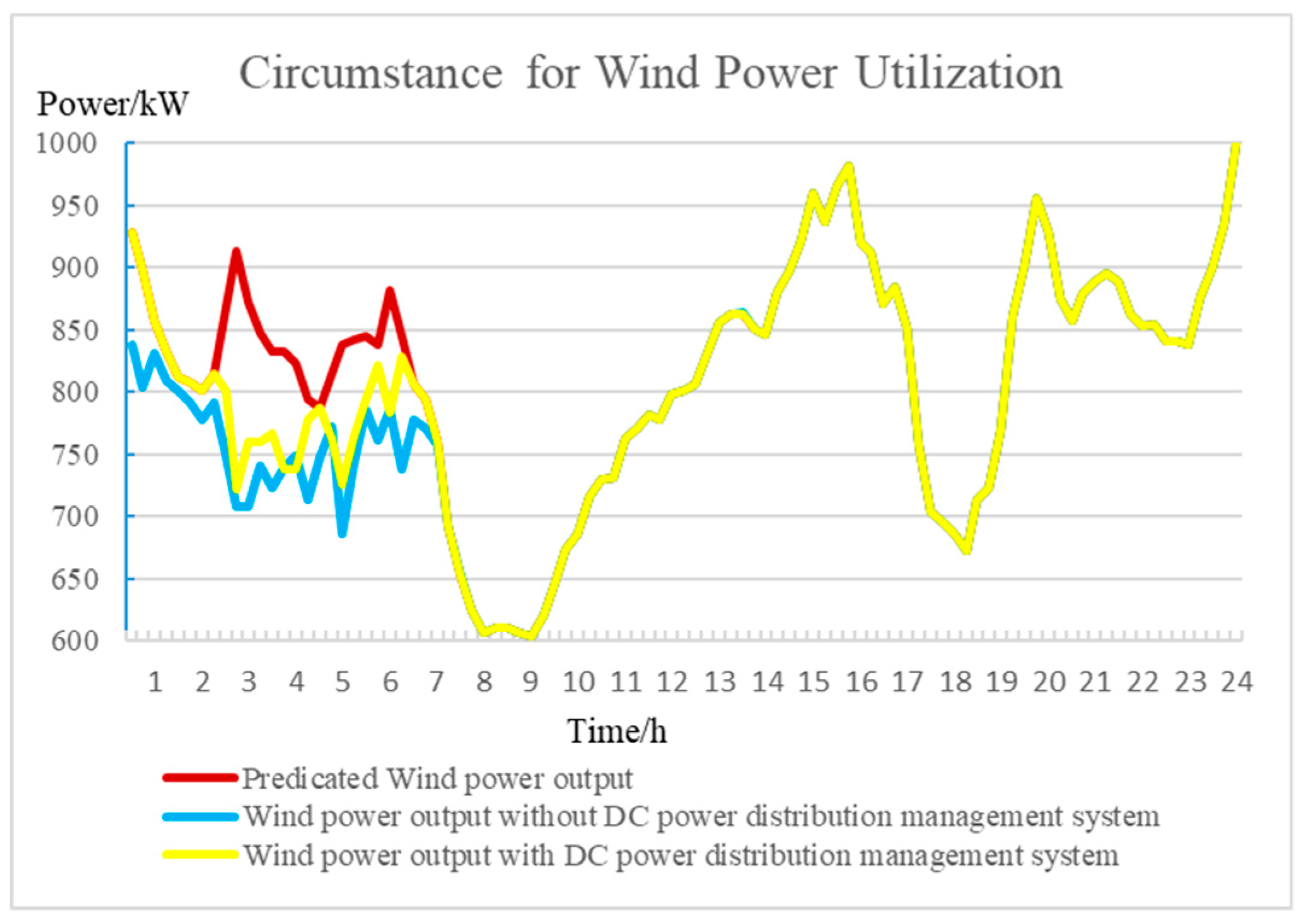
In order to study the role of the DC power distribution management system designed in this work in the utilization of renewable energies, the permeability of centralized wind farms is now increased, the installed capacity of centralized wind farms (WT18, WT31) is increased to 1000 kW, and the generated output for the power distribution system WT18 is shown in Figure 9:
It can be seen from Figure 9 that the electric load is small while the predicted output of the wind power is still large during the period from 1:00 to 5:00, and the power that can be stored in BES in each DC microgrid is limited. Under the security constraints such as the branch circuits’ currents and nodes’ voltages, a large amount of renewable energy is forced to be abandoned. However, in the presence of a DC power distribution system for optimal scheduling (eliminating overvoltage and preventing branch circuit congestion), it is possible to nearly utilize more than 250 kW·h of electricity. Therefore, the example has shown that the DC power distribution management system proposed in this work can play a greater role in utilizing renewable energies.
However, this paper considers the distribution network and each microgrid as a whole without considering the interests of each microgrid itself. In fact, each microgrid may be different stakeholders. Therefore, how to realize the optimal distribution of benefits among various subjects is the future research direction.
5. Conclusions
With the grid connection of a large number of DGs, DC microgrids are integrated into the major power grid; as a result, the motivation of this work is how to achieve the energy management of the power distribution system and reduce the impact caused by the high permeability of renewable energies, thereby improving resource utilization as much as possible.
- The architecture and model of the DC power distribution management system have been established to coordinate the dispersive DC microgrids in real time, optimize the scheduling of DG, and achieve the economic operation of the DC power distribution management system.
- The DC power distribution management system that can carry out the unified allocation of the interchange power between all the DC microgrids and the AC distribution networks, together with the reactive power compensation equipment SVC, has been used to achieve load flow optimization of the power distribution network. The method proposed in this paper can effectively reduce the power distribution network loss.
- As far as the utilization of renewable energies is concerned, the real-time optimization control via the DC power distribution management system can effectively avoid a series of problems caused by fluctuations in the output of renewable energies, greatly reducing the level of wind abandonment in centralized wind farms.
Author Contributions
The article conceptualization, Z.Y. and L.Q.; methodology, Q.P.; software, Q.P., B.O., and P.G.; writing—original draft preparation, Q.P. and B.O.; writing—review and editing, Z.Y., Q.P., and B.O. All authors have read and agreed to the published version of the manuscript.
Funding
This research was funded by Ministry of industry and information technology of the People’s Republic of China.
Acknowledgments
The authors gratefully acknowledge the financial support by the National Key Research and Development Program 2017YFB0903204.
Conflicts of Interest
The authors declare no conflict of interest.
Nomenclature
| Abbreviations | |
| DC | direct current |
| MMC | modular multilevel converter |
| AC | alternating current |
| PV | photovoltaics |
| WT | wind turbine |
| MT | Micro-turbine |
| DG | distributed generation |
| BES | battery-type energy storage |
| MPPT | maximum power point tracking |
| Parameters and Variables | |
| CMG | total cost of each microgrid dispatching |
| CMMC | DC power distribution management system purchases electricity from the upper stage power grid through MMC (including MMC loss cost) |
| number of the DC microgrids | |
| n | number of MMC |
| L | number of unit periods based on the complete scheduling period |
| electricity price at time t | |
| cDG | unit operating cost for the DG (here mainly refers to the operating costs of controllable DG) (MT) |
| actual active power of controllable DG in k-th DC microgrid at time t | |
| ccut | unit cost cutting for controlled load. |
| actual active power extraction of the controllable load in the k-th DC microgrid | |
| transmission power of the g-th MMC at time t (it is positive for the flowing from the distribution network into the DC power distribution management system, and negative otherwise) | |
| active loss for g-th MMC | |
| loss coefficient of MMC | |
| AC-side active power of MMC in the g-th node of the distribution network at time t | |
| AC-side reactive power of MMC in the g-th node of the distribution network at time t | |
| DC-side active power of MMC in the g-th node of the distribution network at time t | |
| predicted power of PV power in the k-th DC microgrid at time t | |
| PMT | capacity of the micro gas turbine in the k-th DC microgrid |
| limit of climbing speed | |
| discharge power of BES in the k-th DC microgrid at time t | |
| charge power of BES in the k-th DC microgrid at time t | |
| maximum discharge power of BES in the k-th DC microgrid at time t | |
| maximum charging power of BES in the k-th DC microgrid at time t | |
| state variable of BES discharge in the k-th DC microgrid at time t | |
| state variable of BES discharge in the k-th DC microgrid at time t | |
| demand-side response of operation state of the controllable load in the k-th DC microgrid at time t | |
| * | maximum power extraction of the curtailment-enabled load in k-th DC microgrid |
| minimum up-time of load curtailment | |
| maximum up-time for load curtailment. | |
| Ui(t) | voltages of i-th and j-th node at time t |
| yij | admittance between i-th and j-th node |
| upper limits of the SVC adjustable reactive power connected to the i-th node. | |
| lower limits of the SVC adjustable reactive power connected to the i-th node. | |
| u(j) | the set of the head end nodes of the branch circuit with the j as the end node in the distribution network |
| v(j) | the set of the end nodes of the branch circuit with the j as the head end node in the distribution network |
| Pij(t) | active power at the head end of the branch circuit ij at time t |
| Qij(t) | reactive power at the head end of the branch circuit ij at time t |
| Pj(t) | net injection values of active power of node j at time |
| Qj(t) | net injection values of reactive power of node j at time |
| Iij(t) | current amplitude of branch circuit ij at time t |
| Qj(t) | active power sent by the upper power generator on node i |
| rij | resistance of the branch circuit ij |
| xij | reactance of the branch circuit ij |
| upper limits of the voltage amplitude of the node i | |
| lower limits of the voltage amplitude of the node i | |
| upper limit of the amplitude of the current of the branch circuit ij; | |
| P0(t) | active power flowing from the root node to the AC distribution network at time t |
| Q0(t) | reactive power flowing from the root node to the AC distribution network at time t |
| upper limits of the active power of the root node gateway of the AC distribution network | |
| lower limits of the active power of the root node gateway of the AC distribution network | |
| upper limits of the reactive power of the root node gateway of the AC distribution network | |
| lower limits of the reactive power of the root node gateway of the AC distribution network | |
References
- Li, X.; Guo, L.; Wang, C.; Li, Y. Key technologies of DC microgrids: An overview. Proc. CSEE 2016, 36, 2–17. [Google Scholar]
- Jiang, D.; Zheng, H. Research status and developing prospect of DC distribution network. Autom. Electr. Power Syst 2012, 36, 98–104. (In Chinese) [Google Scholar]
- Dragicevic, T.; Vasquez, J.C.; Guerrero, J.M.; Skrlec, D. Advanced LVDC electrical power architectures and microgrids: A step toward a new generation of power distribution networks. IEEE Electrif. Mag. 2014, 2, 54–65. [Google Scholar] [CrossRef] [Green Version]
- Xiangjun, L.; Shangxing, W.A.; Dong, H. Summary and prospect of operation control and application method for battery energy storage systems. Power Syst. Technol. 2017, 41, 3315–3325. [Google Scholar]
- Jichen, L.; Ma, H.; Hui, D. Present development condition and trends of energy storage technology in the integration of distributed renewable energy. Trans. China Electrotech. Soc. 2016, 31, 1–10. [Google Scholar]
- Song, Q.; Zhao, B.; Liu, W.; Zeng, R. An overview of research on smart dc distribution power network. Proc. CSEE 2013, 33, 9–20. (In Chinese) [Google Scholar]
- Chaudhary, S.K.; Guerrero, J.M.; Teodorescu, R. Enhancing the Capacity of the AC Distribution System Using DC Interlinks—A Step Toward Future DC Grid. IEEE Trans. Smart Grid. 2015, 6, 1722–1729. [Google Scholar] [CrossRef]
- Zhang, C.; Peng, K.; Xu, B.; Chen, Y.; Zhao, Y.; Zhao, Y. Feasible power flow solution and voltage stability analysis method for DC distribution system. Autom. Electr. Power Syst. 2018, 42, 48–53. [Google Scholar]
- Huang, J.; Wei, C.; Wen, A. Hierarchical coordinated control strategy for flexible DC distribution network considering uncertainties of source and load. Autom. Electr. Power Syst. 2018, 42, 101–112. [Google Scholar]
- Xie, D.; Chen, A.; Yu, S.; Lu, Y.; Gu, C.; Li, Y. Research on Synthetic Scheduling Index and Scheduling Strategy of Multiport Flexible DC Distribution Network with Droop-control. Proc. CSEE 2019, 10, 1–10. (In Chinese) [Google Scholar]
- XU, Y.; AI, Q. Coordinated optimal dispatch of active distribution network with microgrids. Electr. Power Autom. Equip. 2016, 36, 18–26. [Google Scholar]
- Zhang, X.; Niui, H.; Zjao, J. Optimal dispatch method of distribution network with microgrid. Trans. China Electrotech. Soc 2017, 32, 165–173. (In Chinese) [Google Scholar]
- Qi, C.; Wang, K.; Li, G.; Han, B.; Xu, S.; Wei, Z. Hierarchical and Distributed Optimal Schedulin of AC/DC Hybrid Active Distribution Network. Proc. CSEE 2017, 37, 1909–1917. (In Chinese) [Google Scholar]
- Ma, Z.; Zhou, X.; Shang, Y.; Zhou, L. Form and development trend of future distribution system. Proc. CSEE 2015, 35, 1289–1298. (In Chinese). [Google Scholar]
- Ma, X.; Qu, H.; Pei, W.; Xiao, H. Optimal interactive operation of microgrid under demand respone. Adv. Technol. Electr. Eng. Energy 2017, 36, 71–79. [Google Scholar]
- Liu, Y.; Wu, W.; Zhang, B.; Li, Z.; Li, Z. A mixed integer second-order cone programming based active and reactive power coordinated multi-period optimization for active distribution network. Proc. CSEE 2014, 34, 2575–2583. (In Chinese) [Google Scholar]
Figure 1.
Direct current (DC) power distribution management system.
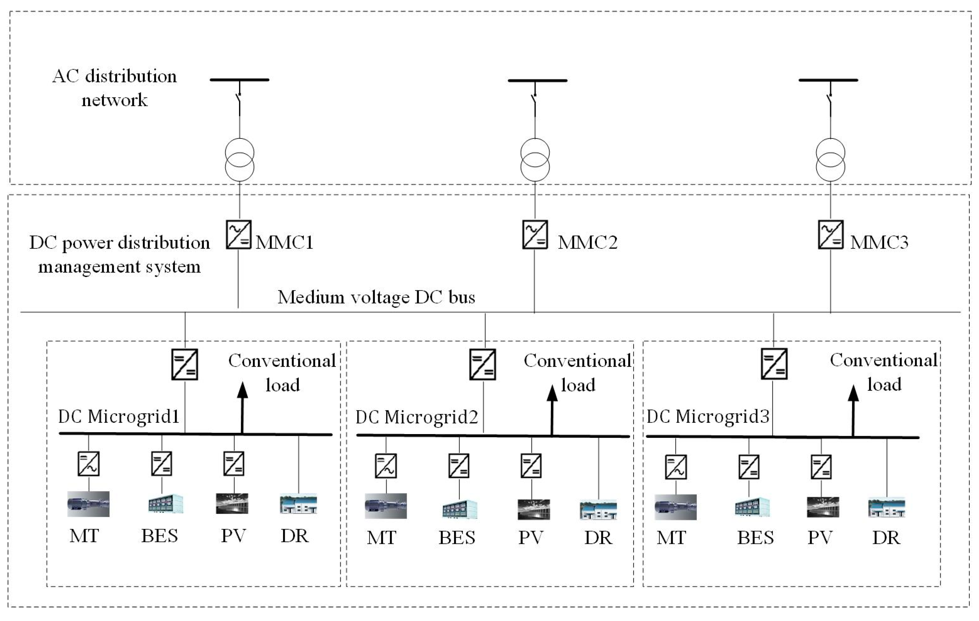
Figure 2.
IEEE33 power distribution system.
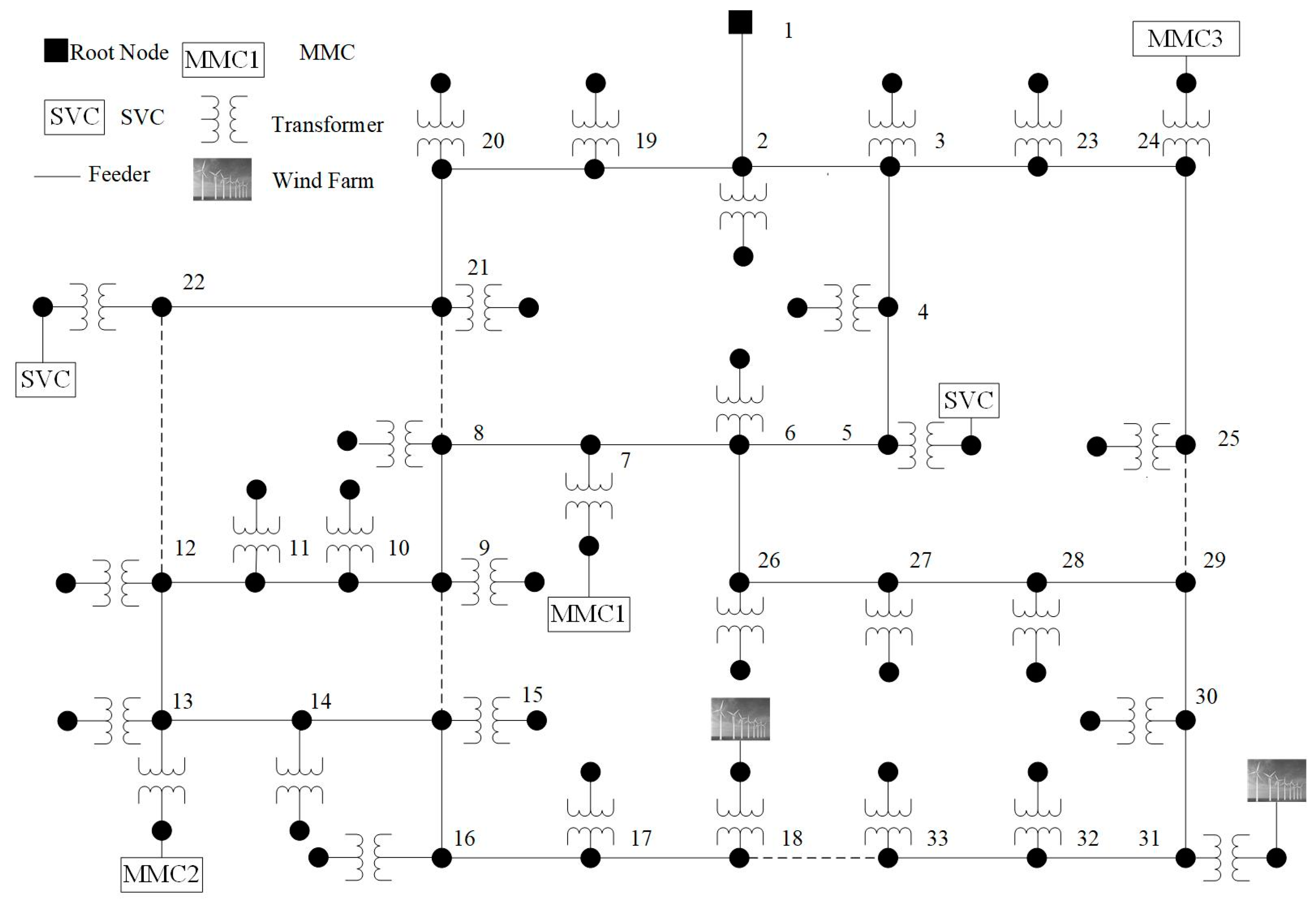
Figure 3.
Load, illumination, and wind speed curve (per-unit value).
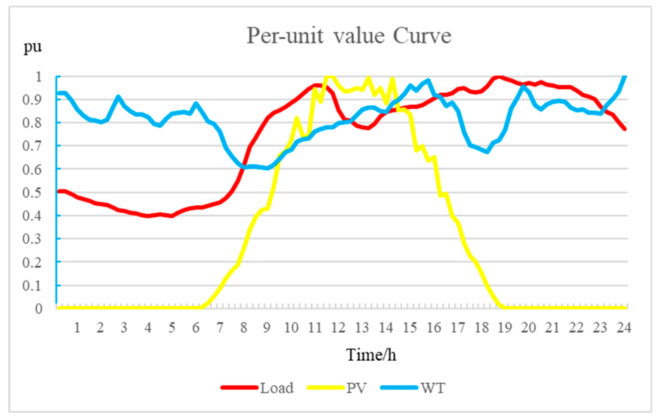
Figure 4.
Optimization results of DC microgrid 1.

Figure 5.
Active output for centralized wind farms.
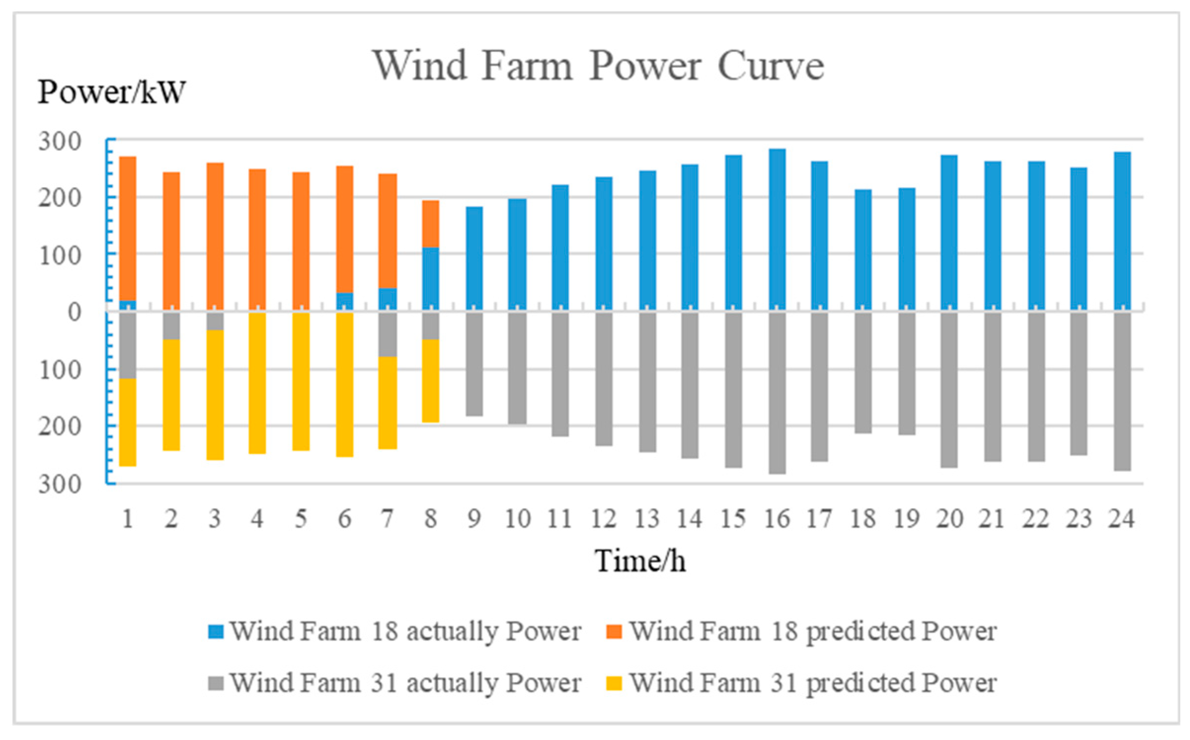
Figure 6.
Active power of AC side of modular multilevel converters (MMCs).
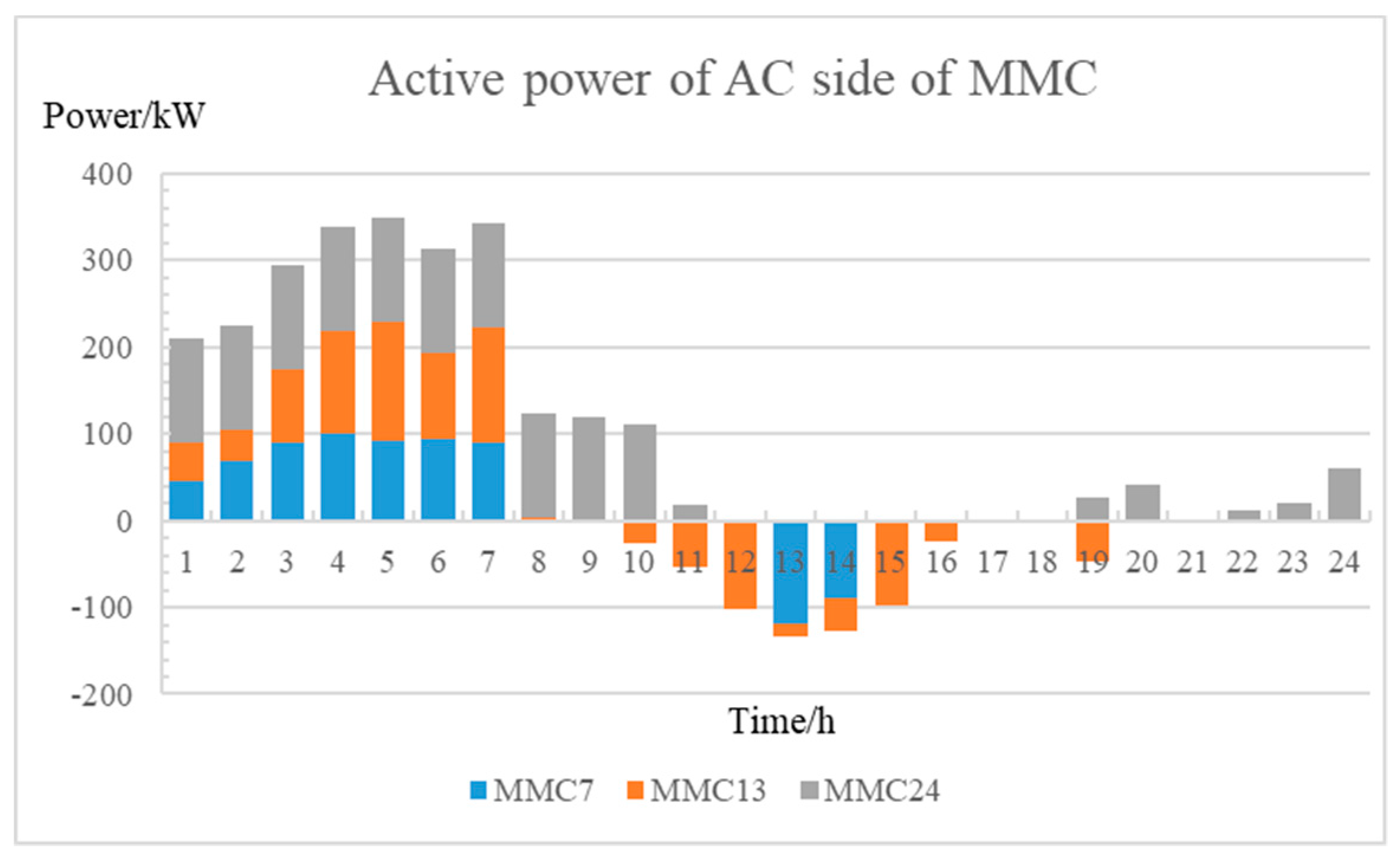
Figure 7.
Transmission losses of the power distribution network.
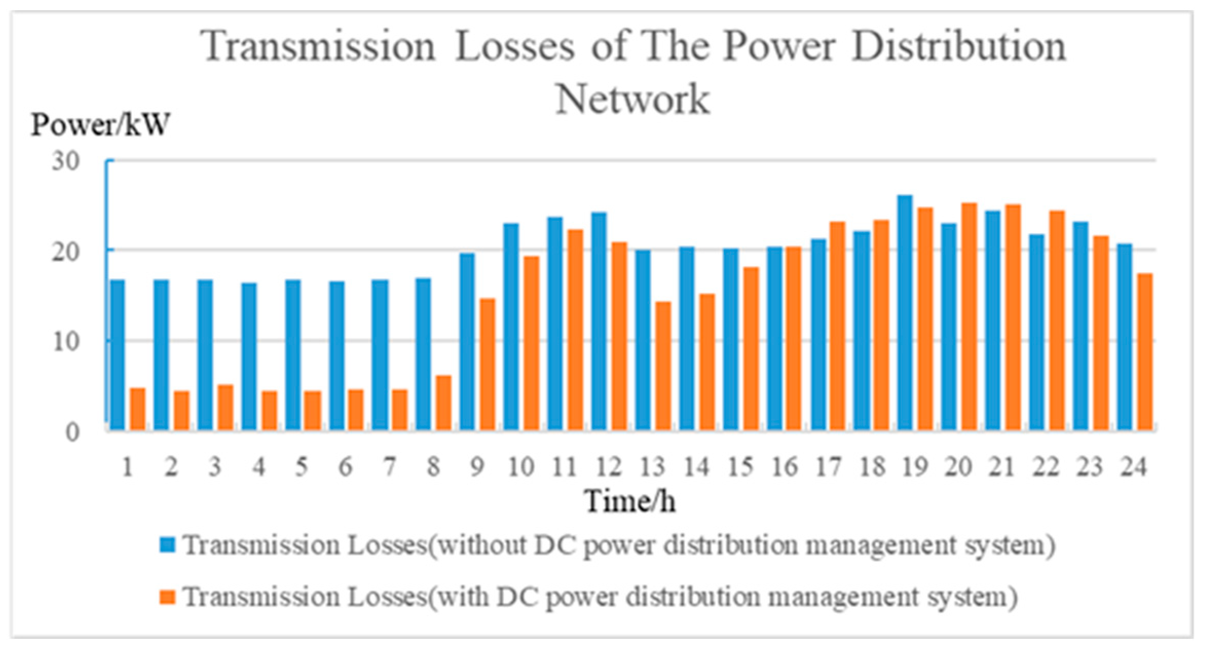
Figure 8.
Active power for the root node.
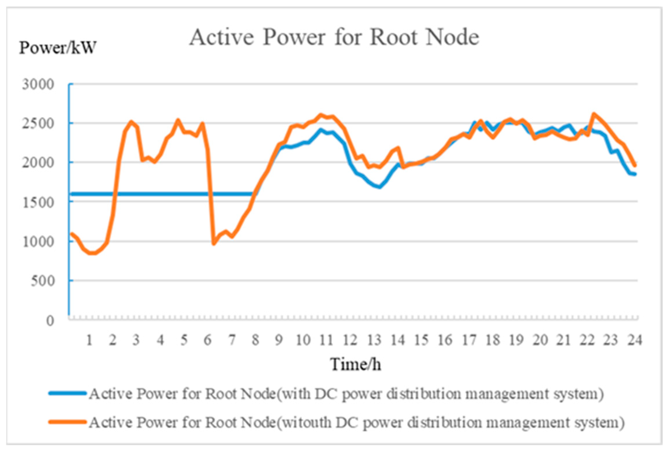
Figure 9.
Circumstances for wind power utilization.


Table 1.
Microgrid parameters. DC: direct current, PV: photovoltaic, BES: battery-type energy storage, MT: microturbine.
Table 1.
Microgrid parameters. DC: direct current, PV: photovoltaic, BES: battery-type energy storage, MT: microturbine.
| DC Microgrid | Microgrids Capacity/KW | PV Power/KW | BES Power/KW | BES Capacity/KW | MT Power/kw | Demand-Side Response Power/KW |
|---|---|---|---|---|---|---|
| MG1 | 100 | 100 | 80 | 400 | 30 | 15 |
| MG2 | 120 | 80 | 60 | 300 | 20 | 15 |
| MG3 | 80 | 120 | 120 | 600 | 40 | 20 |
© 2019 by the authors. Licensee MDPI, Basel, Switzerland. This article is an open access article distributed under the terms and conditions of the Creative Commons Attribution (CC BY) license (http://creativecommons.org/licenses/by/4.0/).
Share and Cite
MDPI and ACS Style
Peng, Q.; Yuan, Z.; Ouyang, B.; Guo, P.; Qu, L. Research on the Optimal Operation Method of DC Microgrid Base on the New DC Power Distribution Management System. Electronics 2020, 9, 9. https://doi.org/10.3390/electronics9010009
AMA Style
Peng Q, Yuan Z, Ouyang B, Guo P, Qu L. Research on the Optimal Operation Method of DC Microgrid Base on the New DC Power Distribution Management System. Electronics. 2020; 9(1):9. https://doi.org/10.3390/electronics9010009
Chicago/Turabian StylePeng, Qingwen, Zhichang Yuan, Bin Ouyang, Peiqian Guo, and Lu Qu. 2020. "Research on the Optimal Operation Method of DC Microgrid Base on the New DC Power Distribution Management System" Electronics 9, no. 1: 9. https://doi.org/10.3390/electronics9010009
Note that from the first issue of 2016, this journal uses article numbers instead of page numbers. See further details here.