1. Introduction
A solid-state terahertz mixer is one of the key components of the terahertz system, which has been widely used in the fields of remote sensing, communication, and radar. At present, the operating frequency of radiometers has reached terahertz frequency and has broad application prospects in the fields of meteorological forecasting, global water cycle observation, and marine environmental monitoring [
1,
2,
3]. There are many satellites that carried the terahertz load and are running in orbit. The highest operating frequency of the radiometer researched by the JPL (Jet Pulse Laboratory) has reached 2 THz [
4].
183 GHz is an important frequency window of atmosphere water vapor absorption, which has been widely used in remote sensing and atmosphere limb detection [
5,
6,
7]. In microwave humidity sounders, the 183 GHz channel is used to judge the convection type of the water vapor, such as the “Feng-Yun” series polar orbiting meteorological satellites in China [
8,
9]. In atmosphere limb sounders, the 183 GHz channel is used to measure the distribution and content of water vapor and ozone in the stratosphere and intermediate layers, such as EOS-MLS [
6] and UARS-MLS [
7] in the United States.
The solid-state terahertz receiving system can work at room temperature and does not require refrigeration equipment, which can effectively reduce the volume and weight of the satellite load. The heterodyne architecture is widely used in the terahertz radiometer receivers, and the sub-harmonic mixing method is commonly utilized [
10,
11,
12,
13]. Currently, mature commercial low noise amplifiers in the market are unable to obtain excellent noise performance above 150 GHz. The sub-harmonic mixer acts as the first stage of the receiver, and its performance directly determines the performance of the receiver system.
Based on the anti-parallel Schottky diode developed by Teratech, a novel 183 GHz solid-state sub-harmonic mixer is designed and measured in this paper. To reduce the effects of random assembly error of the conductive adhesive at the DC ground on the mixer’s performance and stability, this design adds a grounding LPF (low-pass filter) near the DC ground.
In order to verify the effectiveness of the proposed mixing architecture, simulation, measurement, and comparison are performed based on a mixer working at the same frequency with no grounding LPF. First, the variation of conversion loss, RF return loss, and LO return loss on the two mixers are simulated and compared when using five different shapes conductive adhesive. Second, two same mixers are assembled of each topology, and the variation on conversion loss and RF return loss is tested and analyzed.
2. Mixer Design
2.1. Circuit Topology
The mixing principle of the anti-parallel Schottky diode pair is analyzed in [
14] by Cohn M. The frequency components of the mixing current of the anti-parallel Schottky diode can be expressed as
, where m + n is an odd number. Mixers using anti-parallel diode can suppress odd harmonic components, and thus have higher mixing efficiency and dynamic range than a single diode. For the 183 GHz sub-harmonic mixer designed, the required IF (intermediate-frequency) signal frequency is
.
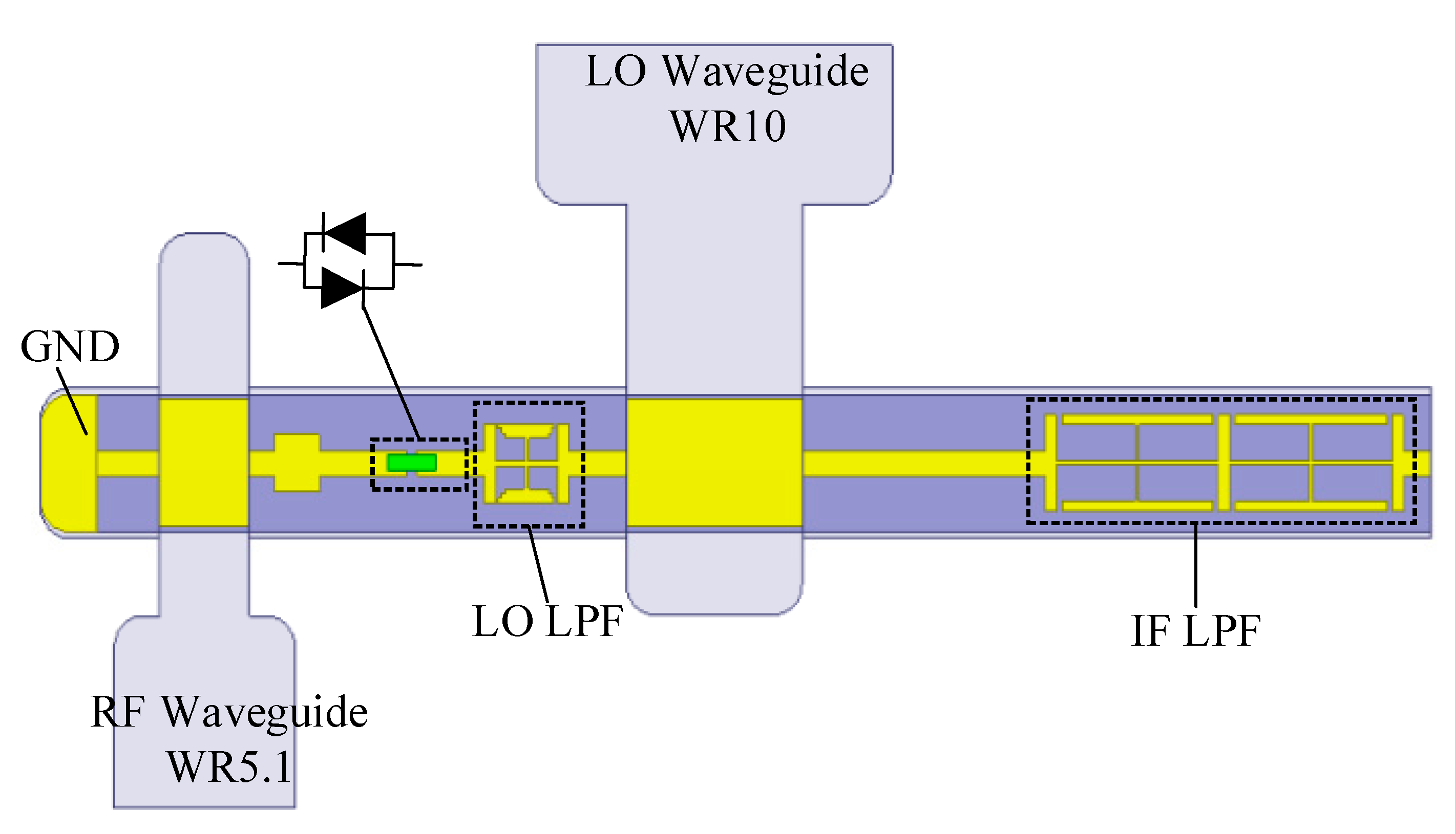
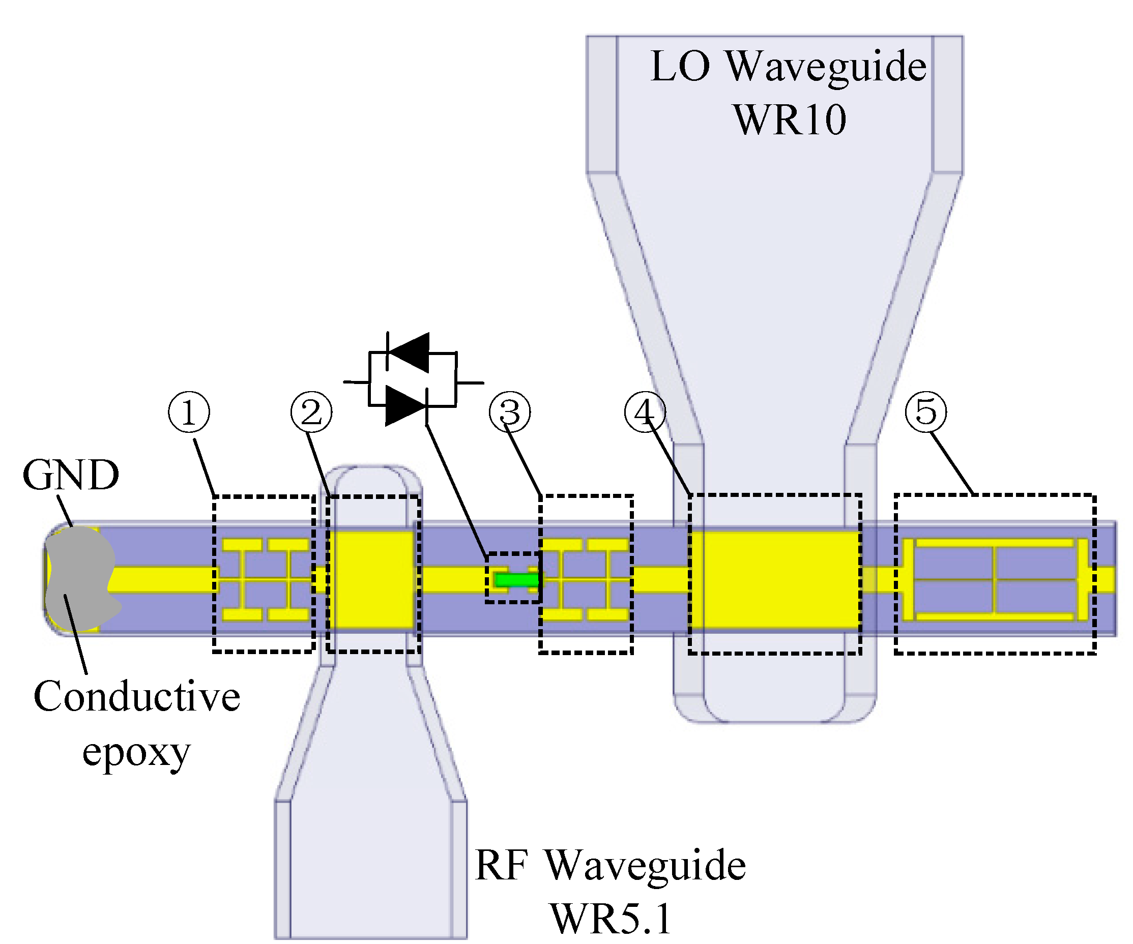
Figure 1 shows the proposed circuit structure of the sub-harmonic mixer in this paper. The RF signal and the LO (local oscillator) signal are feed by standard rectangular waveguides of WR5.1 and WR10, respectively, and the working mode is TE10. As can be seen from the figure, the mixer circuit is integrated on a quartz substrate with a thickness of 50 µm, including grounding LPF ①, RF coupling probe ②, LO LPF ③, LO coupling probe ④, IF LPF ⑤, and anti-parallel Schottky diode. The anti-parallel Schottky diode is flipped mounted on the quartz substrate, and the substrate is soldered with the mixer cavity by the conductive adhesive.
In the traditional terahertz sub-harmonic mixer structure, the RF probe is directly coated with conductive adhesive through a transmission line to realize DC ground. The DC grounding is one part of the matching circuit in the design. The phase of the grounding part changes randomly if the conductive adhesive is random. Besides, the conductivity of conductive adhesive is not ideal and cannot be accurately characterized in simulation, as the conductive adhesive is the self-made mixture of epoxy and silver. Moreover, the random smear of the conductive adhesive on the transmission line changes the impedance and electrical length characteristics of the line. The error mentioned above directly leads to circuit mismatch and deteriorates the performance on conversion loss, bandwidth, and return loss.
In order to solve the problem mentioned above, a grounding low-pass filter is added near the DC ground, as shown in
Figure 1 of ①. The grounding LPF acts open to the RF signal and suppresses the coupling of the RF signal to the ground. This can effectively reduce the influence of the random assembly error of the conductive adhesive at the grounding on the conversion loss. At the same time, the low pass filter provides short for the LO signal.
2.2. Anti-Parallel Diode Model
The Schottky diode is the majority carrier device that has fast electronic response and is suitable for high-frequency applications [
15]. The anti-parallel Schottky diode is the core component of the mixer circuit, and its performance directly determines the conversion loss characteristics and noise characteristics of the mixer. The characteristic of a Schottky junction is usually characterized by DC parameters such as zero-bias junction capacitance (
), series resistance (
), saturation current (
), ideal factor n, and barrier height (
). Small
produces lower conversion loss and lower noise, while small
leads to smaller shunts for the nonlinear resistance. An AP1-G2-0p64 anti-parallel Schottky diode pair of Teratech with high performance is utilized for the proposed mixer. The DC parameters are shown in the following
Table 1.
The cut-off frequency of a Schottky diode can be calculated by the following Equation (1). Combined with Equation (1) and the parameters shown in
Table 1, the cut-off frequency of the diode used in this design is 9.34 THz, which fully meets the design requirement.
Since the mixer designed works in the terahertz band, the physical size of the diode is comparable to the signal wavelength. Therefore, the physical structures of the diode package (pad, metal finger, etc.) have large effect on the electric field distribution of the signal. The traditional equivalent circuit model cannot meet circuit design in the terahertz band, so it is necessary to establish an accurate 3-D (three-dimensional) electromagnetic model based on the actual physical structure and material parameters of the diode.
The 3-D electromagnetic model of the Schottky diode is built in the full-wave HFSS (high-frequency structure simulation) software. As shown in
Figure 2, the Schottky diode is composed of anode/cathode pads, anode metal fingers, the oxide layer, the epitaxial layer, the buffer layer, and GaAs (gallium arsenide) semiconductor substrate. The anode metal and the epitaxial layer form a Schottky junction. The ohmic contact is formed by the contact of the cathode pad and the buffer layer. In HFSS, the lightly doped epitaxial layer is set as gallium arsenide material, and the heavily doped buffer layer is set as PEC (perfect electric conductor). The ring coaxial wave port is set to characterize the Schottky junction.
2.3. Low-Pass Filter Design
From the above analysis of the mixer’s structure, the grounding LPF, the LO LPF, and the IF LPF are the core components of the mixer proposed. The high-low-impedance LPF is widely used, which has the advantages of simple structure and simple design method, while the disadvantage of longer size that causes large transmission loss and dispersion. The LPF of CMRC (compact microstrip resonant cell) structure has a small physical size, high out-of-band rejection, and small dispersion characteristics [
16].
The grounding LPF and the LO LPF are designed as the same filter since they have the same function of preventing leakage of the RF signal. The LPF is designed by using a two-stage “I-shape” CMRC structure, which introduced more capacitors and inductors compared with the traditional high-low impedance filter.
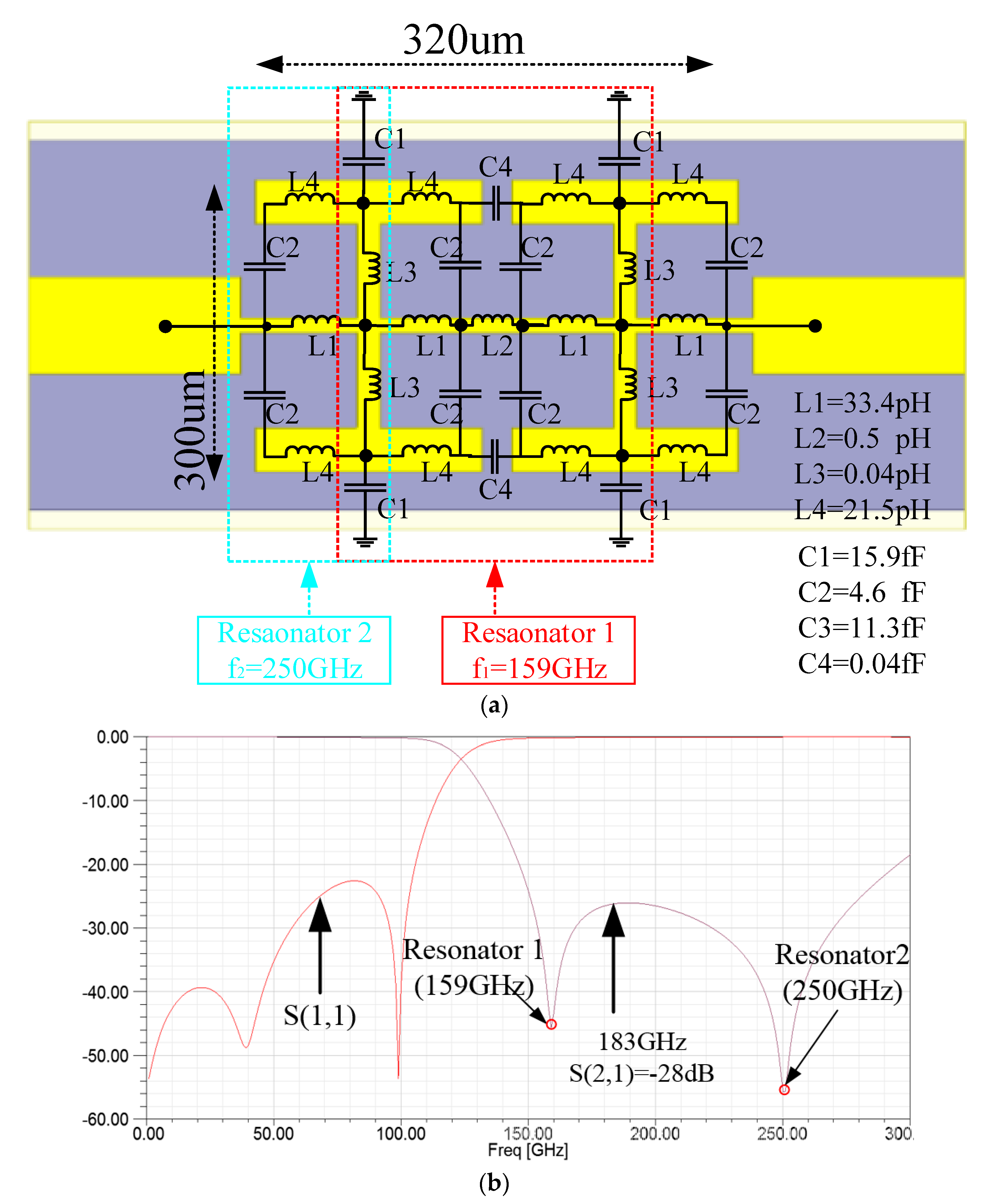
Figure 3a shows the structure and equivalent circuit of the LPF, where capacitors and inductors are introduced by stripeline branches, gaps, and edge effects. As shown in
Figure 3b, there are two resonant poles in the rejection band, which is located at 159 GHz (resonator 1) and 250 GHz (resonator 2). Resonator 1 locates in the main rejection band of the LPF. Gap coupling between the two “I-shape” brings two coupling capacitors (C4), which establish resonator 1 with inductors (L1, L2, L3, L4) that are produced by high impedance lines shown. The capacitors produced by coupling of branches (C2) and edge effect (C1) resonate with inductance (L1, L4) to form the resonator 2 shown in
Figure 3a, which eliminates the first parasitic rejection band and broaden the rejection band. Because of the two resonate poles, the S(2,1) of the LPF is less than −25 dB in the band of 150 GHz to 280 GHz, which can effectively suppress the leakage and coupling of RF signal. At the same time, the insertion loss is lower than 0.3 dB in the band of 0 GHz~110 GHz.
The function of the IF LPF is to suppress the leakage of the LO signal to the output port, which improves the utilization of the LO signal. The structure, equivalent circuit, and the simulated result of the IF LPF are depicted in
Figure 4. As shown in
Figure 4b, there is only one resonant pole at 83 GHz because of the one-stage CMRC structure. The S(2,1) simulated is less than −20 dB in the 75 GHz~120 GHz band, which can effectively suppress the leakage of the LO signal to the IF output port.
3. Simulation
The overall simulation and optimization process of the 183 GHz sub-harmonic mixer is divided into four steps. Step 1, the S parameters of each discrete passive structure are obtained by the electromagnetic simulation software HFSS. Step 2, the mixer circuit is built in the circuit simulation software ADS, and the harmonic balance algorithm is used to optimize the mixer matching circuit. Step 3, the complete passive mixer circuit is modeled in HFSS, and then combines the harmonic balance algorithm with and the S parameters extracted from HFSS to simulate the overall mixer’s performance. Step 4, the final mixer circuit is obtained by iterative optimization.
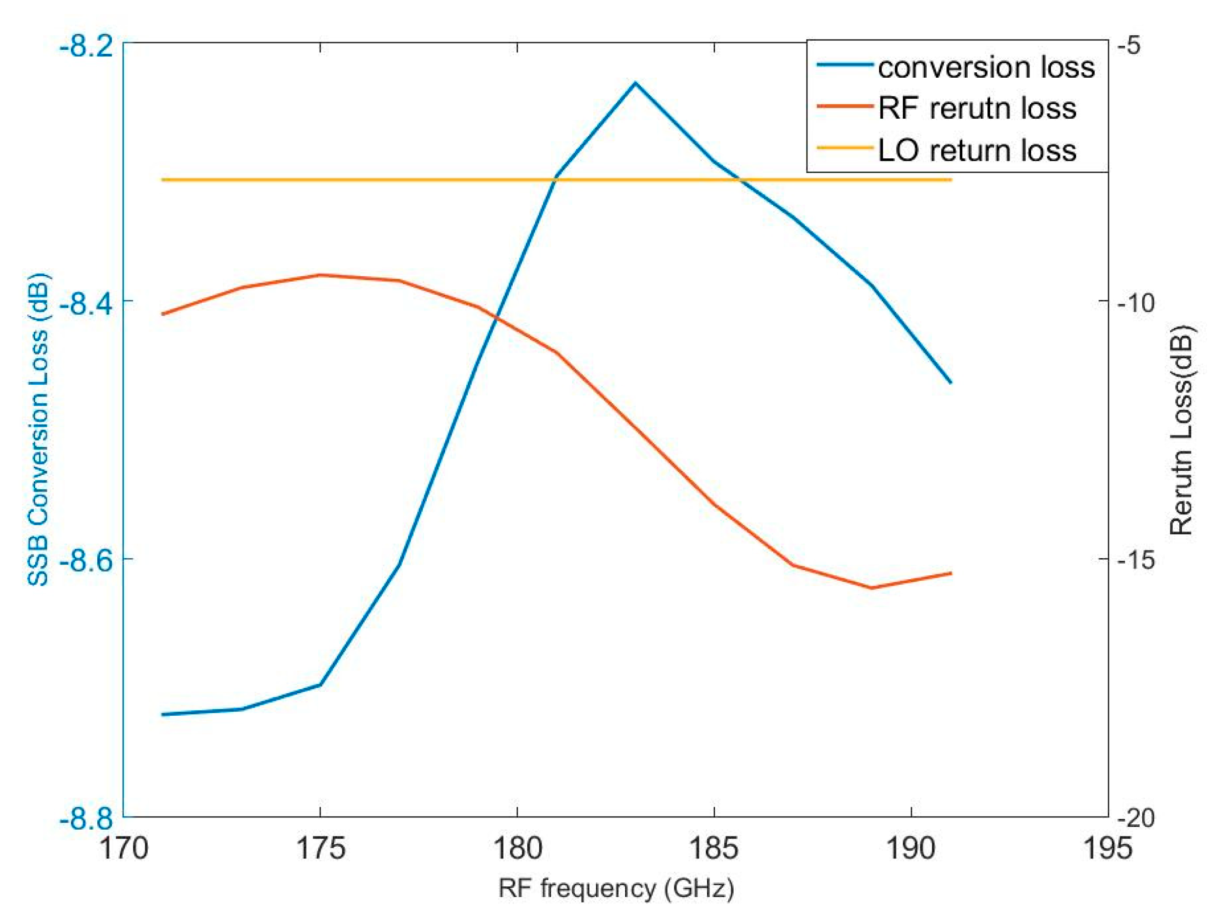
Figure 5 shows the simulation results of the proposed 183 GHz sub-harmonic mixer. When the LO signal is fixed at 4mw@91GHz, the optimal SSB (single-sideband) conversion loss of the mixer is 8.25dB@182GHz, and the SSB conversion loss is better than 8.7 dB among 170 GHz~190 GHz. It can be seen that the return loss of the RF port is less than −9 dB in the band of 170 GH~190 GHz. Because the LO frequency is fixed at 91 GHz, the return loss of the LO port is fixed at −7.7 dB.
To verify the novel topology proposed in this paper, we used the mixer designed before as comparison which is working at the same frequency. There is no grounding LPF in the topology, as shown in
Figure 6. The conversion loss, RF and LO return loss is shown in
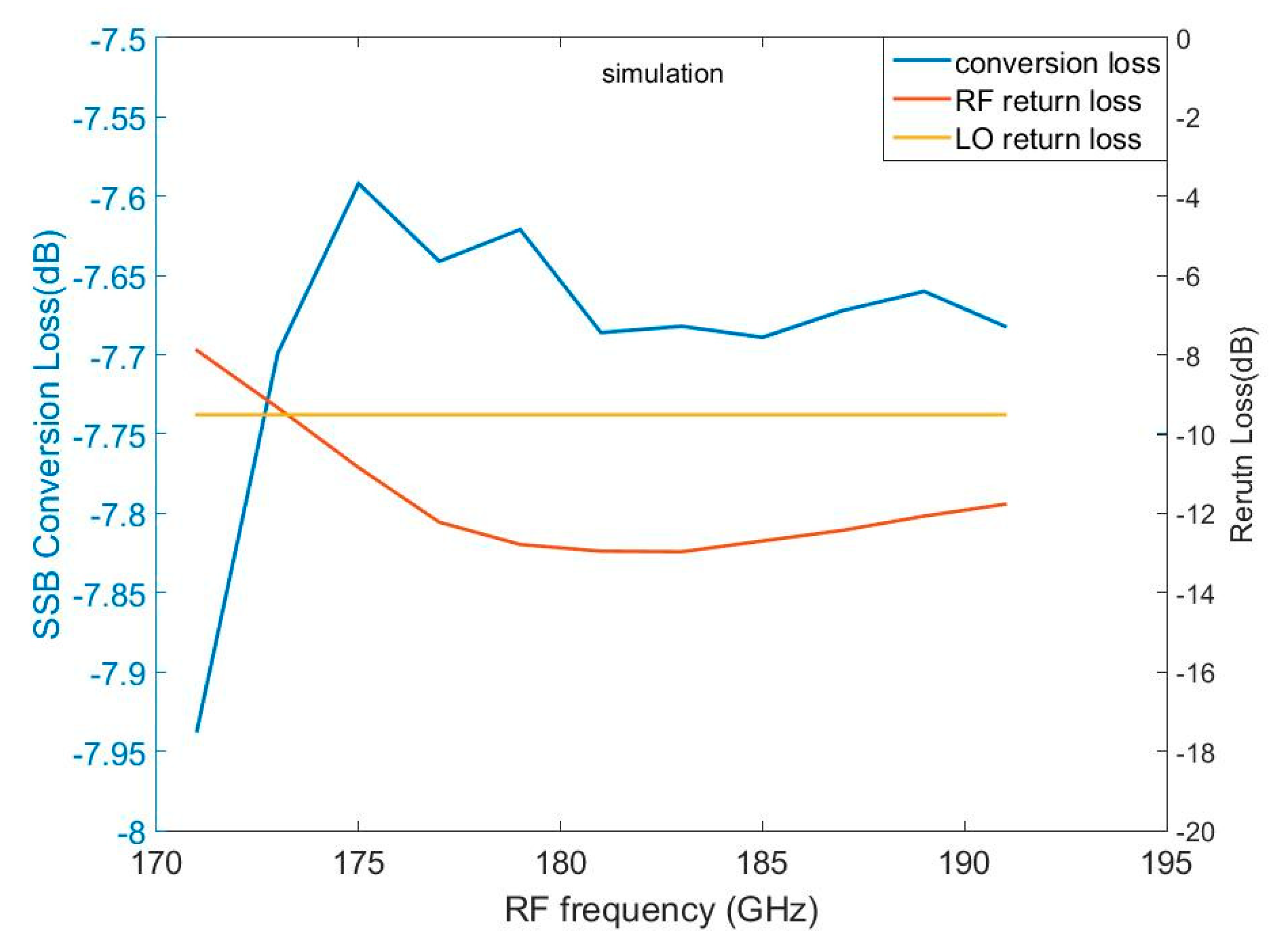
Figure 7. The conversion loss is better than 8 dB at the 170 GHz~190 GHz, which has a minimum of 7.6 dB at 175 GHz. At the band of 170 GHz~190 GHz, the RF return loss is better than −8 dB, while the LO return loss is the fixed value of −9.5 dB.
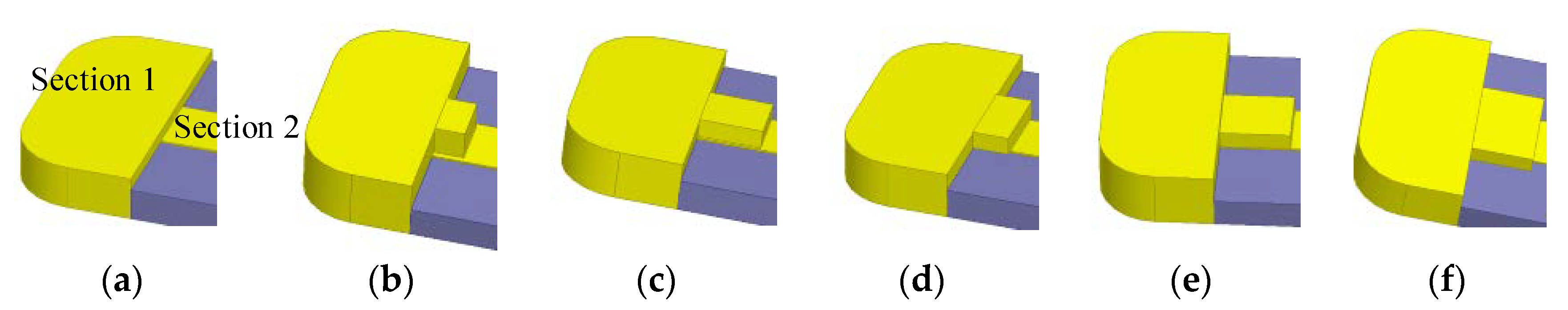
As shown in
Figure 8, the conductive adhesive can be divided into two sections.
Section 1 is filled of adhesive, while
Section 2 is random on the transmission line which affects the mixer’s performance. In the simulation process, five cuboids are defined to represent
Section 2, which has reasonable random length, width, and height. The size of the five cuboids are (50,80,50), (100,90,30), (60,120,50), (120,100,30), (110,150,30).
We defined mixer 1 that used topology shown in
Figure 1, while mixer 2 that in
Figure 6. The variation of conversion loss, RF return loss, and LO return loss compared with ideal assembling of mixer 1 and mixer 2 is illustrated in
Figure 9 and
Figure 10, respectively.
Table 2 shows the variation range of the comparison presented in
Figure 9 and
Figure 10.
As listed in
Table 2, when the conductive adhesive is randomly changed, the variation of conversion loss, RF return loss, and LO return loss of mixer 1 are lower than 0.017 dB, 0.02 dB, and 0.05 dB, respectively. However, the variation of mixer 2 is obviously higher than mixer 1, which can verify the grounding LPF can decrease the affection of random conductive adhesive.
4. Measurement and Discussion
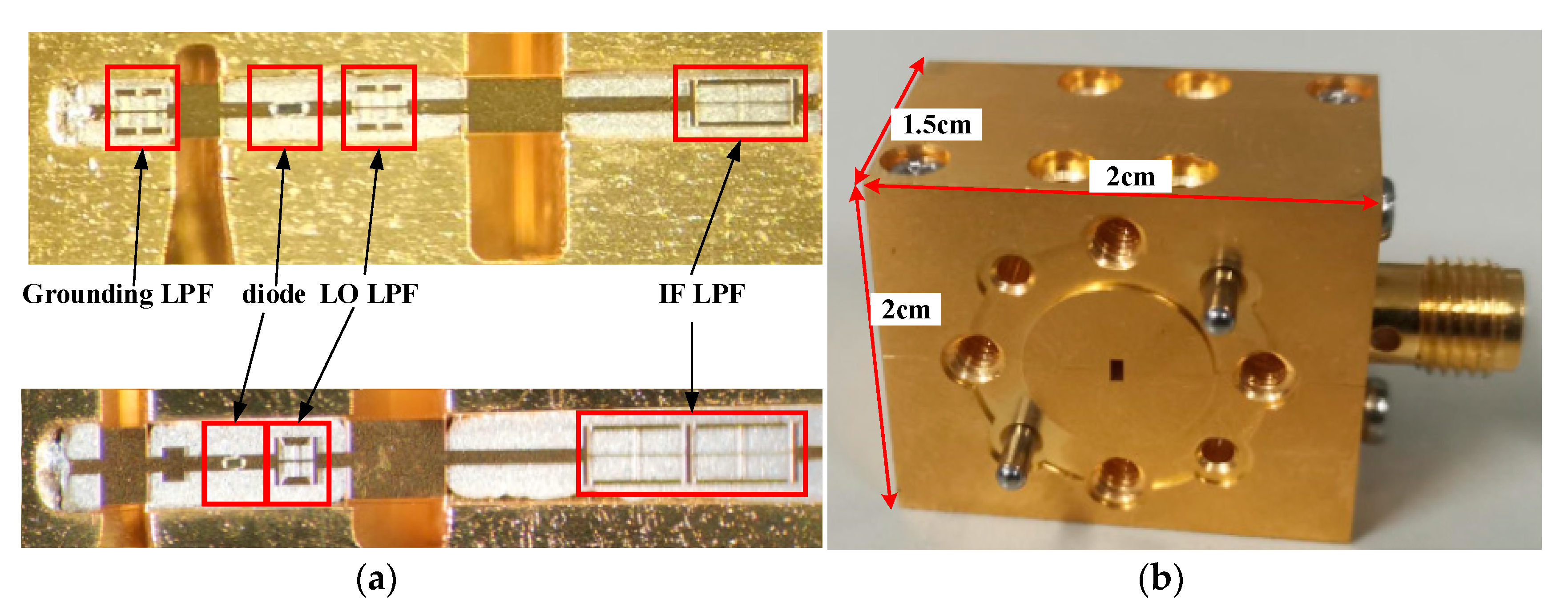
The photography of mixer 1 and mixer 2 are shown in
Figure 11. The mixer’s circuit is integrated on a 50 µm thick quartz substrate and packaged in the mixer’s block which is split from the E-plane and fixed by screws. The block also integrates standard flanges and an SMA connector for the RF signal, LO signals, and IF signal, respectively. The size of the mixer’s block is 2 cm × 2 cm × 1.5 cm.
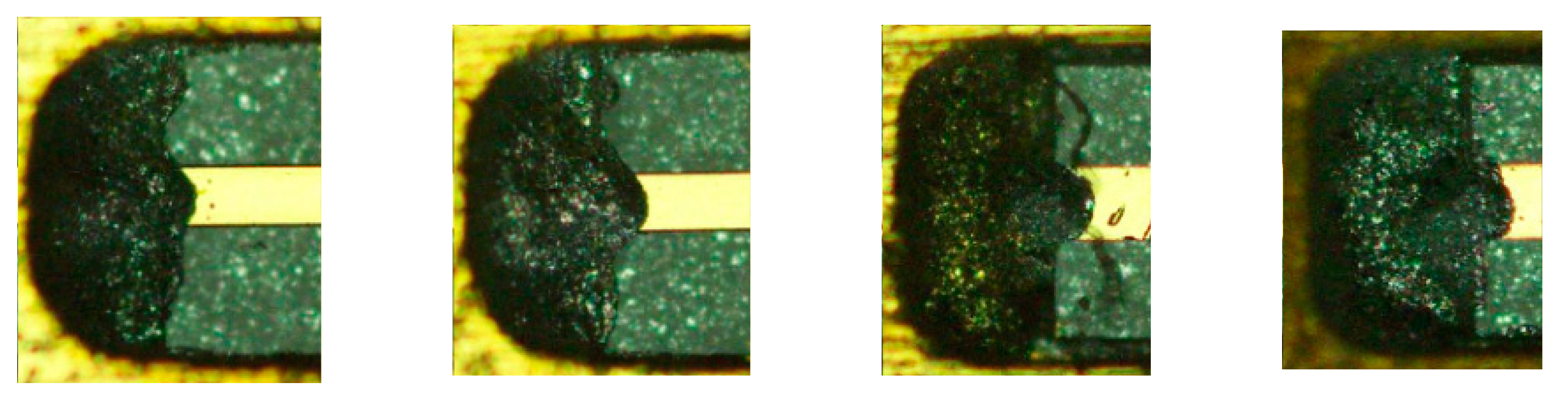
Two blocks are fabricated and assembled for each topology, called mixer 1_1, mixer 1_2, mixer 2_1, and mixer 2_2. As shown in
Figure 12, the shape of conductive adhesive in the DC ground of four different mixers is different and random.
The performance of the 183 GHz sub-harmonic mixer is measured by using the down-conversion method. The test block diagram and test bench are shown in
Figure 13. The required RF signal (small signal) is generated by Farran’s VNA (vector network analyzer) expansion module which has a multiplication number of 12. The output RF power is maintained at about −15 dBm at the band of 170 to 200 GHz. The standing wave of RF port can be tested at the same time by the VNA (Agilent N5247a). The LO signal is generated by a frequency multiply and amplify link shown in
Figure 13. The LO chain is composed of the Agilent 8267D signal source (X-band signal) and *8 frequency multiplier chain (90 GHz–100 GHz). The LO signal produced is greater than 5 mw. The IF signal generated by the mixer is output to the spectrum analyzer (Agilent 9030A) through the SMA connector and coaxial cable, and the power of IF signal and the SSB conversion loss are analyzed and calculated.
To decide the optimal LO power, the optimal conversion loss at the 183 GHz frequency point under different LO power is tested when the LO signal frequency is fixed at 91 GHz. Finally, the LO power is determined to be 4 mw.
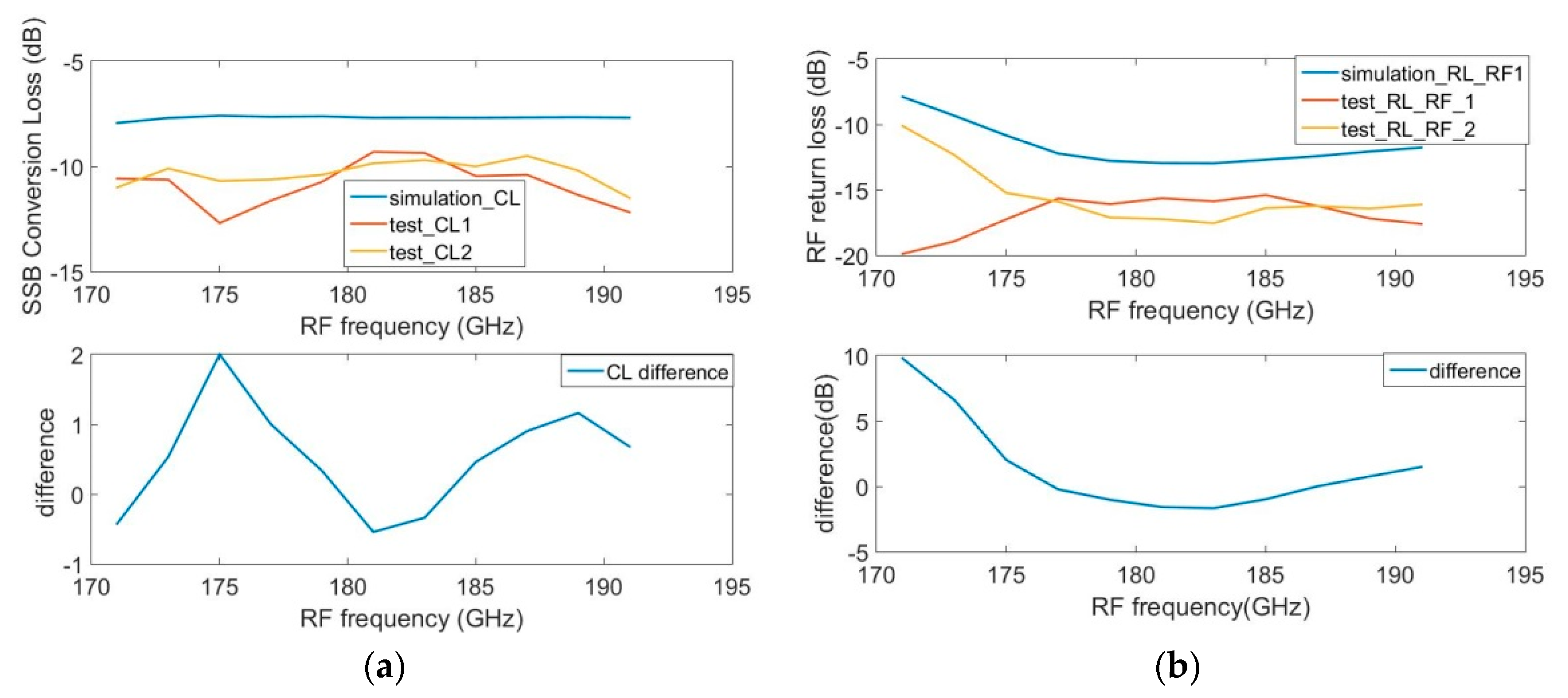
Figure 14 shows the measurement performance of mixer 1_1 and 1_2. The test results show that the optimal SSB conversion loss of mixer 1_1 and mixer 1_2 is about 8.1dB@183GHz when the LO power is fixed at 4mw@91GHz. It also can be seen that the SSB conversion loss is better than 10.6 dB in the RF band of 173 GHz~191 GHz. However, when the RF signal is extended to both sides of the center frequency, the deviation of conversion loss between the test and the simulation increases gradually, and the deviation reaches 3 dB at 171 GHz.
Figure 14b shows the return loss curve at RF port under test and simulation. The test results show that the RF port return loss is less than −9.8 dB over the entire test band and the test curve has the same trend with the simulation.
Mixer 1_1 and mixer 1_2 have the same tendency in conversion loss and RF return loss measurement curves. And the maximum difference of the conversion loss and RF return loss is 0.2 dB and 3 dB, respectively. One reason can explain the phenomenon above. The parameters of the Schottky diode junction utilized are deviated from actual values because the Schottky junction generates parasitic capacitance and resistance at high frequencies.
Figure 15 represents the test results of mixer 2_1 and 2_2. From
Figure 15a, the tendency of conversion loss of mixer 2_1 and 2_2 are approximately the same, and the maximum difference is 2 dB at 175 GHz. However, the trends of RF return loss of mixer 2_1 and 2_2 have no similarity, where the difference reaches 9.8 dB at 171 GHz.
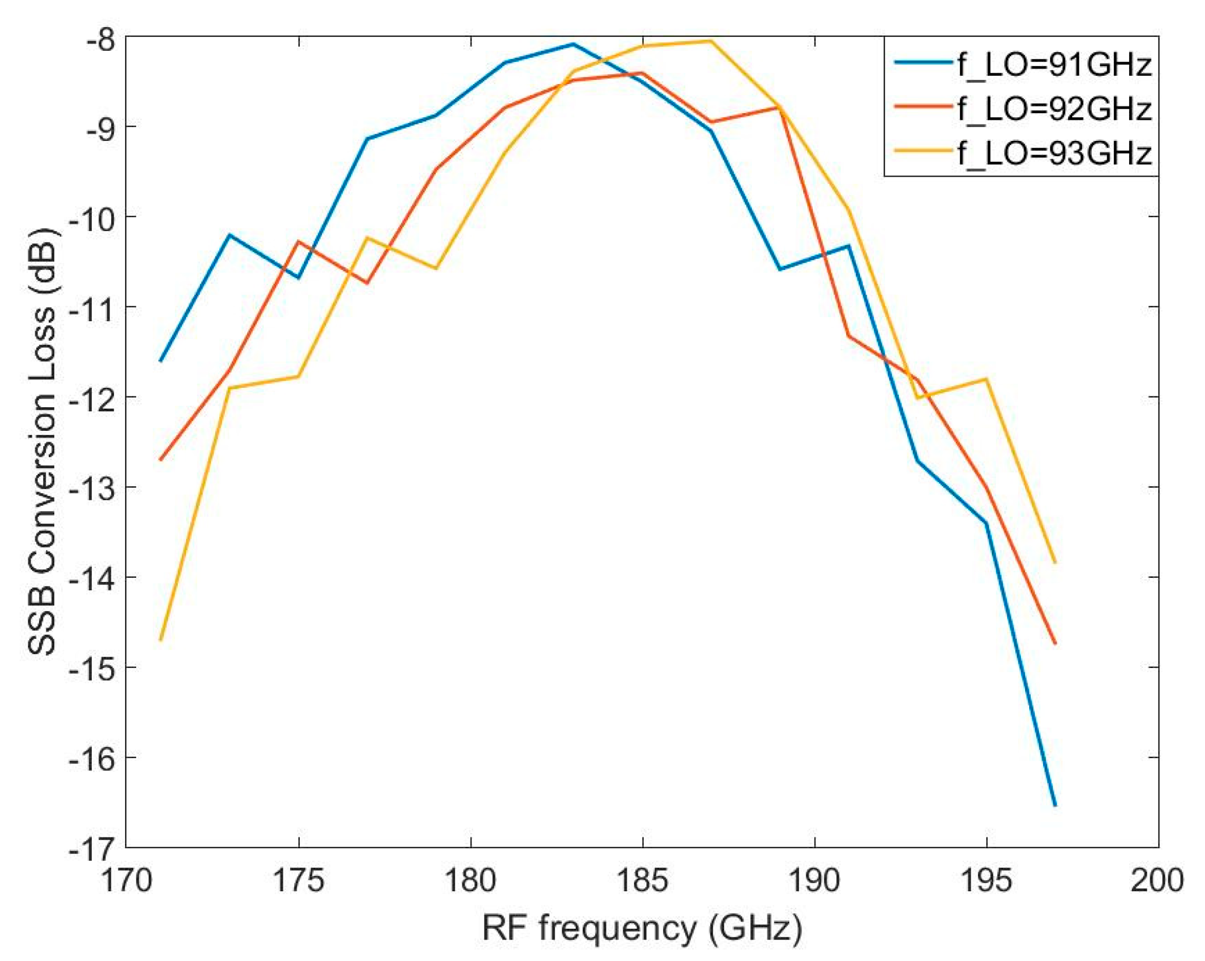
The SSB conversion loss under different LO frequency is tested and shown in
Figure 16. The optimal SSB conversion loss is 8.1dB@183GHz, 8.4dB@185GHz, and 8.1dB@187dB when the LO frequency is 91 GHz, 92 GHz, and 93 GHz, respectively. Since the optimal conversion loss is generally achieved at low IF frequency, the curve in
Figure 16 shifts to a higher frequency when the LO frequency is high, which is similar to simulation. The 3 dB flatness bandwidth is about 20 GHz at the above LO frequency, which explains the robust performance of the mixer.
Table 3 lists the comparison of different sub-harmonic mixers working at 183 GHz with the mixer in this paper. As can be seen from
Table 3, the proposed sub-harmonic mixer designed is close to the international advanced level in terms of performance.
5. Conclusions
In this paper, a novel sub-harmonic mixing topology is proposed which can effectively reduce the effect of random assembly error on the mixer’s RF performance by adding a low-pass filter near the DC ground. A solid-state sub-harmonic mixer with low-conversion loss operating at 183 GHz is designed and tested based on the proposed circuit topology and anti-parallel Schottky barrier diode. The effectiveness of the proposed topology is verified based on the comparison and analysis of the simulation, measurement with a mixer with no grounding LPF at 183 GHz. The test results show that the minimum SSB conversion loss of the mixer is 8.1dB@183GHz. The SSB conversion loss is less than 10.6 dB in the RF bandwidth of 173 GHz~191 GHz. In the 170 GHz~195 GHz, the return loss of the mixer’s RF port is better than −9.8 dB. This work lays a foundation for terahertz space applications in China.
Author Contributions
Conceptualization, methodology, software, and writing, G.J., D.Z., and J.M.; investigation, C.Y.; visualization, G.J. and S.L. All authors have read and agreed to the published version of the manuscript.
Funding
This research received no external funding.
Conflicts of Interest
The authors declare no conflict of interest.
References
- Kangaslahti, P.; Schlecht, E.; Jiang, J.; Deal, W.R.; Jiang, J.; Deal, W.R.; Zamora, A.; Leong, K.; Reising, S.C.; Bosch, X.; et al. CubeSat scale receivers for measurement of ice in clouds. In Proceedings of the 14th Specialist Meeting on Microwave Radiometry and Remote Sensing of the Environment, Espoo, Finland, 11–14 April 2016. [Google Scholar]
- Thomas, B.; Gill, J.; Maestrini, A.; Lee, C.; Lin, R.; Sin, S.; Peralta, A.; Mehdi, I. An integrated 520–600 GHz sub-harmonic mixer and tripler combination based on GaAs MMIC membrane planar Schottky diodes. In Proceedings of the 35th International Conference on Infrared Millimeter & Terahertz Waves, Rome, Italy, 5–10 September 2010. [Google Scholar]
- Thomas, B.; Maestrini, A.; Matheson, D.; Maagt, O.D. Design of an 874 GHz biasable sub-harmonic mixer based on MMIC membrane planar schottky diodes. In Proceedings of the 33rd International Conference on Infrared, Millimeter and Terahertz Waves, Pasadena, CA, USA, 15–19 September 2008. [Google Scholar]
- Treuttel, J.; Schlecht, E.; Siles, J.; Lee, C.; Lin, R.; Thomas, B.; Gonzalez-Olvero, D.; Yee, J.H.; Wu, D.I.; Mehdi, I. A 2 THz Schottky solid-state heterodyne receiver for atmosphere studies. In Proceedings of the SPIE Astronomical Telescopes + Instrumentation. Millimeter, Submillimeter, and Far-Infrared Detectors and Instrumentation for Astronomy VIII, Edinburgh, UK, 16 June 2016; Available online: https://www.nrao.edu/meetings/isstt/2012.shtml (accessed on 17 January 2020).
- Viegas, C.; Alderman, B.; Powell, J.; Liu, H.; Wang, H.; Sloan, R. Millimeter wave radiometers for applications in imaging and nondestructive testing. In Proceedings of the 8th UK, Europe, China Millimeter Waves and THz Technology Workshop, Cardiff, UK, 14–15 September 2016. [Google Scholar]
- Waters, J.W.; Froidevaux, L.; Harwood, R.S.; Jarnot, R.F.; Pickett, H.M.; Read, W.G.; Siegel, P.H.; Cofield, R.E.; Filipiak, M.J.; Flower, D.A.; et al. The Earth Observing System Microwave Limb Sounder (EOS MLS) on the Aura Satellite. IEEE Trans. Geosci. Remote Sens. 2006, 44, 1075–1092. [Google Scholar]
- Reber, C.A.; Trevathan, C.E.; Mcneal, R.J.; Luther, M.R. The Upper Atmosphere Research Satellite (UARS) mission. J. Geophys. Res. Atmos. 1993, 98, 10643–10647. [Google Scholar] [CrossRef]
- Yang, J.; Dong, C.H.; Lu, N.M.; Yang, Z.H.; Shi, J.M.; Zhang, P.; Liu, Y.J.; Cai, B. FY-3A: The New Generation Polar-Orbiting Meteorological Satellite of China. Acta Meteorol. Sin. 2009, 67, 501–509. [Google Scholar]
- Zhang, S.W.; Li, J.; Wang, Z.Z.; Wang, H.J.; Sun, M.H.; Jiang, J.S.; He, J.Y. Design of the second generation microwave humidity sounder (MWHS-II) for Chinese meteorological satellite FY-3. In Proceedings of the IEEE International Geoscience and Remote Sensing Symposium, Munich, Germany, 22–27 July 2012. [Google Scholar]
- Yao, C.F.; Chen, Z.H.; Ge, J.X.; Zhou, M.; Wei, X. A Compact 220 GHz Heterodyne Receiver Module with Planar Schottky Diodes. AEU-Int. J. Electron. Commun. 2017, 84, 153–161. [Google Scholar] [CrossRef]
- Schlecht, E.T.; Gill, J.J.; Lin, R.H.; Dengler, R.J.; Medhei, I. A 520–590 GHz Crossbar Balanced Fundamental Schottky Mixer. IEEE Microw. Wirel. Compon. Lett. 2010, 20, 387–389. [Google Scholar] [CrossRef]
- Treuttel, J.; Gatilova, L.; Maestrini, A.; Moro-Melgar, D.; Yang, F.; Tamazouzt, F.; Vacelet, T.; Jin, Y.; Cavanna, A.; Mateous, J.; et al. A 520–620-GHz Schottky Receiver Front-End for Planetary Science and Remote Sensing With 1070 K–1500 K DSB Noise Temperature at Room Temperature. IEEE Trans. Terahertz Sci. Technol. 2016, 6, 148–155. [Google Scholar] [CrossRef]
- Bulcha, B.T.; Hesler, J.L.; Drakinskiy, V.; Stake, J.; Valavanis, A.; Dean, P.; Li, L.H.; Barker, N.S. Design and Characterization of 1.8–3.2 THz Schottky-Based Harmonic Mixers. IEEE Trans. Terahertz Sci. Technol. 2016, 6, 737–746. [Google Scholar] [CrossRef]
- Cohn, M.; Degenford, J.E.; Newman, B.A. Harmonic Mixing with an Anti-Parallel Diode Pair. IEEE Trans. Microw. Theory Tech. 1974, 23, 667–673. Available online: https://ieeexplore.ieee.org/document/1123526?arnumber=1123526 (accessed on 17 January 2020). [CrossRef]
- Mehdi, I.; Siles, J.V.; Lee, C.; Schlecht, E. THz Diode Technology: Status, Prospects, and Applications. Proc. IEEE 2017, 105, 990–1007. [Google Scholar] [CrossRef]
- Xue, Q.; Shum, K.M.; Chan, C.H. Novel 1-D microstrip PBG cells. IEEE Microw. Guid. Wave Lett. 2000, 10, 403–405. [Google Scholar]
- Waliwander, T.; Crowley, M.; Fehilly, M.; Lederer, D.; Pike, J.W.; Floyd, L.; O’Connel, D. Sub-millimeter Wave 183 GHz and 366 GHz MMIC Membrane sub-harmonic mixers. In Proceedings of the IEEE MTT-S International Microwave Symposium, Baltimore, Morocco, 5 June 2011; Available online: https://www.researchgate.net/publication/224251345_Sub-millimeter_Wave_183_GHz_and_366_GHz_MMIC_membrane_sub-harmonic_mixers (accessed on 17 January 2020).
- Datasheet. Available online: https://www.radiometer-physics.de (accessed on 15 September 2019).
- Zhang, X.Y.; Yu, H.X.; Xu, H.; Wu, G.; Ma, H.Y.; Xie, G.Q. Design of a 183 GHz sub-harmonic mixer based on the accurate Schottky diodes circuit model. High Power Laser Part. Beams. 2015, 27, 168–172. [Google Scholar]
Figure 1.
The proposed novel circuit topology.
Figure 1.
The proposed novel circuit topology.
Figure 2.
Layer structure of the anti-parallel Schottky diode utilized.
Figure 2.
Layer structure of the anti-parallel Schottky diode utilized.
Figure 3.
(a) Structure of the grounding low-pass filter (LPF) and local oscillator (LO) LPF. (b) Simulation performance of the grounding LPF and LO LPF.
Figure 3.
(a) Structure of the grounding low-pass filter (LPF) and local oscillator (LO) LPF. (b) Simulation performance of the grounding LPF and LO LPF.
Figure 4.
(a) Structure of the intermediate-frequency (IF) LPF. (b) Simulation performance of the IF LPF.
Figure 4.
(a) Structure of the intermediate-frequency (IF) LPF. (b) Simulation performance of the IF LPF.
Figure 5.
Simulated single-sideband (SSB) conversion loss and return loss of the proposed 183 GHz mixer.
Figure 5.
Simulated single-sideband (SSB) conversion loss and return loss of the proposed 183 GHz mixer.
Figure 6.
Circuit topology of mixer 2.
Figure 6.
Circuit topology of mixer 2.
Figure 7.
Simulated SSB conversion loss and return loss of mixer 2.
Figure 7.
Simulated SSB conversion loss and return loss of mixer 2.
Figure 8.
(a) ideal. (b) (50,80,50). (c) (100,90,30). (d) (60,120,50). (e) (120,100,30). (f) (110,150,30).
Figure 8.
(a) ideal. (b) (50,80,50). (c) (100,90,30). (d) (60,120,50). (e) (120,100,30). (f) (110,150,30).
Figure 9.
Effects of random conductive adhesive on mixer 1.
Figure 9.
Effects of random conductive adhesive on mixer 1.
Figure 10.
Effects of random conductive adhesive on mixer 2.
Figure 10.
Effects of random conductive adhesive on mixer 2.
Figure 11.
(a) Quartz circuit in the mixer’s block. (b) Photography of the entire block.
Figure 11.
(a) Quartz circuit in the mixer’s block. (b) Photography of the entire block.
Figure 12.
Assembling conductive adhesive of mixer 1 and mixer 2.
Figure 12.
Assembling conductive adhesive of mixer 1 and mixer 2.
Figure 13.
Test diagram and test bench of the 183 GHz mixer.
Figure 13.
Test diagram and test bench of the 183 GHz mixer.
Figure 14.
(a) Conversion loss test results of mixer 1. (b) RF return loss test results of mixer 1.
Figure 14.
(a) Conversion loss test results of mixer 1. (b) RF return loss test results of mixer 1.
Figure 15.
(a) Conversion loss test results of mixer 2. (b) RF return loss test results of mixer 2.
Figure 15.
(a) Conversion loss test results of mixer 2. (b) RF return loss test results of mixer 2.
Figure 16.
SSB conversion loss at different LO frequency of the 183 GHz mixer.
Figure 16.
SSB conversion loss at different LO frequency of the 183 GHz mixer.
Table 1.
Parameters of the AP1 anti-parallel Schottky diode.
Table 1.
Parameters of the AP1 anti-parallel Schottky diode.
| Cj0 | Rs | Is | n | Vb |
|---|
| 1.42 fF | 12 | 1.75 fA | 1.12 | 0.74 V |
Table 2.
Variation range of mixer 1 and mixer 2.
Table 2.
Variation range of mixer 1 and mixer 2.
| | CL | RL_RF | RL_LO |
|---|
| Mixer 1 | −0.015~0.01 | −0.015~0.02 | −0.35~−0.048 |
| Mixer 2 | −3.758~−0.018 | −12.41~5.865 | 0.06~0.286 |
Table 3.
Comparison of different sub-harmonic mixers working at 183 GHz.
Table 3.
Comparison of different sub-harmonic mixers working at 183 GHz.
| RF_Freq (GHz) | Conversion Loss (dB) | LO Power (mw) | Ref. |
|---|
| 170~192 | <6 (DSB, min 4.9) | 5 | [17] |
| 167~200 | <6 (DSB) | 2.5 | [18] |
| 176~192 | <6.8 (DSB, min 4.9) | 2 | [19] |
| 173~191 | <10.6 (SSB, min 8.1) | 4 | This paper |
© 2020 by the authors. Licensee MDPI, Basel, Switzerland. This article is an open access article distributed under the terms and conditions of the Creative Commons Attribution (CC BY) license (http://creativecommons.org/licenses/by/4.0/).


