1. Introduction
One of the major goals in wireless power transfer research today is to accommodate wide distance variations with high efficiency. It has been noted that the distance variation may cause frequency splitting if the transmitter (Tx) and receiver (Rx) coils are brought close together [
1,
2,
3]. Either delivered voltage or power efficiency experiences a decrease when the system operates at the resonant frequency of Tx coil and Rx coil.
Several techniques have been proposed to solve the frequency splitting problem [
4,
5,
6,
7,
8]. Works [
4,
5] propose using special geometry for the resonators. Other solutions include adaptive matching networks which require bulky and mechanically moving relay switches [
6,
7,
8,
9]. Work [
10] proposes the use of a variable inductor at the receiver, this would require an additional buck converter, meaning that the receiver would have two buck converters
For a two-coil system, it has been found that frequency splitting degrades the delivered power whereas coil-to-coil efficiency is not degraded at the center frequency [
3]. However, this discussion does not consider Tx inverter efficiency. It is discussed later in this paper that the inverter efficiency can also be degraded at short distance spacing. Therefore, the problems of short distance operation are low output power and the efficiency of Tx inverters.
From the circuit viewpoint, an excessively high reflected resistance is the reason of frequency splitting and consequent degradations. Specifically, the coupling between Tx and Rx coils is abstracted as a reflected resistance, and this hypothetical resistor behaves as the load resistance of a Class-D Tx inverter. Since the efficiency and output power of an inverter depends on its load resistance, the reflected resistance should remain within the appropriate range.
To solve the aforementioned issues, this paper proposes the use of a dual-impedance mode where impedance control is done by operating frequency selection depending on magnetic coupling. One of the advantages is the high efficiency, given that high-impedance coils are designed for long-distance condition while low-impedance coils are optimized for short distance. Moreover, the conventional capacitor-switch matrix used for adaptive impedance matching is not necessary. Therefore, mechanical relay switches, which need complex driving blocks and are susceptible to mechanical damage, are not necessary.
2. Inverter Degradations at Strong Coupling
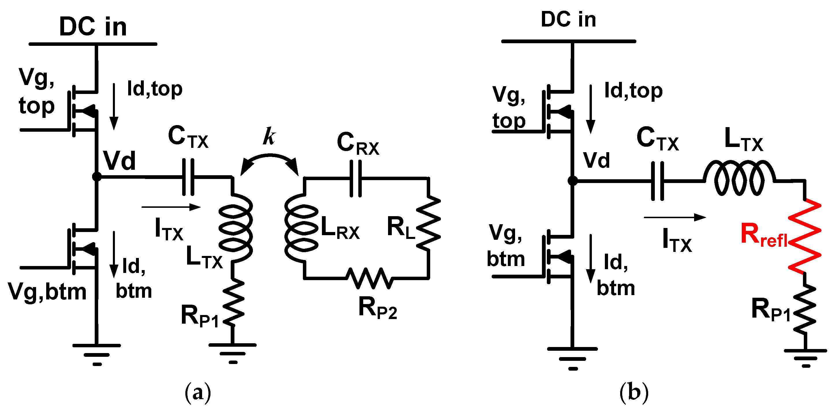
Figure 1a illustrates the circuit model of a basic wireless power transfer system. From the viewpoint of the transmitter, the coupling with the receiver can be represented by the reflected resistance,
Rrefl, in
Figure 1b where:
In other words, the current/voltage characteristic of
Figure 1a with receiver and coupling is equivalent to the current/voltage of
Figure 1b with the reflected resistance. It is important to recognize that the load resistor of Tx inverter is the reflected resistance.
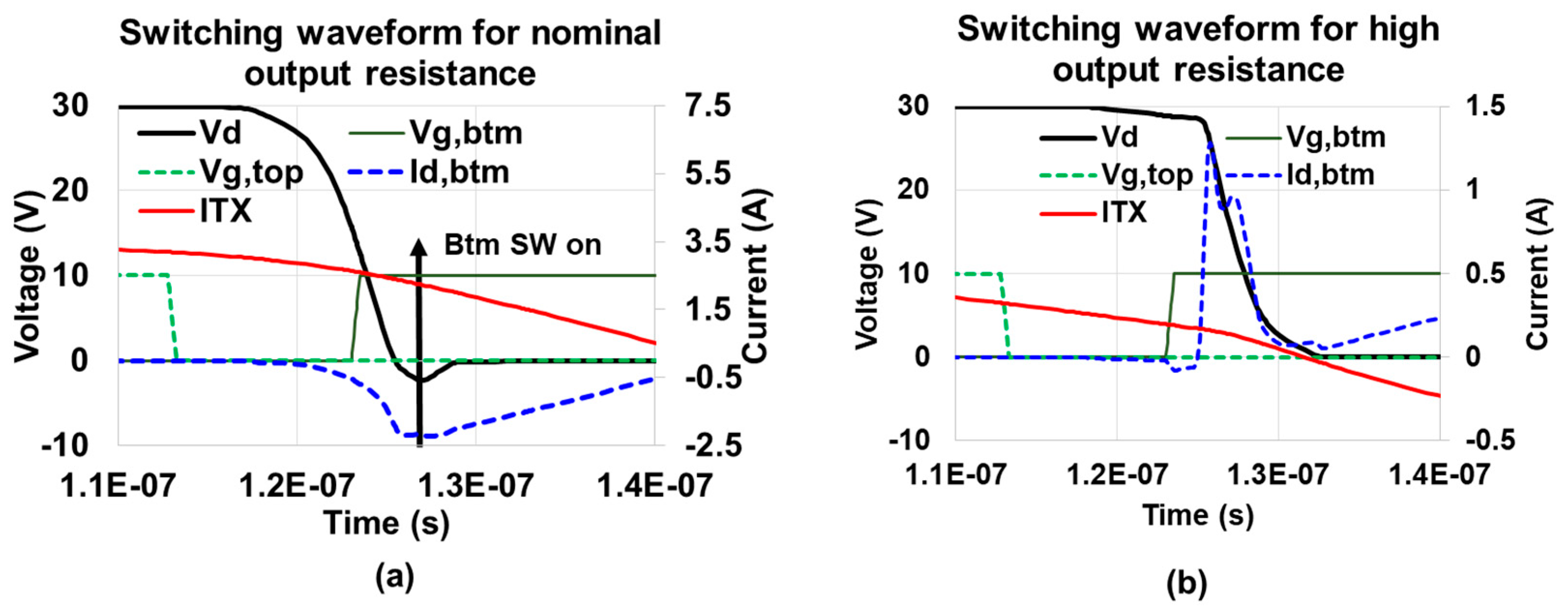
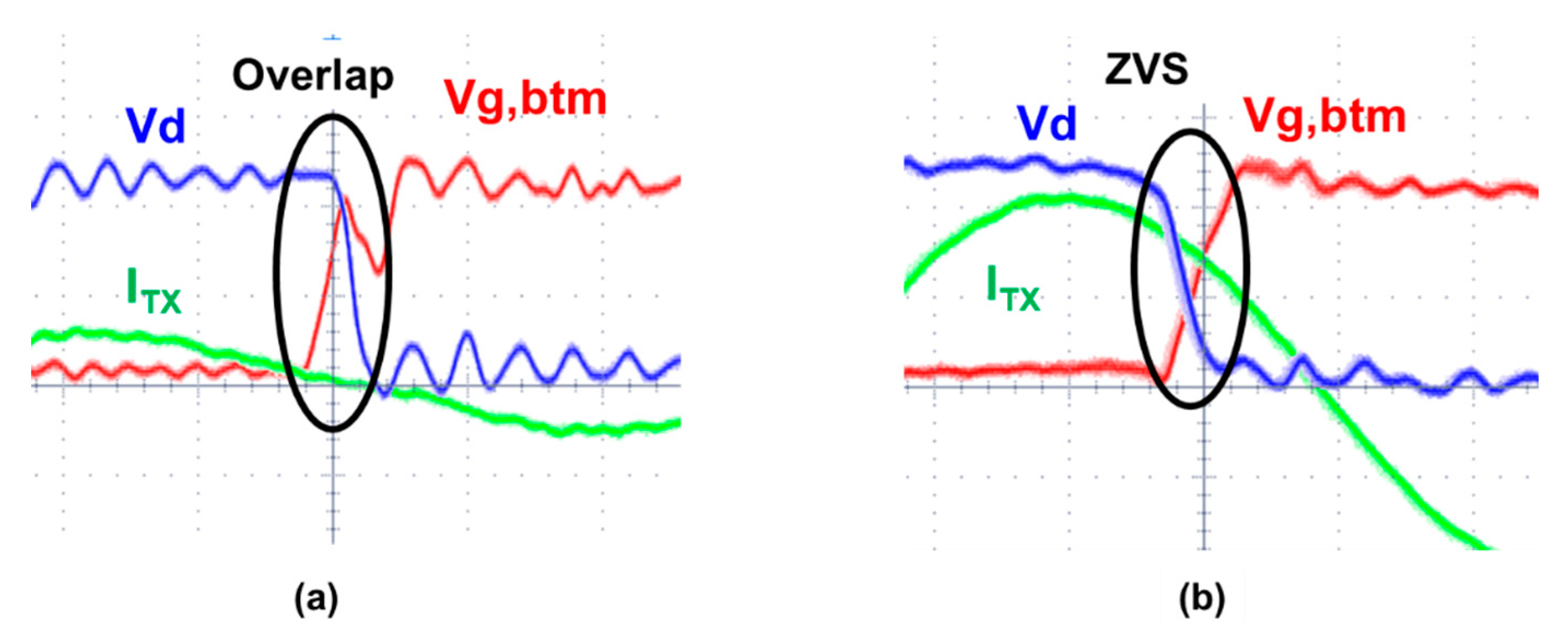
The normal zero-voltage switching (ZVS) waveform of inverter is shown in
Figure 2a. After
Vg, the upper limit is set to zero and both MOSFETs are off, the coil current (
ITX) discharges the parasitic drain capacitors of MOSFETs. This pulls down the drain voltage (
Vd) to zero when both MOSFETs are off. After that, the bottom MOSFET is turned on with very low drain voltage (
Vd). Therefore, switching loss is small in this case. The MOSFET used in this work is BUK9Y59-60E. Note that although
Vg,btm goes up at 123 ns, there is ~6 ns turn-on delay. Actual device turn-on point is approximately 128 ns.
However, this zero-voltage switching fails if the reflected resistance (
Rrefl) is too high [
11]. High reflected resistance happens when the coupling between Tx and Rx is high at close distance as in Equation (1). This reduces
ITX as in
Figure 2b. It then takes a longer time for the small
ITX to discharge the parasitic drain capacitance of MOSFETs. As a result, the
Vd voltage cannot drop to zero before the turning-on of the bottom MOSFET as in
Figure 2b, leading to switching loss [
11,
12,
13].
Another problem of high reflected resistance is the significantly reduced output power of Tx inverters. As the load resistor of a Class-D inverter becomes larger, the output power of the inverter is reduced according to the function
[
13].
3. Proposed Dual-Impedance-Frequency Operation
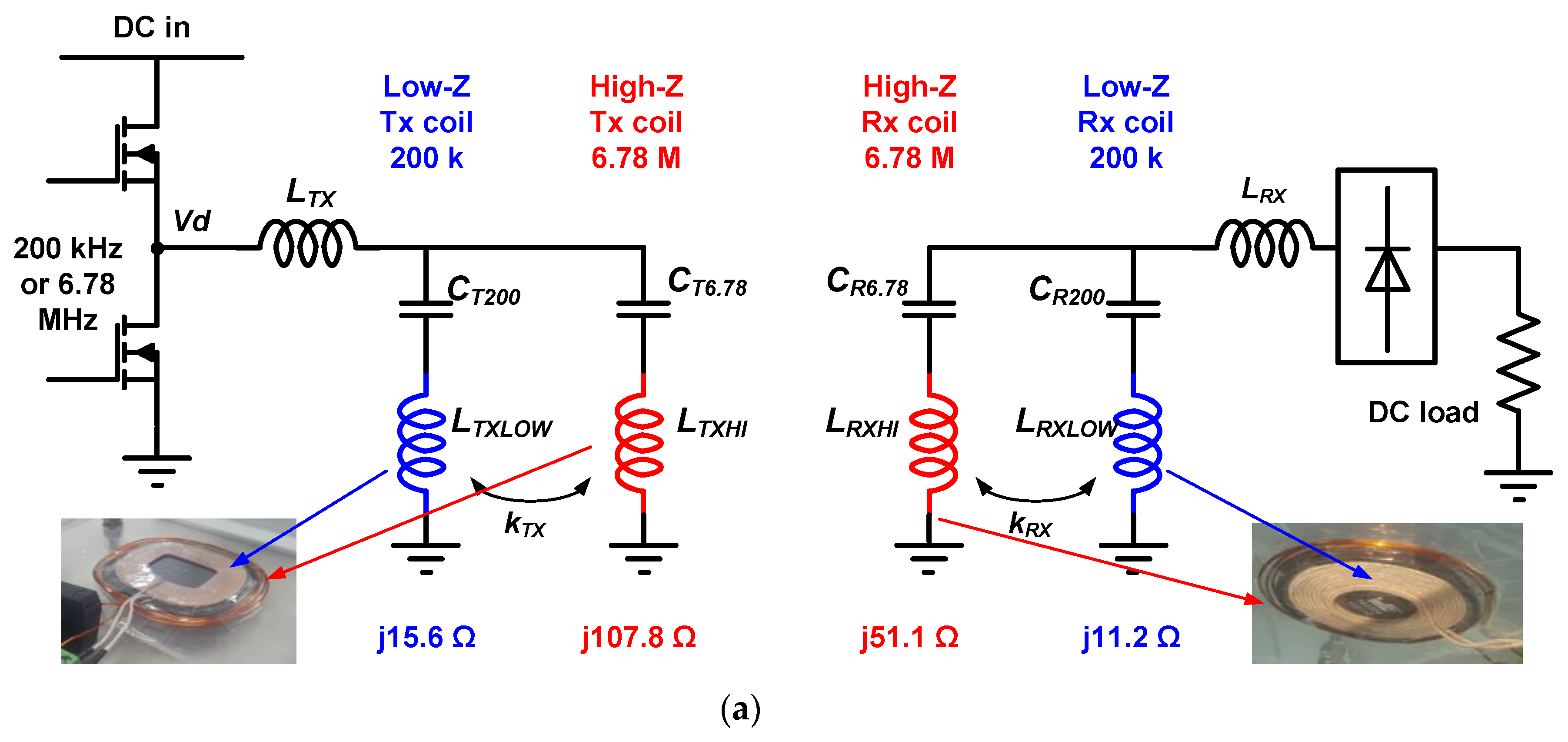
The discussion in the previous section indicates that the reflected resistance should be maintained at the appropriate level. Therefore, this paper proposes dual-impedance operation by dual-frequency capability as in
Figure 3a.
At a 200 kHz switching frequency, the current cannot flow toward LT(R)XHI because high-Z coils are tuned at ~6.78 MHz and behave as a large capacitive impedance at 200 kHz. Specifically, the impedance looking at a high-Z coil is . At 6.78 MHz, the magnitude of ωLHI and 1/(ωC6.78) is comparable and thus they cancel each other out. However, for operation with low ω frequency (200 kHz), the ωLHI term disappears whereas the 1/(ωC6.78) term becomes enlarged. Hence, the total impedance becomes approximately , which is capacitive. On the other hand, at a 6.78 MHz switching frequency, the currents cannot flow toward LT(R)XLOW because it behaves as large inductive impedance at 6.78 MHz switching frequency. The impedance looking at a low-Z branch which is tuned for 200 kHz is . At 200 kHz, the magnitude of ωL and 1/(ωC) are comparable and cancel each other. However, when ω becomes high (6.78 MHz), the 1/(ωC200) term disappears whereas the ωL term becomes enlarged. Hence, the total impedance becomes approximately , which is inductive.
Therefore, the proposed coil enables dual-band operation without dedicated capacitor-selection switches. Changing the inverter driving frequency is enough for mode selection. The selected frequency bands are compatible with existing standard specification and frequency regulations. 200 kHz belongs to the Qi specification standards [
14]. 6.78 MHz is the Industrial, Scientific and Medical (ISM) band which can be freely used [
15], an example of which is AirFuel standards [
16].
A method of adjusting coil impedance was proposed in [
17]. However, this requires the coil to be split into many segments, and each segment should be connected to each relay switch. Another method of impedance reconfiguration is to use multiple capacitors and relay switches [
9,
18]. The drawback of these schemes is the use of relay switch. The solid-state relay in [
17] can withstand only 0.2 W of power. Although mechanical relay switches can withstand higher power, its volume is too large, and its response time is slow. Moreover, a mechanical relay has a short lifetime and generates clicking sounds during operation. MOSFET or IGBT switches that are common in power electronics cannot be easily used to reconfigure resonant networks because the current at the resonant capacitor or coil is bi-directional. The intrinsic antiparallel diode within MOSFET or IGBT allows current flow from source (emitter) to drain (collector) terminal even if gate input is off. Two MOSFETs (IGBTs) should be connected in series with back-to-back configuration to block the bi-directional resonant current [
19]. This increases the losses in switch and requires an additional isolated gate driver.
The proposed method can handle high power without mechanical switches. Although two coils are used, the increment of volume is minimal because one coil is placed within the other coil concentrically.
The coil impedance is designed such that it is high at 6.78 MHz mode and low at 200 kHz. Hence, the coil impedance is adjusted by simply selecting the operating frequency. When the coupling k becomes low, the reflected resistance drops as in Equation (1). However, Equation (1) implies that the reflected resistance can be high if
is high even with the small coupling
k. Therefore, the high-Z coils are activated by operating at 6.78 MHz. When the coupling k becomes too high, the reflected resistance becomes excessively high, resulting in the degradation of inverter efficiency as in
Section 2. To prevent excessive rise of reflected resistance, small
is activated by 200 kHz switching frequency mode.
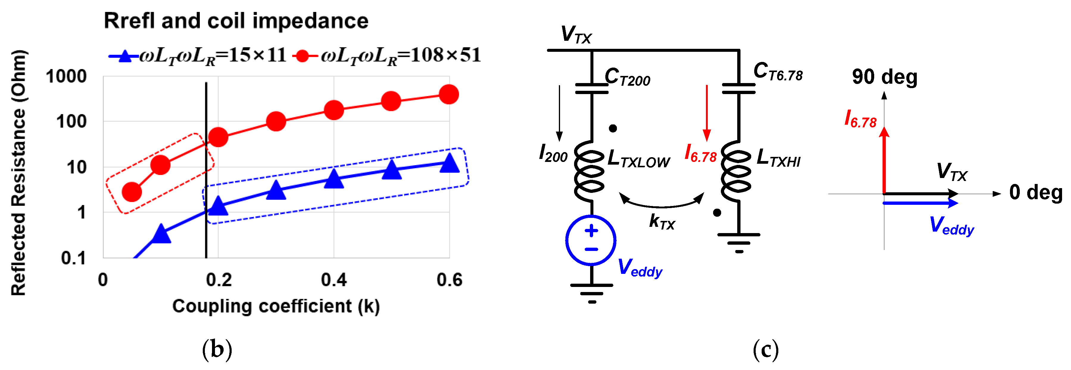
Referring to
Figure 3b, the target range of reflected resistance,
Rrefl, is set to 1–30 Ω because, within this range, the inverter efficiency remains at least 84% or higher. This range of
Rrefl should be maintained across the whole operating distance of 0.5–4.4 cm, within which the coupling coefficient
k varies from 0.057 to 0.6. For the blue triangular trace (low-Z coil) of
Figure 3b, its reflected resistance drops below 1 Ω when the coupling
k is lower than 0.17. At this low-coupling region, the red circular trace (high-Z) can lift the reflected resistance to 30 Ω. To this end, the high-Z coil is designed such that the multiplication of TX impedance and RX impedance of high-Z is 30 times higher than the multiplication of low-Z TX and RX impedances. The TX sector and the RX sector can have different impedance values—this does not affect the proposed design method. The RX is usually a movable device, and hence it is designed with smaller geometry and resultant lower impedance.
One practical issue is that, because
LT(R)XHI and
LT(R)XLOW are placed concentrically each other, high coupling between them exists,
kTX and
kRX. This coupling may cause an eddy current at
LT(R)XLOW during 6.78 MHz switching frequency mode. To avoid this eddy current,
CT(R)6.78 is designed to be smaller than a value which would completely cancel the
LT(R)XHI impedance [
20]. Referring to
Figure 3c, phasor diagram, the
I6.78 phase is faster than
VTX by 90 degree if
CT6.78 is chosen to be smaller than a value that resonates L
TXHI. From the dot convention and mutual inductance equation, the
Veddy is given as
, which becomes in-phase with
VTX. Therefore, the voltage difference across
LTXLOW-CT200 is zero, which prevents eddy current. This allows closer placement of low-frequency coil and high-frequency coil each other than the coils of [
21].
4. Measurement Result
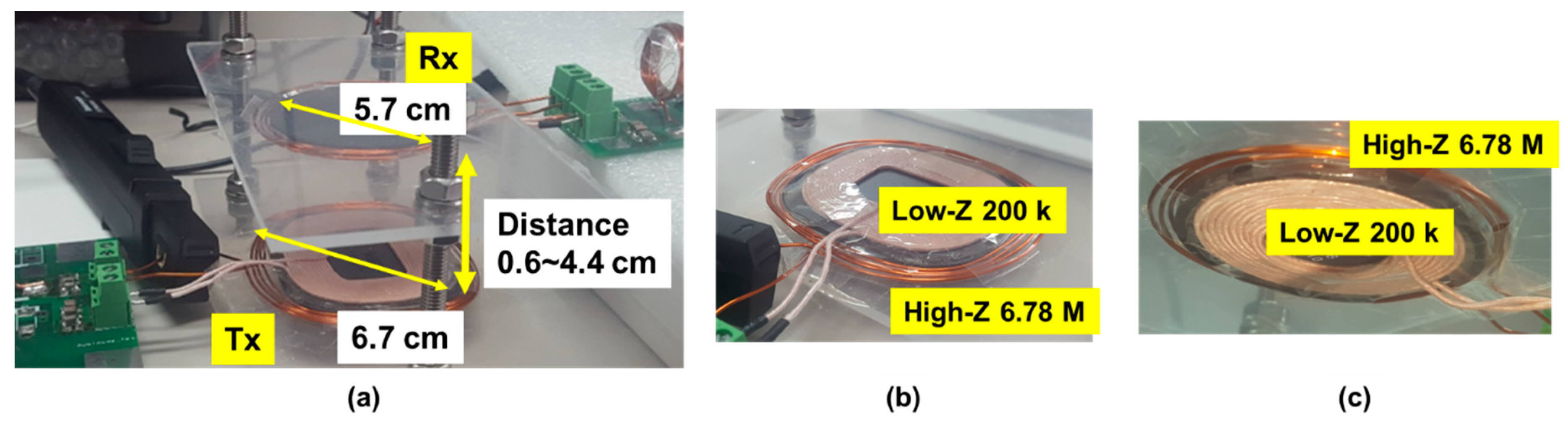
Figure 4 shows measurement setup. The
LTXHI and
LRXHI are 2.53 μH and 1.2 μH and the
LTXLOW and
LRXLOW are 12.4 μH and 8.92 μH, respectively. The
CT200 and
CT6.78 are 55 nF and 130 pF, respectively. The
CR200 and
CR6.78 are 64.1 nF and 252 pF, respectively.
The distance between Tx and Rx varies from 0.6 cm to 4.4 cm. The corresponding coupling variation is from 0.6 to 0.057. The receiver output is 12 V–2 A, 24 W.
Figure 5 demonstrates the problems of excessively high reflected impedance.
Figure 5a is the measured voltage and current waveform when the distance is only 1.1 cm and the reflected resistance is too high. The
ITX is suppressed due to high impedance, thereby causing longer delay for
VD to reach zero. The bottom MOSFET is turned on before
VD drops to zero, causing severe switching loss. On the other hand, the
ITX at 2.9 cm distance of
Figure 5b is moderate and
VD can drop to zero before the bottom MOSFET is turned on. Zero-voltage switching is achieved in this case.
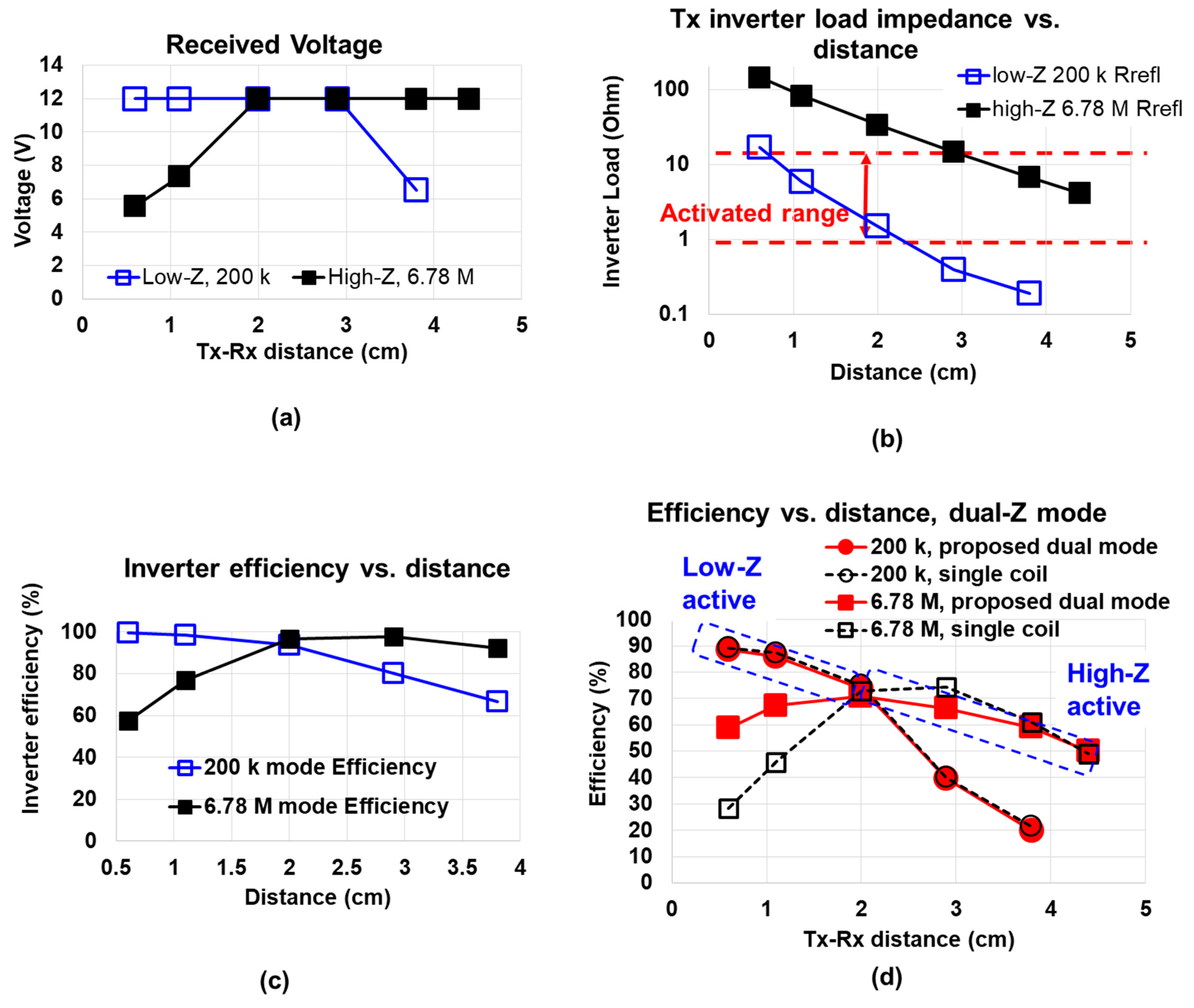
Figure 6a shows the measured efficiency and received voltage for the standalone single impedance system. The standalone single impedance system refers to the conventional single-frequency single-coil system. It is apparent that a single configuration cannot accommodate full distance range. Specifically, low-Z mode is better for 2 cm and below while high-Z performs better above 2 cm. The high-Z mode cannot output the required 12 V because of the excessive reflected resistance seen by the inverter.
Figure 6b presents measured reflected resistance (i.e., inverter load) for standalone 200 kHz low-Z and 6.78 MHz high-Z configurations. At 1.1 cm and below, the inverter load resistor is too high. By introducing low-Z mode, the inverter load can be managed within 30 Ω.
Figure 6c shows inverter efficiencies. At 3–4 cm 200 k mode, the inverter load (reflected resistance) is too small, causing efficiency to drop. At 0.6–1.1cm 6.78 MHz mode, inverter efficiency is degraded due to excessively high reflected resistance and ZVS failure. This is supported by
Figure 5a,b.
In
Figure 6d, it is proved that the two different standalone impedances are successfully merged into one dual-impedance system using
Figure 3, because the efficiency degradation from standalone circuit to dual-impedance system is minimal. In a real usage scenario, the low-Z is activated simply by driving the Tx inverter to 200 kHz when reflected impedance becomes high, while the high-Z is activated by 6.78 MHz driving the inverter when reflected resistance becomes low.
One possible shortcoming of the proposed method is the parasitic resistance from L
TX and L
RX inductors. However, other matching techniques such as mechanical relays also cause parasitic resistance. Moreover, in
Figure 6, at the longest distance (4.5 cm), the efficiency with the proposed method is the same as the efficiency of a single-mode coil. That means, the efficiency did not degrade due to the dual-mode capability.
5. Conclusions
A frequency-controlled dual-impedance operation which prevents excessive variation of inverter load is proposed. The low-impedance coils or the high-impedance coils are selected depending on coupling condition simply by frequency selection. This contrasts with the conventional impedance matching which relies on mechanical relay switch arrays to select capacitor bank or coil snippet.
The increment of coil volume is kept minimized by packing one coil within the other coil. The proposed method obviates the necessity of any impedance tuning switches—such as mechanical relays and back-to-back series semiconductor switches—which cause losses and high volumes. In summary, a compact, high efficiency, and mechanical-part-free method of impedance reconfiguration in response to coupling variation is realized.
Increasing the number of coils and frequency bands is not feasible at this moment because of the eddy current. For two coils in this paper, it is easy to prevent the eddy current following the scheme of
Figure 3c. However, it is not directly applicable to more than 3 coils. Triple-band systems with eddy current blocking capability will be a topic for further research.


