Article

Energy-Efficient Wireless Hopping Sensor Relocation Based on Prediction of Terrain Conditions

1
Department of Electrical Engineering, Incheon National University, Incheon 22012, Korea
2
Department of Liberal Arts, Seoul Theological University, Bucheon 14754, Korea
*
Author to whom correspondence should be addressed.
Electronics 2020, 9(1), 49; https://doi.org/10.3390/electronics9010049
Submission received: 9 December 2019 / Revised: 23 December 2019 / Accepted: 26 December 2019 / Published: 28 December 2019
(This article belongs to the Special Issue Wireless Power/Data Transfer, Energy Harvesting System Design)

Abstract

:
It is inevitable for data collection that IoT sensors are distributed to interested areas. However, not only the proper placement of sensors, but also the replacement of sensors that have run out of energy is very difficult. As a remedy, wireless charging systems for IoT sensors have been researched recently, but it is apparent that the availability of charging system is limited especially for IoT sensors scattered in rugged terrain. Thus, it is important that the sensor relocation models to recover sensing holes employ energy-efficient scheme. While there are various methods in the mobile model of wireless sensors, well-known wheel-based movements in rough areas are hard to achieve. Thus, research is ongoing in various areas of the hopping mobile model in which wireless sensors jump. Many past studies about hopping sensor relocation assume that all sensor nodes are aware of entire network information throughout the network. These assumptions do not fit well to the actual environment, and they are nothing but classical theoretical research. In addition, the physical environment (sand, mud, etc.) of the area in which the sensor is deployed can change from time to time. In this paper, we overcome the theoretical-based problems of the past researches and propose a new realistic hopping sensor relocation protocol considering terrain conditions. Since the status of obstacles around the sensing hole is unknown, the success rate of the hopping sensor relocation is used to predict the condition of the surrounding environment. Also, we are confident that our team is uniquely implementing OMNeT++ (Objective Modular Network Testbed in C++) simulation in the hopping sensor relocation protocol to reflect the actual communication environment. Simulations have been performed on various obstacles for performance evaluation and analysis, and we are confident that better energy efficiency with later appearance of sensing holes can be achieved compared to well-known relocation protocols.

1. Introduction

Recently, there have been active studies for big data analysis using networking to collect, process, and analyze a large amount of data [1]. In order to not only collect various data but also fast process information, the technologies of collecting and transmitting data have emerged as a very important issue. Here, there is no doubt that the transmission technology among wireless sensors is important for big data technology. Research on various wireless sensor networking technologies to transmit the collected data has been actively conducted for decades [2,3].
A lot of wireless sensors are properly distributed through the observation area to collect the interested data [4,5]. It is not difficult to distribute the sensors to accessible areas to human, however unmanned mobile devices (unmanned air vehicle, drone, etc.) could be used in large inaccessible areas. After deploying the sensors, let us consider that data collection occurs frequently in particular area. There is an inherent problem that a small sensor has limited energy. To remedy this power limitation, wireless charging systems for IoT sensors have been researched actively recently [6]. However, charging system for the sensors is not always available, especially in inaccessible area like rugged terrain. Thus, it is necessary that the sensor relocation protocol to recover sensing hole employs energy efficient scheme as a preemptive measure. Some sensors may be quickly drained of energy while continuously collecting and transmitting data in the particular area. This case is called a sensor node failure, the communication of the entire network may be disconnected, and the desired data could not be collected in the worst case. The particular area, where a certain number of sensors become faulted and cannot collect the interested data anymore, is called as a sensing hole [7]. In order to prevent a sensing hole occurred, various studies such as schemes of minimizing energy consumption by adjusting the active/idle states and energy efficient routing protocols have been conducted [8,9,10]. Although the energy limit of the sensor node can be reduced by various applications, it is impossible to solve the sensor node failure problem completely. Therefore, it is necessary to recover it by moving other sensors to the sensing hole occurred, as the most realistic solution. For this reason, researches on mobile sensors have received a lot of attention. The failure sensors depleted of energy could be replaced by mobile sensors moved from other area. The authors of [11] considered a case that a wheel-based mobile node could temporarily replace the role of a fixed node by moving if a fixed sensor node is failed in the interested area. However, there are limitations in the migration of wheel-based sensors. In other words, energy consumption has to be further considered in order to move, however wheel-based movement is essentially inadequate in very rough areas.
In order to overcome the limitation of wheel-based mobility, a hopping-based moving model is introduced. A hopping-based sensor node is bionically designed to jump itself, like a frog. For example, a mobile unit implemented by DARPA (Defense Advanced Research Projects Agency, USA) is able to do up to 100 jumps with one full fuel injection and jump up to 10 m high [12,13]. The paper [14] by MSU (Michigan State University, USA) describes the performance comparisons for the maximum jump height, jumping distance, and so on for various jumping robots, in detail. Researches on not only the implementation of jump-based mobility but hopping sensor relocation algorithm to recover the sensing holes that occurred, have been actively conducted [15,16,17,18]. However, most of studies so far require that every cluster header sensor node has to know all information for the current whole network area and set up routes to supply/request hopping sensors to recover sensing holes occurred. In fact, no matter how small the observation field to obtain interested data is, the exchange of information and establishment of paths among the cluster header sensors are difficult in real world, and involve a storm of numerous control messages. Recently, our research team has solved these problems drastically [19]. First of all, every cluster header does not need to know all information of other cluster headers or all networks. It is a distributed networking-based relocation protocol that recovers a sensing hole by simply requesting necessary sensor nodes from neighbor cluster headers. A cluster header node selects appropriate hopping sensors based on information communicated among all sensor nodes in its cluster, and they are moved to the requesting neighbor cluster. Up to now, however, most relocation protocols have assumed that the observation fields, in which mobile sensors are scattered, are ideal environments. In other words, the areas where sensors move are likely to be irregular, under the existence of obstacles like stones or mud. Reference [18] is the first study of hopping sensor relocation based on probabilities of existence of obstacles, however there is a limitation that the assumption that every cluster header sensor grasps all information of rugged terrains in all regions is not very realistic.
In this paper, a novel relocation protocol that considers the probabilities of the level of obstacles using the information of success rate for migration is proposed. Here, it is not necessary for each cluster header sensor node to know all information of entire network; the cluster header only knows the information such as the probabilities between neighbor clusters. In addition, as far as we know, it can be very meaningful to have the first realistic simulation with OMNeT++ [20], similar to the actual environment.
The rest of this paper is organized as follows. Section 2 summarizes the mobility model of hopping sensor and the related relocation protocol. In Section 3, the proposed relocation protocol is explained along with the scenario in detail. The simulation results are analyzed in Section 4, and Section 5 concludes this paper.

2. Previous Work

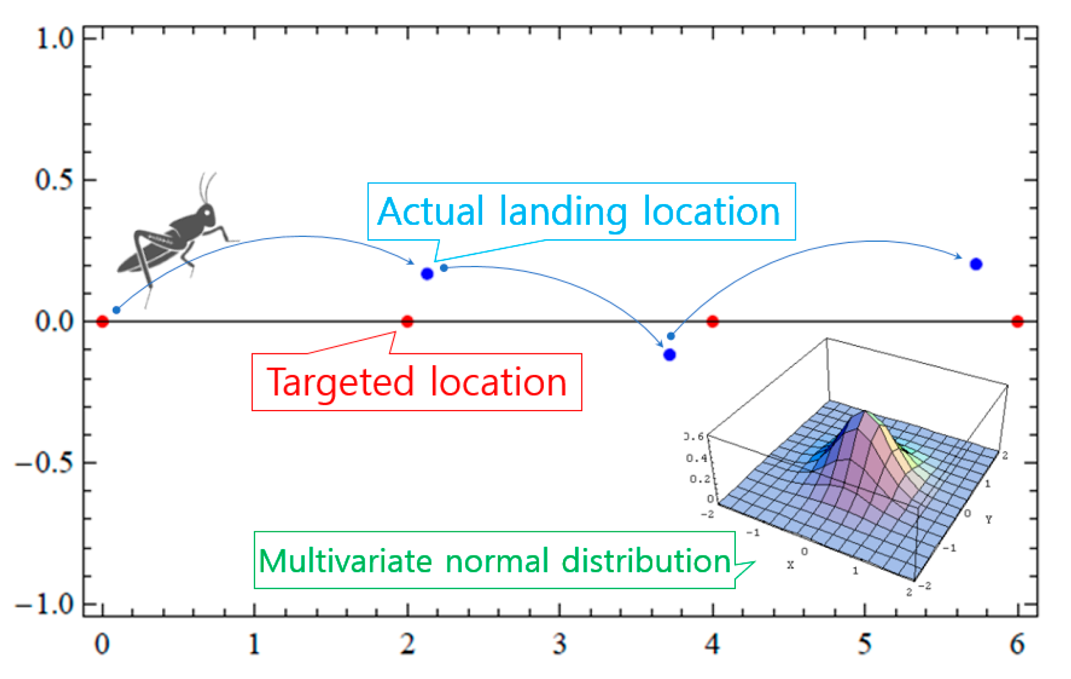
2.1. Characteristics and Movement Models of Hopping Sensors

Typical mobile sensors are based on wheels. This structure has the disadvantage that it is very difficult to move in rough terrain such as gravel, sand, and so on. In order to overcome the mobility problem, hopping sensors that mimic movements such as a grasshopper or a frog have been devised. In addition, the hopping sensor enables communication among sensor nodes in environments where it is difficult for a sensor to communicate each other because the distance between sensor nodes is farther than a normal communication radius of a sensor, or where there are various obstacles which block communication propagation. Up to now, various researchers have shown that the connectivity between hopping sensors could be improved by the jumping of each hopping sensor. The papers [21,22] have shown that the communication radius is increased about six times compared to the one on the ground when a hopping sensor jumps 1 m from the ground. The paper [23] actually implemented a hopping sensor using a separate launcher for jumping and measured the transmission radius varied according to the height of the jump. The changed transmission radii were compared with the results of [21], and it was confirmed that they had similar results.
Compared to a wheel-based sensor node, a hopping sensor, which is moving on jump, might be inherently less accurate to migrate to the desired area. In fact, it would be more desirable to have a positive explanation for enabling movement in an environment that cannot be moved with wheels, rather than a negative idea that movement accuracy is poor. The paper [15] first attempted a performance analysis of how a hopping sensor node was affected by wind when jumping and moving. It is obvious that the movement of hopping model is more vulnerable to air resistance than that of wheel-based model. Mathematical modeling of this hopping movement can be explained as follows.
As shown in Figure 1, the hopping sensor does not land exactly the targeted location (T) after jumping, and it is more likely to land near it (i.e., actual landing location; L). Let the variables T and L be vectors of the target and actual landing locations. The error vector D with respect to the difference between the locations can be expressed as LT. Here, we assume that D follows the two-dimensional standard normal distribution with means (0, 0), standard deviations (σx, σy), and correlation ρ. The probability density function can be defined as
f X Y = 1 2 π σ x σ y 1 ρ 2 e 1 2   ( 1 ρ 2 ) ( x 2 σ x 2 + y 2 σ y 2 2 ρ x y σ x σ y )
Let us consider that the hopping range is 2, standard deviations are 0.3, and the correlation is zero. The movement of the hopping sensor is as shown in Figure 1. The movement of the red circle is an ideal movement, but the movement of the blue circle is a movement that reflects the mentioned constraints. It can be easily seen that the movement of the blue circle more appropriately reflects the movement in rough environment suitable for the hopping sensor than that of the red circle. Therefore, the above error vector of the movement would be preferably applied to the simulation in Section 4.

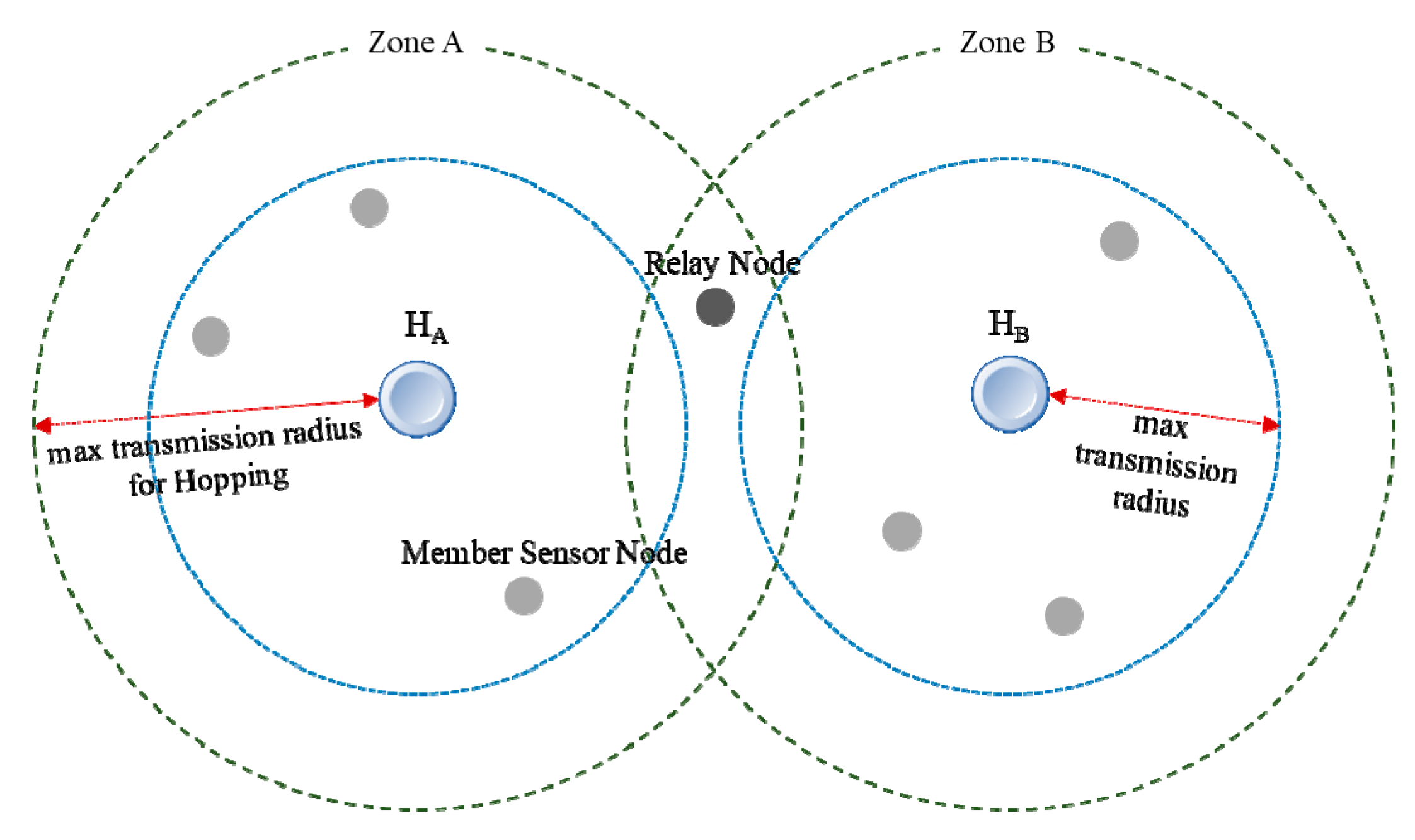
2.2. Basic Assumptions about Hopping Sensors and Relocation Protocol

In the traditional research fields of wireless sensor networks (WSNs), there are various methods for clustering and cluster header selection of sensor nodes randomly distributed in the interested areas [24]. In fact, since the purpose of this paper is to study the relocation of hopping sensor nodes, it is assumed that the clustering and selection of the cluster headers have already been completed by various existing methods. For example, hopping sensor nodes are randomly scattered firstly on the interested area in which we want to collect data. After that, the area is divided by an appropriate clustering algorithm, and a cluster header node is selected for each cluster zone. The cluster header periodically communicates with member sensor nodes in its cluster zone, and it manages representative information of each member. Considering the network connectivity problem, communication between each cluster header and all member sensor nodes could jump to send and receive messages with its maximum transmission radius. Moreover, every hopping sensor node contains a GPS unit capable of knowing its current location [25].
The terms used in this paper are explained in Figure 2. Every hopping sensor node can be either a cluster header node or a member sensor node. Since the maximum transmission radius is defined as a cluster zone when the cluster header maximally jumps, there is a high possibility that direct communication between the cluster headers could be impossible. However, some member sensor nodes in the area intersecting with the cluster zones (that is, near the maximum transmission radius of each cluster header) may communicate with two or more cluster headers. This hopping sensor node is called as a relay node, and the role of the node could help to facilitate communication between cluster headers [18].
Unlike hopping sensor relocation protocols, which were only theoretically studied, the paper [19] proposed a relocation protocol suitable for a distributed environment so that it could be applied to a real environment. The protocol proposed in the mentioned paper is briefly summarized using an example in Figure 3. If the cluster zone C is a sensing hole, the protocol strategy to recover the problem is as follows.
Step 1. The cluster header HC sends a REQ message requesting one hopping sensor to the relay node R2.
Step 2. The relay node R2 forwards the REQ message received from HC to the cluster header HB of the cluster zone B.
Step 3. The cluster header HB sends a MOVE message for moving to neighbor cluster zone C to the hopping sensor M3 selected as a moveable member in its zone B.
Step 4. At the same time, the cluster header HB predicts that its zone could also be a sensing hole, and it sends a REQ message for requesting one hopping sensor to relay node R1.
Step 5. The relay node R1 forwards the message REQ to its another cluster header HA.
Step 6. The cluster header HA chooses M2 among hopping member sensor nodes of its zone A in its zone and commands the movement. As a result, one sensor is properly allocated to each cluster zone, and the sensing zone (cluster zone C) could be recovered.

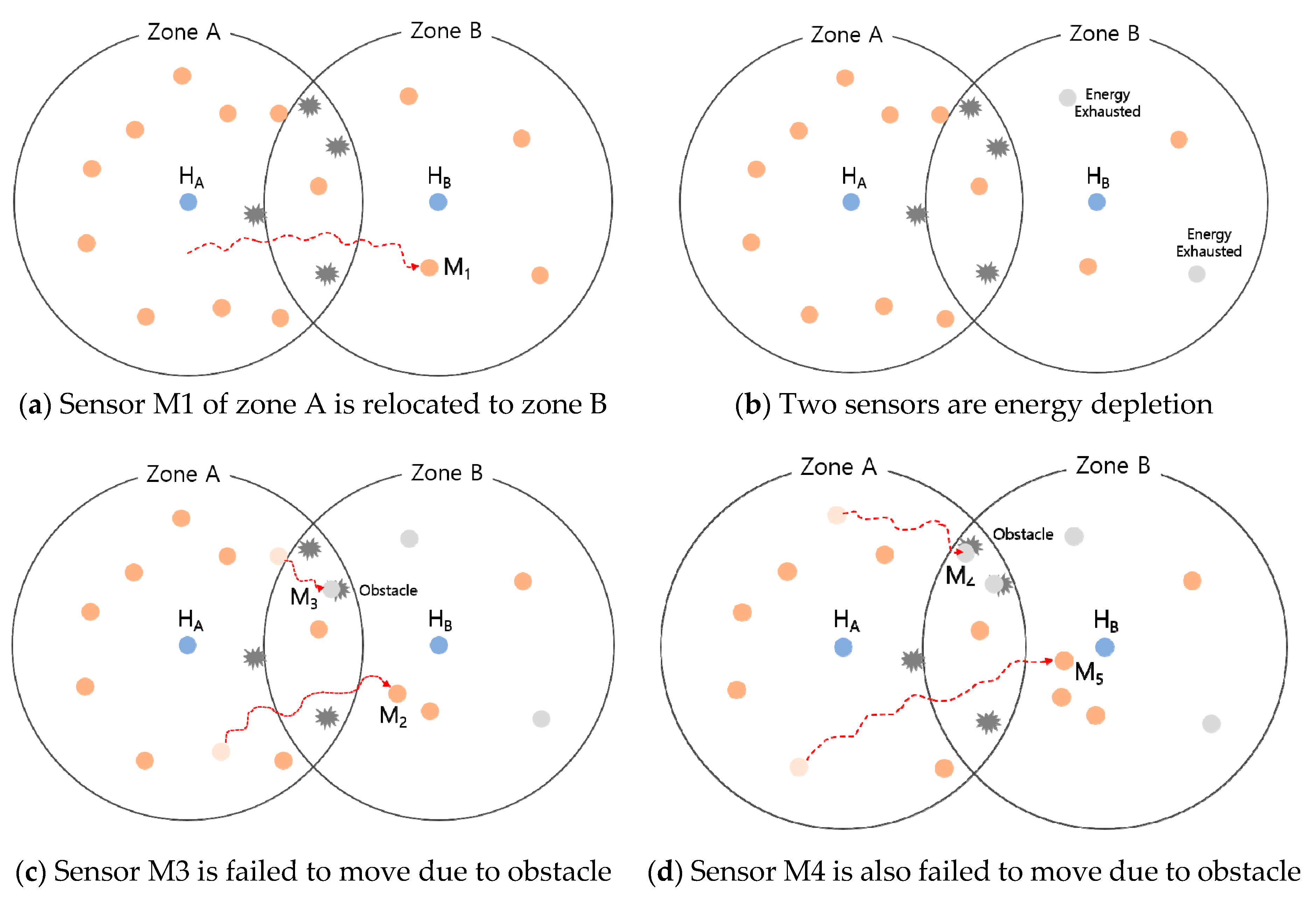
3. The Proposed Relocation Protocol for Rugged Terrains

Although the distributed-based relocation protocol [19] has made up for the drawbacks of the previous central-based relocation protocols, questions still remain whether it is suitable for the real world. In fact, it should be noted that the environment in which hopping sensors are deployed would be different from the general terrain. In the relocation protocol [19], topographical information on obstacles around the cluster zones were not taken into account. The movement of hopping sensors fails due to obstacles and the relocation cannot satisfy the movement requested from the cluster header of sensing hole. Thus, the number of messages continuously requested may increase to overcome the persisting sensing hole. This could put a heavy load on the entire network, and it would be very negative in terms of energy. Therefore, we propose a relocation protocol for more realistic hopping sensor networks by indirectly predicting the topographic information around sensing holes.

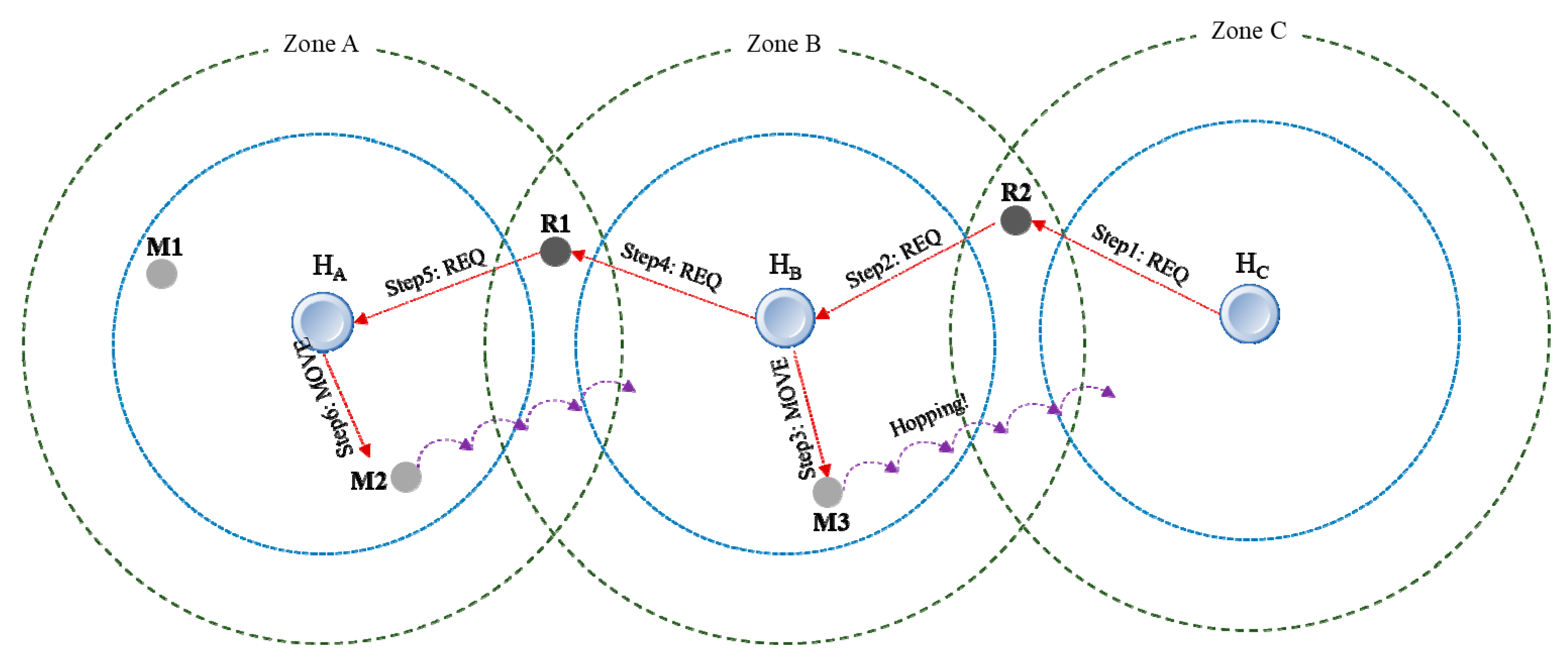
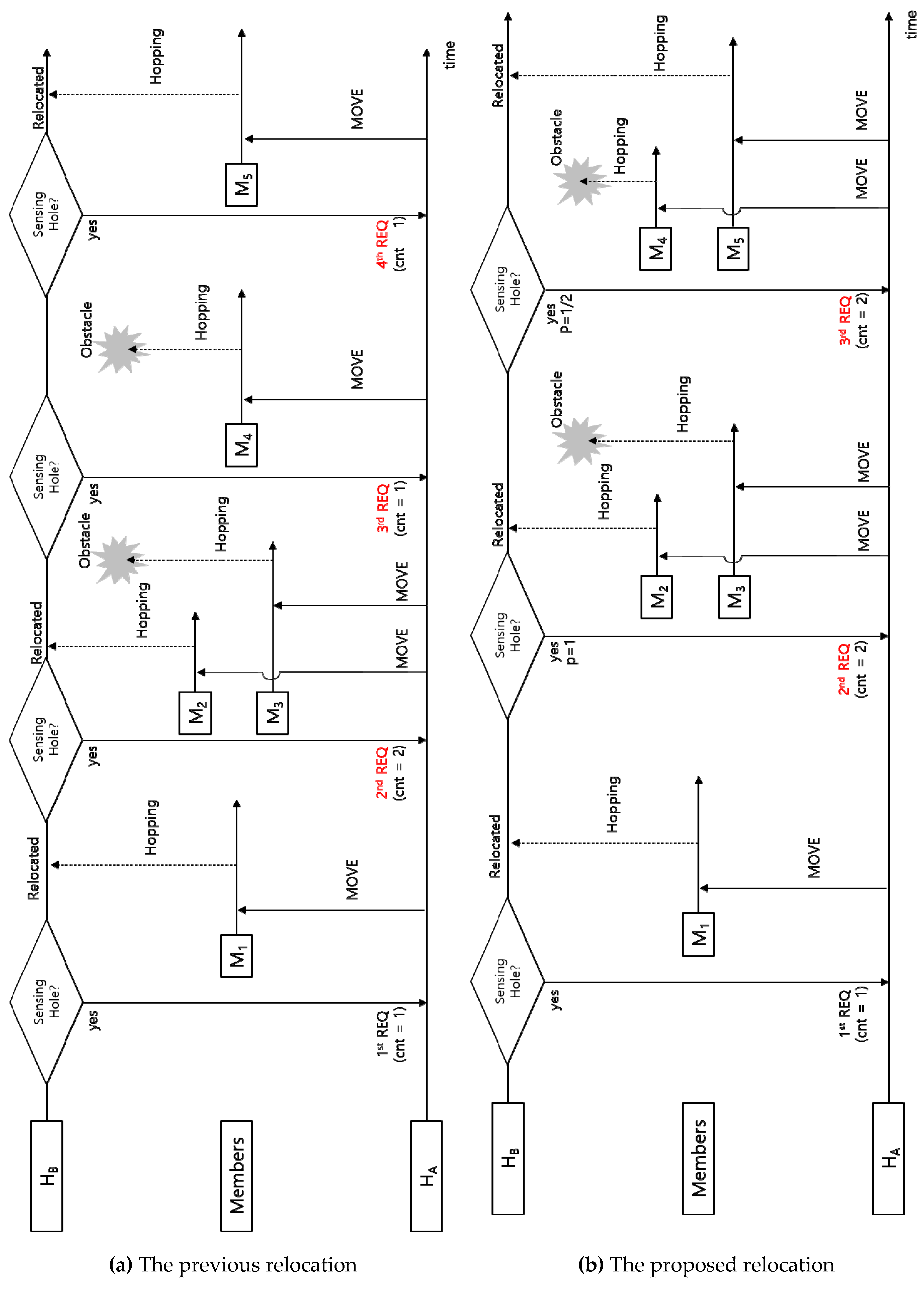
3.1. Basic Operation of the Proposed Relocation Protocol

In this section, we propose a novel relocation protocol that takes into account the environment surrounding the sensing hole occurred. Figure 4 shows the message flows between hopping sensors that the types are cluster header, relay node, and member sensor node. The detailed formats of the messages for the proposed relocation protocol and the message flows for each sensor node are described in detail as follows.
Step 1: The cluster header of the cluster zone A periodically broadcasts a HELLO message inside its zone to identify member sensor nodes. If a member node receives HELLO for the first time, the source address of the received HELLO message is memorized as its cluster header.
HELLO: = {message type, source address, destination address (broadcasting)}
Step 2: The member that received the HELLO message responds to the cluster header with a HELLO-ACK message to notify its health. If different HELLO messages are received from several cluster headers in Step 1, the member node is aware of that it has become a relay node for each cluster header. Thus, it also indicates whether a relay node or not, when the HELLO-ACK message is replied.
HELLO-ACK: = {message type, source address, destination address, relay node? (T/F)}
Step 3: The cluster header determines whether or not, currently, its zone is a sensing hole using the number of addresses of HELLO messages received. In the case of a sensing hole, the cluster header sends a relay message to all its relay nodes.
RELAY: = {message type, source address, destination address (multicasting)}
Step 4: As soon as the relay nodes receive the RELAY message, they send a RELAY-ACK message back to the cluster header. The cluster header may sequentially receive several RELAY-ACK messages. Among them, the relay node of the RELAY-ACK message, which is first received at the cluster header, is selected and other RELAY-ACK messages are ignored. Also, if a relay node overhears a RELAY-ACK message from another relay node while preparing to send a RELAY-ACK message, it immediately stops sending its message.
RELAY-ACK: = {message type, source address, destination address}
Step 5: So far, the cluster header is able to detect that a sensing hole has occurred (Step 3), and it could choose a relay node to forward a message to the neighbor cluster header for requesting member hopping sensor nodes needed (Step 4). Here, the required number of members is the difference (TC) between the threshold value (T) to determine the sensing hole and the current number of members (C). However, the environment around the detected sensing hole may be rough terrain in reality, the sensing hole would continue because it might be high probability that the number of relocated hopping sensors is smaller than the requested number (TC). Therefore, the cluster header checks the numbers of previously requested members and successfully moved members and calculates the movement success rate (p = number of members successfully moved/number of members requested) of the surrounding environment for the current cluster zone. Here, the number of requesting member sensors (cnt) that can overcome the sensing hole can be calculated as follows.
cnt: = Ceiling[(TC) ∗ (1 + (1 − p))]
The cluster header sends a REQ message to the selected relay node.
REQ: = {message type, source address, destination address, cnt, sensing hole address, sensing hole GPS info.}
Step 6: When the relay node receives the REQ message from the cluster header of the sensing hole occurred, it forwards the received REQ message to another cluster header. Here, the source and destination addresses of the currently received REQ message are modified to its own address and the address of the another cluster header to be delivered, respectively.
Step 7: When the neighbor cluster header of the occurred sensing hole receives the REQ message forwarded, it broadcasts an ADV message to determine movable member hopping sensor nodes among the current members in its zone.
ADV: = {message type, source address, destination address (broadcasting) }
Step 8: Each member node that receives the ADV message sends an ADV-ACK message containing its current physical information to the cluster header.
ADV-ACK:= {message type, source address, destination address, some info.}
Here, above ‘some info.’ indicates several type of information for relocation strategy [19], including the current energy state, capability of hopping movement, GPS coordinate information, etc.
Step 9: The cluster header receives ACK messages and selects the appropriately movable hopping sensor nodes. Then, it sends MOVE message, which includes the location information about the sensing hole, to the hopping sensors selected.
ADV: = {message type, source address, destination address (multicasting), sensing hole address, sensing hole GPS info.}
Step 10: The member nodes receiving the MOVE message have to hop to the neighbor zone using the GPS information of the cluster header of the sensing hole. Here, as every hopping member is taking into account the usual transmission radius of the neighbor cluster header, it could calculate the coordinates of where to move properly. Thus, each member hopping sensor node no longer moves when the member node has moved as desired location.
Step 11: As mentioned in Step 1, the cluster header of the sensing hole broadcasts a HELLO message at periodic times. After a predetermined time, when the relocated member sensor node receives the new HELLO message, the member updates its previous cluster header information as the current one. If the relocated member sensor node receives multiple HELLO messages at this time, it would be changed to a relay node. In addition, each cluster header is able to update the current movement success rate p through the number of HELLO-ACK messages to properly reflect the level of obstacles. All hopping sensors have modules that can perform Steps 1 to 11 independently. Each module of a hopping sensor could be activated depending on whether it is currently playing a role of {cluster header, relay node, member sensor node}. This is summarized as follows.
Cluster header: = {Steps 1, 3, 5, 7, 9, 11}
Relay node: = {Steps 3, 4, 5, 6}
Member sensor node: = {Steps 2, 8, 10}

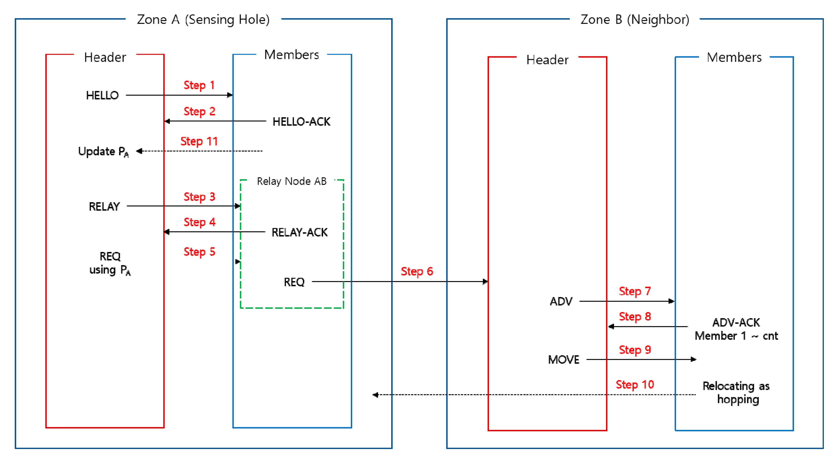
3.2. Descriptions of the Proposed Protocol

So far, most previous studies on hopping sensor relocation are central-based manner which each cluster header know all network information, but this is not a very practical study. The research of [19] only conducted a distributed-based approach to consider the realistic environment, but it still failed to take into account the surrounding obstacle information. That is, it is important to consider the environment using hopping sensors, not using the wheel-based ones. The following examples of simple scenarios in Figure 5 are described to understand the difference between cases reflected the surrounding obstacle information or not.
In Figure 5a, we assume that the cluster zone B has to maintain five member sensor nodes, except for the cluster header HB, for data collection. The cluster header determines that the sensing hole occurs when the number of members is smaller than 5. Here, the cluster zone B was a sensing hole due to a lack of one member (i.e., before moving M1). In order to recover the sensing hole, after the cluster header HB of zone B requests one member from zone A (the first REQ), the member sensor node M1 of zone A moves to zone B.
In the first scenario, let us consider the relocation of hopping sensors without taking into account obstacles as mentioned previous literatures. In Figure 5b, two member sensor nodes fail due to energy exhausted in the cluster zone B. The cluster header HB is aware of the state of sensing hole, and it requests two members from the neighbor cluster zone A (the second REQ). Two members, which were ordered to move to the cluster zone B, are moving as shown in Figure 5c. One member M2 is successfully moved to the cluster zone B, while the other M3 is failed to move due to obstacle. The cluster header of the cluster zone B perceives the state of sensing hole again, and it requests one member from the cluster zone A (the third REQ). In Figure 5d, since the selected member M4 fails to move because of unexpected obstacle, the cluster zone B is still a sensing hole. In order to overcome the sensing hole, the cluster header HB requests one member from the cluster zone A repeatedly (the fourth REQ). The member M5 is successfully moved, and the sensing hole is finally recovered.
In the second scenario, let us take into account the relocation based on probabilities of existence of obstacles. In Figure 5b, the cluster header HB should recognize the state of the sensing hole and request some members from the neighbor cluster zone A. First of all, let the initial value of the movement success rate p be 1. The success rate p is used to calculate the requested number of member sensors. According to Equation (2), the number of the requested members is 2, Ceiling[(5 − 3) ∗ (1 + (1 − 1))], the cluster header HB requests two members from the cluster zone A (the second REQ). In Figure 5c, the cluster header HA commands two members to move to the cluster zone B. As described in the above first scenario, one member M2 moves successfully, but the other member M3 fails to move due to the obstacle. Thus, the cluster header HB updates the value of p as 1/2, and it is also aware of the sensing hole. The cluster HB calculates the number of requesting members using Equation (2), Ceiling[(5 − 4) ∗ (1 + (1 − 1/2))], so two members are requested to the cluster HA (the third REQ). One of the two members of A, the member M3 fails to move to the zone B, as in the first previous scenario. However, the other member M2 can successfully move to the zone B to overcome the state of sensing hole.
As we are looking at the mentioned two scenarios, it might be thought that the probability of successful movement represents the state of obstacles between cluster zones. Therefore, it is a good example to see that the use of the above probability could reduce the number of request messages, when the cluster header of sensing hole is requesting members to the neighbor zones. Actually, the number of REQ messages of the first scenario is greater than that of the second scenario.
Message flow charts for the above described two scenarios could be explained easily, as shown in Figure 6. The cluster header HB of the zone B first detects its sensing hole occurred, and it transmits the first REQ message to the cluster header HA of the neighboring zone A, here the REQ includes that the number of member sensor node needed is one (i.e., cnt = 1). In fact, a direct communication between the cluster headers is impossible, but for convenience, transmission and reception of their messages with a RELAY node are omitted in the middle. The header HA selects M1 appropriately among its member nodes, and it sends a MOVE message to relocate to the sensing hole, zone B. Member node M1, which received MOVE, was able to recover the sensing hole without any problems for moving.
First, the message flows for the first scenario are depicted in Figure 6a. The cluster header of B, HB, detects a sensing hole occurred again, and it sets two members (cnt = 2) for recovery in the REQ message, and sends the message (the second REQ) to the neighbor header HA. HA appropriately selects two members (M2, M3) and transmits MOVE message to them to relocate, and the member node M2 of them is moved to the zone B without any problems. However, the other member M3 is not able to move to the zone B due to an unexpected obstacle. After a certain time, the cluster header HB determines that the sensing hole is not recovered. HB transmits a message (the third REQ) to request one member needed to the zone A. HA directly sends MOVE message to the member M4, but M4 unfortunately crashes into an obstacle and fails to recover the sensing hole. After a certain amount of time again, the header HB checks the current status of zone B, and it inserts that the value of cnt is 1 (i.e., requires one member) in the requesting message and sends the message (the fourth REQ). The member M5 receiving MOVE from its cluster header HA successfully is moved to the sensing hole zone B without colliding with obstacles.
Next, the message flows for the second scenario are depicted in Figure 6b. The header HB detects a sensing hole occurred again and sends a message to request some hopping sensors. Here, HB appropriately calculates the number of members required using that the movement success rate p is one and sets the value of cnt to two. HA chooses two members, M2 and M3, to transmit MOVE for relocation, and then M2 is successfully moved to the neighbor zone B. However, another hopping sensor M3 is unable to move because of unexpected obstacles. The cluster header HB determines that the sensing hole is not recovered after broadcasting HELLO message repeatedly. The header of zone B transmits a message (the third REQ) to request some members needed from the header of zone A.
At this time, since the movement success rate for the previous REQ message is p = 1/2 (50%), the header of B could request two members calculated by Ceiling[(5 − 4) ∗ (1 + (1 − 1/2))], even though the zone B currently needs one member to recover the sensing hole. That is, HB recognizes that the level of obstacles between cluster zones is high and requests a large number of sensors from HA for rapid recovery. As expected, member M4 collided again with an obstacle, but member M5 successfully moved to neighbor zone B. Since the proposed relocation protocol reduces the number of REQ messages compared with the previous one, it could be verified that our protocol is energy efficient for wireless hopping sensor networks.

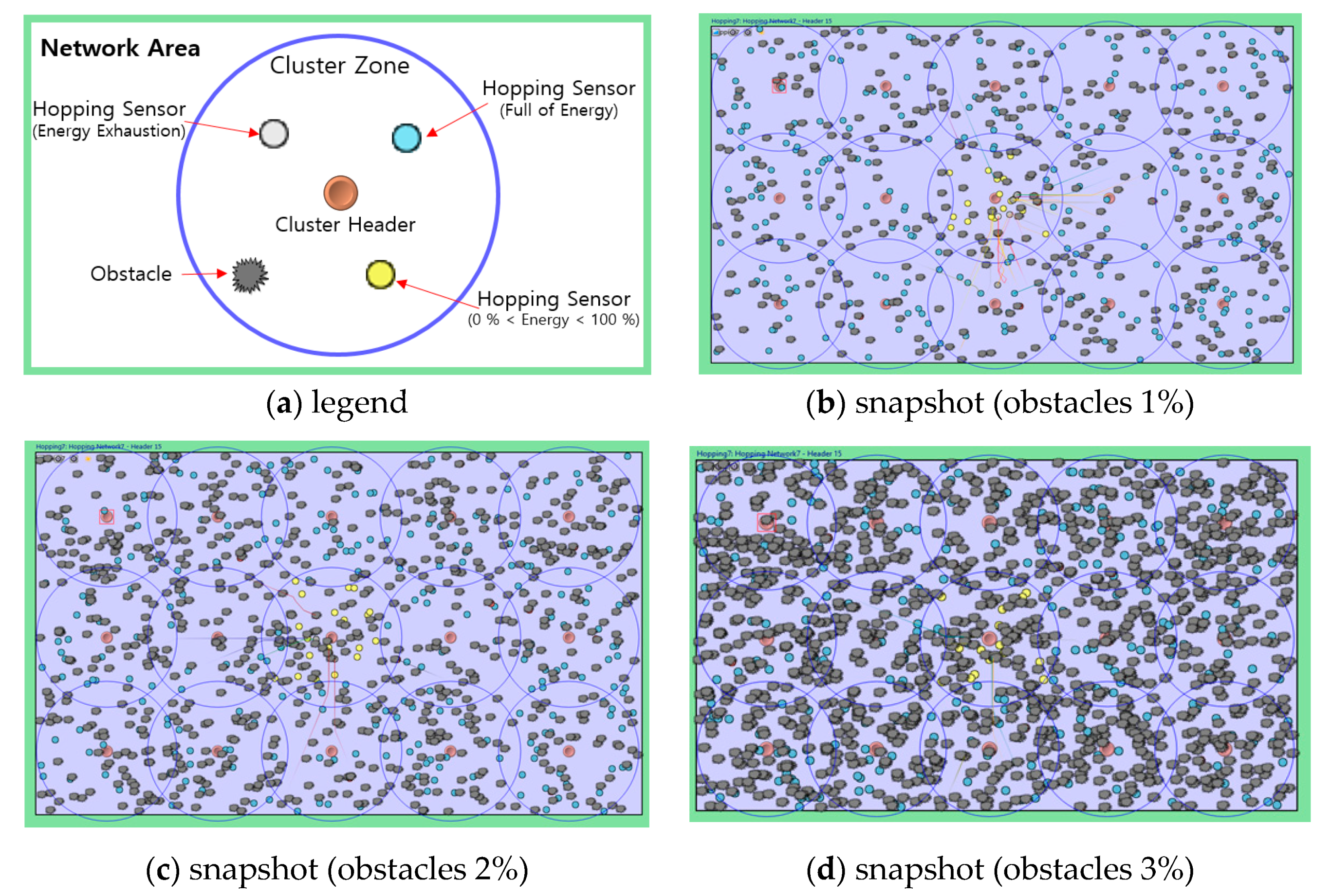
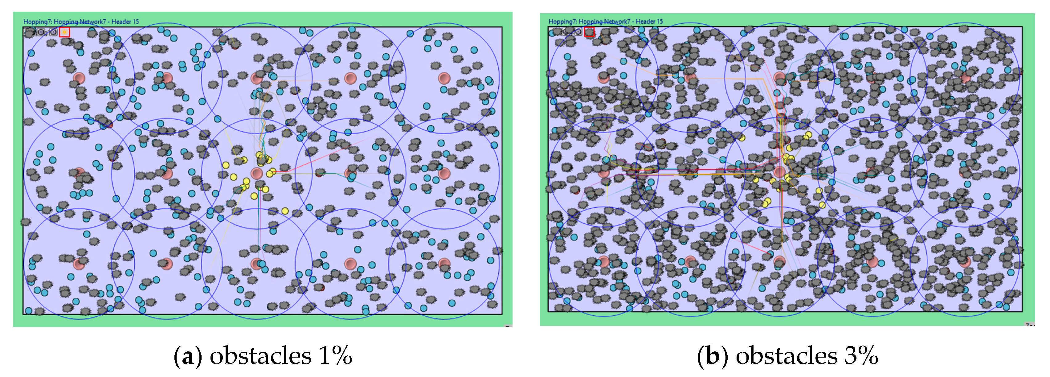
4. Simulation Results and Analysis

Unlike hopping sensor relocation studies so far, one of the most significant contributions this paper is the use of OMNeT++ [26], which can realistically reflect wireless communications situations in real-world environments. Table 1 describes the environment parameters used in the simulation for performance evaluation.
As shown in Figure 7, 285 hopping sensors are randomly scattered to the whole area of 250 m × 150 m to collect data. As mentioned in the previous Sections, since the aim of our research is not clustering techniques, we assume that the 15 cluster zones and headers are properly pre-set up in well-known ways. If there are fewer than 10 member sensor nodes in each cluster zone, excluding the cluster headers, the cluster header determines that its zone is a sensing hole.
As shown in Figure 7, obstacles are randomly generated with values of 1%, 2%, and 3% over the entire area. Although the size of the obstacle is very large in Figure 7d, the obstacle is actually 1 m × 1 m. Only for visual effects, we make the obstacle appear to be large. A communication model between sensors is used, IEEE 802.11, and the regular transmission radius is assumed to be 20 m. More specifically, antennaType, transmitterType, and receiverType parameters are set as IdealRadioMedium module environment in OMNeT++ [27]. While jumping as high as possible, each hopping sensor has a maximum radius of 29 m of transmission. It also can move forward 2 m with one jump.
In order to reflect the effect of the realistic environment (wind, etc.), the movement model of each hopping sensor node is assumed with two-dimensional standard normal distribution, where standard deviations are 0.3 and the correlation is zero, as shown in Figure 1. The movement of the hopping sensor is indicated by a solid line as shown in Figure 7. For the performance analysis of the proposed relocation protocol, the sensing hole occurred in the middle of area, as shown in Figure 7.
We assume the scenario that the sensor nodes continuously gather data in the middle cluster zone, and they consume energy rapidly. Each sensor in the middle cluster generates a data collection event with an exponential distribution (average of 5 min). For convenience, the initial energy value for sensing is set to 100, and the energy consumption is 1 for each event occurred. Any energy model can be adopted, but a specific energy model is not considered here for simplicity. The main flow of the paper is about the creation and restoration of the sensing hole. An occurrence of a sensing hole (less than 10 member sensor nodes) is determined by a cluster header after HELLO message for every 15-minute interval. In particular, to perform the simulation on relocation of member sensor nodes to recover the sensing hole occurred, sensor nodes in other zones are assumed to perform no data collection. It also indicates in yellow that a sensor has become faulted due to energy depletion after continuous data collection in Figure 7.
In the majority of the hopping sensor relocation protocols so far, each sensor node knows all network information; like a central-based relocation protocol, it only considers the shortest path between cluster zones. However, it is very difficult to implement in reality; therefore, we propose a distributed-based relocation protocol, in order to overcome the drawbacks of the previous central-based relocation protocols. The implementation of the proposed protocol and simulation for performance evaluation are based on OMNeT++, which takes all communication system layers into account and also reflects both distributed computing of all sensors and actual environments. As far as we know, our implementation of hopping movement model considering obstacles is the first attempt in this field of study.
As previously explained, a sensing event occurs only in the middle cluster zone. After a three-day-long simulation, the result is shown in Figure 8. The dead member sensor node is colored yellow and the path of each hopping sensor is plotted by a solid line. Also, the movement of the sensor is shown as a zigzag due to environmental factors such as wind. It can also be confirmed that sensors captured in obstacles can no longer move and become faulted.
We have simulated the relocation protocols using a sensor network topology generated randomly, and the results are described in Figure 9 and Figure 10. First, Figure 9 shows the sensor retention rate in the middle cluster. Since the minimum number of members for each cluster to properly gather data is 10, the sensor retention rate is 1 if there are more than 10 member sensor nodes. For example, if there are five sensor nodes, the sensor retention rate is 0.5 (= 5/10), and if there is only one sensor, the sensor retention rate is 0.1. Since the previous hopping sensor relocation protocol [19] ignores the existence of obstacles, the sensor retention rate of it tends to be much lower than that of the proposed protocol, as shown in Figure 9. Figure 9 shows the change of each sensor retention rate during about three days. Since the sensing hole of the middle cluster occurs continuously, the neighbors’ cluster headers might provide redundant sensors to recover the middle cluster’s sensing hole until around 1000 min. However, neighbors’ nodes are also depleted at that moment, thus the sensor retention rates in both schemes start to drop as shown in the green circle of Figure 9a. The blue circle of Figure 9a indicates that the proposed method considering obstacles shows better retention rate than previous scheme.
Figure 9b illustrates the difference between the sensor retention rates of the proposed and the previous protocols. It is easy to see that the number of top marks is more than that of below marks in Figure 9b. Since the sensor retention rates are only considered in the middle cluster zone, the denominator is ten, which is the minimum number of sensors to recover a sensing hole. In other words, if the difference of the rates is the positive 0.5, the proposed method accommodates five more sensors than the previous method at the same instance. A higher retention rate would result in requesting a smaller number of sensors compared with another method and generating fewer messages for movements to neighboring cluster zones. Hence, the proposed scheme would consume smaller energy to generate messages compared to the previous scheme and can play a major role in extending the lifetime of the network.
Specially, in Figure 9d of obstacles 3%, our protocol successfully recovers the sensing hole better than that of the previous one. In other words, it is possible to strongly predict that data collection could be better than the compared protocol, even if the cluster zone still cannot recover the sensing hole.
In the simulation, every HELLO message is periodically broadcasted by each cluster header. The interval is set to be 15 min, and the cluster header should determine whether or not its zone is a sensing hole for every interval time. Whenever each cluster header checks the state of the sensing hole and sends REQ message, the moments for sensing hole appearance are shown in Figure 10. The delayed occurrence of sensing holes of this protocol compared to previous one indicates that more successful data collection is achieved. In addition, as we mentioned earlier in the message flows, the short duration of each occurrence of the sensing hole means that numerous messages are generated for REQ throughout the entire network. This could lead to unnecessary energy consumption due to message storms. Furthermore, in order to successfully accomplish the continuous desired data correction at the end of the wireless sensor network (i.e., the sink nodes), a relocation protocol has to avoid unnecessary energy consumption. Therefore, our relocation protocol is appropriate to reduce unnecessary energy consumption.

5. Conclusions

In the wireless sensor network, hundreds of sensors are dispatched in the desired area and sensors are continuously operating. Various previous studies were conducted, including the proper placement of sensors and the selection of cluster headers to transmit the collected data to the desired sink nodes. However, wireless sensors are inherently energy-limited, thus the appearance of the sensing hole cannot be avoidable and sensing hole recovery to maintain network operation is necessary. In particular, since the charging system of the sensor is not always available, it is essential to consider energy-efficiency from the time the sensor is relocated to recover the sensing hole.
While there has been vigorous study of hopping mobility models suitable for rough areas recently, the majority of past studies have been based on not practical classic theory (i.e., relocation schemes based on source-based routing). In this paper, overcoming these problems, a new hopping sensor relocation protocol is proposed to suit the real distributed environment. To reflect the real situations, obstacles of a given area (stones, mud, etc.) have been considered. Since the status of obstacles around the sensing hole is unknown, the condition of the surrounding environment is predicted through the success rate of the hopping sensor relocation.
We would strongly emphasize that the relocation protocol proposed by this research team is a protocol in a distributed environment and the successful implementation of OMNeT++ simulation in the hopping sensor relocation protocol is our unique skill in this field of research. Various obstacles were considered for performance evaluation and analysis. Finally, superior energy efficiency with delaying sensing hole appearance of the proposed scheme was demonstrated.

Author Contributions

S.P. and M.K. are the co-first authors and contributed equally. S.P., M.K., and W.L. designed the protocol and the simulation process. S.P., M.K., and W.L. coordinated the grant funding, conducted the study, analyzed the data, and drafted the first version of the manuscript. The simulation was conducted by S.P. and M.K., and W.L. supervised the software development. All authors have read and agreed to the published version of the manuscript.

Funding

This work was supported by Research Assistance Program (2019) in the Incheon National University and the National Research Foundation of Korea (NRF) grant funded by the Ministry of Science, ICT & Future Planning (No. NRF - 2019R1G1A1007832).

Conflicts of Interest

The authors declare no conflict of interest.

References

  1. Yu, S.; Liu, M.; Dou, W.; Liu, X.; Zhou, S. Networking for Big Data: A Survey. IEEE Commun. Surv. Tutor. 2017, 19, 531–549. [Google Scholar] [CrossRef]
  2. Chen, M.; Mao, S.; Liu, Y. Big Data: A Survey. Mob. Netw. Appl. 2014, 19, 171–209. [Google Scholar] [CrossRef]
  3. Yaqoob, I.; Ahmed, E.; Hashem, I.A.T.; Ahmed, A.I.A.; Gani, A.; Imran, M.; Guizani, M. Internet of Things Architecture: Recent Advances, Taxonomy, Requirements, and Open Challenges. IEEE Wirel. Commun. 2017, 24, 10–16. [Google Scholar] [CrossRef]
  4. Zhang, Y.; Xiong, Z.; Niyato, D.; Wang, P.; Kim, D.I. Toward a Perpetual IoT System: Wireless Power Management Policy With Threshold Structure. IEEE Internet Things J. 2018, 5, 5254–5270. [Google Scholar] [CrossRef]
  5. Ray, P.P.; Mukherjee, M.; Shu, L. Internet of Things for Disaster Management: State-of-the-Art and Prospects. IEEE Access 2017, 5, 18818–18835. [Google Scholar] [CrossRef] [Green Version]
  6. Chudzikiewicz, J.; Furtak, J.; Zielinski, Z. Fault-tolerant techniques for the Internet of Military Things. In Proceedings of the IEEE 2nd World Forum on Internet of Things (WF-IoT), Milan, Italy, 14–16 December 2015; pp. 496–501. [Google Scholar]
  7. Kosar, R.; Onur, E.; Ersoy, C. Redeployment Based Sensing Hole Mitigation in Wireless Sensor Networks. In Proceedings of the IEEE 2009 Wireless Communications and Networking Conference (WCNC), Budapest, Hungary, 5–8 April 2009. [Google Scholar]
  8. Kim, M.; Park, S.; Lee, W. A Robust Energy Saving Data Dissemination Protocol for IoT-WSNs. In KSII Transactions on Internet and Information Systems (TIIS); 2018; pp. 5744–5764. [Google Scholar] [CrossRef]
  9. Kim, M.; Jeong, E.; Bang, Y.-C.; Hwang, S.; Shin, C.; Jin, G.-J.; Kim, B. An Energy-aware Multipath Routing Algorithm in Wireless Sensor Networks. IEICE Trans. Inf. Syst. 2008, 91, 2419–2427. [Google Scholar] [CrossRef] [Green Version]
  10. Elappila, M.; Chinara, S.; Parhi, D.R. Survivable Path Routing in WSN for IoT applications. Pervasive Mob. Comput. 2018, 43, 49–63. [Google Scholar] [CrossRef]
  11. Luo, R.C.; Huang, J.-T.; Chen, O. A Triangular Selection Path Planning Method with Dead Reckoning System for Wireless Mobile Sensor Mote. In Proceedings of the 2006 IEEE International Conference on Systems, Man and Cybernetics, Taipei, Taiwan, 8–11 October 2006; pp. 162–168. [Google Scholar]
  12. Chellappan, S.; Snyder, M.E.; Thakur, M. Distributed exploratory coverage with limited mobility. Int. J. Space-Based Situated Comput. 2014, 4, 114–124. [Google Scholar] [CrossRef]
  13. Snyder, M.E. Foundations of Coverage Algorithms in Autonomic Mobile Sensor Networks. Ph.D. Thesis, Missouri University of Science and Technology, Rolla, MO, USA, 2014. [Google Scholar]
  14. Zhao, J.; Xu, J.; Gao, B.; Xi, N.; Cintrón, F.J.; Mutka, M.W.; Xiao, L. MSU Jumper: A Single-Motor-Actuated Miniature Steerable Jumping Robot. IEEE Trans. Robot. 2013, 29, 602–614. [Google Scholar] [CrossRef]
  15. Cen, Z.; Mutka, M.W. Relocation of Hopping Sensors. In Proceedings of the IEEE International Conference on Robotics and Automation (ICRA 08), Pasadena, CA, USA, 19–23 May 2008; pp. 569–574. [Google Scholar]
  16. Kim, M.; Mutka, M.W. On Relocation of Hopping Sensors for Balanced Migration Distribution of Sensors; Springer: Berlin, Heidelberg, 2009; pp. 361–371. [Google Scholar]
  17. Kim, M.; Mutka, M.W. Multipath-based Relocation Schemes Considering Balanced Assignment for Hopping Sensors. In Proceedings of the IEEE/RSJ International Conference on Intelligent Robots and Systems (IROS 09), St. Louis, MO, USA, 10–15 October 2009; pp. 5095–5100. [Google Scholar]
  18. Kim, M.; Mutka, M.W.; Choo, H. On Relocation of Hopping Sensors for Rugged Terrains. In Proceedings of the IEEE International Conference on Computational Sciences and its Applications (ICCSA 10), Fukuoka, Japan, 23–26 March 2010; pp. 203–210. [Google Scholar]
  19. Kim, M.; Park, S.; Lee, W. Energy and Distance-Aware Hopping Sensor Relocation for Wireless Sensor Networks. Sensors 2019, 19, 1567. [Google Scholar] [CrossRef] [PubMed] [Green Version]
  20. OMNeT Web Site. Available online: https://www.omnetpp.org (accessed on 9 December 2019).
  21. Cintr’on, F.; Pongaliur, K.; Mutka, M.W.; Xiao, L.; Zhao, J.; Xi, N. Leveraging height in a jumping sensor network to extend network coverage. IEEE Trans. Wirel. Commun. 2012, 11, 1840–1849. [Google Scholar] [CrossRef]
  22. Cintr’on, F. Network Issues for 3D Wireless Sensors Networks. Ph.D. Thesis, Michigan State University, East Lansing, MI, USA, 2013. [Google Scholar]
  23. Kim, M.; Kim, T.; Shon, M.; Kim, M.; Choo, H. Design of a Transmission Process for Hopping Sensors to Enhance Coverage. In Proceedings of the International Conference Wireless Networks (ICWN 10), Las Vegas, NV, USA, 12–15 July 2010; pp. 377–382. [Google Scholar]
  24. Rostami, A.S.; Badkoobe, M.; Mohanna, F.; Keshavarz, H.; Hosseinabadi, A.A.R.; Sangaiah, A.K. Survey on clustering in heterogeneous and homogeneous wireless sensor networks. J. Supercomput. 2018, 74, 277–323. [Google Scholar] [CrossRef]
  25. Sabor, N.; Sasaki, S.; Abo-Zahhad, M.; Ahmed, S.M. A Comprehensive Survey on Hierarchical-Based Routing Protocols for Mobile Wireless Sensor Networks: Review, Taxonomy, and Future Directions, Hindawi. Wirel. Commun. Mob. Comput. 2017, 2017, 23. [Google Scholar] [CrossRef]
  26. Zarrad, A.; Alsmadi, I. Evaluating network test scenarios for network simulators systems. International J. Distrib. Sens. Netw. 2017, 13, 1550147717738216. [Google Scholar] [CrossRef]
  27. Virdis, A.; Kirsche, M. Recent Advances in Network Simulation: The OMNeT++ Environment and Its Ecosystem; Springer: Cham, Switzerland, 2019. [Google Scholar] [CrossRef]
Figure 1. An example of the movement of a hopping sensor considering movement-error.
Electronics 09 00049 g001
Figure 2. The defined terms for hopping sensor network.
Electronics 09 00049 g002
Figure 3. An example of recovering a sensing hole with cross-clusters.
Electronics 09 00049 g003
Figure 4. Scenario and message flow diagram for describing the proposed protocol.
Electronics 09 00049 g004
Figure 5. Examples of comparison between the previous and proposed relocations.
Electronics 09 00049 g005
Figure 6. Message flows for two scenarios.
Electronics 09 00049 g006
Figure 7. Simulation snapshots for each environment.
Electronics 09 00049 g007
Figure 8. Simulation snapshots finished for each obstacle.
Electronics 09 00049 g008
Figure 9. Sensor retention rates at the middle cluster.
Electronics 09 00049 g009
Figure 10. The moments for sensing hole appearance at the middle cluster zone.
Electronics 09 00049 g010
Table 1. Simulation environments.
network area250 m × 150 m
number of all member hopping sensor nodes285
number of cluster headers15
minimum number of members for each cluster to properly gather data
(i.e., a sensing hole occurs if number of current members lower than the value)
10
the probability that an obstacle exists0%, 1%, 2%, 3%
maximum communication radius for each sensor node20 m
maximum communication radius when highly jumping29 m
maximum distance that a sensor node moves forward with one jump2 m

