1. Introduction
During the past three decades, the telecommunication industry has faced an impressive growth not only in the number of subscribers worldwide, but also in the demand for higher-speed data transmissions [
1]. To this end, orthogonal frequency division multiplexing (OFDM)-based radio-over-fiber (RoF) technology, combining the benefits of optical fiber and millimeter-wave wireless links, has been proven as the solution to support secure, cost-effective, and high-capacity vehicular/mobile/wireless access for the topic generation communication systems [
2]. There are two types of receiver used in the implementation of RoF-OFDM systems: direct detection [
3] and coherent detection [
4]. Direct detection is characterized by a simple and economical base station, but with the cost of a worse receiving sensitivity when contrasted with coherent detection. Currently, direct detection is massively adopted because it allows using low-priced distributed feedback (DFB) lasers [
5]. The reason behind DFB adoption is owed to the optical carrier and the single-sideband OFDM signal coming from the same optical source, namely the field experiment phase coherency at the central station. Nevertheless, the chromatic fiber dispersion progressively phase decorrelates optical signals as the transmission distance from the central station to a base station increases, originating phase noise at the photo-detected current. In RoF-OFDM systems, the communication from the base stations to the mobile terminals is through millimeter waves, where the system performance impairment due to phase noise is particularly detrimental [
6]. In these schemes with a narrow bandwidth of the signal and a high millimeter wave, phase error leads to inter-carrier interference (ICI) and a rotation of each subcarrier, termed common phase error (CPE) [
7]. By maintaining an effective information rate, as well as the simplicity of the digital signal processing, the pilot-assisted channel-correction method can efficiently correct the phase noise variations for small OFDM symbol periods [
8]. This equalizer is included in most OFDM modems with the purpose of correcting the wireless channel. The complex interrelation between the chromatic dispersion effect and the feasible pilot-based equalization has been recently studied in [
9], finding three different regimes as the combined tones become phase-decorrelated. The first and the second zones correspond for to case of partially phase-correlated fields. Meanwhile, the third regime occurs when there is no phase coherency between the tones. The phase noise compensator is only useful in the first zone (the OFDM symbol period does not exceed the time delay parameter that quantifies the chromatic dispersion effect). All these results are explained via a novel phase noise metric for multicarrier signals in the partial phase-decorrelation scenario, which counts the effectiveness of the equalizer.
Recently, extreme learning machines (ELMs) have been reported as a promising learning algorithm for single-hidden layer feedforward neural networks (SLFNs) [
10]. The weights of the input layer and the biases in the hidden layer are arbitrarily originated and, then, the weights of the output layer are analytically obtained by solving an overdetermined linear system through the Moore–Penrose pseudo-inverse [
11]. Results based on real-world benchmarking function approximation and classification problems have shown that contrasted with the popular back-propagation algorithm and the support vector machines for SLFNs, the ELM algorithm is extremely simple, runs extraordinarily rapidly, and tends to provide better generalization performances [
10,
12,
13,
14,
15]. With the fast development of artificial intelligence, extreme learning machines have been recently employed in communication systems for equalization purposes. For quadrature phase shift keying (QPSK) signaling, the superiority of the complex ELM over the complex minimal resource allocation network, complex radial basis function network, and complex back-propagation equalizers in terms of the symbol error rate and the learning speed is revealed, where a complex non-minimum-phase channel model channel of order three is taken into account [
12]. In an additive white Gaussian noise (AWGN) channel, the standard ELM algorithm is utilized as a novel classification framework to perform correct symbol detection for amplitude phase shift keying constellations [
16] by showing the same symbol and bit error rates as the well-known max log maximum a posteriori method (the optimal solution for symbol detection in single carrier). For OFDM signals over a frequency selective fading channel subject to diverse values of the signal-to-noise ratio (SNR), an algorithm that employs real-valued ELM that jointly solves the issue of equalization and symbol detection for QPSK and 16 quadrature amplitude modulation (16-QAM) formats is presented [
17]. Simulation results show that the proposed technique outperforms other learning-based equalizers in terms of the symbol error rate and the training speed. These results are obtained in the following situation: data subcarriers are split into training and testing data by decreasing the overall throughput; pilot symbols that always exist in the OFDM signals are not exploited. For coherent optical OFDM, the performance analysis of Wilcoxon-based machine learning nonlinear equalizers is exposed [
18], by reporting that the nonlinear equalizers trained with Wilcoxon multilayer perceptron, Wilcoxon generalized radial basis function, and Wilcoxon robust ELM give enhanced performance in terms of the Q-factor as compared to non-robust algorithms (based on minimization of the least squares error principle). Here, the algorithm based on the ELM converges faster than the other algorithms.
In our work, phase noise estimation methods based on ELMs in the real and complex domains are presented in the context of direct-detection RoF-OFDM signals with QPSK as the subcarrier modulation format. The SLFN for the fully-complex ELM has a single input and output to reinforce the learning stage; the method only trains the pilot subcarriers to make the output of the network converge extremely fast, and phase and amplitude noises in the data symbols are simply compensated by multiplexing the output weight vector obtained from pilots and the hidden layer output matrix of the data subcarriers. For the real ELM algorithm, the complex OFDM signal is divided into its real and imaginary components and then fed into two different real-valued ELMs. The main contributions of the manuscript can be summarized as follows: (1) The ELM algorithms in the real and complex domains for phase noise estimation are introduced for the first time, by exploiting the pilots to achieve a real-time learning stage, as well as to maintain the spectral efficiency. (2) In terms of the bit error rate (BER), as well as the time simplicity, the superiority of the fully-complex ELM among the feasible pilot-assisted equalization and the real ELM is revealed for numerous laser linewidths, SNRs, transmission distances, radio frequencies, and OFDM symbol periods. Furthermore, the complex ELM almost achieves the same BER as the CPE compensation, which decreases the transmission rate. (3) For a certain relationship between the laser phase noise and the duration of a single OFDM symbol, any phase noise compensation may reduce the BER more for a narrow laser linewidth or a long OFDM symbol period, as long as there is partial phase-decorrelation between the combined fields. Therefore, by using the complex ELM with the assistance of pilot subcarriers at the training phase, better and faster OFDM modems could be designed and implemented for the topic and future communication systems.
The rest of the paper is organized as follows.
Section 2 presents the transmitted and received signals of the RoF-OFDM scheme subject to a direct detection approach.
Section 3 mathematically details the complex ELM algorithm. In
Section 4, the phase noise suppression techniques based on ELMs in the real and complex planes are introduced.
Section 5 shows the system performance as a function of the decorrelation degree between the fields after the photo detection process, which is discussed in
Section 6 taking into account the overall practical design purposes. Finally,
Section 7 gives concluding remarks.
2. Orthogonal Frequency Division Multiplexing Radio over Fiber Systems
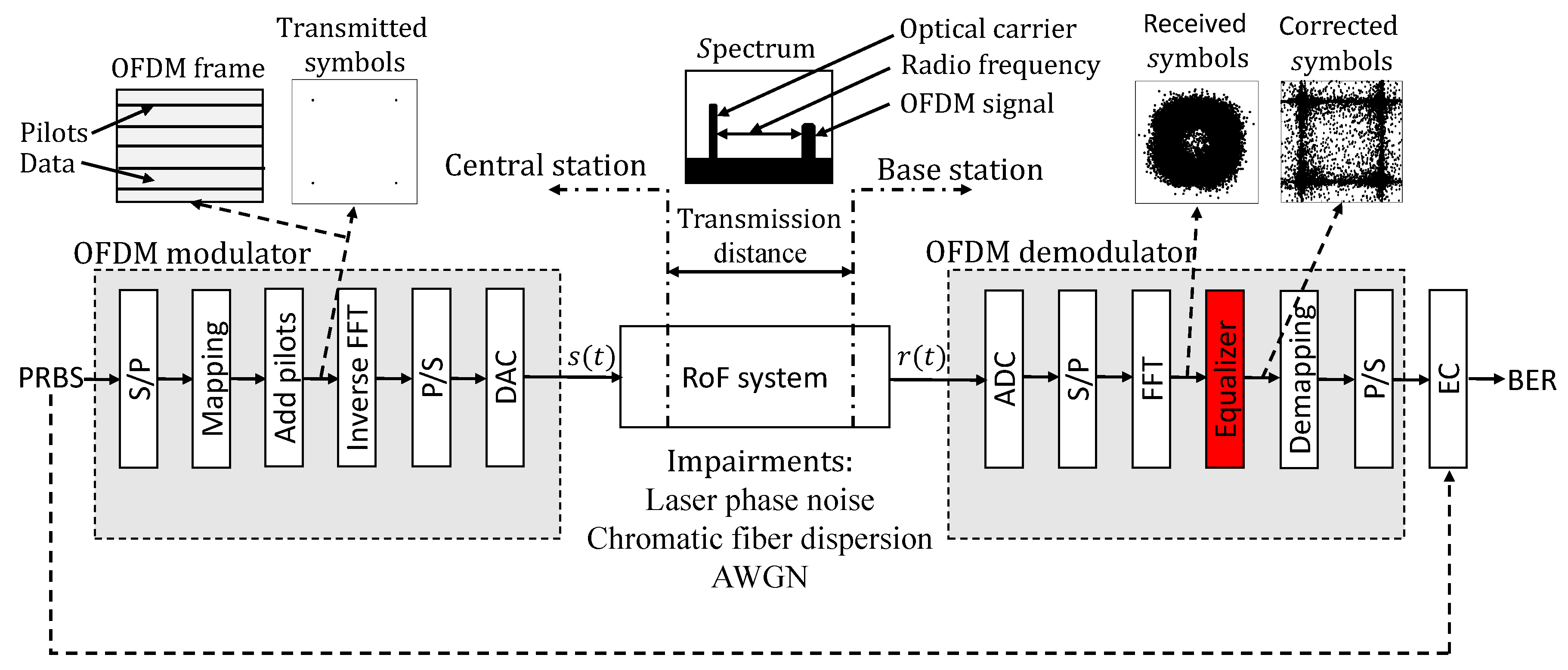
To begin, the block diagram of the direct-detection RoF system focused on the OFDM modem and the simulation parameters is displayed in
Figure 1. A single baseband OFDM symbol with a symbol duration of
is given by [
19]:
with
N and
being the number of subcarriers and the symbol constellations, respectively. The number of subcarriers comes from the summation of the number of pilot and data signals (
). Depending on the subcarrier position, a symbol constellation takes the value of either the data symbol
or the pilot symbol
[
20]. If the OFDM-based RoF system is characterized by correlated-phase fields at the central station (the direct optical detection approach), the input to the OFDM demodulator is corrupted by (i) phase noise due to laser linewidth, as well as chromatic dispersion [
9] and (ii) AWGN due to thermal and shot noises [
21]. After the photo detection and down-conversion processes, the RoF-OFDM signal may be written as [
22]:
where
denotes the phase rotation as a consequence of the time delay parameter
and
and
are the radio frequency and the optical carrier, respectively. It is worth mentioning that
models the chromatic fiber dispersion effect as long as the OFDM bandwidth is much smaller than the radio frequency [
7] and can be interpreted as the phase-decorrelation degree between the mixed tones in the photo detection process [
9].
refers to the differential phase noise, where
is phase noise modeled from a Wiener process quantified by the laser linewidth
. Note that all stages experimenting with the RoF-OFDM signal from the central station to a certain base station were explained in our previous work [
9]. The authors in [
23] revealed that in terms of the time delay parameter, the heterodyning field correlates perfectly (
), decorrelates partially (
), or decorrelates completely (
). AWGN is represented by
, which is the complex base-band signal. In order to focus on the impact of phase noise in the system performance, Expression (2) makes sense for the case of linear field modulation without the presence of the optical carrier at the intermediate frequency.
In the demodulation step, each OFDM symbol is sampled at the sampling rate in order to mimic an analog-to-digital converter (ADC), convert into
N parallel data pipes (the serial-to-parallel process (S/P)), and demodulated via the fast Fourier transform (FFT) module, whose size is also given by
N (i.e., DC subcarrier and null data are not considered for the sake of simplicity). Therefore, the
symbol constellation (a single QPSK symbol during the OFDM symbol period) acquires the form of [
19]:
where
refers to the discrete-time converted phase fluctuation,
represents the AWGN at the
subcarrier, and
, i.e., is the FFT of
. It is noted that (i) the received k
th symbol constellation shows a rotation by the first term (CPE), as well as a dispersion by the second term (ICI), and the last term (AWGN) and (ii) all subcarriers are closely related. Taking into account the latter observation and the representation of the data and pilot symbols, the following matrix may denote an OFDM symbol before the equalization stage:
As seen, pilots are uniformly added in the OFDM frame, and by linear interpolation of these in the frequency domain, the distortion in data symbols caused by phase noise may effectively be reduced for time delays less than the OFDM symbol period [
9]. In [
20], the linear interpolation has shown acceptable performance together with a simple realization. Notice that this compensation results from the pilot-based equalization technique required for correcting the multipath channel effects in millimeter frequencies from a certain base station to the numerous mobile terminals in RoF-OFDM schemes [
24], first demonstrated in [
8].
3. Complex Extreme Learning Machine
Given a training set with
L samples (
), where
(
n is the size of the inputs) and
(
m is the size of the outputs), the actual outputs of the SLFN with
hidden neurons are mathematically modeled as [
12]:
where
refers to the output weight vector between the
hidden neuron and the output neurons,
denotes the activation function that must be bounded and differentiable almost everywhere in the complex domain,
represents the input weight vector connecting the input nodes and the
hidden node, the term
means the inner product of the column vectors
and
, and
is the bias of the
hidden neuron. Both the input weights and hidden layer biases are randomly assigned based on any continuous distribution probability inside the radius of the converge of the mapping function. Equation (
5) may compactly be written as:
H is called the hidden layer output matrix of the ELM; its
column results from the
hidden node’s output vector with respect to
inputs. Its smallest norm least-squares solution is given by [
10]:
where
refers to the Moore–Penrose generalized inverse of the hidden layer output matrix, which can be solved by various methods, such as orthogonal projection, the Gaussian method, the iterative method, singular value decomposition, among others [
11]. In the paper, this inverse matrix is found though the singular value decomposition approach in order to avoid time limitations and matrix requirements [
10]. As can be seen, a standard SLFN subject to the ELM algorithm possesses the following benefits: high accuracy, least user intervention, and real-time learning. The overall ELM architecture is depicted in
Figure 2, where all inputs, variables, and outputs are identified. In the next section, we explain how this artificial neural network can act as the equalizer in the OFDM receiver. Taking into account that the complex ELM comes from a direct extension from the real ELM to the complex plane [
12,
14], the presentation of the fully-real ELM is discarded in the manuscript.
4. Proposed Phase Noise Suppression Methods through Extreme Learning Machines
In this section, we introduce the real and complex ELMs to diminish phase and amplitude noises in OFDM-based RoF systems following the OFDM frame used by the default pilot-assisted channel correction (see
Figure 1). In other words, both novel methods are distinguished by no additional overhead and/or no modification of the transmitter and receiver of an overall OFDM scheme. For the proposed methods, pilots must be modulated by the desired constellation points in order to get successful learning in the artificial neural network and, thus, track the phase noise variations in each constellation symbol. The minimum number of pilots is therefore given by the M-ary subcarrier modulation format; 64 pilot subcarriers for a 64QAM-OFDM signal, for instance. If the subcarriers are modulated with high spectral efficiency formats, the required pilots for these novel phase error correction methods would become the main disadvantage owing to transmission efficiency reasons. In this scenario, the pilot-based equalization technique could be adopted. The fully-complex ELM possesses a single input and a single output to reinforce the training stage, where the training and the input testing parts are pilot and data subcarriers, respectively, during each OFDM symbol period. Remembering the previous section, the learning stage is hence formed by the following steps: (i) arbitrarily assign the input weights
and the biases of the hidden nodes
; (ii) given the activation function
and the hidden neuron number
, calculate the Moore–Penrose generalized inverse of the hidden layer output matrix
H; and (iii) according to Formula (7), solve the output weight
. In other words, the learning phase by using the information given by the pilot subcarriers can be summarized as:
where the samples
L matches the number of pilots
and
and
P depend on the received
and transmitted
reference symbols, respectively. In order to diminish the phase noise effects in the received OFDM signal, the test performance of the ELM algorithm is finally carried out:
where the output matrix
D contains the corrected data symbols
, the number of samples is equal to the number of data subcarriers (
), and the hidden layer output matrix
H is a function of the received data symbols without equalization
. As a pilot-assisted equalization method, all this procedure is done OFDM symbol-by-OFDM symbol in order to follow the rapid variations in the time and frequency domains, which come from the optical and/or wireless channels. Evidently, as the training samples (the number of pilots) increases, the success rate in the testing stage increases, i.e., the BER improves. However, the relationship between the number of data subcarriers and pilot subcarriers is about 10:1 for spectral efficiency purposes [
20]. For the real ELM, the complex signal is divided into two inputs (one for the real number and one for the imaginary part), fed into different real-valued ELMs, and joined in the Cartesian form for recovering the corrected data subcarrier. The ELM phase noise suppression pseudo-codes can be summarized as:
| Algorithm 1: The complex ELM |
Input:
The training test (the pilots subcarriers) .
The complex activation function .
The number of hidden nodes
Output:
The corrected data symbols }.
- 1
Assign arbitrarily the complex input weights and the complex biases . - 2
Calculate the Moore–Penrose generalized inverse of the hidden layer output matrix ( from the received pilot subcarriers (). - 3
Determine the output weight by the product of the matrix and the transmitted pilot subcarriers (), Equation (8). The learning procedure is finished. - 4
Obtain the hidden layer output matrix (H) from the received data symbols (). - 5
Find the corrected data symbols () through the relationship between H and , Formula (9). The testing step is done.
|
| Algorithm 2: The real ELM |
 |
Equation (
9) and Algorithms 1 and 2 demonstrate that in a simple and efficient way, the introduced ELM approaches may reduce phase noise and AWGN effects in a typical pilot-based RoF-OFDM signal.
5. Results
As mentioned, the RoF-OFDM schemes with direct detection allow the use of commercial cost-effective DFB lasers and offer the advantage of compact and simple receivers. Unfortunately, as the fiber length between the central station and the base station increases, the transmitted tones (the optical carrier and the sideband OFDM signal) lose their phase coherency; inducing important phase noise in the photo-generated current. This phenomenon comes from the chromatic fiber dispersion, which may be modeled via the time delay parameter as follows [
22]:
where
D is the dispersion parameter,
L denotes the transmission distance,
c represents the light speed in vacuum, and
refers to the operating frequency. The expression (10) makes sense in the situation of narrow OFDM signals and high radio frequencies [
7].
In order to not restrict the observations to some value of the millimeter frequency given a certain fiber length or vice versa (see Expression (10)), we initially studied the OFDM tolerance to laser phase noise and AWGN as the time delay increases in RoF systems with the assistance of real and complex ELMs in the demodulation stage. To this end,
Table 1 illustrates the simulation parameters used, which were based on a recent work [
6] that took into account typical RoF-OFDM signals [
6,
9,
22,
25]. The considered laser linewidths were in the order of MHz to model low-priced DFB lasers [
5], by allowing reaching a BER threshold of
[
26] at certain time delays. The post forward error correction (FEC) BER could reach values in the order of
by utilizing modern FEC architectures [
27]; however, no channel coding was taken into account in the manuscript. The BER was estimated via Monte Carlo simulations with the direct error counting method, i.e., 10 runs of
bits were performed for having a confidence interval of 95% with an uncertainty factor of two on the error rate scale [
28]. On the other hand, following an easy methodology employed in [
26,
29], we realized the complexity evaluation of these new approaches by estimating the average elapsed time at the OFDM equalizer. In the next section, results are discussed and, consequently, exposed in terms of the relationship between the radio frequency and the distance from the central station to the base station.
We first determined the number of the hidden neurons and the mapping function of the ELMs that enhanced the BER, by setting the laser linewidth to 0.5 MHz and by discarding AWGN for the moment. As mentioned, this laser linewidth parameter can represent a typical DFB laser and was chosen in order to observe all the system performance evolution (from BER =
to BER =
) as the chromatic dispersion effect increases. On the one hand,
Figure 3 displays the BER in terms of the time delay parameter with the number of the hidden neurons as the parameter for (a) the real ELM with the sigmoid mapping function and (b) the complex ELM with the tanh mapping function. These activation functions were employed for demonstration purposes. The input weight vectors and biases of the fully-real and fully-complex ELMs were randomly chosen according to the uniform distribution on (−1,1) [
15] and from a complex area centered at the origin with the radius set as 0.005 [
13], respectively. For the real ELM (see
Figure 3a), the system performance deteriorated as the amount of phase correlation between the beating tones increased until these fields were completely decorrelated, where the BER reached its maximum value. From 10 hidden neurons to forward, the ELM effectively diminished phase error. With a single hidden neuron, the novel method was useless. Instead, for the complex ELM (see
Figure 3b), the BER depended on the decorrelation degree between the mixed fields in the following form: the BER rapidly and slowly augmented for time delays less and greater than the OFDM symbol period, respectively, and the system performance revealed its worst result when the combined tones completely lost the phase coherence. The proposed technique in the presence of two hidden neurons was highlighted in terms of phase noise correction. The reasons behind the different system performances of the real and complex ELMs may be explained via the effectiveness of the phase noise compensator (see the constellation histograms in
Figure 4) and the evolution of the ICI term (see the zoom of the power spectral densities of a demodulated OFDM signal in
Figure 5) in terms of the time delay parameter; but its detailed study is left for future analysis. On the other hand,
Figure 6 depicts the BER as a function of the time delay with the activation function as a parameter for (a) fully-real and (b) fully-complex ELMs in the presence of their best number of hidden neurons, previously found. The input weights and biases of the real ELM again obeyed a uniform distribution from −1–1, and those of the complex ELM were inside the radius of the converge of the complex mapping function used [
13]. For the real ELM (see
Figure 6a), sigmoid (SIG) and hyperbolic tangent (HT) functions outperformed the rest of the mapping functions: cosine (COS), hard limit (HL), triangular basis (TB), and radial basis (RB), by reducing the chromatic dispersion effect in the BER; the performance of the TB function was disastrous. For the complex ELM (see
Figure 6b), in the same context, the arcsin (AS), sinh (SH), tanh (TH), sin (S), and tan (T) functions were superior to the arcsinh (ASH), arctanh (ATH), and arctan (AT) functions. Note that according to the simulations, this optimization process led to the same number of hidden nodes and mapping functions for other laser phase noises and AWGN levels.
Afterward, we contrast in terms of improving the symbol constellation detection the introduced schemes with the feasible pilot-assisted equalization [
9] and without phase error mitigation as the BER limiting references. It is worth noting that this comparison was not carried out with pilot tone phase-noise suppression [
22] and post phase-noise suppression [
25] algorithms (the most famous compensators), since the former decreases the bit-rate efficiency, and the latter increases the digital-signal-processing complexity and cost. Instead, our proposals were highlighted by no additional overhead, as well as no modification of the standard OFDM signal; refer to
Section 4. Additionally, the complex ELM was better than the pilot-based channel correction in terms of the complexity evaluation, as seen below. In the scenario of a broad laser linewidth and/or a long fiber length, time delay pre-compensations between the central station and each base station [
30], self-homodyne RF receivers [
31], or phase-insensitive RF envelope detectors [
32] could be implemented to eliminate the impact of phase error in the system performance. These solutions massively increased the cost of the RoF network design. On the other hand, the CPE compensation [
33] may be useful for low phase errors prone to short OFDM symbol periods, but with the cost of needing an extra preamble in every OFDM frame for equalization purposes. Both BER upper bonds were also exposed for comparison purposes. Phase-insensitive results were analytically found [
34], while the BERs resulted from the CPE compensation were simulated. According to the previous performances, the real ELM composed of 10 hidden neurons prone to the sigmoid mapping function and the complex ELM together with two hidden neurons affected by the tanh activation function were adopted. For the case of not fighting phase error (the worst scenario), the results were theoretically obtained [
9]. Note that in terms of sensitivity, complexity, and capacity, a survey regarding phase noise reduction mechanism for optical OFDM communications is a research opportunity.
Firstly,
Figure 7 shows the BER as the heterodyning tones became decorrelated with the laser linewidth as the parameter and without AWGN. The superiority of the complex ELM among the pilot-assisted equalizer and the real ELM in terms of phase noise correction is clear, which is more notorious for narrow lasers. The advantage of the complex ELM over the real ELM can be attributed to only the former combining the quadrature and in-phase components at the learning step; contrast Algorithms 1 and 2. Notice that below the FEC threshold, the real ELM outperformed the pilot-based channel correction; otherwise, the opposite happened. With the benefit of an effective bit rate, the algorithm ELM in the complex domain almost obtained the same BER as the CPE compensation. As the laser linewidth increased, these system performances tended to match. The BER led to augmentation when phase noise was not combated, while in the presence of phase-insensitive methods, the BER acquired its best performance. Lastly,
Figure 8 displays the system performance as a function of the decorrelation degree between the mixed tones with the SNR as the parameter and a 0.5-MHz laser linewidth according to the different phase error compensation methods. In this scenario, all previous results occurred again with the following observations: (1) The complex ELM improvement increased as AWGN disappeared. By replacing the pilot-assisted equalization by the fully-complex ELM when the heterodyning fields were phase-uncorrelated (
), for demonstration purposes, the BER decreased from
to
with an SNR equal to 12 dB for the AWGN channel, while from
to
in the absence of AWGN (SNR = ∞dB). This BER improvement also happened for the different simulated SNR values, being more relevant for high SNRs as mentioned, and along the time delay axis. (2) As the SNR value increased and/or the time delay parameter decreased, the CPE compensation performed better than the ELM complex. (3) For high partially phase-correlated tones, the fact of reducing the phase noise helped to minimize the BER result of phase-insensitive methods owing to the phase-noise mitigation combating AWGN as well.
In
Table 2, we finally report the complexity of the new mechanisms with the pilot-assisted equalization technique by measuring the elapsed time (expressed in ms) at the equalization stage of the OFDM demodulator, where the design and implementation could change. As mentioned, this methodology was based on previous works due to simplicity [
26,
29]. The 95% confidence interval [
28] of this metric was obtained via
runs in the next computer system: Intel (R) Core (TM) i5 at 2.6 GHz with 4 GB RAM. On the one hand, the real ELM demanded more computational effort owing to it being composed of two different ELMs with 10 hidden nodes. On the other hand, as expected, the complex ELM formed by only two hidden neurons took the shortest evaluation time. Consequently, the complex ELM phase error reduction scheme was characterized by not only low complexity, but also high precision.
6. Discussion
It is well known that the most important measurement in the telecommunication industry is the BER vs. SNR curve. For this metric, results are now exposed and evaluated with the
relationship (i.e., the phase-decorrelation degree between the fields at the base station) as the parameter for overall design purposes. Novel methods and the pilot-based equalizer were only taken into account. In order to expand the observations for various RoF-OFDM signals, the next laser linewidths and OFDM symbol periods respectively were simulated: (a) 0.5 MHz and 32 ns, (b) 0.5 MHz and 64 ns, (c) 0.5 MHz and 128 ns, (d) 1 MHz and 32 ns, (e) 1 MHz and 64 ns, and (f) 1 MHz and 128 ns for
Figure 9 and (a) 5 MHz and 3.2 ns, (b) 5 MHz and 6.4 ns, (c) 5 MHz and 12.8 ns, (d) 10 MHz and 3.2 ns, (e) 10 MHz and 6.4 ns, and (f) 10 MHz and 12.8 ns for
Figure 10. Keeping in mind the values of the laser phase noise and the duration of a single OFDM symbol, three time delays were chosen to expose each of the system performances distinguished by the complex ELM (see
Section 5), as well as the pilot-based channel correction [
9]. As noted before, the BER minimized as the product between the fiber length and radio frequency decreased, the laser linewidth tended to 0 Hz, and/or the SNR increased. As the
parameter increased, the BER value subject to phase noise compensation did not change in terms of the laser linewidth times the OFDM symbol period (
). To the best of the authors’ knowledge, this behavior was exclusively noticed for phase-uncorrelated tones (where the system performance exclusively depended on the
relationship, instead of the laser linewidth and the OFDM symbol period independently) [
35,
36]. In the partial phase-decorrelation situation, however, it was revealed for the first time that given a certain
, the phase noise mitigation techniques were more beneficial as the laser phase noise diminished or the duration of an OFDM symbol augmented. The previous results can be seen via the contrast of
Figure 9b–e, whose
parameters were. The corresponding
Figure 10 exhibits the same observation. The reasons behind these results were beyond the purpose of the current investigation (the introduction of real and complex ELMs for diminishing phase noise in direct-detection OFDM-based RoF schemes, by exploiting the information in-phase and amplitude that provided the unmodulated subcarriers); nonetheless, they could be explained by calculating the residual phase error of a multicarrier signal characterized by partial phase-decorrelation. Note that without reducing phase noise, the system performance did not depend on the OFDM symbol period [
9]. Regarding the effectiveness of the phase error compensation mechanisms, the ELM algorithm in the complex domain was the best choice for all OFDM symbol periods, which was followed by the fully-real ELM in the situation of a 3.75 Gbps OFDM signal (see
Figure 9b,e) and as noticed in the preceding section. For OFDM symbol periods less than 64 ns, the pilot-assisted equalization outperformed the real ELM (see
Figure 9a,c and
Figure 10); otherwise, the opposite occurred as long as AWGN decreased (see
Figure 9d,f).
For the above phase error correction methods and an OFDM-based RoF signal of 64 ns,
Figure 11 exhibits finally the SNR and laser linewidth requirements at the FEC threshold with the
relationship as the parameter. These requirements decreased as the amount of phase-correlation between the beating tones diminished, being more relaxed via the fully-complex ELM. For instance, given a 60-GHz application along 1250 km that imposes 14-dB SNR, the laser linewidth can be extended from 0.48 MHz to 0.75 MHz, by replacing the default pilot-based channel correction by the ELM algorithm in the complex domain. Hence, the superiority of the complex ELM among the others of techniques in terms of fighting amplitude and phase noises was confirmed. This advantage was more relevant for long distances and/or high frequencies. For low laser linewidths and high SNRs, the system performance was limited by AWGN and the phase noise of the laser oscillator, respectively. For a product of the fiber length and radio frequency less than 750 km-GHz, the successful OFDM reception depended on the SNR value; the laser linewidth contribution was negligible. Instead, for time delays greater than the OFDM symbol period, the BER limit was unattainable even in the absence of AWGN; see
Figure 7. In the design of optical communication schemes, nevertheless, the maximum range was limited by the loss and nonlinearity of the fiber [
21], which should be taken into account for a complete analysis. Note that since the bandwidth of the transmitted OFDM signal corresponded to 2 GHz, the radio frequency for this result must be greater than or equal to 20 MHz to properly model the chromatic dispersion effect.
7. Conclusions
In our work, without increasing the OFDM modem complexity and decreasing the effective bit rate, we introduced novel phase noise mitigation techniques employing fully-real and fully-complex ELMs in order to reduce amplitude and phase noises effectively and, then, enhance the system performance significantly. In a standard SLFN composed by one input and one output and prone to the ELM algorithm, the training set corresponded to the pilots for diminishing the rotation and dispersion effects on data-carrying subcarriers (testing set). As the pilot subcarriers were exploited, the learning phase happened in real-time, and additionally, the general throughput was not decreased. According to BER minimization purposes, the number of hidden nodes and the activation function for each ELM were initially found. Afterward, the effectiveness of the ELM algorithm in the complex domain was demonstrated regarding the feasible pilot-assisted equalization and real ELM techniques for a QPSK-OFDM based RoF scheme taking into account the following parameters: fiber length, radio frequency, laser linewidth, SNR, and OFDM symbol period. For any duration of an OFDM symbol, this superiority increased as the chromatic dispersion effect increased, laser phase noise decreased, and AWGN disappeared, which made the cost of RoF-OFDM schemes lower by the use of noisier lasers, for instance. As the heterodyning tones became phase-decorrelated, the system performance lost its dependence on the product between the laser linewidth and the OFDM symbol period. For phase-uncorrelated fields, the BER remained invariant to this relationship. In particular, for a 64-ns RoF-OFDM signal, the SNR requirement at a BER threshold of was relaxed by a factor near 1 dB for any laser linewidth and/or time delay by using the real and complex ELMs. For comparison purposes, also, the results in the worst scenario, with phase-insensitive methods and with the CPE compensation, were depicted. The complex ELM almost matched the CPE compensation in terms of combating phase and amplitude noises. However, the CPE compensation technique required an additional preamble for each OFDM frame, i.e., the transmission rate decreased. Finally, the less computational complexity of the fully-complex ELM among the pilot-based equalizer and the real ELM was shown. Instead, the real-fully ELM demanded more computational effort. In summary, the fully-complex ELM was suitable for RoF-OFDM systems because it minimized the BER, as well as reduced the complexity of the equalizer.
Investigations regarding these novel phase noise methods can be directed towards the study of the ELM algorithm under the semi-supervised learning, by keeping in mind that phase noise in data and pilot subcarriers comes from the same source. It could be expected that with the assistance of a certain number of unlabeled samples (data subcarriers), the accuracy increases in the test stage, namely the BER enhances. The reasons behind the diverse performance regimes for the ELMs as a function of the chromatic dispersion effect are also open questions (refer to
Figure 7 and
Figure 8). Finally, in the case of partially-phase-decorrelated fields, the explanation about the effectiveness of the phase noise reduction mechanisms given a relationship between the laser phase noise and the OFDM symbol period is left as a pending task (see
Section 6).

 ,
, 


