A Compact, Reliable and Efficient 16 Channel Power Supply for the Automated Screening of Semiconducting Metal Oxide Gas Sensors


 and
and
Abstract
1. Introduction
2. Related Work
3. System Design
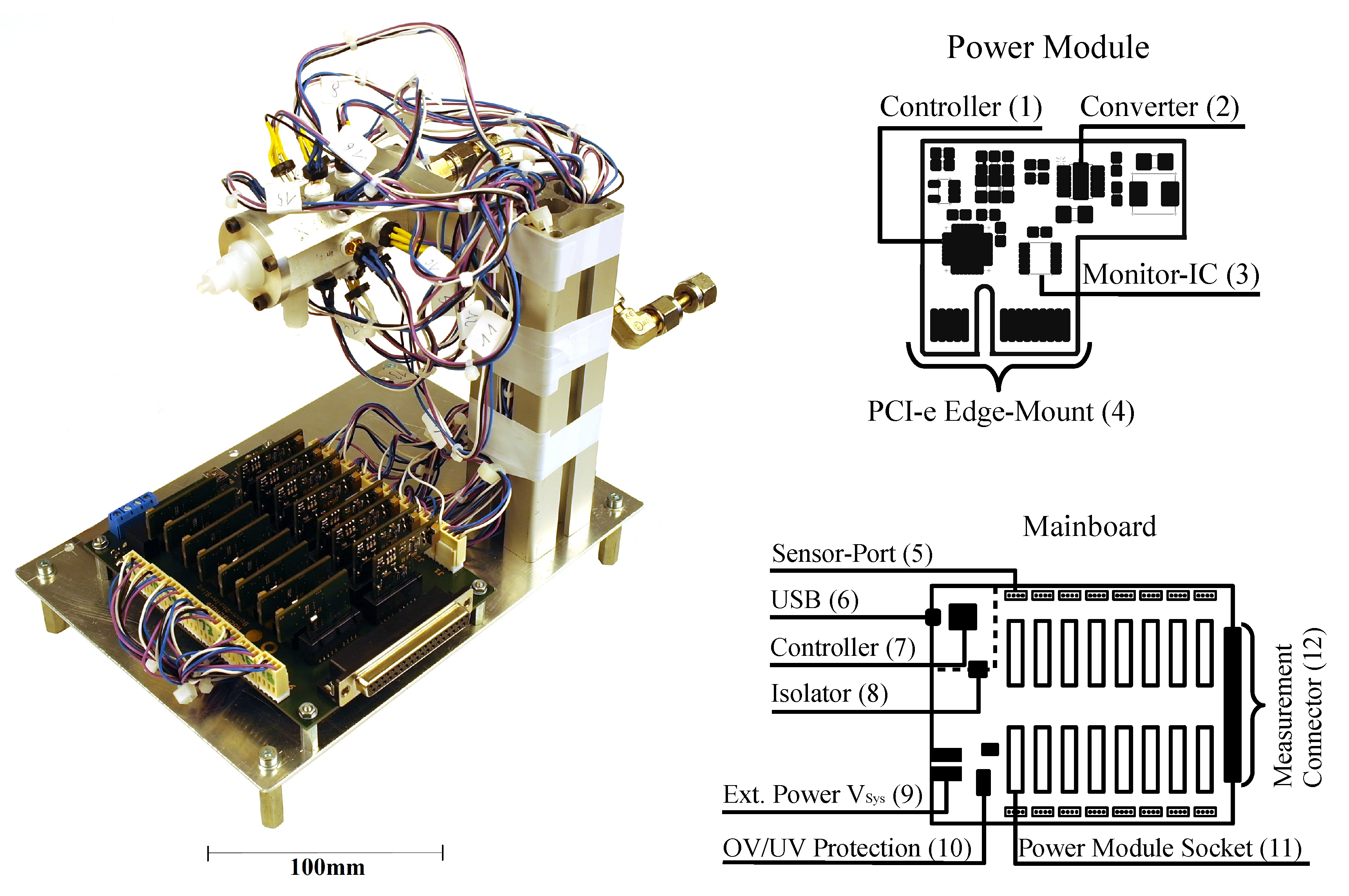
3.1. Mainboard
3.2. Power Module
3.3. Firmware
3.4. Communication Protocol
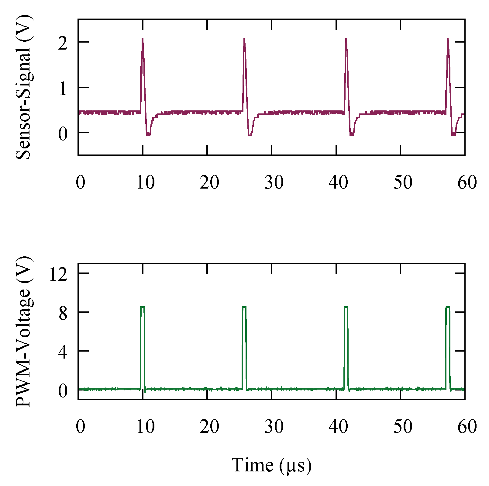
4. System Validation
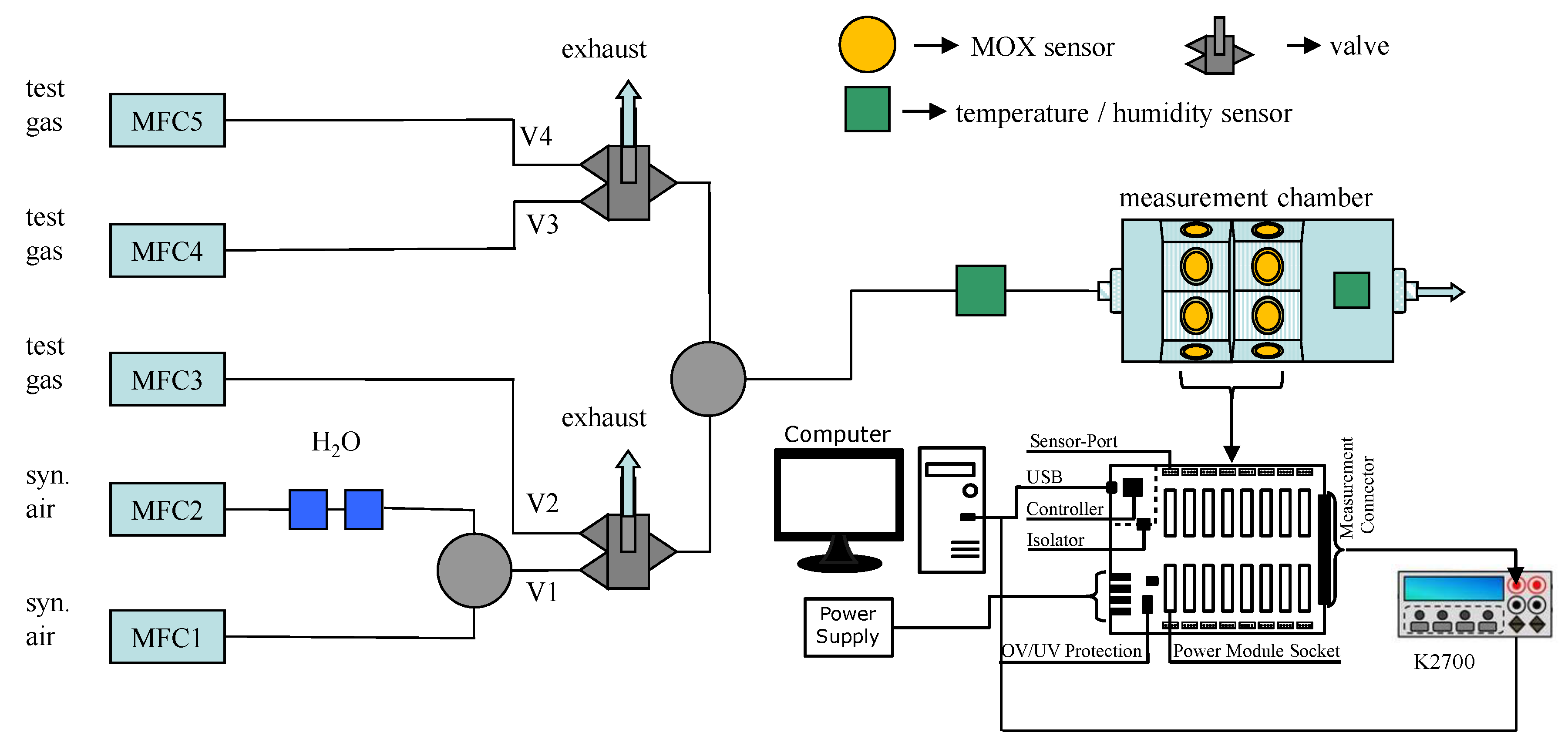
5. Application Example
6. Conclusions
Author Contributions
Funding
Conflicts of Interest
References
- Binions, R.; Naik, A. 13—Metal oxide semiconductor gas sensors in environmental monitoring. In Semiconductor Gas Sensors; Jaaniso, R., Tan, O.K., Eds.; Woodhead Publishing Series in Electronic and Optical Materials; Woodhead Publishing: Sawston, UK, 2013; pp. 433–466. [Google Scholar] [CrossRef]
- Gutmacher, D.; Foelmli, C.; Vollenweider, W.; Hoefer, U.; Wöllenstein, J. Comparison of gas sensor technologies for fire gas detection. Procedia Eng. 2011, 25, 1121–1124. [Google Scholar] [CrossRef]
- Heilig, A.; Bârsan, N.; Weimar, U.; Schweizer-Berberich, M.; Gardner, J.; Göpel, W. Gas identification by modulating temperatures of SnO2-based thick film sensors. Sens. Actuators B Chem. 1997, 43, 45–51. [Google Scholar] [CrossRef]
- Padilla, M.; Perera, A.; Montoliu, I.; Chaudry, A.; Persaud, K.; Marco, S. Drift compensation of gas sensor array data by Orthogonal Signal Correction. Chemom. Intell. Lab. Syst. 2010, 100, 28–35. [Google Scholar] [CrossRef]
- Lee, A.P.; Reedy, B.J. Temperature modulation in semiconductor gas sensing. Sens. Actuators B Chem. 1999, 60, 35–42. [Google Scholar] [CrossRef]
- Vergara, A.; Llobet, E.; Brezmes, J.; Vilanova, X.; Stankova, M.; Gracia, I.; Cane, C.; Correig, X. Optimized multi-frequency temperature modulation of microhotplate gas sensors. In Proceedings of the IEEE 2004 SENSORS, Vienna, Austria, 24–27 October 2004; Volume 3, pp. 1392–1395. [Google Scholar] [CrossRef]
- Fonollosa, J.; Fernández, L.; Huerta, R.; Gutiérrez-Gálvez, A.; Marco, S. Temperature optimization of metal oxide sensor arrays using Mutual Information. Sens. Actuators B Chem. 2013, 187, 331–339. [Google Scholar] [CrossRef]
- Wehrenfennig, C.; Schott, M.; Gasch, T.; Sauerwald, T.; Düring, R.A.; Vilcinskas, A.; Kohl, C.D. Laboratory characterization of metal-oxide sensors intended for in situ analyses of pheromones—SOMMSA approach. Phys. Status Solidi A 2012, 209, 935–939. [Google Scholar] [CrossRef]
- Zhang, G.; Xie, C.; Zhang, S.; Zhao, J.; Lei, T.; Zeng, D. Temperature-Programmed Technique Accompanied with High-Throughput Methodology for Rapidly Searching the Optimal Operating Temperature of MOX Gas Sensors. ACS Comb. Sci. 2014, 16, 459–465. [Google Scholar] [CrossRef] [PubMed]
- Zhang, J.; Qin, Z.; Zeng, D.; Xie, C. Metal-oxide-semiconductor based gas sensors: screening, preparation, and integration. Phys. Chem. Chem. Phys. 2017, 19, 6313–6329. [Google Scholar] [CrossRef] [PubMed]
- Yamazoe, N.; Sakai, G.; Shimanoe, K. Oxide Semiconductor Gas Sensors. Catal. Surv. Asia 2003, 7, 63–75. [Google Scholar] [CrossRef]
- Wang, C.; Yin, L.; Zhang, L.; Xiang, D.; Gao, R. Metal Oxide Gas Sensors: Sensitivity and Influencing Factors. Sensors 2010, 10, 2088–2106. [Google Scholar] [CrossRef]
- Cardinali, G.C.; Dori, L.; Fiorini, M.; Sayago, I.; Faglia, G.; Perego, C.; Sberveglieri, G.; Liberali, V.; Maloberti, F.; Tonietto, D. A Smart Sensor System for Carbon Monoxide Detection. Analog Integr. Circuits Signal Process. 1997, 14, 275–296. [Google Scholar] [CrossRef]
- Malfatti, M.; Stoppa, D.; Simoni, A.; Lorenzelli, L.; Adami, A.; Baschirotto, A. A CMOS Interface for a Gas-Sensor Array with a 0.5%-Linearity over 500 k/spl Omega/-to-1 G/spl Omega/ Range and 2.5/spl deg/C Temperature Control Accuracy. In Proceedings of the 2006 IEEE International Solid State Circuits Conference—Digest of Technical Papers, San Francisco, CA, USA, 6–9 February 2006; pp. 1131–1140. [Google Scholar] [CrossRef]
- Amos, M.; Segee, B. Micro-controller based Heater Control for Gas Sensors. In Proceedings of the 2001 American Society for Engineering Education Annual Conference & Exposition, Albuquerque, NM, USA, 24–27 June 2001; pp. 6.721.1–6.721.6. [Google Scholar]
- PID Theory Explained. Available online: http://www.webcitation.org/78PZ5UGOP (accessed on 16 May 2019).
- Hansford, G.M.; Freshwater, R.A.; Bosch, R.A.; Cox, R.A.; Jones, R.L.; Pratt, K.F.E.; Williams, D.E. A low cost instrument based on a solid state sensor for balloon-borne atmospheric O3 profile sounding. J. Environ. Monit. 2005, 7, 158–162. [Google Scholar] [CrossRef] [PubMed]
- Barrettino, D.; Graf, M.; Taschini, S.; Hafizovic, S.; Hagleitner, C.; Hierlemann, A. CMOS Monolithic Metal–Oxide Gas Sensor Microsystems. IEEE Sens. J. 2006, 6, 276–286. [Google Scholar] [CrossRef]
- Somov, A.; Baranov, A.; Spirjakin, D.; Passerone, R. Circuit Design and Power Consumption Analysis of Wireless Gas Sensor Nodes: One-Sensor Versus Two-Sensor Approach. IEEE Sens. J. 2014, 14, 2056–2063. [Google Scholar] [CrossRef]
- Martinelli, E.; Polese, D.; Catini, A.; D’Amico, A.; Natale, C.D. Self-adapted temperature modulation in metal-oxide semiconductor gas sensors. Sens. Actuators B Chem. 2012, 161, 534–541. [Google Scholar] [CrossRef]
- Sudarmaji, A.; Kitagawa, A. Temperature Modulation with Specified Detection Point on Metal Oxide Semiconductor Gas Sensors for E-Nose Application. Sens. Transducers 2015, 186, 93–103. [Google Scholar]
- Schultealbert, C.; Baur, T.; Schütze, A.; Böttcher, S.; Sauerwald, T. A novel approach towards calibrated measurement of trace gases using metal oxide semiconductor sensors. Sens. Actuators B Chem. 2017, 239, 390–396. [Google Scholar] [CrossRef]
- STMicroelectronics. STM32F410x8 Datasheet; Rev. 6; STMicroelectronics: Amsterdam, The Netherlands, 2017; Available online: https://www.st.com/resource/en/datasheet/stm32f410cb.pdf (accessed on 5 August 2019).
- I2C-Bus: What’s that? Available online: http://www.webcitation.org/78PYumH1g (accessed on 16 May 2019).
- Texas Instruments Incorporation. ISO154x—Low-Power Bidirectional I2C Isolators, December 2016 ed.; SLLSEB6D; Texas Instruments: Dallas, TX, USA, 2016; Available online: http://www.ti.com/lit/ds/symlink/iso1540.pdf (accessed on 5 August 2019).
- Linear Technology Corporation. LTC4365—Overvoltage, Undervoltage and Reverse Supply Protection Controller, September 2013 ed.; Rev. D; Linear Technology Corporation: Milpitas, CA, USA, 2013; Available online: https://www.analog.com/media/en/technical-documentation/data-sheets/4365fa.pdf (accessed on 5 August 2019).
- Linear Technology Corporation. LTC 2945—Wide Range I2C Power Monitor, September 2015 ed.; REV. B; Linear Technology Corporation: Milpitas, CA, USA, 2015; Available online: https://www.analog.com/media/en/technical-documentation/data-sheets/2945fb.pdf (accessed on 5 August 2019).
- AppliedSensor. AS-MLK—Natural Gas Sensor; AppliedSensor Sweden AB: Linköping, Sweden, 2012. [Google Scholar]
- Linear Technology Incorporated. LTC3600—15 V, 1.5 A Synchronous Rail-to-Rail Single Resistor Step-Down Regulator, June 2016 ed.; REV. D; Linear Technology Corporation: Milpitas, CA, USA, 2016; Available online: https://www.analog.com/media/en/technical-documentation/data-sheets/3600fd.pdf (accessed on 5 August 2019).
- IHLP Commercial Inductors. IHLP—High Saturation Coil Series Datasheet. Rev. 07.07.17. 2017. Available online: https://www.vishay.com/docs/34253/ihlp-2020bz-01.pdf (accessed on 5 August 2019).
- STMicroelectronics. STM32L431—Ultra-low-power Arm Cortex-M4 32-bit MCU. DS11451 Rev. 4. 2018. Available online: https://www.st.com/resource/en/datasheet/stm32l432kc.pdf (accessed on 5 August 2019).
- Texas Instruments Incorporation. LM 7321—Single Ch, RRIO, High Output Current & Unlimited Cap Load +/-15 V Op Amp, September 2015 ed.; SNOSAW8E; Texas Instruments: Dallas, TX, USA, 2015; Available online: http://www.ti.com/lit/ds/symlink/lm7322.pdf (accessed on 5 August 2019).
- UST Umweltsensortechnik GmbH. MOX Gas Sensors—Calculation of the Operation Temperature, March 2016 ed. 2016. Available online: http://www.umweltsensortechnik.de/fileadmin/assets/downloads/gassensoren/single/TechInfo_MOX-gas-sensors_Calculation_of_the_operating_temperature_Rev1603.pdf (accessed on 5 August 2019).
- Taiwan Semiconductor Co. Ltd. TS317—3-Terminal Adjustable Positive Voltage Regulator Datasheet, Version E15; 2015. Available online: https://www.taiwansemi.com/products/datasheet/TS317_E15.pdf (accessed on 5 August 2019).
- Tietze, U.; Schenk, C.; Gamm, E. Halbleiter-Schaltungstechnik; Springer: Berlin/Heidelberg, Germany, 2012. [Google Scholar]


| Head | I2C Address | Command | Data | CRC | Trail | |||
|---|---|---|---|---|---|---|---|---|
| Bytes | 1 | 1 | 1 | 0:10 | 4 | 3 | ||
| Value | 0 × F0 | 0 × 00:0 × 0F | Variable | Variable | Variable | 0 × FF | 0 × 0D | 0 × 0A |
© 2019 by the authors. Licensee MDPI, Basel, Switzerland. This article is an open access article distributed under the terms and conditions of the Creative Commons Attribution (CC BY) license (http://creativecommons.org/licenses/by/4.0/).
Share and Cite
Hammer, C.; Warmer, J.; Sporrer, S.; Kaul, P.; Thoelen, R.; Jung, N. A Compact, Reliable and Efficient 16 Channel Power Supply for the Automated Screening of Semiconducting Metal Oxide Gas Sensors. Electronics 2019, 8, 882. https://doi.org/10.3390/electronics8080882
Hammer C, Warmer J, Sporrer S, Kaul P, Thoelen R, Jung N. A Compact, Reliable and Efficient 16 Channel Power Supply for the Automated Screening of Semiconducting Metal Oxide Gas Sensors. Electronics. 2019; 8(8):882. https://doi.org/10.3390/electronics8080882
Chicago/Turabian StyleHammer, Christof, Johannes Warmer, Sebastian Sporrer, Peter Kaul, Ronald Thoelen, and Norbert Jung. 2019. "A Compact, Reliable and Efficient 16 Channel Power Supply for the Automated Screening of Semiconducting Metal Oxide Gas Sensors" Electronics 8, no. 8: 882. https://doi.org/10.3390/electronics8080882
APA StyleHammer, C., Warmer, J., Sporrer, S., Kaul, P., Thoelen, R., & Jung, N. (2019). A Compact, Reliable and Efficient 16 Channel Power Supply for the Automated Screening of Semiconducting Metal Oxide Gas Sensors. Electronics, 8(8), 882. https://doi.org/10.3390/electronics8080882