Article

On Performance Analysis of Underlay Cognitive Radio-Aware Hybrid OMA/NOMA Networks with Imperfect CSI

1
Wireless Communications Research Group, Faculty of Electrical and Electronics Engineering, Ton Duc Thang University, Ho Chi Minh City 700000, Vietnam
2
Faculty of Electronics Technology, Industrial University of Ho Chi Minh City (IUH), Ho Chi Minh City 700000, Vietnam
3
School of Intelligent Mechatronics Engineering, Sejong University, Seoul 05006, Korea
*
Authors to whom correspondence should be addressed.
Electronics 2019, 8(7), 819; https://doi.org/10.3390/electronics8070819
Submission received: 5 June 2019 / Revised: 19 July 2019 / Accepted: 19 July 2019 / Published: 22 July 2019
(This article belongs to the Special Issue Cooperative Communications for Future Wireless Systems)

Abstract

:
This study considers the outage and throughput performance of downlink in the secondary network of cognitive radio assisted non-orthogonal multiple access (NOMA) systems. Both orthogonal multiple access (OMA) mode and NOMA mode are investigated with respect to status of decoding operation of each user. Depending on the transmit signal-to-noise ratio (SNR) at the primary source and interference constraint from the primary network, the closed-form expressions of the outage probability for two users are obtained and compared in terms of performance. To obtain further insights, an asymptotic analysis of the outage probability in the high SNR regime is presented. Optimal throughput also provides insight in the computation of the power allocation factor. Furthermore, power allocation factor, target rates, and transmit SNR are evaluated to obtain reasonable outage performance. Monte Carlo simulations are conducted to confirm the analytical results.

1. Introduction

As a candidate technique for forthcoming 5G networks, the non-orthogonal multiple access (NOMA) network has recently drawn in considerable attention [1,2,3,4,5]. In particular, NOMA exhibits high spectral efficiency and it outperforms the traditional orthogonal multiple access (OMA) scheme [1,2,3]. In order to serve the demand of a large number of users, the different users are allocated the total radio resources by a NOMA or OMA. The main difference is that NOMA controls the interference by utilizing the successive interference cancellation (SIC) technique and this function is different with OMA which eliminates the interference completely. In general, by exploiting a new dimension, capable of supporting ultrahigh connectivity for future applications can be performed via dimension of power domain NOMA. In practical NOMA systems, to achieve low complexity, the SIC decoding technique needs to satisfy the performance of the NOMA system and it requires the user grouping as an important issue. Unlike the well-known water-filling scheme, NOMA intends to deliver higher power to the users who meet weaker channel conditions, and hence the user fairness is satisfied [1,2]. In the recent works regarding the NOMA system, the improved performance can be achieved as employing a relaying network [4,5,6,7,8,9,10] with NOMA to introduce cooperative NOMA [11].
As other applications of NOMA, it can be combined with cognitive radio. Cognitive radio is a promising technique to improve the spectrum efficiency by allocating the secondary users to dynamically access the licensed spectrum [12,13]. The underlay and/or overlay spectrum sharing strategies are widely implemented in the current research about the cognitive radio networks. For the overlay strategy, the secondary users detect the underutilized licensed spectrum to access which can avoid collision with the primary transmission [14,15]. For the underlying strategy, the secondary network shares the licensed spectrum with the primary users by controlling the interference with the primary receivers under a threshold [16,17]. In [18], the concept of interweave cognitive radio (CR) systems together with Opportunistic interference alignment (OIA) are introduced as a new technique to enable the multiple-input multiple-output (MIMO) secondary user (SU) to exploit the inherent spatial spectrum holes of the MIMO primary user’s (PU) communication link. As two popular types in terms of interference constraints, the average interference power (AIP) over all different fading states and limit of the peak interference power (PIP) at each fading state are considered in the CR network in [19].
It is envisioned that the combination of NOMA with CR is capable of further improving the lspectrum efficiency (SE). As a benefit of its low complexity, spectrum sharing has been widely applied. In [20,21,22], the authors analyzed the performance of a spectrum sharing CR combined with NOMA. It was shown that the SE can be significantly improved by using NOMA in CR compared to that achieved by using OMA in CR. The authors in [16,17,18,19,20,21] have already studied fairness in NOMA users; fairness in resource allocation still needs to be considered in which case NOMA is better than that of OMA. One difficult problem needs be evaluated that is conditional on the wireless channel.
Most previous works regarding NOMA systems considered in the above assume perfect channel state information (CSI). However, in real conditions, a NOMA network needs to be investigated in the worst case of imperfect channel state information (CSI) [23,24,25,26,27,28]. The authors in [24] examined beamforming vectors and the power allocation to maximize the system utility of multiple-input and multiple-output NOMA (MIMO-NOMA) with respect to probabilistic constraints. The raised solution is that introducing first-order approximation and semidefinite programming (SDP) to form an efficient successive convex approximation (SCA) scheme. Several multiplexed users can be proceeded in NOMA transmission and the imperfect CSI were considered to evaluate in terms of resource allocation in NOMA as in [25]. They proposed an iterative algorithm related to power allocation and user scheduling with aiming to maximize the system energy efficiency. They also compared with the system performance benchmark by exploiting optimal user scheduling based on exhaustive search [25]. The exact closed-form formulas in terms of the outage probability of two secondary destination users are evaluated in the case of imperfect channel state information [26]. Then, the optimal power allocation coefficients corresponding with different distances of users are found to satisfy the outage performance fairness for both destination users. In order to maximize the energy efficiency (EE) in a NOMA network, the authors in [27] explored an optimum user power allocation solution with imperfect CSI at the transmitter and then user quality of service constraint is further examined. They confirmed that the users with CSI error and with low rate requirement; NOMA exhibits a better performance in comparison with traditional orthogonal multiple access (OMA) in terms of EE. The authors in [28] presented a power allocation strategy to achieve maximal energy efficiency as exploiting downlink NOMA in heterogeneous networks and they examined system performance under the impact of imperfect CSI situations.
To fill the aforementioned gap, we in this study emphasize the outage and throughput performance of a CR-NOMA in which the OMA/NOMA selection mode is activated by comparison on a channel condition. Downlink performance of NOMA while employing hybrid OMA/NOMA is studied [29]. Their system model allows for switching between orthogonal multiple access (OMA) and non-orthogonal multiple access (NOMA), signalling the achievement of improved performance of the far user significantly, and in this case performance of the close user does not degrade the below value, which is obtained as OMA implemented alone [29]; however, such advantage of the OMA/NOMA selection mode applied in the CR-NOMA network has not been explored yet. This is different from recent work [30] in which they studied a cooperative CR-NOMA network with several assumptions at the secondary network such as perfect CSI at receivers, and NOMA is fully used for the whole system. In this paper, the main goal is that system performance needs to be evaluated in terms of exploiting how the OMA/NOMA selection scheme maintains performance of secondary destination users. The second challenge in this proposed CR network as imperfect CSI needs to be investigated since relay is not able to achieve the knowledge of wireless channels. The main contributions of this study are summarized as follows:
  • A CR network is recommended to permit a secondary network containing the secondary users (SU) that intend to access the 5G spectrum in two situations including the absence and presence of the primary user (PU). In particular, SU is able to choose the hybrid OMA/NOMA scheme to communicate with two destinations and this scheme can improve the spectrum utilization greatly compared with the normal NOMA or normal OMA scheme.
  • Impacts of imperfect CSI on system evaluation have not been well studied in [25,26,27,28,29,30]. We first propose a policy to achieve improved performance of the far user by assigning the close user as relay. Such advantage of a hybrid scheme of OMA/NOMA can be obtained as performing simulations to compare two models. Moreover, we investigate the imperfect CSI to achieve realistic evaluations on the CR network in practical applications. To the authors’ best knowledge, this is the first work that considers hybrid OMA/NOMA selection and imperfect CSI in terms of CR downlink transmission.
  • We derive the closed-form expressions of the outage probability. Under the high complexity in computation, it is necessary to explore asymptotic outage performance of each user to provide an insight for such CR network. In addition, we develop an approach to achieve optimal outage performance evaluations in NOMA mode as considering varying values of power allocation factors assigned to two users.
  • Due to the difficulty of exhibiting outage performance for two users through these closed-form expressions, asymptotic expressions are introduced to verify this outage event in the simple manner. It is expected that approximate outage performance matches with corresponding analytical results at a certain considered range.
  • Simulation results show the performance comparison in various scenarios of the proposed scheme in terms of the outage probability and throughput, which show significant differences as a comparison of several values of levels of CSI imperfections.
The remainder of this paper is organized as follows: Section 2 defines the system and channel model with a definition of OMA/NOMA selection protocol adopted in the CR network under imperfect CSI. Section 3 derives new analytical outage probability expressions of two NOMA users. Section 4 is introduced to examine the insight, i.e., asymptotic outage behavior and throughput are further provided and optimal value of power allocation factor can be achieved. Numerical results are presented in Section 5. Finally, the paper is concluded in Section 6.
Notations: To ease illustrations of expressions, Pr . symbolizes probability, the probability density function (PDF) and the cumulative distribution function (CDF) of a random variable X are represented as F X . and f x . , respectively, and E . stands for the expectation operator, U . denotes the unit step function.

2. System Model

As illustrated in Figure 1, a downlink of the NOMA scenario with a secondary network containing a base station (BS) intends to serve NOMA users U 1 and U 2 . It is assumed that U 1 is the close user and U 2 is the far user. These nodes are located in the secondary network (SN) where it is limited by the primary network (PN) in terms of transmit power. In this study, all nodes are equipped with a single antenna and operated in a half-duplex mode. Channel coefficients following Rayleigh fading from node a to node b are denoted by h a b while h 1 , h 2 are links from base station to user U 1 , U 2 , respectively. To evaluate the impact of imperfect CSI, these channels are modeled by using the minimum mean square error channel estimation error as in [27]. In particular, it is expressed as h j = h ^ j + h ˜ j , j 1 , 2 , 12 , S P , 1 P , where h ^ j is the estimated channel coefficient and h ˜ j stands for the error term. In addition, h ˜ j is modeled as a complex Gaussian distributed random variable with σ j 2 .
The distribution of fading channels exhibit channel gains as λ j = d j χ , where d j is the distance between two nearby nodes, and χ is the path-loss exponent. Moreover, the interference from the primary sources (PT) to the users of the SN is denoted by I P . To perform NOMA, α ( 0 < α < 1 ) is a power allocation factor and x 1 , x 2 are mixture signals that proceed at the secondary source to transmit to far away destinations. In this scenario, interference from the PN to SN is I P C N 0 , N 0 η , 0 < η < 1 , N 0 is additive white Gaussian noise(AWGN) noise terms as [30]. In the context of CR, the power constraint designed at the SN, and hence the related transmit power is given P k = min I t h h k P 2 , P ¯ k , ( k S , 1 ) . Two superimposed signals transmitting from the source satisfy E x 1 2 = E x 2 2 = 1 .
We first compute the received signal at U i under the impact of interference from the primary network. It can be given by
y U i N O M A = α P S x 1 + 1 α P S x 2 h ^ i + h ˜ i + I P + v U i = α P S x 1 + 1 α P S x 2 h ^ i + P S α P S x 1 + 1 α P S x 2 h ˜ i + I P + v U i effective noise ,
where the noise term following additive white Gaussian noise (AWGN) is v U i C N 0 , N 0 . The following signal-to-noise ratio (SNR) first needs to be computed to further evaluate the system performance via main metrics, i.e., outage probability and throughput.

2.1. Calculation of SNR

First of all, the signal-to-interference-plus-noise ratios (SINRs) for detecting signal x 2 at the U 1 can be calculated as
γ S 1 2 N O M A = α ρ S h ^ 1 2 ρ S 1 α h ^ 1 2 + ρ S σ 1 2 + η + 1 ,
where ρ S = P N 0 is the so-called transmit SNR at the secondary source.
After applying SIC, the SINR at the U 1 for detecting signal x 1 at the U 1 can be calculated as
γ S 1 1 N O M A = ρ S 1 α h ^ 1 2 ρ S σ 1 2 + η + 1 .
Regarding signal detection at U 2 , the SINR for detecting signal x 2 at the U 2 can be calculated as
γ S 2 2 N O M A = α ρ S h ^ 2 2 ρ S 1 α h ^ 2 2 + ρ S σ 2 2 + η + 1 .

2.2. OMA/NOMA Selection Mode

Now, we consider a user selection mechanism in terms of OMA or NOMA. Before transmitting, the primary source receives feedback information to select OMA or NOMA mode, U 1 is required to notify to nearby source. Next, we consider a set Q representing for ability to choose an OMA/NOMA mode.
It can be recalled on condition to detection, user U 1 can successfully decode x 2 if following the inequality is satisfied:
1 2 log 2 1 + γ S 1 2 N O M A R 2 .
Similarly, it can be a determined condition to detect signal x 1 as
1 2 log 2 1 + γ S 1 1 N O M A R 1 .
By definition, SNRs of users U 1 , U 2 depend on the corresponding target rates R 1 , R 2 , i.e., γ 1 = 2 2 R 1 1 and γ 2 = 2 2 R 2 1 . Comparing Equations (5) and (6), the following condition which is related to new variable Q can be introduced:
Q = ρ S h ^ 1 2 Θ ^ ρ S σ 1 2 + η + 1 ,
where ε 2 = γ 2 α 1 α γ 2 U α 1 α γ 2 , ε 1 = γ 1 1 α U α 1 α γ 2 and Θ ^ = max ε 2 , ε 1 .
In this context, user U 2 not only receives signal transferred directly from the secondary source but also achieves signal transferred from U 1 . x ^ 2 achieved after successful decoding at user U 1 can be introduced to further transmit to the far user U 2 . The received signal can be seen at U 2 as
y 12 N O M A = P 1 x ^ 2 h ^ 12 + h ˜ 12 + I P + v 2 ,
where v 2 is a AWGN noise term with variance of N 0 . P 1 stands for transmit power of user U 1 .
Regarding the link between user U 1 and U 2 , SNR is calculated at user U 2
γ 1 2 N O M A = ρ 1 h ^ 12 2 ρ 1 σ 12 2 + η + 1 ,
where ρ 1 = P 1 N 0 .
In the worse case, user U 1 can not decode the signal of U 2 , and we adopt the hybrid scheme reported in [29]
The adaptive scheme uses OMA whenever NOMA fails ( Q = 0 ) and it means that
S e l e c t i o n M o d e = O M A , N O M A , Q = 0 , Q 0 .
We show later that OMA still serves transmission from the secondary source to two destinations U 1 , U 2 .

2.3. OMA Mode

In case of Q = 0 , each user U 1 , U 2 , OMA transmission is adopted. Firstly, the received signal at each user can be formulated as
y U i O M = P S x i h ^ i + h ˜ i + I P + v U i ,
where superscript OM denotes the OMA mode. Then, the SNRs are computed at user U 1 , U 2 , respectively,
γ S 1 O M = ρ S h ^ 1 2 ρ S σ 1 2 + η + 1 ,
and
γ S 2 O M = ρ S h ^ 2 2 ρ S σ 2 2 + η + 1 .

3. Outage Performance Analysis

In such SN in CR, the far user needs to be improved in terms of outage performance. In particular, user U 2 has higher priority to consider outage behavior compared with the close user who occupies better channel condition.

3.1. Outage Probability of the U 2

The outage probability (OP) related to the message at user U i , i = 1 , 2 is defined as the probability that the SINR is below a predefined SINR ε i . If the SIC user ( U 1 ) meets the outage behavior, the SIC user ( U 2 ) does not require signal from a U 1 U 2 link. In addition, the outage of the SIC user depends on both its own received signal and from the U 1 U 2 link.
Before computing the OP for each user, it can be computed based on these functions including the probability density function (PDF) and the cumulative distribution function (CDF) of dedicated channel respectively as
f h j 2 x = 1 λ j e x λ j
and
F h j 2 x = 1 e x λ j .
The U 2 combines the signal in a direct link primary source to U 2 and link U 1 U 2 . It is worth noting that NOMA is activated ( Q 0 ). Clearly, outage probability of the U 2 is given by:
O P U 2 = Pr γ 1 2 N O M A < γ 2 , Q 0 A 1 , N O M A + Pr γ S 2 O M < γ 2 , Q = 0 A 2 , O M A .
Particularly, the first component can be computed as
A 1 = Pr γ 1 2 N O M A < γ 2 Pr Q 0 .
Due to the definition of Q, it can be expressed that
Pr Q 0 = Pr ρ S h ^ 1 2 Θ ^ ρ S σ 1 2 + η + 1 .
Proposition 1.
The condition produces NOMA and it can be computed by
Pr Q 0 = λ 1 ρ I e λ 1 ρ I + λ S P Θ ^ η + 1 λ S P λ 1 ρ ¯ S Θ ^ σ 1 2 λ 1 λ 1 ρ I + λ S P Θ ^ η + 1 + e Θ ^ ρ ¯ S σ 1 2 + η + 1 λ 1 ρ ¯ S 1 e ρ I λ S P ρ ¯ S .
Proof. 
See Appendix A. □
Constraint by PN related to transmit power at primary source, Pr γ 1 2 N O M A < γ 2 is determined by
Pr γ 1 2 N O M A < γ 2 = Pr h ^ 12 2 < γ 2 ρ ¯ 1 σ 12 2 + η + 1 ρ ¯ 1 , h 1 P 2 < ρ I ρ ¯ 1 + Pr h ^ 12 2 < γ 2 ρ I σ 12 2 + η + 1 h 1 P 2 ρ I , h 1 P 2 > ρ I ρ ¯ 1 .
After simple computation, it can be achieved that
Pr γ 1 2 N O M A < γ 2 = 1 e ρ I λ 1 P ρ ¯ 1 1 e γ 2 ρ ¯ 1 σ 12 2 + η + 1 λ 12 ρ ¯ 1 + e ρ I λ 1 P ρ ¯ 1 λ 12 ρ I e γ 2 λ 1 P η + 1 + λ 12 ρ I λ 1 P λ 12 ρ ¯ 1 γ 2 σ 12 2 λ 12 γ 2 λ 1 P η + 1 + λ 12 ρ I .
It is expected to be an OMA mode, and the following outage probability needs to be calculated as
Pr γ S 2 O M < γ 2 = Pr ρ ¯ S h ^ 2 2 ρ ¯ S σ 2 2 + η + 1 < γ 2 , ρ ¯ S < ρ I h S P 2 + Pr ρ I h ^ 2 2 ρ I σ 2 2 + η + 1 h S P 2 < γ 2 , ρ ¯ S > ρ I h S P 2 .
It is rewritten as
Pr γ S 2 O M < γ 2 = 1 e ρ I λ S P ρ ¯ S 1 e γ 2 ρ ¯ S σ 2 2 + η + 1 λ 2 ρ ¯ S + e ρ I λ S P ρ ¯ S λ 2 ρ I e γ 2 λ S P η + 1 + λ 2 ρ I λ S P λ 2 ρ ¯ S γ 2 σ 2 2 λ 2 γ 2 λ S P η + 1 + λ 2 ρ I .
In a similar way, the condition produces OMA and it can be expressed by
Pr Q = 0 = Pr ρ ¯ S h 1 2 < Θ ^ ρ ¯ S σ 1 2 + η + 1 , ρ ¯ S < ρ I h S P 2 + Pr ρ I h S P 2 h 1 2 < Θ ^ ρ I h S P 2 σ 1 2 + η + 1 , ρ ¯ S > ρ I h S P 2 .
It is further formulated as
Pr Q = 0 = 1 e ρ I λ S P ρ ¯ 1 e Θ ^ ρ ¯ σ 1 2 + η + 1 λ 1 ρ ¯ + e ρ I λ S P ρ ¯ e Θ ^ σ 1 2 λ 1 λ 1 ρ I Θ ^ λ S P η + 1 + λ 1 ρ I e Θ ^ λ S P η + 1 + λ 1 ρ I λ S P λ 1 ρ ¯ .
Finally, outage performance of user U 2 can be evaluated as
O P U 2 = 1 e ρ I λ 1 P ρ ¯ 1 1 e γ 2 ρ ¯ 1 σ 12 2 + η + 1 λ 12 ρ ¯ 1 + e ρ I λ 1 P ρ ¯ 1 λ 12 ρ I e γ 2 λ 1 P η + 1 + λ 12 ρ I λ 1 P λ 12 ρ ¯ 1 γ 2 σ 12 2 λ 12 γ 2 λ 1 P η + 1 + λ 12 ρ I × λ 1 ρ I e λ 1 ρ I + Θ ^ λ S P η + 1 λ S P λ 1 ρ ¯ S Θ ^ σ 1 2 λ 1 λ 1 ρ I + Θ ^ λ S P η + 1 + e Θ ^ ρ ¯ S σ 1 2 + η + 1 λ 1 ρ ¯ S 1 e ρ I λ S P ρ ¯ S + 1 e ρ I λ S P ρ ¯ S 1 e γ 2 ρ ¯ S σ 2 2 + η + 1 λ 2 ρ ¯ S + e ρ I λ S P ρ ¯ S λ 2 ρ I e γ 2 λ S P η + 1 + λ 2 ρ I λ S P λ 2 ρ ¯ S γ 2 σ 2 2 λ 2 γ 2 λ S P η + 1 + λ 2 ρ I × 1 e ρ I λ S P ρ ¯ S 1 e Θ ^ ρ ¯ S σ 1 2 + η + 1 λ 1 ρ ¯ S + e ρ I λ S P ρ ¯ S λ 1 ρ I e Θ ^ λ S P η + 1 + λ 1 ρ I λ S P λ 1 ρ ¯ S Θ ^ σ 1 2 λ 1 Θ ^ λ S P η + 1 + λ 1 ρ I .

3.2. Outage Probability of the U 1

By noticing the existence of the selection mode in terms of whether it is OMA/NOMA, the outage behavior of user U 1 can be shown as
O P U 1 = Pr γ S 1 O M < γ 1 , γ S 1 2 N O M A < γ 2 + Pr γ S 1 O M < γ 1 , γ S 1 2 N O M A γ 2 , γ S 1 1 N O M A < γ 1 .
Thus, the outage of U 1 can be formulated as
O P U 1 = Pr γ S 1 O M < γ 1 .
Substituting Equation (12) into Equation (17), it can be obtained that
O P U 1 = Pr ρ S h ^ 1 2 ρ S σ 1 2 + η + 1 < γ 1 .
Then, O P U 1 can be rewritten as
O P U 1 = Pr h ^ 1 2 < γ 1 ρ ¯ S σ 1 2 + η + 1 ρ ¯ S , h S P 2 < ρ I ρ ¯ S + Pr h ^ 1 2 < γ 1 ρ I σ 1 2 + η + 1 h S P 2 ρ I , h S P 2 > ρ I ρ ¯ S .
Similarly, with the help of hlLabel (14) and, performing algebraic manipulation, the final result of O P U 1 is
O P U 1 = 1 e ρ I λ S P ρ ¯ S 1 e γ 1 ρ ¯ S σ 1 2 + η + 1 λ 1 ρ ¯ S + e ρ I λ S P ρ ¯ S λ 1 ρ I e γ 1 λ S P η + 1 + λ 1 ρ I λ S P λ 1 ρ ¯ S γ 1 σ 1 2 λ 1 γ 1 λ S P η + 1 + λ 1 ρ I .

4. Asymptotic and Throughput Analysis

4.1. Asymptotic Analysis

At high transmit SNR at the primary source, the complex style of outage probability can be approximated. Use a linear approximation of the exponential as below.
In case of ρ ¯ = ρ ¯ S = ρ ¯ 1 , the outage performance of U 1 can be computed as
O P U 1 ρ ¯ = 1 λ 1 ρ I e γ 1 σ 1 2 λ 1 γ 1 λ S P η + 1 + λ 1 ρ I .
Regarding two approximate terms to achieve the final expression of outage probability for U 2 , these components can be calculated as
A 1 ρ ¯ λ 1 ρ I e Θ ^ σ 1 2 λ 1 λ 1 ρ I + λ S P η + 1 1 λ 12 ρ I e γ 2 λ 1 P η + 1 + λ 12 ρ I λ 1 P λ 12 ρ ¯ 1 γ 2 σ 12 2 λ 12 γ 2 λ 1 P η + 1 + λ 12 ρ I ,
and
A 2 ρ ¯ = 1 λ 2 ρ I e γ 2 σ 2 2 λ 2 γ 2 λ S P η + 1 + λ 2 ρ I 1 λ 1 ρ I e Θ ^ σ 1 2 λ 1 Θ ^ λ S P η + 1 + λ 1 ρ I .
Then, the lower bound of such outage performance of U 2 can be given by
O P U 2 ρ ¯ = λ 1 ρ I e Θ ^ σ 1 2 λ 1 λ 1 ρ I + λ S P Θ ^ η + 1 1 λ 12 ρ I e γ 2 σ 12 2 λ 12 γ 2 λ 1 P η + 1 + λ 12 ρ I + 1 λ 2 ρ I e γ 2 σ 2 2 λ 2 γ 2 λ S P η + 1 + λ 2 ρ I 1 λ 1 ρ I e Θ ^ σ 1 2 λ 1 Θ ^ λ S P η + 1 + λ 1 ρ I .
In particular, as ρ I , user U 1 exhibits outage probability as
O P U 1 ρ I = 1 e γ 1 ρ ¯ σ 1 2 + η + 1 λ 1 ρ ¯ ,
while two components related to computation of U 2 are formulated respectively as
A 1 ρ I e Θ ^ ρ ¯ σ 1 2 + η + 1 λ 1 ρ ¯ 1 e γ 2 ρ ¯ σ 12 2 + η + 1 λ 12 ρ ¯
and
A 2 ρ I = 1 e γ 2 ρ ¯ σ 2 2 + η + 1 λ 2 ρ ¯ 1 e Θ ^ ρ ¯ σ 1 2 + η + 1 λ 1 ρ ¯ .
Next, the approximate performance of U 2 is expressed by
O P U 2 ρ I = e Θ ^ ρ ¯ σ 1 2 + η + 1 λ 1 ρ ¯ 1 e γ 2 ρ ¯ σ 12 2 + η + 1 λ 12 ρ ¯ + 1 e γ 2 ρ ¯ σ 2 2 + η + 1 λ 2 ρ ¯ 1 e Θ ^ ρ ¯ σ 1 2 + η + 1 λ 1 ρ ¯ .

4.2. Throughput

By exploiting outage behavior of each user, the corresponding throughput can be achieved as
T i = 1 2 R i 1 O P U i .

4.3. Optimal Selection of α in NOMA Mode

To find the optimum power allocation factor in the CR network as NOMA activated α * of power factor α , the derived expressions for Equation (32) need to be considered in addition to a numerical search for the value of α that minimizes outage.
Since there is a difficulty in solving optimal outage in high complexity expressions in (32), the alternative method needs to be introduced. Fortunately, an approximation to α * can be obtained in a simple manner from the condition of Q.
It is worth noting that an approximate value of α * can be achieved by choosing α to increase the cardinality of Q. It is clear from Equation (7) that this can be achieved by choosing α to minimize Θ ^ = max ε 2 , ε 1 .
It is noted that γ S 1 2 N O M A > γ 2 happens only when α > γ 2 1 + γ 2 . We then observe that ε 2 = γ 2 α 1 α γ 2 decreases continuously when γ increases from γ 2 1 + γ 2 to 1. In addition, ε 1 = γ 1 1 α continuously increases when γ increases from γ 2 1 + γ 2 to 1. Then, a value of α can be obtained to minimize the Θ ^ = max ε 2 , ε 1 that requires ε 2 and ε 1 to equal [29]
ε 2 = ε 1 α * = 1 1 + γ 2 1 + 1 / γ 1 1 .

5. Extended Scheme of Multiple Antenna at the BS

In this section, this paper extends our system model to a complex case, i.e., multiple antennae are equipped at the BS. In such situation, the maximum ratio transmission (MRT) is used with a beamforming vector to achieve an optimal transmission scheme as in [31], with w Q = 1 , Q 1 ; 2 ; 12 .
w Q = h Q h Q ,
where . denotes the Euclidean norm of a matrix. In addition, then, the received signal at user U i is expressed as
y U i N O M A , m u l = α P S x 1 + 1 α P S x 2 w i h ^ i + P S α P S x 1 + 1 α P S x 2 w i h ˜ i + I P + n U i effective noise ,
where, h 1 and h 2 are the M × 1 and H × 1 channel vector, respectively (H, M are the number of antennae). The corresponding terms of SINR in this case can be given respectively as
γ S 1 2 N O M A , m u l = α ρ S h ^ 1 2 ρ S 1 α h ^ 1 2 + ρ S σ 1 2 + η + 1 ,
γ S 2 2 N O M A , m u l = α ρ S h ^ 2 2 ρ S 1 α h ^ 2 2 + ρ S σ 2 2 + η + 1 ,
and
γ 1 2 N O M A , m u l = ρ 1 h ^ 12 2 ρ 1 σ 12 2 + η + 1 .
For OMA circumstances, we have the following SINR expressions:
γ S 1 O M , m u l = ρ S h ^ 1 2 ρ S σ 1 2 + η + 1
and
γ S 2 O M , m u l = ρ S h ^ 2 2 ρ S σ 2 2 + η + 1 .

5.1. Outage Probability of U2

It is noted that CDF and PDF are [31]
f h Q 2 x = x N 1 e x λ Q Γ N λ Q N ,
where Γ x = x 1 ! is the gamma function and
F h Q 2 x = 1 e x λ Q p = 0 P 1 x p Γ p + 1 λ Q p .
Similarly, the outage performance of U 2 is given as
O P U 2 m u l = Pr γ 1 2 N O M A < γ 2 , Q 0 A 1 m u l , N O M A + Pr γ S 2 O M < γ 2 , Q = 0 A 2 m u l , O M A .
Then, we can calculate Pr Q 0 in this scheme as
Pr Q 0 = Pr ρ S h ^ 1 2 > Θ ^ ρ S σ 1 2 + η + 1 .
Proposition 2.
The condition produces NOMA and it can be computed by
Pr Q 0 = e Θ ^ ρ ¯ S σ 1 2 + η + 1 λ 1 ρ ¯ S m = 1 M 1 Θ ^ ρ ¯ S σ 1 2 + η + 1 m Γ m + 1 ρ ¯ S λ 1 m 1 e ρ I λ S P ρ ¯ S + m = 0 M 1 n = 0 m m n Θ ^ m ρ I λ 1 + λ S P Θ ^ η + 1 n 1 ρ I σ 1 2 m n e Θ ^ σ 1 2 λ 1 Γ m + 1 ρ I λ 1 m n 1 η + 1 λ S P n Γ n + 1 , ρ I λ 1 + λ S P Θ ^ η + 1 λ S P ρ ¯ S λ 1 .
Proof. 
See Appendix B. □
Then, some manipulations can be derived as below:
Pr γ 1 2 N O M A , m u l < γ 2 = Pr ρ 1 h ^ 12 2 ρ 1 σ 12 2 + η + 1 < γ 2 = 1 e γ 2 ρ ¯ 1 σ 12 2 + η + 1 ρ ¯ 1 λ 12 h = 0 H 1 γ 2 ρ ¯ 1 σ 12 2 + η + 1 h Γ p + 1 ρ ¯ 1 λ 12 h 1 e ρ I ρ ¯ 1 λ 1 P + e ρ I ρ ¯ 1 λ 1 P h = 0 H 1 l = 0 h h l γ 2 h ρ I σ 12 2 h l λ 1 P γ 2 η + 1 + ρ I λ 12 l 1 e γ 2 σ 12 2 λ 12 Γ p + 1 ρ I λ 12 h l 1 η + 1 λ 1 P l × Γ l + 1 , λ 1 P γ 2 η + 1 + ρ I λ 12 λ 1 P ρ ¯ 1 λ 12 . ,
We first consider such term related to NOMA as
A 1 m u l = e Θ ^ ρ ¯ S σ 1 2 + η + 1 λ 1 ρ ¯ S m = 1 M 1 Θ ^ ρ ¯ S σ 1 2 + η + 1 m Γ m + 1 ρ ¯ S λ 1 m 1 e ρ I λ S P ρ ¯ S + m = 0 M 1 n = 0 m m n Θ ^ m ρ I λ 1 + λ S P Θ ^ η + 1 n 1 ρ I σ 1 2 m n e Θ ^ σ 1 2 λ 1 Γ m + 1 ρ I λ 1 m n 1 η + 1 λ S P n Γ n + 1 , ρ I λ 1 + λ S P Θ ^ η + 1 λ S P ρ ¯ S λ 1 × 1 e γ 2 ρ ¯ 1 σ 12 2 + η + 1 ρ ¯ 1 λ 12 h = 0 H 1 γ 2 ρ ¯ 1 σ 12 2 + η + 1 h Γ p + 1 ρ ¯ 1 λ 12 h 1 e ρ I ρ ¯ 1 λ 1 P + e ρ I ρ ¯ 1 λ 1 P h = 0 H 1 l = 0 h h l γ 2 h ρ I σ 12 2 h l λ 1 P γ 2 η + 1 + ρ I λ 12 l 1 e γ 2 σ 12 2 λ 12 Γ p + 1 ρ I λ 12 h l 1 η + 1 λ 1 P l Γ l + 1 , λ 1 P γ 2 η + 1 + ρ I λ 12 λ 1 P ρ ¯ 1 λ 12 ,
while the second term related to the OMA case can be achieved as follows:
A 2 m u l = Pr γ S 2 O M < γ 2 Pr Q = 0 ,
Pr γ S 2 O M , m u l < γ 2 = Pr ρ S h ^ 2 2 ρ S σ 2 2 + η + 1 < γ 2 ,
Pr γ S 2 O M , m u l < γ 2 = 1 e ρ I λ S P ρ ¯ S 1 e γ 2 ρ ¯ S σ 2 2 + η + 1 ρ ¯ S h = 0 H 1 γ 2 ρ ¯ S σ 2 2 + η + 1 h Γ h + 1 ρ I λ 2 h + e ρ I λ S P ρ ¯ S h = 0 H 1 l = 0 h h l γ 2 h ρ I σ 2 2 h l λ S P γ 2 η + 1 + ρ I λ 2 l 1 e γ 2 σ 2 2 λ 2 Γ h + 1 ρ I λ 2 h l 1 η + 1 λ S P l Γ l + 1 , λ S P γ 2 η + 1 + ρ I λ 2 λ S P ρ ¯ S λ 2 .
In such case, Pr Q = 0 can be rewritten as
Pr Q = 0 = 1 e ρ I λ S P ρ ¯ S 1 e Θ ^ ρ ¯ S σ 1 2 + η + 1 λ 1 ρ ¯ S m = 1 M 1 Θ ^ ρ ¯ S σ 1 2 + η + 1 m Γ m + 1 ρ ¯ S λ 1 m 1 e ρ I λ S P ρ ¯ S + e ρ I λ S P ρ ¯ S m = 0 M 1 n = 0 m m n ρ I λ 1 + λ S P η + 1 n 1 Θ ^ ρ I σ 1 2 m n e Θ ^ σ 1 2 λ 1 Γ m + 1 ρ I λ 1 m n 1 η + 1 λ S P n Γ n + 1 , ρ I λ 1 + λ S P η + 1 λ S P ρ ¯ S λ 1 .
The following results are also shown:
A 2 m u l = 1 e ρ I λ S P ρ ¯ S 1 e γ 2 ρ ¯ S σ 2 2 + η + 1 ρ ¯ S h = 0 H 1 γ 2 ρ ¯ S σ 2 2 + η + 1 h Γ h + 1 ρ I λ 2 h + e ρ I λ S P ρ ¯ S h = 0 H 1 l = 0 h h l γ 2 h ρ I σ 2 2 h l λ S P γ 2 η + 1 + ρ I λ 2 l 1 e γ 2 σ 2 2 λ 2 Γ h + 1 ρ I λ 2 h l 1 η + 1 λ S P l Γ l + 1 , λ S P γ 2 η + 1 + ρ I λ 2 λ S P ρ ¯ S λ 2 × 1 e ρ I λ S P ρ ¯ S 1 e Θ ^ ρ ¯ S σ 1 2 + η + 1 λ 1 ρ ¯ S m = 1 M 1 Θ ^ ρ ¯ S σ 1 2 + η + 1 m Γ m + 1 ρ ¯ S λ 1 m 1 e ρ I λ S P ρ ¯ S + e ρ I λ S P ρ ¯ S m = 0 M 1 n = 0 m m n ρ I λ 1 + λ S P η + 1 n 1 Θ ^ ρ I σ 1 2 m n e Θ ^ σ 1 2 λ 1 Γ m + 1 ρ I λ 1 m n 1 η + 1 λ S P n Γ n + 1 , ρ I λ 1 + λ S P η + 1 λ S P ρ ¯ S λ 1 .
Then, the respective result can be achieved as
O P U 2 m u l = A 1 m u l + A 2 m u l .

5.2. Outage Probability of U1

In a similar way, the following expression can be derived:
O P U 1 m u l = 1 e ρ I λ S P ρ ¯ S 1 e γ 1 ρ ¯ S σ 1 2 + η + 1 ρ ¯ S m = 0 M 1 γ 1 ρ ¯ S σ 1 2 + η + 1 m Γ h + 1 ρ ¯ S λ 1 m + e ρ I λ S P ρ ¯ S m = 0 M 1 n = 0 m m n γ 1 m ρ I σ 1 2 m n λ S P γ 1 η + 1 + ρ I λ 1 n 1 e γ 1 σ 1 2 λ 1 Γ m + 1 ρ I λ 1 m n 1 η + 1 λ S P n Γ n + 1 , λ S P γ 1 η + 1 + ρ I λ 1 λ S P ρ ¯ S λ 1 .

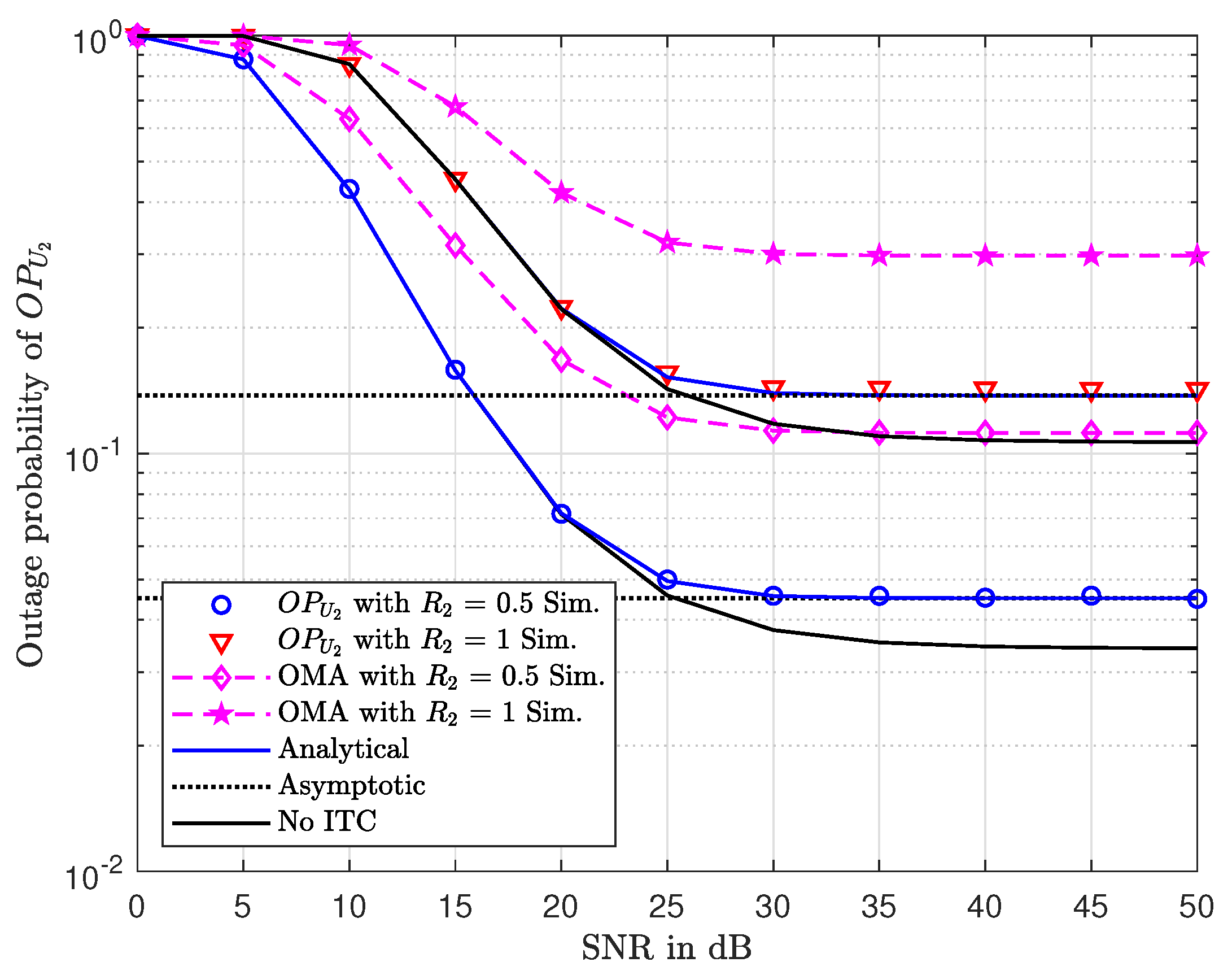
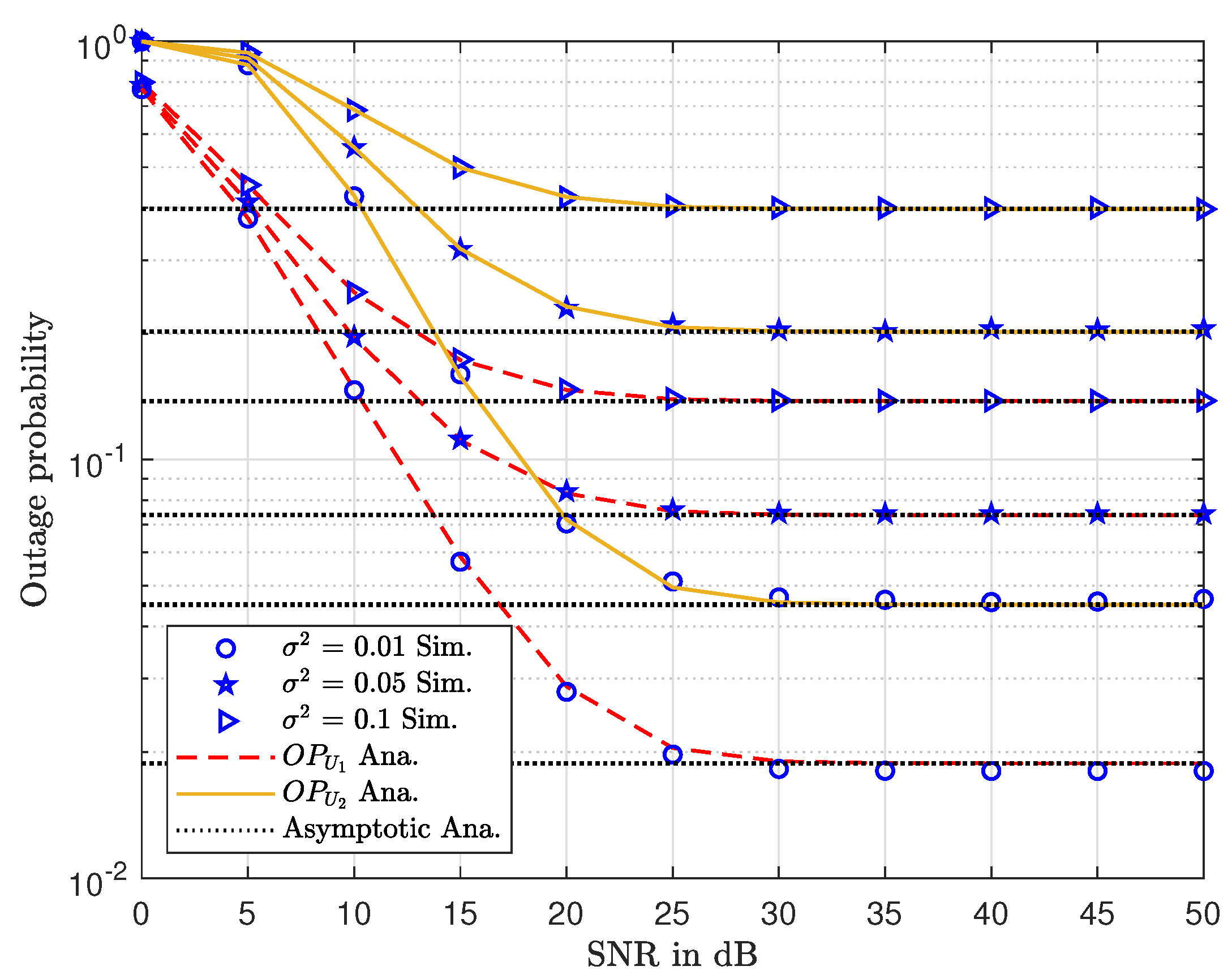
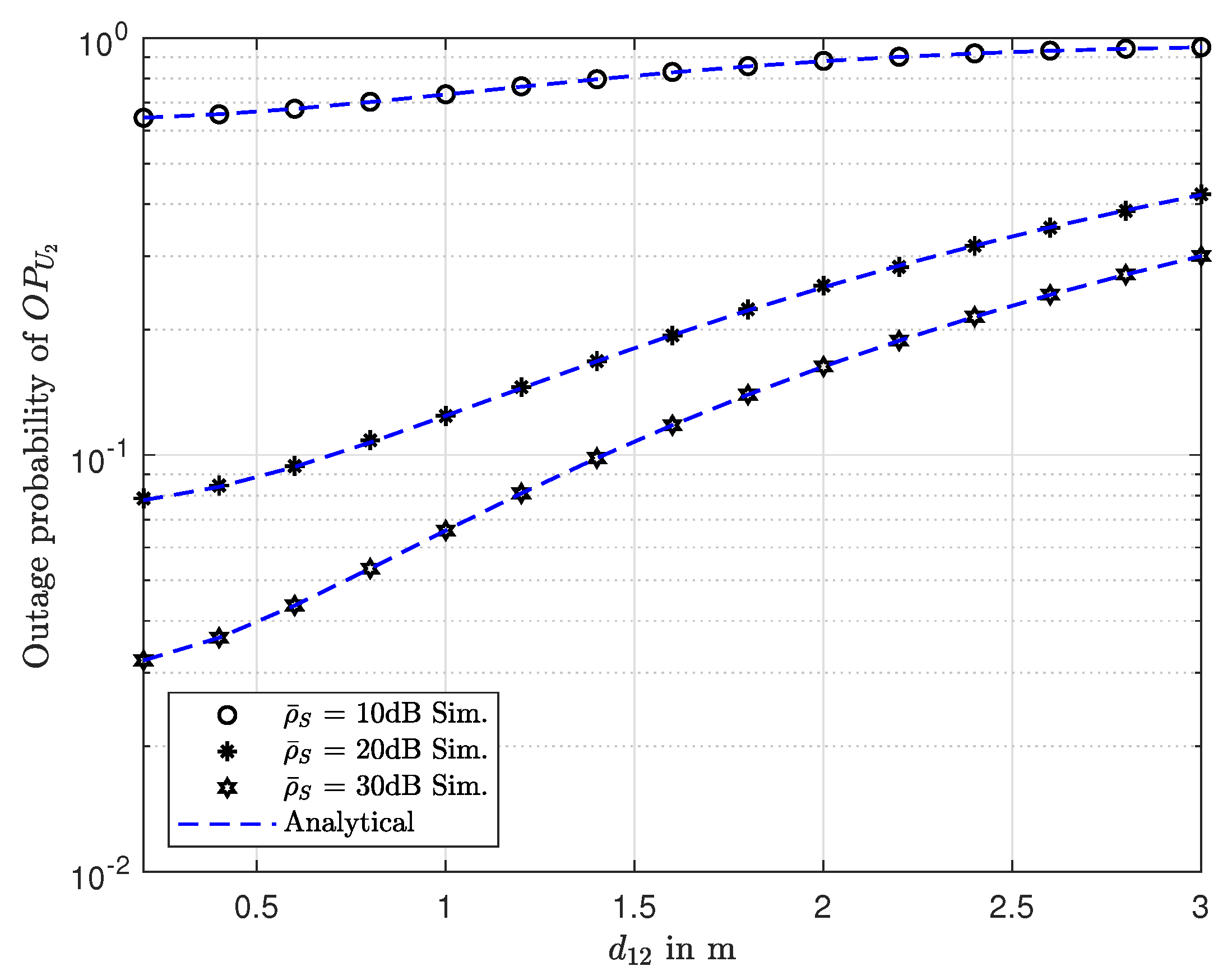
6. Numerical and Simulation Results

In this section, in order to verify mathematical analysis, it requires simulation and illustration for the proposed CR scheme under imperfect CSI. In this circumstance, the Rayleigh fading channel model is performed to model the wireless channels [11]. In addition, the path loss exponent parameter is set to 3. Moreover, we also simulate the linear harvesting model as intuitive indications shown in each figure. In this section, we set distances with unit m(meter) as d 1 = 1.2 , d 2 = 3 , d 12 = 1.8 , d S P = d 1 P = 1 , ξ = 2 , SNR related to interference ρ I = 25 dB, and the noise terms are σ 2 = σ 1 2 = σ 2 2 = σ 12 2 = 0.01 .
Figure 2 illustrates the outage probability of two secondary destinations, i.e., U 1 and U 2 as varying target rates versus transmit SNR at secondary source in three scenarios as indicated. As higher transmit SNR is required, outage performance will be improved significantly at the considered range of SNR from 30 dB to 50 dB. The asymptotic curves match with the analytical curves very well at high SNR. This output confirms exact approximate expressions of outage probability archived for two users. It is intuitively seen that no ITC case exhibits the lowest performance since no harmful interference from the PN exists. It can be seen that the performance gap of these cases with different data rates is small, and it exhibits acceptance performance for such NOMA with acceptable small value of target rate. In addition, Monte Carlo simulation results match with analytical results very well in whole range of SNR. However, it can be seen that a saturation situation happens as SNR is greater than 30 dB. These results confirmed that, with the low data rate requirements of the users, energy can be inherently harvested from the power beacon and successful data transmission can be perfectly processed. Powering energy from the power beacon is a reasonable solution for small devices that need an amount of power for their operation.
Figure 3 plots outage performance as compared to U 1 and U 2 . It can be seen clearly that at each value of CSI imperfection level, the outage probability of user U 1 is better than that of U 2 . It is also confirmed that a higher level of CSI imperfection contributes to worse outage behavior. An outage performance gap exists among two secondary users. The main reason is that different link and different power allocation factors are the main impacts related to such observation.
Node arrangement is a necessary concern in such CR networks in terms of outage performance as illustrated in Figure 4. We can compare three cases ρ ¯ S = , 10 , 20 , 30 dB in this plot. In this observation, ρ ¯ S = 30 dB indicated that the lowest outage probability can be obtained in the case of close distance between node U 1 and U 2 . Of course, when user U 2 is located very far from U 1 , a bad outage situation can occur.
Figure 5 clearly shows the impact of target rates on outage performance of U 1 , U 2 . The most important observation is that user U 2 approaches the worst case as it meets an outage event at γ 1 = γ 2 = 4 , S N R = 10 dB. The performance gap of two users can be seen clearly in the entire range of γ 1 , γ 2 . The main reason for this is that the probability to achieve high SNR is difficult. According to our observation, at a very low data rate, outage performance of U 1 is low.
The analysis to find the optimal power allocation factor is related to the performance of user U 2 . Therefore, optimal throughput of user U 2 can be verified as in Figure 6. More importantly, Equation (42) exhibits the optimal value of α and its exact point to raise maximal throughput. Such observation provides a way to achieve maximal throughput. The main reason for the appearance of a bump point is that the proposed system model combines NOMA and OMA schemes. As a result, when it does not allocate sufficient power to user 2 with respect to decoding the required signal, the OMA scheme is selected. It is worth noting that OMA does not depend on α and then a straight line occurred in the figure. In contrast, once α is large enough to select a NOMA scheme that is better than OMA, it is easy to see that the NOMA scheme exhibits its performance following the fluctuation of α and hence the bump point happens in the indicated figure.
The trend of throughput related to user U 2 in such a CR network versus power allocation factor α is illustrated in Figure 7 for two cases: R 1 = R 2 = 1.5 ( B P C U ) , R 1 = R 2 = 2 ( B P C U ) . The lower target rates assigned to two users result in higher throughput. This observation is consistent with results in outage performance. It is intuitive that higher SNR, i.e., S N R = 30 dB, provides higher throughput. The reason is that higher α means less power assigned for user U 2 , and hence throughput of U 2 will be decreased significantly.
Unlike the throughput performance trend reported in Figure 7, Figure 8 presents a performance gap in terms of throughput as comparing two cases R 1 = R 2 = 0.5 ( B P C U ) , R 1 = R 2 = 1 ( B P C U ) . It can be seen that throughput of user U 1 increases as it changes from R 1 = R 2 = 0.5 ( B P C U ) to R 1 = R 2 = 1 ( B P C U ) . Comparing these cases of CSI imperfection levels σ 2 = 0.01 , 0.05 , 0.1 , the throughput performance of two users is evaluated. By varying target rates R 1 = R 2 , it is exhibited that optimal throughput can be found by the numerical simulation method—for example, maximum throughput of user U 1 , i.e., T 1 = 0.83 at points of R 1 = R 2 = 1.3 , σ 2 = 0.05 while T 1 = 0.6 . As a result, such results are matched with previous experiments.
These illustrations confirm the role of how exact CSI in such CR network is, and it contributes to outage performance and throughput remarkably.
Figure 9 further confirms the role of design of multiple antennae assigned at the BS; improved outage performance can be observed as an increasing group of antennae serving users U i from M = H = 1 to M = H = 2 . Such result is an extended case with improved performance while having higher complexity as the design of BS.

7. Conclusions

In this paper, in order to keep operating together with an acceptable outage performance of the CR network, OMA/NOMA selection policy is required for fairness in NOMA satisfied. We studied how CSI imperfection makes crucial impacts on outage and throughput performance. The exact expressions of outage performance for two users were studied under a OMA/NOMA selection model. The impact of required data rates and level of CSI imperfection were jointly examined to achieve reasonable outage performance while satisfying fairness in the CR network considered. As they were the main results, these results on outage and throughput were considered to evaluate the challenges of CSI imperfection in the deployment of CR in the context of a NOMA scheme.

Author Contributions

D.-T.D. gave idea, designed the system model, checked the results and wrote the manuscript. While A.-T.L. performed the theoretical analysis, implemented the simulation and contributed to the manuscript preparation. B.M.L. was responsible for formulating the research issues and revised the paper.

Funding

This work was supported by the Basic Science Research Program through the National Research Foundation of Korea (NRF) funded by the Ministry of Education (Grant No. NRF-2017R1D1A1B03028350).

Conflicts of Interest

The authors declare no conflict of interest.

Appendix A

Proof of Proposition 1.
Next, we further examine the outage event at the BS for x 2 and it can be formulated by
Pr Q 0 = Pr ρ ¯ S h ^ 1 2 Θ ^ ρ ¯ S σ 1 2 + η + 1 , ρ ¯ S < ρ I h S P 2 + Pr ρ I h S P 2 h ^ 1 2 Θ ^ ρ I h S P 2 σ 1 2 + η + 1 , ρ ¯ S > ρ I h S P 2 ,
where ρ I = I t h N 0 ; then, it can be obtained as
Pr Q 0 = Pr h ^ 1 2 Θ ^ ρ ¯ S σ 1 2 + η + 1 ρ ¯ S , h S P 2 < ρ I ρ ¯ S B 1 + Pr h ^ 1 2 h S P 2 Θ ^ η + 1 + Θ ^ ρ I σ 1 2 ρ I , h S P 2 > ρ I ρ ¯ S B 2 .
Thus, B 1 can be calculated by
B 1 = 0 ρ I ρ ¯ S f h S P 2 y Θ ^ ρ ¯ S σ 1 2 + η + 1 ρ ¯ S f h ^ 1 2 z d y d z .
With the help of Equation (14), B 1 can be rewritten as
B 1 = e Θ ^ ρ ¯ S σ 1 2 + η + 1 λ 1 ρ ¯ S 1 e ρ I λ S P ρ ¯ S .
Similarly, B 2 is computed by
B 2 = ρ I ρ ¯ S f h S P 2 y Θ ^ y η + 1 + Θ ^ ρ I σ 1 2 ρ I f h 1 2 z d y d z .
Finally, B 2 can be calculated as
B 2 = λ 1 ρ I e λ 1 ρ I + λ S P Θ ^ η + 1 λ S P λ 1 ρ ¯ S Θ ^ σ 1 2 λ 1 λ 1 ρ I + λ S P Θ ^ η + 1 .
This completes the proof. □

Appendix B

Proof of Proposition 2.
In this case, Pr Q 0 can be rewritten as
Pr Q 0 = Pr ρ ¯ S h ^ 1 2 > Θ ^ ρ ¯ S σ 1 2 + η + 1 , ρ ¯ S < ρ I h S P 2 + Pr ρ I h S P 2 h ^ 1 2 > Θ ^ ρ I σ 1 2 + h S P 2 η + 1 h S P 2 , ρ ¯ S > ρ I h S P 2 .
First, we denote the first and second term of (A7) as C 1 and C 2 , respectively. Then, C 1 can be expressed as
C 1 = 0 ρ I ρ ¯ S f h S P 2 y Θ ^ ρ ¯ S σ 1 2 + η + 1 ρ ¯ S f h ^ 1 2 z d y d z .
With the help of Equations (49) and (50), it can be rewritten as
C 1 = e Θ ^ ρ ¯ S σ 1 2 + η + 1 λ 1 ρ ¯ S m = 1 M 1 Θ ^ ρ ¯ S σ 1 2 + η + 1 m Γ m + 1 ρ ¯ S λ 1 m 1 e ρ I λ S P ρ ¯ S .
Then, C 2 can be given as
C 2 = ρ I ρ ¯ S f h S P 2 y Θ ^ y η + 1 + Θ ^ ρ I σ 1 2 ρ I f h 1 2 z d y d z .
Thus, with the help of Equation (4). 337.2 and Equation (1). 111 in [32], the following can be obtained:
C 2 = m = 0 M 1 n = 0 m m n Θ ^ m ρ I λ 1 + λ S P Θ ^ η + 1 n 1 ρ I σ 1 2 m n Γ m + 1 ρ I λ 1 m n 1 η + 1 λ S P n e Θ ^ σ 1 2 λ 1 Γ n + 1 , ρ I λ 1 + λ S P Θ ^ η + 1 λ S P ρ ¯ S λ 1 .
This completes the proof. □

References

  1. Islam, S.R.; Avazov, N.; Dobre, O.A.; Kwak, K.S. Power-domain non-orthogonal multiple access (NOMA) in 5G systems: Potentials and challenges. IEEE Commun. Surv. Tutor. 2015, 2, 721–742. [Google Scholar] [CrossRef]
  2. Ding, Z.; Lei, X.; Karagiannidis, G.K.; Schober, R.; Yuan, J.; Bhargava, V.K. A survey on non-orthogonal multiple access for 5G networks: Research challenges and future trends. IEEE J. Sel. Areas Commun. 2017, 10, 2181–2195. [Google Scholar] [CrossRef]
  3. Nguyen, T.L.; Do, D.T. Exploiting Impacts of Intercell Interference on SWIPT-assisted Non-orthogonal Multiple Access. Wirel. Commun. Mob. Comput. 2018, 2018, 2525492. [Google Scholar] [CrossRef]
  4. Nguyen, X.X.; Do, D.T. Maximum Harvested Energy Policy in Full-Duplex Relaying Networks with SWIPT. Int. J. Commun. Syst. 2017, 30, e3359. [Google Scholar] [CrossRef]
  5. Do, D.T.; Nguyen, H.S.; Vozňák, M.; Nguyen, T.S. Wireless powered relaying networks under imperfect channel state information: System performance and optimal policy for instantaneous rate. Radioengineering 2017, 26, 869–877. [Google Scholar] [CrossRef]
  6. Nguyen, X.X.; Do, D.T. Optimal Power Allocation and Throughput Performance of Full-Duplex DF Relaying Networks with Wireless Power Transfer-Aware Channel. EURASIP J. Wirel. Commun. Netw. 2017, 2017, 152. [Google Scholar] [CrossRef]
  7. Nguyen, H.S.; Do, D.T.; Nguyen, T.S.; Voznak, M. Exploiting hybrid time switching-based and power splitting-based relaying protocol in wireless powered communication networks with outdated channel state information. Automatika 2017, 58, 111–118. [Google Scholar] [CrossRef] [Green Version]
  8. Nguyen, T.N.; Tran, M.; Tran, P.T.; Tin, P.T.; Nguyen, T.L.; Ha, D.H.; Voznak, M. On the Performance of Power Splitting Energy Harvested Wireless Full-Duplex Relaying Network with Imperfect CSI over Dissimilar Channels. Secur. Commun. Netw. 2018, 2018, 6036087. [Google Scholar] [CrossRef]
  9. Nguyen, T.; Tran Tin, P.; Ha, D.; Voznak, M.; Tran, P.; Tran, M.; Nguyen, T.L. Hybrid TSR–PSR Alternate Energy Harvesting Relay Network over Rician Fading Channels: Outage Probability and SER Analysis. Sensors 2018, 18, 3839. [Google Scholar] [CrossRef]
  10. Nguyen, T.N.; Tran, P.T.; Vozňák, M. Power-splitting-based energy harvesting protocol for wireless powered communication networks with a bidirectional relay. Int. J. Commun. Syst. 2018, 31, e3721. [Google Scholar] [CrossRef]
  11. Do, D.T.; Le, C.B. Application of NOMA in Wireless System with Wireless Power Transfer Scheme: Outage and Ergodic Capacity Performance Analysis. Sensors 2018, 18, 3501. [Google Scholar] [CrossRef] [PubMed]
  12. Tsinos, C.G.; Berberidis, K. Decentralized Adaptive Eigenvalue-Based Spectrum Sensing for Multiantenna Cognitive Radio Systems. IEEE Trans. Wirel. Commun. 2015, 14, 1703–1715. [Google Scholar] [CrossRef]
  13. Gao, F.; Zhang, R.; Liang, Y.C.; Wang, X. Design of Learning-Based MIMO Cognitive Radio Systems. IEEE Trans. Veh. Technol. 2010, 59, 1707–1720. [Google Scholar] [Green Version]
  14. Zhang, H.; Jiang, C.; Mao, X.; Chen, H.H. Interference-limited resource optimization in cognitive femtocells with fairness and imperfect spectrum sensing. IEEE Trans. Veh. Technol. 2016, 65, 1761–1771. [Google Scholar] [CrossRef]
  15. Zhang, H.; Nie, Y.; Cheng, J.; Leung, V.C.; Nallanathan, A. Sensing time optimization and power control for energy efficient cognitive small cell with imperfect hybrid spectrum sensing. IEEE Trans. Wirel. Commun. 2017, 16, 730–743. [Google Scholar] [CrossRef]
  16. Nam, P.M.; Do, D.T.; Tung, N.T.; Tin, P.T. Energy harvesting assisted cognitive radio: Random location-based transceivers scheme and performance analysis. Telecommun. Syst. 2018, 67, 123–132. [Google Scholar] [CrossRef]
  17. Kumar, B.; Prakriya, S. Performance of adaptive link selection with buffer-aided relays in underlay cognitive networks. IEEE Trans. Veh. Technol. 2018, 67, 1492–1509. [Google Scholar] [CrossRef]
  18. Tsinos, C.G.; Berberidis, K. Blind Opportunistic Interference Alignment in MIMO Cognitive Radio Systems. IEEE J. Emerg. Sel. Top. Circuits Syst. 2013, 3, 626–639. [Google Scholar] [CrossRef]
  19. Zhang, R. On peak versus average interference power constraints for protecting primary users in cognitive radio networks. IEEE Trans. Wirel. Commun. 2009, 8, 2112–2120. [Google Scholar] [CrossRef]
  20. Liu, Y.; Ding, Z.; Elkashlan, M.; Yuan, J. Non-orthogonal multiple access in large-scale underlay cognitive radio networks. IEEE Trans. Veh. Technol. 2016, 65, 10152–10157. [Google Scholar] [CrossRef]
  21. Lv, L.; Chen, J.; Ni, Q.; Ding, Z. Design of cooperative nonorthogonal multicast cogntive radio multiple access for 5G systems: User scheduling and performance analysis. IEEE Trans. Commun. 2017, 65, 2641–2656. [Google Scholar] [CrossRef]
  22. Lv, L.; Ni, Q.; Ding, Z.; Chen, J. Application of non-orthogonal multiple access in cooperative spectrum-sharing networks over Nakagami-m fading channels. IEEE Trans. Veh. Technol. 2017, 66, 5506–5511. [Google Scholar] [CrossRef]
  23. Do, D.T.; Vaezi, M.; Nguyen, T.L. Wireless Powered Cooperative Relaying Using NOMA with Imperfect CSI. In Proceedings of the 2018 IEEE Globecom Workshops (GC Wkshps), Abu Dhabi, UAE, 9–13 December 2018; pp. 1–6. [Google Scholar]
  24. Cui, J.; Ding, Z.; Fan, P. Outage Probability Constrained MIMO-NOMA Designs Under Imperfect CSI. IEEE Trans. Wirel. Commun. 2018, 17, 8239–8255. [Google Scholar] [CrossRef]
  25. Fang, F.; Zhang, H.; Cheng, J.; Roy, S.; Leung, V.C. Joint User Scheduling and Power Allocation Optimization for Energy-Efficient NOMA Systems With Imperfect CSI. IEEE J. Sel. Areas Commun. 2017, 35, 2874–2885. [Google Scholar] [CrossRef]
  26. Arzykulov, S.; Tsiftsis, T.A.; Nauryzbayev, G.; Abdallah, M. Outage Performance of Cooperative Underlay CR-NOMA With Imperfect CSI. IEEE Commun. Lett. 2019, 23, 176–179. [Google Scholar] [CrossRef]
  27. Zamani, M.R.; Eslami, M.; Khorramizadeh, M.; Ding, Z. Energy-Efficient Power Allocation for NOMA with Imperfect CSI. IEEE Trans. Veh. Technol. 2019, 68, 1009–1013. [Google Scholar] [CrossRef]
  28. Song, X.; Dong, L.; Wang, J.; Qin, L.; Han, X. Energy Efficient Power Allocation for Downlink NOMA Heterogeneous Networks with Imperfect CSI. IEEE Access 2019, 7, 39329–39340. [Google Scholar] [CrossRef]
  29. Janghel, K.; Prakriya, S. Performance of Adaptive OMA/Cooperative-NOMA Scheme with User Selection. IEEE Commun. Lett. 2018, 22, 2092–2095. [Google Scholar] [CrossRef]
  30. Nauryzbayev, G.; Arzykulov, S.; Tsiftsis, T.A.; Abdallah, M. Performance of Cooperative Underlay CR-NOMA Networks over Nakagami-m Channels. In Proceedings of the 2018 IEEE International Conference on Communications Workshops (ICC Workshops), Kansas City, MO, USA, 20–24 May 2018; pp. 1–6. [Google Scholar]
  31. Xinh, N.X.; Do, D.T. An adaptive-harvest-then-transmit protocol for wireless powered communications: Multiple antennae system and performance analysis. KSII Trans. Internet Inf. Syst. 2017, 11, 1889–1910. [Google Scholar]
  32. Zwillinger, D. Table of Integrals, Series, and Products, 7th ed.; Academic Press: Cambridge, MA, USA, 2007. [Google Scholar]
Figure 1. System model of cognitive radio(CR) and section scheme of OMA/non-orthogonal multiple access(NOMA).
Electronics 08 00819 g001
Figure 2. Outage probability of O P U 2 vs. SNR with varying R 2 .
Electronics 08 00819 g002
Figure 3. Outage probability of two users vs. SNR with a varying level of CSI imperfection σ with R 1 = R 2 = 0 . 5 ( B P C U ) .
Electronics 08 00819 g003
Figure 4. Outage probability of O P U 2 vs. distance d 12 with varying ρ ¯ S with R 2 = 1 .
Electronics 08 00819 g004
Figure 5. Outage probability of two users vs. target rates with SNR = 10, 20 dB.
Electronics 08 00819 g005
Figure 6. Throughput of user U 2 vs. α .
Electronics 08 00819 g006
Figure 7. Throughput of U 2 vs. the target rate R 1 = R 2 .
Electronics 08 00819 g007
Figure 8. Throughput of system vs. the target rate R 1 = R 2 .
Electronics 08 00819 g008
Figure 9. Outage probability of U 1 and U 1 vs. number of antenna M = H .
Electronics 08 00819 g009

