Article

Continuous and Stable Cross-Eye Jamming via a Circular Retrodirective Array

1
College of Electronic Science and Technology, National University of Defense Technology, Changsha 410073, China
2
School of Electronic and Communication Engineering, Sun Yat-sen University, Shenzhen 518107, China
3
Beijing Huahang Radio Measurement Institute, Beijing 100013, China
*
Authors to whom correspondence should be addressed.
Electronics 2019, 8(7), 806; https://doi.org/10.3390/electronics8070806
Submission received: 27 May 2019 / Revised: 15 July 2019 / Accepted: 17 July 2019 / Published: 19 July 2019
(This article belongs to the Section Microwave and Wireless Communications)

Abstract

:
Cross-eye jamming is an angular deception jamming technique against monopulse radar. Multiple-element retrodirective cross-eye jamming (MRCJ) as an improved method, uses a retrodirective antenna array with multiple antenna elements in a cross-eye jammer and can obtain better jamming performance. However, the practical MRCJ system employing a linear antenna array becomes ineffective when the threat radar appears in the antenna array’s end-fire direction. To meet multiple threats from different directions and provide continuous jamming, MRCJ employing a circular antenna array (C-MRCJ) is proposed after defining the modulation direction of system parameters. Optimal configuration of C-MRCJ providing stable jamming performance is discussed. The number of the jammer loops is analyzed under considerable jamming performance and moderate hardware cost.

1. Introduction

Cross-eye jamming is an electronic countermeasure (ECM) technique which deceives the monopulse radar with a significant angular error. Inspired by the radar glint phenomenon, cross-eye jamming was proposed in the 1950s and also called artificial glint jamming [1,2,3]. As an effective jamming technique against monopulse radar, cross-eye jamming has remained of interest to researchers in the field of electronic warfare. In the past ten years, the analyses of the cross-eye jamming with retrodirective implementation, as shown in Figure 1, were presented in [4,5,6]. It is widely believed that the retrodirective implementation is the right way to build a practical cross-eye jamming system. The requirements of the tolerance and the jammer-to-signal ratio (JSR) for a retrodirective cross-eye jammer were discussed in [7,8,9]. The performance of a retrodirective cross-eye jamming system can induce an angular error into monopulse radar that even breaks the radar’s lock.
However, the high JSR and strict tolerance requirements limit the realization of a two-element retrodirective cross-eye jamming (TRCJ) system [7,8,9,10]. One feasible way to help overcome the above limitations is providing more degrees of freedom in a jammer which can control the desired field pattern better [11]. Herein, multiple amplitude gains and phase shifts as additional degrees of freedom were used, and multiple-element cross-eye jamming (MRCJ) was proposed in [12]. However, the analysis associated with MCJ did not take the retrodirective implementation into account and, thus, had limited practicality [4,5]. Considering the retrodirective implementation, multiple-element retrodirective cross-eye jamming (MRCJ) was researched [13,14,15,16,17,18,19]. Previous studies in [13,14] indicated that MRCJ employing a linear retrodirective array, notation L-MRCJ for convenience, has a superior performance due to additional degrees of freedom, and showed that L-MRCJ can reduce both the JSR requirements and the tolerance sensitivity.
Unfortunately, L-MRCJ will be ineffective when the threat radar appears in the end-fire direction of the jammer antenna array. It is because the angular separation of the jammer antenna array approaches zero. Although the wide-beamwidth antenna elements are used to construct L-MRCJ system for covering a wide angle range, there are still angular areas where the jammer is ineffective. To offer protection for the ineffective area, a cross-eye jammer mounted on a fighter is often used in combination with a towed decoy [20]. Thus, L-MRCJ cannot always induce continuous angular error in the threat radar.
To provide effective protection in whichever direction the potential threat signal transmits, the idea of using multiple independent jammer loops to cover a 360 angular region was mentioned naturally by Neri in [21], where a different single jammer loop is chosen to confront the threat from different directions. However, this “switch” approach providing continuous jamming with a single jammer loop gives up the superiority of additional degrees of freedom and still suffers from the limitations associated with a two-element cross-eye jammer.
MRCJ employing a circular retrodirective array, notation C-MRCJ, will be investigated in this paper. Unlike the “switch” approach, C-MRCJ uses multiple jammer loops together against the threat radar in one direction. The C-MRCJ has the advantage over L-MRCJ by employing multiple rotational angles from its jammer configuration, which makes C-MRCJ have the potential to deal with the threat from various incident angles. However, C-MRCJ can also be ineffective since the angular error induced by C-MRCJ can still be zero in certain directions. To provide continuous cross-eye jamming, we further propose a modified C-MRCJ based on a priori information of Direction Of Arrival (DOA) of radar waves by defining the modulation direction (MD) of jammer loops. Modified C-MRCJ changes the MDs of jammer loops according to the DOA information provided by a missile approach warner (MAW) or other radar signal detectors [22,23,24], in order to make multiple jammer loops superimpose their contributions to the monopulse ratio. Thus, the angular error induced by modified C-MRCJ will never be zero within the coverage of 360 . Synchronously, modified C-MRCJ has the potential to achieve stable jamming performance with special configuration. Continuous and stable jamming performance can produce a fixed and stable apparent target away from the platform, which is desirable for a jammer mounted on a moving and rotating platform in practical operations.
As far as we known, the literature [25] had proposed a similar jamming configuration consisting of two jammer loops to address the problem brought by the rotating platform. Its contributions is that it gave a basis analysis of MRCJ employing a rectangular array. Actually, the rotating cross-eye jammer consisting of two jammer loops is a special and the simplest scenario of C-MRCJ, considering the fact that a rectangular array can always be simplified by a circular array. On the basis of the analysis in [25], this paper further extends the rectangular array to the circular array and proposes C-MRCJ. The results will indicate that a rectangular array employed by the MRCJ system is not the best array configuration when considering jamming performance.
Overcoming the limitations of existing literature, this paper gives the major contributions to the area of cross-eye jamming as follows:
  • MRCJ with a circular antenna array is proposed which has the potential to deal with the radar threat in any likely direction.
  • The modulation direction of the jammer loop is defined which makes the jammer have the ability to provide continuous jamming performance.
  • The array configuration with uniform-spacing angular separation is proved to be the optimal configuration for modified C-MRCJ to achieve stable jamming performance.
  • Six antenna elements are advised for modified C-MRCJ in consideration of considerable jamming performance and moderate hardware cost.
The mathematical expression of the monopulse-indicated angle under the action of C-MRCJ is derived in Section 2. Defining the MD of the jammer loop, the modified C-MRCJ providing continuous jamming performance is proposed in Section 2. The jamming performance of C-MRCJ compared to TRCJ and L-MRCJ is discussed in Section 3. Furthermore, the ability of modified C-MRCJ in achieving continuous and stable jamming performance and the choice of the number of jammer loops are demonstrated in Section 3. In Section 4, brief conclusions and future research directions are presented.
For readers’ convenience, the notations used in the rest of the paper are listed partly here. r is the range between the radar and the jammer, d p is the distance between the two antennas of monopulse radar, θ r is the rotational angle to the platform measured from the radar’s boresight, d c is the baseline length of the jammer loop or the diameter of the circular array, θ c n is the rotational angle of the nth jammer loop, θ n is the half angular separation of the nth jammer loop, α n is the angular separation measured from the nth jammer loop to the ( n + 1 ) th jammer loop, S J and D J are respectively the total sum-channel and difference-channel returns received by the radar, M J is the monopulse ratio which is used to compute the monopulse-indicated angel θ i , G c is the cross-eye gain of cross-eye jamming. The other notations will be given in appropriate locations in the paper.

2. Theoretical Analysis of C-MRCJ

2.1. Jamming Scenario

The performance analysis of C-MRCJ is performed where a phase-comparison monopulse radar is employed as shown in Figure 2. Only a phase-comparison monopulse radar is taken into account since the same conclusions can be obtained by using either the phase-comparison monopulse radar or the amplitude-comparison monopulse radar [26]. The radar consists of two antenna elements denoted by circles. The circular retrodirective array of C-MRCJ comprises N antenna elements (denoted by the crosses) and N / 2 jammer loops. The construction of each jammer loop is shown in Figure 1. A different jammer loop has same baseline length and different rotational angle. The platform protected by C-MRCJ is located at the centre of the circular array (denoted by the solid square), and the position of the apparent target is denoted by the hollow square.
According to the jamming geometry, the half angular separation θ n of the nth jammer loop can be given by
tan ( θ n ) d c cos θ c n 2 r .
Given the fact that θ n is very small under the assumption that d c is much smaller than r, the expression in (1) can be simplified to
θ n d c cos θ c n 2 r .

2.2. Cross-Eye Gain of C-MRCJ

For the nth jammer loop, the angles to the top jammer antenna (above the x axis in Figure 2) and to the bottom jammer antenna (below the x axis) from the threat radar are θ r + θ n and θ r θ n , respectively. The normalized sum-channel and difference-channel gains of the monopulse radar in the directions of θ r ± θ n are, respectively, given from [4,13] as
S t , d = cos β d p 2 sin θ r ± θ n P r θ r ± θ n
and
D t , d = j sin β d p 2 sin θ r ± θ n P r θ r ± θ n
where β is the free-space phase constant and P r ( θ r ± θ n ) are the gains of the radar antennas in the directions of θ r ± θ n .
For C-MRCJ, there are differences between different jammer loops due to different transmission paths and circuit elements. The differences between the jammer loops affect the jamming performance of MRCJ significantly [16,17,18]. We use the factor C n = c n e j φ n to account for the jammer loop parameters where c n is the attenuation and φ n is the phase shift.
We denote an amplitude gain and a phase shift between the two directions through the nth jammer loop by a n and ϕ n , respectively. The modulation direction (MD) is defined as the direction in which the system parameters A n = a n e j ϕ n are modulated. As shown in Figure 1, the MD of the jammer loop is from antenna “A” to antenna “B”. Furthermore, we define the forward and reverse MD as following: if the antenna “A” is the top antenna element in Figure 2, the MD is forward, whereas the MD is reverse. When the platform rotates, the MD of the nth jammer loop could be either forward or reverse that is determined by the position of antenna “A”.
For the forward MD case, the sum-channel and the difference-channel returns of the nth jammer loop received by the monopulse radar are, respectively, given by
S J n = 1 2 P n ( 1 + A n ) cos 2 k s n + cos 2 k c n
and
D J n = j 1 2 P n ( 1 + A n ) sin 2 k s n + ( 1 A n ) sin 2 k c n
with
k s n = β d p 2 sin θ r cos θ n
k c n = β d p 2 cos θ r sin θ n
and
P n = P r θ r θ n P c θ c n θ n P r θ r + θ n P c θ c n + θ n
where P c denotes the antenna gain of the jammer.
For the reverse MD case, the sum-channel and the difference-channel returns of the nth jammer loop received by the monopulse radar are, respectively, given by
S J n = 1 2 P n ( A n + 1 ) cos 2 k s n + cos 2 k c n
and
D J n = j 1 2 P n ( A n + 1 ) sin 2 k s n + ( A n 1 ) sin 2 k c n .
By denoting the MD by I n , the total sum-channel and the difference-channel returns are, respectively, given by
S J = 1 2 n = 1 N / 2 C n P n ( 1 + A n ) cos ( 2 k s n ) + cos ( 2 k c n )
and
D J = j 1 2 n = 1 N / 2 C n P n ( 1 + A n ) sin ( 2 k s n ) + I n ( 1 A n ) sin ( 2 k c n )
with the upper and lower signs of I n = ± 1 denoting the forward and reverse MD, respectively.
Normalizing the total difference-channel return D J by the total sum-channel return S J gives the monopulse ratio of C-MRCJ as
M J = D J S J
n = 1 N / 2 C n P n ( 1 + A n ) sin ( 2 k s n ) + I n ( 1 A n ) sin ( 2 k c n ) n = 1 N / 2 C n P n ( 1 + A n ) [ cos ( 2 k s n ) + cos ( 2 k c n ) ]
where ( z ) and ( z ) denote the imaginary and real part of the signal z, respectively.
Under the assumption that θ n is very small, the angles θ r ± θ n and θ c n ± θ n can be approximated to θ r and θ c n , respectively. Thus, the pattern in (9) can be approximated to
P n P r 2 θ r P c 2 θ c n .
Meanwhile, the terms in (7) and (8) can also be approximated to
k s n β d p 2 sin ( θ r )
= k
k c n β d p 2 cos ( θ r ) θ n
β d p 2 cos ( θ r ) d c 2 r cos θ c n
= k c cos θ c n
where the result in (2) was substituted into (19), and the notations k and k c were used to simplify the results in (17) and (20), and k c is given by
k c = β d p 2 cos ( θ r ) d c 2 r .
Hence, the monopulse ratio in (15) can be simplified to
M J tan k + 2 k c cos ( 2 k ) + 1 n = 1 N / 2 C n P c 2 θ c n I n 1 A n cos θ c n n = 1 N / 2 C n P c 2 θ c n 1 + A n
where
tan k = sin 2 k cos 2 k + 1
cos ( 2 k c n ) 1
sin ( 2 k c n ) 2 k c n
were used.
We define the term in (23)
G c = n = 1 N / 2 C n P c 2 θ c n I n 1 A n cos θ c n n = 1 N / 2 C n P c 2 θ c n 1 + A n
as the cross-eye gain of C-MRCJ.
It can be found in (27) that the pattern of the jammer antenna element P c θ c n is contained in the expression of the cross-eye gain, which means that the value of cross-eye gain of C-MRCJ varies with the pattern of the jammer antenna. It is undesirable, because the nulls of the pattern will cause the cross-eye gain to be zero when the jammer antennas rotate. To overcome this problem, omnidirectional antenna or phased-array antenna could be a feasible and beneficial choice. Considering the high power requirements for the omnidirectional antenna, the phased-array antenna with adaptive beam-forming algorithm is advised to be a better choice. The adaptive beam-forming algorithm can make the pattern of the jammer antenna be identical in the direction of the threat radar, which means that P c θ c n is constant.
Therefore, the cross-eye gain of C-MRCJ with identical antenna gain in the direction of θ c n is given by
G c = n = 1 N / 2 C n I n 1 A n cos θ c n n = 1 N / 2 C n 1 + A n .
Substituting (28) into (23) gives
M J tan k + 2 k c cos ( 2 k ) + 1 G c .
The monopulse ratio under the action of C-MRCJ consists of two terms on the right hand of (29). The first term acts as a beacon giving the right angular information of the platform, while the second term induces the wrong angular information into the monopulse radar. The angular error term consists of four factors: the physical geometry, the system parameters, the MD and the rotational angles of the jammer loops.
The monopulse-indicated angle including the right and wrong angle information can be computed from the monopulse ratio
M J = tan β d p 2 sin ( θ i )
where θ i is the monopulse-indicated angle.

2.3. Continuous Jamming by Modifying MD

The angular error induced by C-MRCJ will be zero in specified directions where the radar being jammed appears, which is similar to L-MRCJ. This is because that the term n = 1 N / 2 C n I n 1 A n cos θ c n in (28) becomes zero under the combined effect of the factors including the system parameters, the MDs and the rotational angles of the jammer loops. Hence, C-MRCJ cannot be always effective.
A C-MRCJ system with six antenna elements and three jammer loops shown in Figure 3 is employed to explain the above conclusion further. We denote the jammer loop constituted by antennas n and N / 2 + n as jammer loop n. For example, the jammer loop consisting of antennas 1 and 4 is jammer loop 1. According to the definition of the forward and reverse MD and the DOA information provided by MAW, the MDs of jammer loop 1 and 2 are forward, while the MD of jammer loop 3 is reverse. The reverse MD has the opposite effect comparing to the forward MD, resulting to the cancellation of the difference-channel return from the jammer loops with opposite MDs, even causing the total difference-channel to return to zero when the radar appears in a specified direction. Hence, the angular error induced by C-MRCJ can be zero.
To induce continuous angular error without zero into the monopulse radar, modified C-MRCJ is proposed which modifies the MDs of jammer loops according to the DOA information adaptively. For example, when the radar wave arrives at the angular region between antenna 5 and 6 as shown in Figure 3, we change the MD of jammer loop 3 from the reverse direction to the forward direction. As a result, all jammer loops provide the same contribution to the total difference-channel return received by the radar being jammed. The angular error will never be zero in whichever direction the radar signal transmits. Figure 4 gives the flow diagram of signal processing of modified C-MRCJ.
The process of MD modification can be done instantaneously by switching the directions of signal transmission through the circulators as shown in Figure 5. Four switchers are needed for a single jammer loop. Then, the time delay induced by modifying MD is very short to ensure the timeliness of the cross-eye jammer.
Furthermore, the rotational angles θ c n of jammer loops have an effect on the cross-eye gain in (28). Hence, choosing suitable angular separations between the jammer loops can introduce stable jamming performance which possesses the largest mean and the smallest variance of angular error. This character of modified C-MRCJ providing continuous and stable jamming performance will produce a fixed and stable apparent target away from the platform, which is important in practical operations.

3. Results and Discussion

Considering the large number of system parameters of C-MRCJ with N antenna elements, two circular array configurations with different angular separations between the jammer loops are employed by C-MRCJ system as shown in Figure 6. The angular separations between jammer loops are shown in the figure. The base-lengths of the jammer loops of these two configurations are d c . For comparison, we consider a L-MRCJ system with six antenna elements as shown in Figure 7. We denote the jammer loop of L-MRCJ constituted by antennas n and N n as jammer loop n. For example, antennas 1 and 6 comprise the jammer loop 1 of L-MRCJ as shown in Figure 7.
The values of the scenario parameters for simulation are given as follows:
  • the radar carrier frequency is 9 GHz,
  • the radar antenna aperture is 2.54 λ ,
  • the jammer range is 1 km,
  • the jammer base-length is 10 m.
We assume that the path-length differences have been well compensated for and assume that C n = 1 .

3.1. Angular Error Induced by C-MRCJ

Assume the rotational angle of jammer loop 1 is 0 for both L-MRCJ and C-MRCJ. The rotational angles of jammer loop 2 and 3 of configuration 1 of C-MRCJ (C-MRCJ 1) are 15 and 165 respectively, and those of configuration 2 of C-MRCJ (C-MRCJ 2) are 60 and 120 respectively.
Monopulse-indicated angles of different jammer array configurations are plotted in Figure 8 when the system parameters A n are described in the figure caption.
An obvious conclusion which arises from Figure 8 is that the curves of the monopulse-indicated angle for the four configurations considered have no zeros in the radar 3 dB beamwidth. It means that the monopulse radar cannot lock its target under the action of either TRCJ or MRCJ. In other words, C-MRCJ has the same potential as TRCJ and L-MRCJ to break the lock of a monopulse radar.
The monopulse-indicated angle can be regarded as the angular error when the radar angle is zero. Figure 8 demonstrates that either C-MRCJ or L-MRCJ can induces much larger angular error into the monopulse radar than TRCJ for the specified system parameters. The superiority of MRCJ to obtain the larger angular errors benefits form the more degrees of freedom which allows the system parameters to be endowed with appropriate values to obtain larger cross-eye gain.
Comparing the curves of C-MRCJ with the curve of L-MRCJ in Figure 8 gives the conclusion that there is no superiority for C-MRCJ in the aspect of inducing angular error compared to L-MRCJ. C-MRCJ can obtain either a larger or smaller angular error compared to L-MRCJ which is determined by the sum of the base-lengths of the inner jammer loops (except the jammer loop 1) against the radar’s boresight when the system parameters are the same. For example, the base-length sum of inner jammer loops of C-MRCJ 1 against the radar’s boresight is 0.97 d c which is larger than L-MRCJ, and the base-length sum of C-MRCJ 2 is 0.5 d c which is smaller than L-MRCJ. Actually, the difference between C-MRCJ and L-MRCJ is that the factor affecting the value of cross-eye gain is not the same, which is the ratio of base-lengths of jammer loops for L-MRCJ and is the angular separations between the jammer loops for C-MRCJ.

3.2. Continuous Jamming Provided by Modified C-MRCJ

We firstly investigate the variation of the angular error induced by C-MRCJ without the use of MD modification. We assume that the radar angle is zero, i.e., θ r = 0 . Thus, the monopulse-indicated angle will indicate the value of angular error when θ r = 0 . The rotational angle of jammer loop 1 is limited in ( 180 , 180 ) . The monopulse-indicated angles of L-MRCJ and C-MRCJ for different system parameters A n are plotted in Figure 9.
It can be observed from Figure 9 that the monopulse-indicated angle of L-MRCJ will be zero when the rotational angle of jammer loop 1 is ± 90 . This means that L-MRCJ will be ineffective when the radar being jammed appears in the end-fire direction of jammer antenna array.
However, C-MRCJ can also induce a monopulse-indicated angle of zero in specified angles as shown in Figure 9. Taking C-MRCJ 2 as an example, the monopulse-indicated angle will be zero when the rotational angle of jammer loop 1 is 150 or 30 as shown in Figure 9a. Comparisons between the results in Figure 9a,b demonstrate that the changes of system parameters and angular separations between the jammer loops only change the value of the angular error and the specified angles making C-MRCJ ineffective.
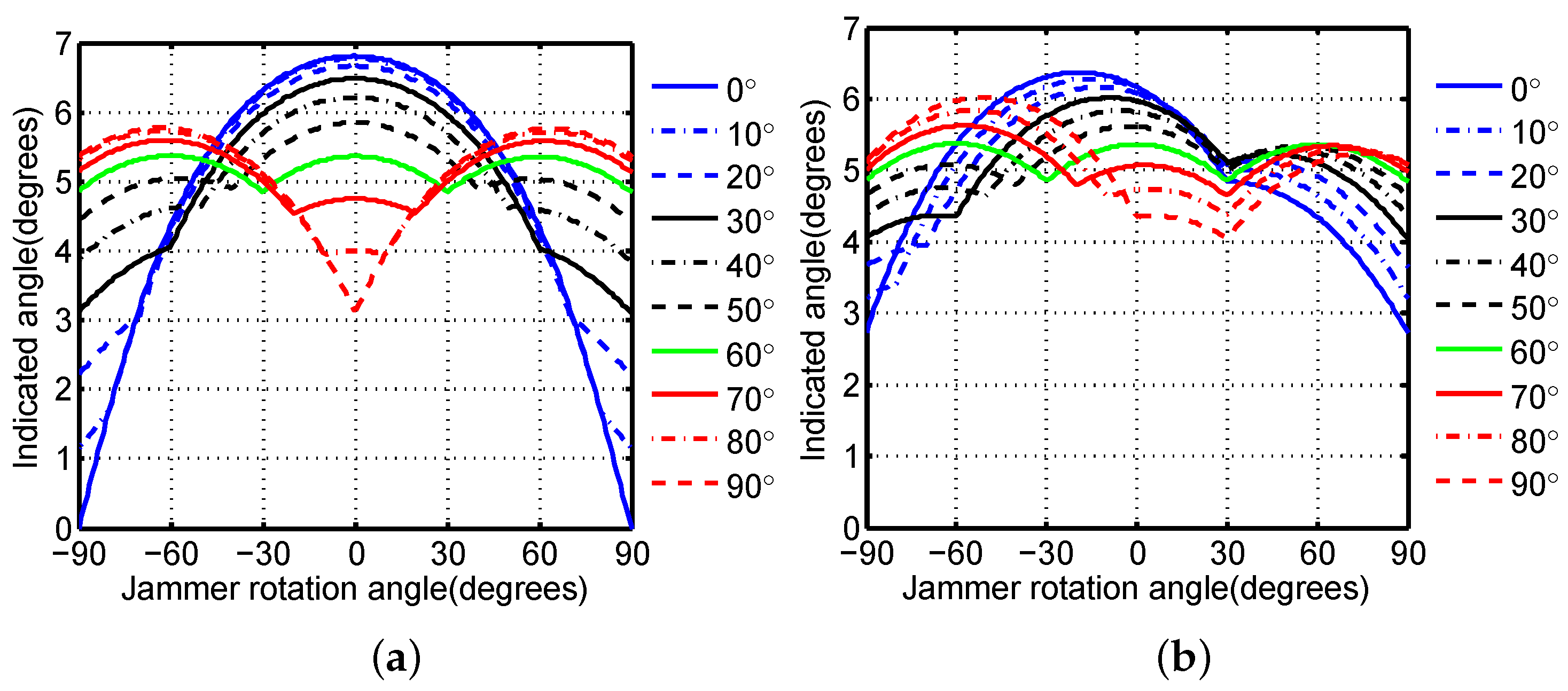
We secondly investigate the continuous jamming performance achieved by the modified C-MRCJ with modified MD. To produce a continuous apparent target above the rotating platform, the modification details of MDs according to DOA information for modified C-MRCJ are given in Table 1. Substituting the modified MDs into (28)–(30) gives the monopulse-indicated angle of modified C-MRCJ, which is plotted in Figure 10 for different system parameters A n .
An important conclusion from Figure 10 is that the monopulse-indicated angle of modified C-MRCJ never becomes zero wherever the radar was being jammed, while L-MRCJ cannot. This means that modified C-MRCJ can provide continuous angular error within the coverage of 360 . The continuous jamming performance is important for a cross-eye jammer mounted on a rotating platform, which makes the jammer avoid becoming a beacon. Furthermore, modified C-MRCJ has the ability to fix the apparent target despite the direction the radar appears. The modification details given in Table 1 limit the apparent target locating above the platform.
Another conclusion from comparisons between Figure 10a,b is that the system parameters A n do not affect the shape of the monopulse-indicated angle curves, but affect the value of the monopulse-indicated angle. This conclusion is useful for building a practical C-MRCJ system, the system parameters and the MD, respectively, take charge of the value of the induced angular error and the ability of continuous jamming.

3.3. Stable Jamming Provided by Modified C-MRCJ

Besides providing continuous jamming performance, modified C-MRCJ has the potential to achieve stable jamming performance. The ability to produce a stable apparent target is desirable for a cross-eye jammer mounted on a rotating platform. Figure 10 illustrates that the variation of the monopulse-indicated angle of C-MRCJ 2 is much smaller than C-MRCJ 1. Hence, C-MRCJ 2 with uniform-spacing angular separation is a better option than C-MRCJ 1 because it allows the jammer to provide a stable angular error over the coverage of 360 .
However, only two configurations of C-MRCJ are considered in Figure 10. To explore the optimal configuration of modified C-MRCJ pursuing the stablest jamming performance, we consider the following two cases of values which include all configurations with one angular separation is 60 :
  • Symmetrical case: α 1 = α 3 , α 2 = 180 α 1 α 3 , α 1 and α 3 vary from 0 to 90 with the step of 10 ;
  • Asymmetrical case: α 1 α 3 , α 2 = 180 α 1 α 3 , α 1 = 60 , α 3 varies from 0 to 90 with the step of 10 .
The monopulse-indicated angles for the above two cases are plotted in Figure 11. It can be observed that the configuration α 1 = α 2 = α 3 = 60 induces the stablest angular error which is limited in the range of ( 4.86 , 5.37 ) , for both the symmetrical and the asymmetrical cases.
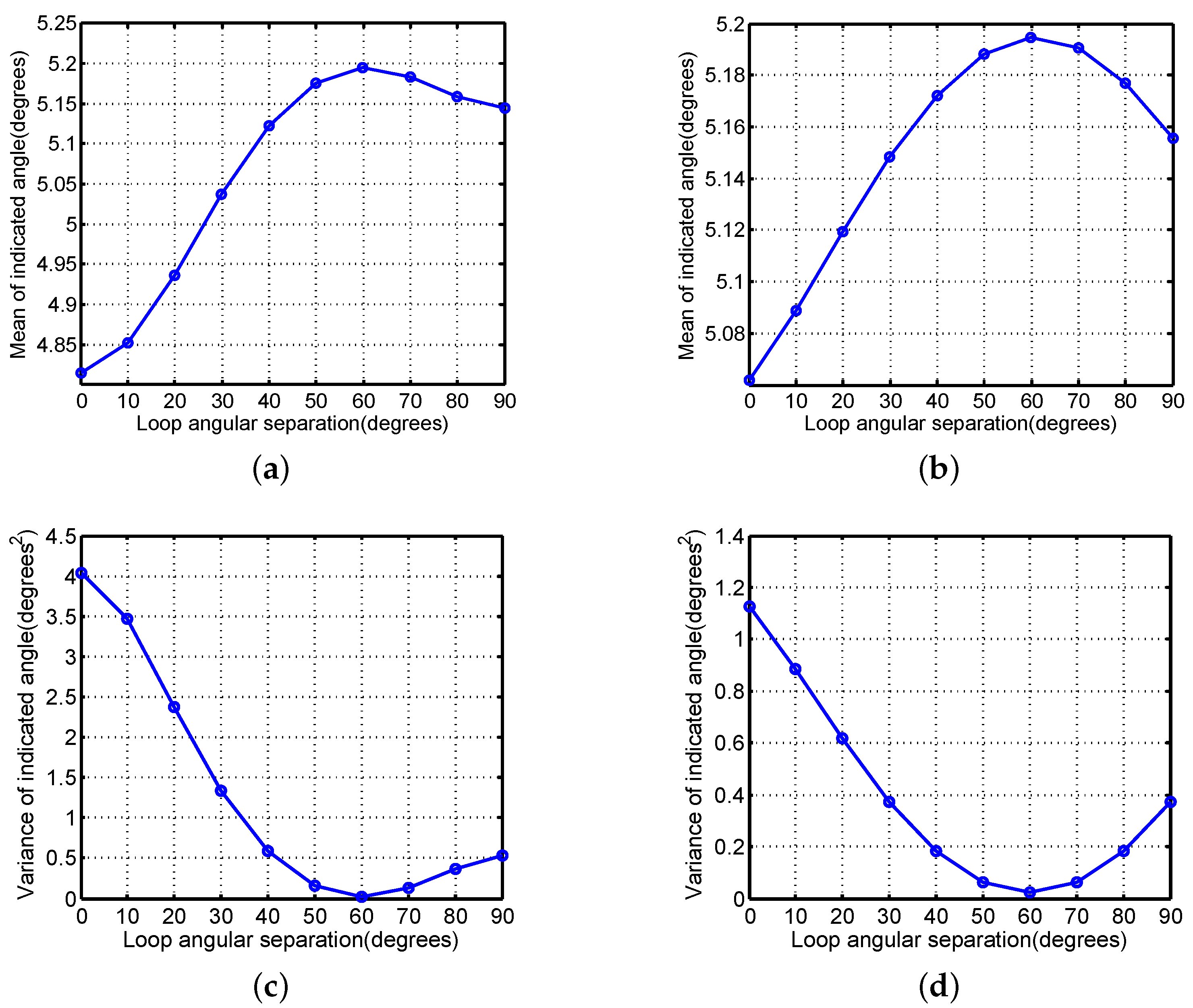
We use the arithmetic mean and variance of the monopulse-indicated angle to quantify the stable jamming performance. The arithmetic mean and variance of the monopulse-indicated angle for the cases considered in Figure 11 are plotted in Figure 12.
Figure 12 shows that the configuration α 1 = α 2 = α 3 = 60 has the largest arithmetic mean and the smallest variance of the monopulse-indicated angle compared to the other configurations considered. Hence, the configuration with uniform-spacing angular separation is the optimal configuration for modified C-MRCJ to achieve stable jamming performance.

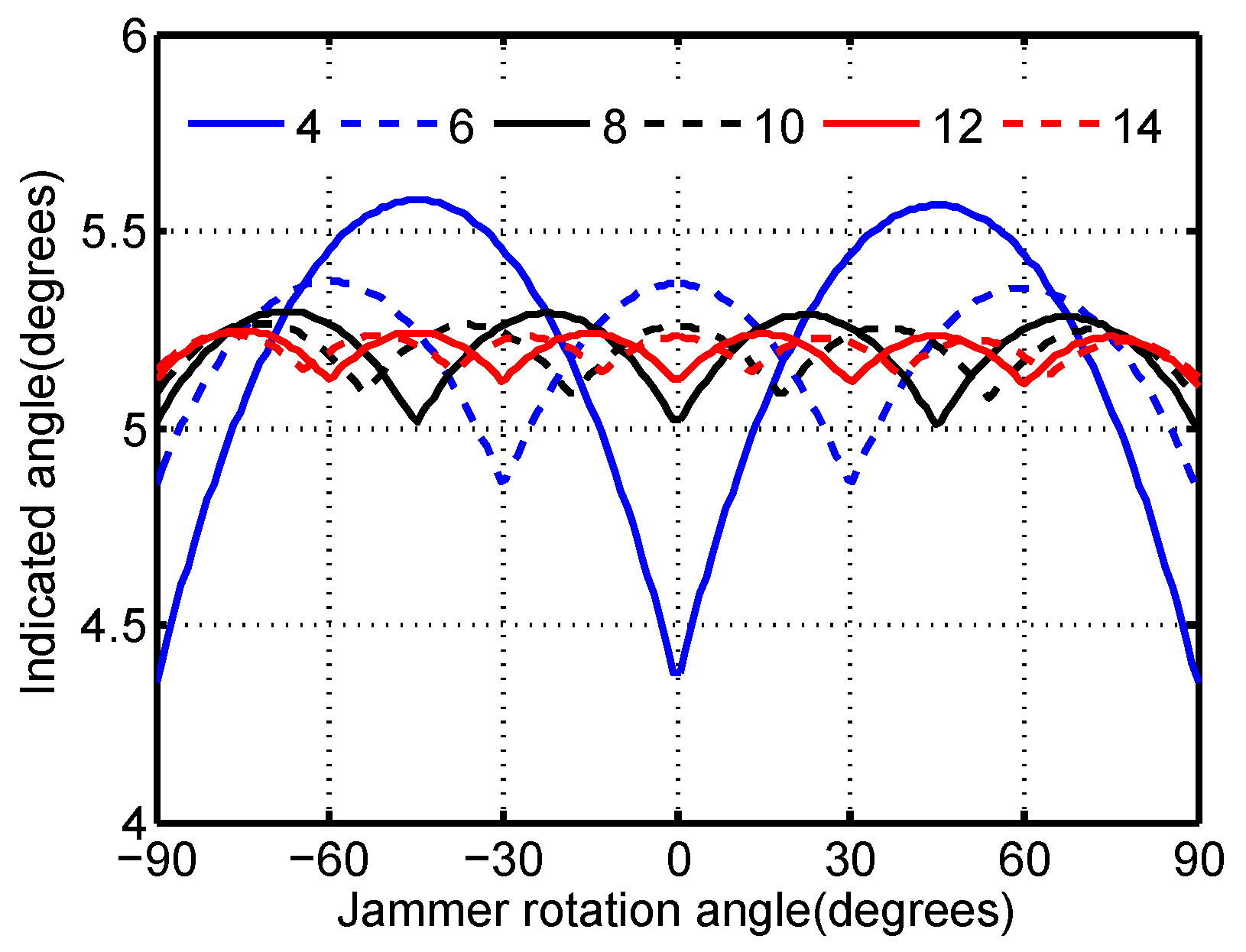
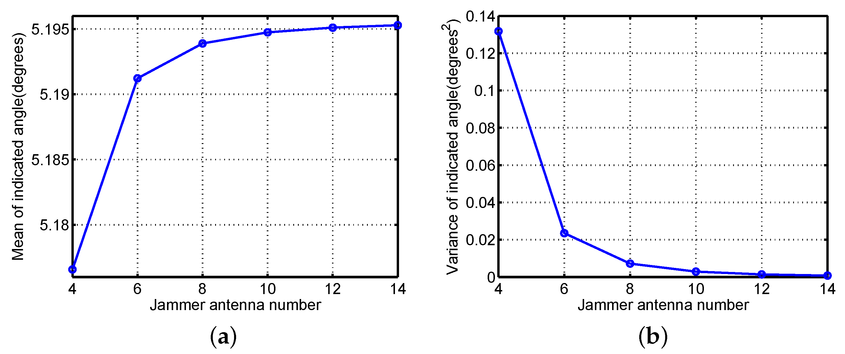
3.4. Choice of the Number of Antenna Elements

The choice of the number of antenna elements is discussed, giving consideration to the hardware cost and the jamming performance. The monopulse-indicated angles of modified C-MRCJ with the optimal configuration for a range of antenna numbers are plotted in Figure 13, and their arithmetic mean and variance are plotted in Figure 14.
Figure 13 shows that the stability of the induced angular error is improved by increasing antenna elements, although the improvement of the stability is not significant. This conclusion can also be obtained by Figure 14. The arithmetic mean and the variance of the indicated angle increases and decreases, respectively, as the number of the jammer antenna elements increases. Moreover, the enhancement of the stability is obvious when increasing antenna elements from 4 to 6. Hence, considering the stable jamming performance, the antenna array analyzed in [25] is not the best configuration.
However, the slightly enhanced performance of modified C-MRCJ by increasing antenna numbers is not tempting enough, because a large number of antenna elements will make the jammer system more complicated. Given that four antenna elements lead to poor jamming performance and eight or more antenna elements raise the hardware cost, six antenna elements are recommended for modified C-MRCJ.

4. Conclusions

MRCJ employing a circular retrodirective array was proposed in this paper. After defining the modulation direction of the jammer loop, the modified C-MRCJ was further presented to pursue continuous and stable jamming performance wherever the radar being jammed appears.
There is no superiority for C-MRCJ to induce large angular error compared to L-MRCJ. The difference between C-MRCJ and L-MRCJ is that the factor affecting the value of cross-eye gain is different. Simulation results demonstrated that modified C-MRCJ can achieve continuous jamming performance by modifying the MDs of jammer loops according to the DOA information. Meanwhile, The optimal configuration of modified C-MRCJ with uniform-spacing angular separation between jammer loops can provide the stablest jamming performance. Six antenna elements are recomended for modified C-MRCJ which has considerable jamming performance and moderate hardware cost.
Actually, for the practical platform protected by a cross-eye jammer, such as a ship or aircraft, the antenna configuration proposed is too idealistic. The MRCJ with distributed jammer loops appropriate for the practical platform geometry will be worth researching.

Author Contributions

Conceptualization, T.L. and X.W.; methodology, T.L.; software, T.L. and Z.L.; validation, T.L. and Z.G.; formal analysis, T.L.; investigation, X.W.; resources, X.W.; data curation, Z.L.; writing–original draft preparation, T.L.; writing–review and editing, T.L. and X.W.; visualization, Z.G.; supervision, X.W.; project administration, Z.L.; funding acquisition, T.L.

Funding

This research was supported by the Natural Science Foundation of China (Grant No. 61801488).

Acknowledgments

The authors would like to thank the editor and the anonymous reviewers for their valuable comments and suggestions to improve the quality of this paper.

Conflicts of Interest

The authors declare no conflict of interest.

Abbreviations

The following abbreviations are used in this manuscript:
MRCJMultiple-element Retrodirective Cross-eye Jamming
C-MRCJMRCJ employing a Circular array
JSRJammer-to-Signal Ratio
TRCJTwo-element Retrodirective Cross-eye Jamming
MCJMultiple-element Cross-eye Jamming
L-MRCJMRCJ employing a Linear array
DOADirection Of Arrival
MDModulation Direction
MAWMissile Approach Warner

References

  1. Schleher, D.C. Electronic Warfare in the Information Age; Artech House: Boston, MA, USA, 1999; pp. 262–278. [Google Scholar]
  2. Adamy, D.L. EW 101: A First Course in Electronic Warfare; Artech House: Boston, MA, USA, 2001; pp. 48–50. [Google Scholar]
  3. Redmill, P.E. The Principles of Artificial Glint Jamming (“Cross Eye”); Tech. note RAD. 831; Royal Aircraft Establishment: Farnborough, UK, 1963. [Google Scholar]
  4. du Plessis, W.P. A Comprehensive Investigation of Retrodirective Cross-Eye Jamming. Ph.D. Thesis, University of Pretoria, Pretoria, South Africa, 2010. [Google Scholar]
  5. du Plessis, W.P.; Odendaal, J.W.; Joubert, J. Extended analysis of retrodirective cross-eye jamming. IEEE Trans. Antennas Propag. 2009, 57, 2803–2806. [Google Scholar] [CrossRef]
  6. du Plessis, W.P.; Odendaal, J.W.; Joubert, J. Experimental simulation of retrodirective cross-eye jamming. IEEE Trans. Aerosp Electron Syst. 2011, 47, 734–740. [Google Scholar] [CrossRef]
  7. du Plessis, W.P.; Odendaal, J.W.; Joubert, J. Tolerance analysis of cross-eye jamming systems. IEEE Trans. Aerosp Electron Syst. 2011, 47, 740–745. [Google Scholar] [CrossRef]
  8. du Plessis, W.P. Platform skin return and retrodirective cross-eye jamming. IEEE Trans. Aerosp Electron Syst. 2012, 48, 490–501. [Google Scholar] [CrossRef]
  9. du Plessis, W.P. Limiting Apparent Target Position in Skin-Return Influenced Cross-Eye Jamming. IEEE Trans. Aerosp Electron Syst. 2013, 49, 2097–2101. [Google Scholar] [CrossRef] [Green Version]
  10. Petersson, B. Error estimation in retrodirective channel implementation. In Proceedings of the 2017 IEEE International Conference on Microwaves, Antennas, Communications and Electronic Systems (COMCAS), Tel-Aviv, Israel, 13–15 November 2017; pp. 1–6. [Google Scholar]
  11. Musso, C.; Curt, C. Robustness of a new angular countermeasure. In Proceedings of the Radar 97, Edinburgh, Scotland, 14–16 October 1997; pp. 415–419. [Google Scholar]
  12. Harwood, N.M.; Dawber, W.N.; Kluckers, V.A.; James, G.E. Multiple-element crosseye. IET Radar Sonar Navig. 2007, 1, 67–73. [Google Scholar] [CrossRef]
  13. Liu, T.; Liao, D.; Wei, X.; Li, L. Performance analysis of multiple-element retrodirective cross-eye jamming employing a linear array. IEEE Trans. Aerosp Electron Syst. 2015, 51, 1867–1876. [Google Scholar] [CrossRef]
  14. Liu, T.; Liu, Z.; Liao, D.; Wei, X. Platform skin return and multiple-element linear retrodirective cross-eye jamming. IEEE Trans. Aerosp Electron Syst. 2016, 52, 821–835. [Google Scholar] [CrossRef]
  15. du Plessis, W.P. Cross-eye gain in multi-loop retrodirective cross-eye jamming. IEEE Trans. Aerosp Electron Syst. 2016, 52, 875–882. [Google Scholar] [CrossRef]
  16. du Plessis, W.P. Path-length effects in multi-loop retrodirective cross-eye jamming. IEEE Antennas Wirel. Propag Lett. 2016, 15, 626–629. [Google Scholar] [CrossRef]
  17. du Plessis, W.P. Analysis of Path-Length Effects in Multiloop Cross-Eye Jamming. IEEE Trans. Aerosp Electron Syst. 2017, 53, 2266–2276. [Google Scholar] [CrossRef]
  18. du Plessis, W.P. Path-length compensation in multi-loop retrodirective cross-eye jamming. IEEE Trans. Aerosp Electron Syst. 2019, 55, 397–406. [Google Scholar] [CrossRef]
  19. Yang, D.; Liang, B.; Zhao, D. Cross-eye gain distribution of multiple-element retrodirective cross-eye jamming. J. Syst. Eng. Electron. 2018, 29, 1170–1179. [Google Scholar]
  20. Defensive Aids System. Available online: https://en.wikipedia.org/wiki/Defensive_aids_system (accessed on 29 March 2018).
  21. Neri, F. Anti-monopulse jamming techniques. In Proceedings of the 2001 SBMO/IEEE MTT-S International Microwave and Optoelectronics Conference, Belem, Brazil, 6–10 August 2001; pp. 45–50. [Google Scholar]
  22. Ciuonzo, D.; De Maio, A.; Orlando, D. A Unifying framework for adaptive radar detection in homogeneous plus structured interference-part II: Detectors design. IEEE Trans. Signal Process. 2016, 64, 2907–2919. [Google Scholar] [CrossRef]
  23. Ciuonzo, D.; De Maio, A.; Orlando, D. On the statistical invariance for adaptive radar detection in partially homogeneous disturbance plus structured interference. IEEE Trans. Signal Process. 2017, 65, 1222–1234. [Google Scholar] [CrossRef]
  24. Carotenuto, V.; Aubry, A.; Ciuonzo, D. Rician MIMO channel- and jamming-aware decision fusion. IEEE Trans. Signal Process. 2017, 65, 3866–3880. [Google Scholar]
  25. Liu, S.; Dong, C.; Xu, J.; Zhao, G.; Zhu, Y. Analysis of rotating cross-eye jamming. IEEE Antennas Wirel. Propag Lett. 2015, 14, 939–942. [Google Scholar] [CrossRef]
  26. du Plessis, W.P. Modelling monopulse antenna patterns. In Proceedings of the 2013 Saudi International Electronics, Communications and Photonics Conference (SIECPC 2013), Riyadh, Saudi Arabia, 27–30 April 2013; pp. 1–5. [Google Scholar]
Figure 1. A retrodirective cross-eye jamming system with two antenna elements.
Electronics 08 00806 g001
Figure 2. The jamming geometry where C-MRCJ deceives a phase-comparison monopulse radar.
Electronics 08 00806 g002
Figure 3. DOA information and modulation direction for C-MRCJ with three jammer loops.
Electronics 08 00806 g003
Figure 4. The flow diagram of signal processing of modified C-MRCJ.
Electronics 08 00806 g004
Figure 5. The process of MD modification for modified C-MRCJ.
Electronics 08 00806 g005
Figure 6. Two different configurations of C-MRCJ with six antenna elements. The platform is denoted by a black square. (a) Configuration 1 where α 1 = α 3 = 15 , α 2 = 150 . (b) Configuration 2 where α 1 = α 2 = α 3 = 60 .
Electronics 08 00806 g006
Figure 7. Configuration of L-MRCJ with six antenna elements. The base-lengths of the three jammer loops are d c , 4 d c / 5 and 3 d c / 5 , respectively.
Electronics 08 00806 g007
Figure 8. Monopulse-indicated angles of different jammer array configurations when the radar antennas rotate. The system parameters of TRCJ are 0.5 dB and 180 , and the system parameters of L-MRCJ and C-MRCJ which are a 1 = a 3 = 0.5 dB, a 2 = 0.5 dB, ϕ 1 = ϕ 2 = ϕ 3 = 180 .
Electronics 08 00806 g008
Figure 9. Monopulse-indicated angles of L-MRCJ and C-MRCJ when the jammer antennas rotate. (a) The system parameters are a 1 = a 2 = a 3 = 0.5 dB , ϕ 1 = ϕ 2 = ϕ 3 = 180 . (b) The system parameters are a 1 = 0.5 dB , a 2 = 1.5 dB , a 3 = 2.5 dB , ϕ 1 = 170 , ϕ 2 = 175 , ϕ 3 = 180 .
Electronics 08 00806 g009
Figure 10. Monopulse-indicated angles of L-MRCJ and modified C-MRCJ when the jammer antennas rotate. (a) The system parameters are a 1 = a 2 = a 3 = 0.5 dB , ϕ 1 = ϕ 2 = ϕ 3 = 180 . (b) The system parameters are a 1 = 0.5 dB , a 2 = 1.5 dB , a 3 = 2.5 dB , ϕ 1 = 170 , ϕ 2 = 175 , ϕ 3 = 180 .
Electronics 08 00806 g010
Figure 11. Monopulse-indicated angles for different configurations when the jammer antennas rotate. The system parameters are a 1 = a 2 = a 3 = 0.5 dB, ϕ 1 = ϕ 2 = ϕ 3 = 180 . (a) Symmetrical case. (b) Asymmetrical case.
Electronics 08 00806 g011
Figure 12. The arithmetic mean and variance of monopulse-indicated angle. (a) Arithmetic mean for the symmetrical case. (b) Arithmetic mean for the asymmetrical case. (c) Variance for the symmetrical case. (d) Variance for the asymmetrical case.
Electronics 08 00806 g012
Figure 13. Monopulse-indicated angles of modified C-MRCJ with the optimal configuration for a range of antenna numbers when the jammer antennas rotate. The system parameters are a 1 = a 2 = a 3 = 0.5 dB, ϕ 1 = ϕ 2 = ϕ 3 = 180 .
Electronics 08 00806 g013
Figure 14. The arithmetic mean and variance of monopulse-indicated angle for different jammer antenna numbers. (a) Arithmetic mean. (b) Variance.
Electronics 08 00806 g014
Table 1. Details of MD for modified C-MRCJ.
DOA Information I 1 I 2 I 3
Direction in the region between antenna 1 and 2−111
Direction in the region between antenna 2 and 3−1−11
Direction in the region between antenna 3 and 4−1−1−1
Direction in the region between antenna 4 and 51−1−1
Direction in the region between antenna 5 and 611−1
Direction in the region between antenna 6 and 1111

