Abstract
A flexible antenna is a significant part of the new generation of wireless communication systems. Conventional antennas are typically fabricated on available FR-4 and RT/Duroid dielectric materials, where the dielectric constant cannot be selected arbitrarily and the degrees of freedom in designing the antenna are limited, whereas our flexible substrate offers moderate dielectric values by changing the concentration of the raw materials. Synthesised nickel particle-based flexible nickel aluminate (NiAl2O4) is utilized as a substrate material to make an effective antenna for microwave applications. The nickel aluminate substrate was made with 42% concentration of nickel, and has a dielectric constant of 4.979 and a thickness of 1 mm. The fabricated flexible antenna shows measured bandwidth from 6.50–8.85 GHz. On the other hand, the maximum measured gain and efficiency was 4.75 dBi and 91%, respectively. Finally, that antenna has directional radiation patterns and the presented antenna has a novelty where the nickel aluminate substrate was used for the first time. Thus the compactness of the antenna and its performance with a flexible nature makes it a worthy one to be used in the C-band application.
1. Introduction
Over the past few decades, the microstrip patch antenna has been used widely in wireless communication technology because of its optimal size and miniature shape characteristics. At present, flexible antennas are utilized due to their compactness with an advanced flexible substrate that can be easily integrated in electronic devises and cover their functional features. The low-cost flexible antennas are environmentally friendly and easy to manufacture. Various materials like conductive or non-conductive dielectrics are utilized to make this type of flexible antenna. The photolithography or etching processes are used to fabricate the antenna structure and creates large amount of waste due to its subtractive process. As a result, nowadays different types of flexible antennas are manufactured such as paper-based antennas [1], PET(Polyethylene terephthalate) substrates [2], polymer-based antennas [3], wearable antennas [4], fluidic antennas [5], textile antennas [6], carbon nanotube (CNT) antennas [7] and nickel-based metamaterial [8] for increasing the flexibility [9], reducing the waste, manufacturing cost and using low-cost materials.
In the developing field of wireless technology, a goal is to make flexible antennas having special properties with respect to those of bulk or single particle species. A low-cost paper-based flexible antenna for 2.45 GHz frequency band WLAN (wireless local area network) applications was presented by Anagnostou et al. The projected antenna was an IFA(Inverted-F antenna) with a backside ground plane and a topside metallic layer. The simulated and measured return loss have been in good agreement, with a −10 dB bandwidth that covers the entire WLAN frequency range. It detected only a 2% shift from what was expected [10]. Again, a flexible antenna based on a zero-order resonator was manufactured on liquid crystal polymer substrate (thickness of 100 μm) and the total dimension of the antenna was 30 × 30 mm2 presented by Choi et al. Once the proposed antenna is flat, it has the average and peak gain of −1.84 dBi and 4.98 dBi, respectively, at the resonance point 3.18 GHz. While the antenna is bent with +900, then the average and peak gains are sequentially −2.46 dBi and 2.99 dBi [11]. In 2012, the presented antenna was a compact and flexible CPW (coplanar waveguide)-fed, UWB (Ultra-wideband) antenna, which consists of an elliptical patch and a modified ground plane to achieve impedance bandwidth between 2.52 GHz to 13.35 GHz. The substrate was composed of 0.78 mm thickness denim textile which has a permittivity of 1.8 and tangent loss of 0.07 at 2.4 GHz [12]. A flexible coplanar-fed dual band antenna was built on Kaptonr polyimide substrate for 2.45 GHz and 5.80 GHz ISM bands by Mesquita et al. in 2013 [13]. A flexible antenna proposed on 101 µm Ultralam 3850 for microwave imaging was reported by Porter et al. in 2014. The total antenna size was 24 × 32 mm2. The simulated and measured S11 for the flexible antenna was over the 1.5 GHz to 4.5 GHz frequency band. The author reported a near omnidirectional and broadside near-field radiation pattern with an efficiency of 47% from simulations, when in interaction with skin [14]. In 2015, Jung et al. offered a simple approach to make an implantable, yet compact and flexible, monopole antenna consisting of meandered strips and a coupling patch, fabricated on a thin coating of ultrathin Parylene C film substrate. Moreover, the antenna was first designed to operate in air and tuned at later stage after studying the effects when implanted under porcine skin. The results of the S11 of the flexible dual band (2.4 GHz and 5.8 GHz). In addition, the 2.4 GHz and 5.8 GHz associated measured maximum radiation gains were –5.4 dBi and 3.8 dBi, respectively. The characteristics of the proposed antenna have also shown negligible change under different bending conditions [15]. A modified microstrip patch antenna was designed on Polyethylene terephthalate substrate for 5G applications in 2017. The 60 × 75 mm2 antenna was operated within 7.0 to 13 GHz and exhibits an almost omnidirectional radiation pattern with an average gain of 5 dBi [16]. Metallized form helps to design pico-cell based antenna operates at GSM850, GSM900, GSM1800, GSM1900, UMTS (Universal Mobile Telecommunications System), Bluetooth/WLAN, WiMAX (Worldwide Interoperability for Microwave Access), and Wi-Fi (wireless fidelity) which was shown total efficiency 75% [17].
In this paper, a new flexible antenna is introduced based on nickel aluminate (NiAl2O4) substrate with 42% nickel concentration which has been synthesized by the sol–gel method. The prepared flexible antenna shows the simulated bandwidth of 1.67 GHz from 7.05 to 8.72 GHz, whereas the resonance point is at 8.15 GHz. The measured results show the bandwidth of 2.35 GHz from 6.50 to 8.85 GHz, whereas the resonance is sequentially at 7.75 GHz. As a result, the fabricated flexible antenna is applicable for C-band application. The measured maximum and average antenna gain are 4.75 dBi and 3.75 dBi and the radiation characteristics have a directional pattern.
2. Design of Flexible Antenna
Flexible Antenna at 42% Concentration of Nickel
The schematic structure of the microstrip-fed patch antenna is shown in Figure 1a–b. This antenna is designed on a flexible nickel aluminate (NiAl2O4) material as a substrate material, where the molar ratio of [0.42(nickel):0.58(aluminium nitrate)]. Nickel aluminate (NiAl2O4) material is chosen as substrate material with permittivity of 4.97, loss tangent of 0.007 and thickness of 0.5 mm.
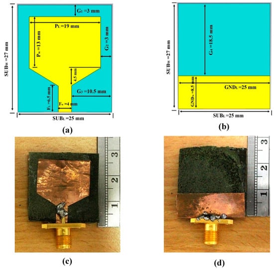
Figure 1.
Proposed antenna schematic (a) front view (b) back view of graphic structure and fabricated prototype (c) front view (d) back view on flexible nickel aluminate material at 42% concentration of nickel.
The antenna is excited with a microstrip feed line printed on the bottom layer of substrate and a 50Ω SMA (SubMiniature version A) connector connected with the feed line and ground plane each other. In the figure, the antenna structure consists of a 19 × 13 mm2 rectangular patch and a 25 × 8.5 mm2 rectangular ground plane as well, the total length of the feed line is 6.5 mm, whereas the width is 4 mm. Moreover, the gaps between the patch and nickel aluminate substrate edge are 3 mm. Figure 1c–d shows the fabricated antenna prototype and Table 1 demonstrates the detail design specification of the antenna.

Table 1.
Design specification of the proposed flexible antenna at 42% concentration of nickel.
3. Methodology and Measurement
Electromagnetic simulation helps estimating the fundamental field quantities from Maxwell’s equation adopting some numerical methods. It is important to undertake a highly exact design and investigation of confounded microwave and RF (radio frequency) printed circuit, antenna and other electronic segments. This also clarifies the electromagnetic wave propagation and interactions with metamaterials. Finite-difference time-domain method-based CST (computer simulation technology) Microwave Studio is used for obtaining the reflection coefficient, VSWR (voltage standing wave ratio), gain, efficiency and radiation patters for the designed antennas. A vector network analyzer Agilent P-series VNA (Vector network analyzer) (Agilent N5227A) equipped with two ports is used for the measurement. The calibration prior is required for error-free measurement. Scattering parameters return loss, VSWR and the phase of input impedance measurements are achieved by linking the fabricated antenna to port-1 of the network analyzer via a semi-rigid cable.
The radiation behaviors of the designed flexible antennas at 42% concentration of nickel have been measured in an anechoic chamber bounded near field measurement lab (UKM Satimo Star Lab) shown in Figure 2. The fabricated antenna is placed on the test board which is located at the center of a circular “arch” that covers 16 probes and the spacing between two probes is 22.5°. This spacing is appropriate for small antenna testing. For larger antennas, the position of the probe array can be mechanically offset. The antenna is rotated horizontally through 360° and summary of 360° rotation and array of 16 probes give a full wave 3D-scan of the under-tested antenna. To realize unlimited near-field sampling, the consuming standard spherical ray propagation technique and software are utilized to feed the radiation pattern that are entirely defined by a set of modal coefficients. To increase the efficiency and reduce the reflected signal of the designed antenna the absorbers are used to absorb the unwanted signal inside the anechoic chamber.
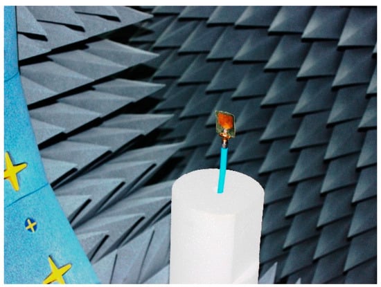
Figure 2.
Measurement setup of designed flexible antennas at 42% concentration of nickel in Satimo Star Lab.
4. Results and Discussion
4.1. Preparation of Flexible Nickel Aluminate (NiAl2O4)
The sol–gel method is used to manufacture the final substrate [18]. Figure 3 presents a flow chart of the synthesis steps of nickel aluminate powder by the sol–gel method. For the preparation of nickel aluminate composite, initially two raw materials aluminium nitrate nonahydrate Al(NO3)3.9H2O and nickel nitrate hexahydrate Ni(NO3)2.6H2O were used in a molar ratio of [0.42(nickel):0.58 (aluminium nitrate)] for 42% concentration of nickel to make the solution. The subsequent complex solution became viscous, has transparent characteristics, and exhibits a light green colour. The water evaporates from the ready solution, and it is heated up to 90 °C and stirred endlessly for about 4 hours. The water completely evaporated and gave the impression of a greenish gel. The gel is placed into an alumina crucible furnace at 150 °C for the rest of the chemical reaction and for obtaining fine powder. At that time, the precursor was ground appropriately and for 1 hour calcined at 450 °C, and then we waited until the chemical reaction finished. Then dissolved polyvinyl acetate (PVA) adding to the synthesized NiAl2O4 powder and made the fabricated substrate followed by stirring. Figure 3 shows the total preparation process of nickel aluminate (NiAl2O4) powder and fabricated nickel aluminate (NiAl2O4) material at a concentration of 42% nickel, termed Ni42.

Figure 3.
Preparation flowchart and process of fabrication of nickel aluminate (NiAl2O4) material.
Table 2 shows the relative molecular mass (JMR) and the volume of solvent and other materials used to produce solutions for calculation purposes. In this research, aluminium nitrate nonahydrate Al (NO3)3.9H2O and nickel nitrate hexahydrate Ni (NO3)2.6H2O were taken as raw materials to make the NiAl2O4 composite specimens using the well-known sol–gel method.
Table 2.
JMR information of the raw material.
4.2. Flexible Antenna at 42% Concentration of Nickel
Numerical and measured results of the fabricated flexible antenna, where the concentration of nickel is 42%, are shown in Figure 4. The simulated resonance bandwidth is from 7.05 to 8.72 GHz (bandwidth of 1.67 GHz), whereas the measured resonance bandwidth is from 6.50 to 8.85 GHz (bandwidth of 2.35 GHz). As a result, from the resonance bandwidth it can be said that the fabricated antenna is applicable for C-band (6.50 GHz to 8.85 GHz) applications. In addition, the simulated resonance point is at 8.15 GHz, but the measured resonance point is at 7.75 GHz. Besides, from the results it is seen that there is a variation between the simulated and measured results. There are some pores in the substrate, which is why the effective area of the fabricated antenna is reduced than the simulated one. The impedance mismatch between the SMA connectors, the feedline fabrication and soldering tolerance of the antenna along with improper calibration of the VNA and Satimo chamber were possible reasons for the discrepancy of the simulated and measured results.
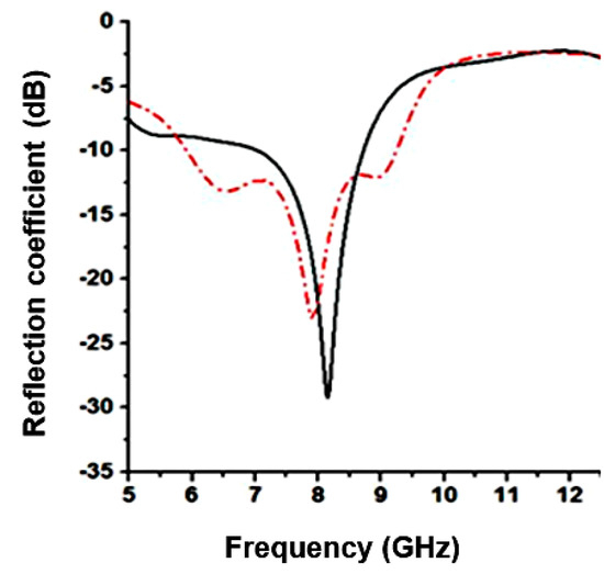
Figure 4.
Simulated and measured return loss of the designed flexible antenna at 42% concentration of nickel.
The measured and simulated gain of the antenna are shown in Figure 5a. Antenna gain is related to size of the antenna, substrate material properties and multiple layer of the substrate. The proposed compact antenna is designed on flexible nickel aluminate (NiAl2O4) material where the ratio of nickel is 42%. The antenna has simulated maximum and average gain and are sequentially, 5.25 dBi and 4.25 dBi. In addition, the measured maximum and the average gain are 4.75 dBi and 3.75 dBi, respectively. Antenna efficiency is central importance in predicting radio communications reliability. It is the measurement of conversion of electrical current to radiated electromagnetic wave. New materials and smaller antennas are of significant interest to reduce e-waste and to make fabrication easier. A low-efficiency antenna has reduced gain and so the communications range is reduced. The fundamental limits on the maximum radiation efficiency are the various antenna parameters such as bandwidth, gain, Q factor and so on. Figure 5b shows the total efficiency of the proposed flexible antenna where the measured average efficiency is 85% and the maximum efficiency is 91%, whereas the simulated average efficiency is 85% and the maximum efficiency is 96%.
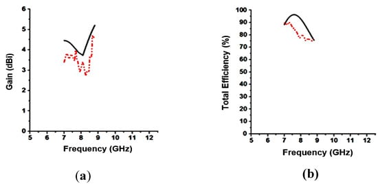
Figure 5.
Measured and simulated, (a) gain and (b) total efficiency of the designed flexible antenna; at 42% concentration of nickel.
The current distribution of the designed antenna at the resonant frequencies 8.15 GHz is shown in Figure 6. The patch is a short resonant length of low-impedance and have high magnitude in the edges and maximum current distribution at the center of the patch at the resonant frequency. The distribution strongly depends on the height of substrate which is obtainable for the antenna size. The electric surface current density at each position on the lower surface is equal to the magnetic field under the patch.
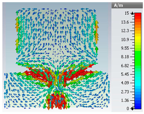
Figure 6.
Surface current distribution in 8.15 GHz at 42% concentration of nickel.
Both simulated and measured radiation patterns in the case of co-polarization and cross-polarization in the E-plane and H-plane are compared in Figure 7a,b respectively, whereas Eθ represents the co-polarization and Eφ represents the cross-polarization. The co-polarization is more noteworthy than the cross-polarization in both E-plane and H-plane. The radiation pattern exhibited that at 7.75 GHz, the current is well distributed over the patch, and the patterns are almost directional. Moreover, a better radiation pattern depends basically on precisely situating the probe, and reducing distortions in the field presented by the room or track.
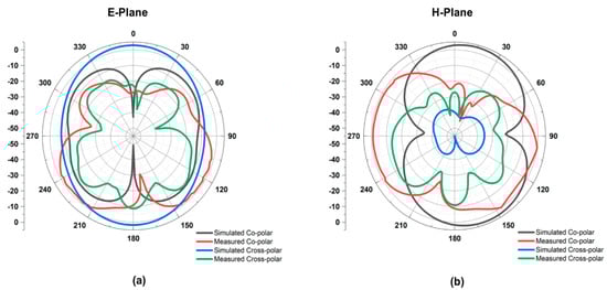
Figure 7.
Simulated and measured radiation pattern of the proposed flexible antenna in 7.75 GHz in (a) E-Plane and (b) H-plane.
4.3. Parametric Analysis of the Proposed Flexible Patch Antenna
Figure 8a–d present the parametric analysis of the designed antenna, which is necessary to understand the effects of different elements in antenna geometry and how the elements affect the antenna performances. In Figure 8a–b a rectangular radiating patch is attached where the current is distributed well around the patch and expands the bandwidth and gain. The dimension of the ground plane is not so high, so less current is distributed on the ground plane and has less effect on the antenna performance. At the time of operation, the antenna acts like a capacitor or inductor, when the signals with phases are passes through the antenna. At low frequency operation the antenna radiating patch is not a good conductor, so conductivity is improved by the ground or additional metal strips. In Figure 8c the radiating patch structure is cut like triangle and finally a metallic strip relates to the upper edge of the triangular patch and generates a slot as shown in Figure 8d. The performance of all antenna structures is displayed in Figure 9. From Figure 9, the proposed antennas have optimal compute results in respect of VSWR. If the VSWR is lower than 2.0, the antenna impedance match is considered perfect and antenna performed well but when VSWR are increased more than 2.0 then the antenna starts to reflect more power and therefore does not transmit. Table 3 represents the band of frequencies; where VSWR are lower than 2.0 at different structural arrangement of the proposed antenna configuration.
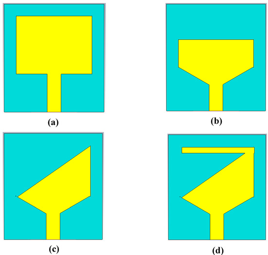
Figure 8.
Structural parametric analysis of antenna (a) patch structure-1 (b) patch structure-2 (c) patch structure-3 and (d) patch structure-4.
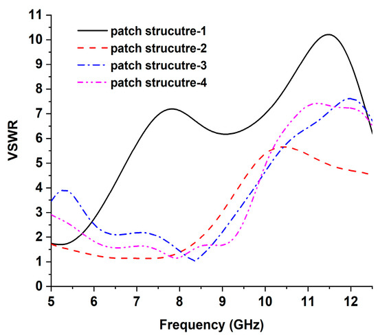
Figure 9.
The effects of different radiating patch structures of antenna voltage standing wave ratio (VSWR).
Table 3.
Comparison of the radiating patch effects on voltage standing wave ratio.
To confirm the novelty of the proposed flexible antennas, Table 4 summarizes the performances of the proposed antennas in terms of size in the antenna, impedance bandwidth, gain, efficiency, radiation patter and application. From Table 4, it can be seen that the proposed antennas are compact in size, have larger bandwidth, acceptable gain, efficiency and directional radiation patterns. The antennas are fabricated on the flexible nickel aluminate (NiAl2O4) material at 42% concentration, whereas the operating frequency from 5 GHz to 12 GHz. In addition, the flexible antenna has efficiency of 91% as well as gain of 4.75 dBi, respectively. Besides, the antenna has a directional radiation pattern and is applicable for C-band (at 42% concentration) application.
Table 4.
Performance summary of the proposed flexible material-based patch antennas.
Table 5 demonstrates the comparison between the developed flexible material antenna with the existing various flexible material antennas. From the table, the largest antenna was presented by Kaur et al. But the antenna gain was high, and bandwidth was narrow. Porter et al. developed an antenna on flexible Rogers Ultralam 3850 material whose dimension was 24 × 32 mm2, bandwidth of 3.0 GHz, and gain of 2.7 dBi, for microwave imaging applications. Furthermore, Simorangkir et al. also established an 80 × 67 mm2 antenna on flexible polydi methylsiloxane material, which had 6.0 GHz wide bandwidth and 4.53 dBi gain for UWB applications. In this research, the antenna is developed using flexible nickel aluminate as a substrate material. The reported antennas are compact in size (25×27 mm2), large bandwidth, high gain and applicable for C-band application.
Table 5.
Comparison between the proposed and existing material antennas.
5. Conclusions
The flexible antenna has been analyzed, designed and developed on prepared flexible nickel aluminate (NiAl2O4) material. The developed flexible nickel aluminate (NiAl2O4) material has dielectric permittivity of 4.97 as well as loss tangent of 0.007 at 42% concentration of nickel. The developed antenna shows that simulated resonance bandwidth is from 7.05 to 8.72 GHz (bandwidth of 1.67 GHz), whereas the measured resonance bandwidth is from 6.5 to 8.85 GHz (bandwidth of 2.35 GHz). As a result, the fabricated flexible antenna is applicable for C-band applications with the maximum measured gain of 4.75 dBi. The optimal performances of the compact flexible antenna validate has potential as a suitable candidate for microwave frequency region applications in the near future.
Author Contributions
M.A.R. and M.R.I.F. made substantial contributions to conception, materials preparation, design, characterization and analysis. E.A. participated in the analysis and critical revision of the article for important intellectual content. M.T.I. and M.S. provided necessary instructions for experimental purposes.
Funding
This work was supported by the Fundamental Research Grant, Ministry of Education, Code: FRGS/1/2018/TK04/UKM/02/13.
Conflicts of Interest
The authors declare no conflict of interest.
References
- AbuTarboush, H.F.; Shamim, A. Paper-Based Inkjet-Printed Tri-Band U-Slot Monopole Antenna for Wireless Applications. IEEE Antennas Wirel. Propag. Lett. 2012, 11, 1234–1237. [Google Scholar] [CrossRef]
- Faraj, M.G.; Ibrahim, K.; Ali, M.K.M. PET as a plastic substrate for the flexible optoelectronic applications. Optoelectronics and Advanced Materials. Rapid Commun. 2011, 5, 879–882. [Google Scholar]
- Khaleel, H.R.; Al-Rizzo, H.M.; Rucker, D.G. Compact Polyimide-Based Antennas for Flexible Displays. J. Disp. Technol. 2012, 8, 91–97. [Google Scholar] [CrossRef]
- Jiang, Z.H.; Brocker, D.E.; Sieber, P.E.; Werner, D.H. A Compact, Low-Profile Metasurface-Enabled Antenna for Wearable Medical Body-Area Network Devices. IEEE Trans. Antennas Propag. 2014, 62, 4021–4030. [Google Scholar] [CrossRef]
- Ramli, M.N.; Soh, P.J.; Jamlos, M.F.; Lago, H.; Aziz, N.M.; Al-Hadi, A.A. Dual-band wearable fluidic antenna with metasurface embedded in a PDMS substrate. Appl. Phys. A 2017, 123, 149. [Google Scholar] [CrossRef]
- Sun, Y.; Yuk, T.I.; Cheung, S.W. Design of a textile ultra-wideband antenna with stable performance for body-centric wireless communications. IET Microwaves Antennas Propag. 2014, 8, 1363–1375. [Google Scholar] [CrossRef]
- Bengio, E.A.; Senic, D.; Taylor, L.W.; Tsentalovich, D.E.; Chen, P.; Holloway, C.L.; Babakhani, A.; Long, C.J.; Novotny, D.R.; Booth, J.C.; et al. High efficiency carbon nanotube thread antennas. Appl. Phys. Lett. 2017, 111, 163109. [Google Scholar] [CrossRef]
- Ahamed, E.; Hasan, M.M.; Faruque, M.R.I.; Bin Mansor, M.F.; Abdullah, S.; Islam, M.T. Left-handed metamaterial inspired by joint T-D geometry on flexible NiAl2O4 substrate. PLOS ONE 2018, 13, e0199150. [Google Scholar] [CrossRef] [PubMed]
- Hasan, M.M.; Faruque, M.R.I.; Islam, M.T. Dual Band Metamaterial Antenna For LTE/Bluetooth/WiMAX System. Sci. Rep. 2018, 8, 1240. [Google Scholar] [CrossRef] [PubMed]
- Anagnostou, D.E.; Gheethan, A.A.; Amert, A.K.; Whites, K.W. A Direct-Write Printed Antenna on Paper-Based Organic Substrate for Flexible Displays and WLAN Applications. J. Disp. Technol. 2010, 6, 558–564. [Google Scholar] [CrossRef]
- Choi, S.W.; Lee, H.J.; Lee, J.Y.; Lee, K.B. CPW-fed compact flexible antenna based on a zeroth-order resonator. In Proceedings of the 2011 IEEE International Symposium on Antennas and Propagation (APSURSI), Spokane, WA, USA, 3–8 July 2011. [Google Scholar]
- Jalil, M.E.; Rahim, M.K.A.; Abdullah, M.A.; Ayop, O. Compact CPW-fed Ultra-wideband (UWB) antenna using denim textile material. In International Symposium on Antennas and Propagation. In Proceedings of the 2012 International Symposium on Antennas and Propagation (ISAP), Nagoys, Japan, 29 October–2 November 2012. [Google Scholar]
- Mesquita, J.M.; Pires, N.; Moreira, A.A. Influence of deformations on the matching of a flexible dual-band antenna. In Proceedings of the 2013 7th European Conference on Antennas and Propagation (EuCAP), Gothenburg, Sweden, 8–12 April 2013. [Google Scholar]
- Porter, E.; Walls, G.; Zhou, Y.; Popovic, M.; Schwartz, J.D. A FLEXIBLE BROADBAND ANTENNA AND TRANSMISSION LINE NETWORK FOR A WEARABLE MICROWAVE BREAST CANCER DETECTION SYSTEM. Prog. Electromagn. Res. Lett. 2014, 49, 111–118. [Google Scholar] [CrossRef]
- Jung, Y.H.; Qiu, Y.; Lee, S.; Shih, T.Y.; Xu, Y.; Xu, R.; Lee, J.; Schendel, A.A.; Lin, W.; Williams, J.C.; et al. A compact parylene coated WLAN flexible antenna for implantable electronics. IEEE Antenn. Wirel. Propag. Lett. 2015, 15, 1382–1385. [Google Scholar] [CrossRef]
- Tighezza, M.; Rahim, S.K.A.; Islam, M.T. Flexible wideband antenna for 5G applications. Microw. Opt. Technol. Lett. 2017, 60, 38–44. [Google Scholar] [CrossRef]
- Anguera, J.; Daniel, J.P.; Borja, C.; Mumbrú, J.; Puente, C.; Leduc, T.; Sayegrih, K.; Roy, P.V. Metallized Foams for Antenna Design: Application to Fractal-Shaped Sierpinski-Carpet Monopole. Prog. Electromagn. Res. 2010, 104, 239–251. [Google Scholar] [CrossRef]
- Rahman, M.A.; Ahamed, E.; Faruque, M.R.I.; Islam, M.T. Preparation of NiAl2O4-Based Flexible Substrates for Metamaterials with Negative Dielectric Properties. Sci. Rep. 2018, 8, 14948. [Google Scholar] [CrossRef] [PubMed]
- Kaur, A.; Aastha; Kalra, P.; Sidhu, E. Flexible novel trident shaped microstrip patch antennas design employing Teflon substrate. In Proceedings of the Flexible novel trident shaped microstrip patch antennas design employing Teflon substrate, Allahbad, India, 21–22 October 2016. [Google Scholar]
- Simorangkir, R.B.V.B.; Kiourti, A.; Esselle, K.P. UWB Wearable Antenna With a Full Ground Plane Based on PDMS-Embedded Conductive Fabric. IEEE Antennas Wirel. Propag. Lett. 2018, 17, 493–496. [Google Scholar] [CrossRef]


© 2019 by the authors. Licensee MDPI, Basel, Switzerland. This article is an open access article distributed under the terms and conditions of the Creative Commons Attribution (CC BY) license (http://creativecommons.org/licenses/by/4.0/).