Article

Remote-Controlled Fully Implantable Neural Stimulator for Freely Moving Small Animal

1
Department of Electrical and Computer Engineering, College of Engineering, Seoul National University, Seoul 08826, Korea
2
Inter-University Semiconductor Research Center, Seoul National University, Seoul 08826, Korea
3
Department of Neurosurgery, College of Medicine, Yonsei University, Seoul 03722, Korea
4
Department of Biomedical Engineering, School of Medicine, Pusan National University, Yangsan 50612, Korea
5
Institute on Aging, College of Medicine, Seoul National University, Seoul 08826, Korea
*
Author to whom correspondence should be addressed.
Electronics 2019, 8(6), 706; https://doi.org/10.3390/electronics8060706
Submission received: 11 May 2019 / Revised: 14 June 2019 / Accepted: 18 June 2019 / Published: 22 June 2019
(This article belongs to the Special Issue Smart Electrical Circuits and Systems for Neural Interface)

Abstract

:
The application of a neural stimulator to small animals is highly desired for the investigation of electrophysiological studies and development of neuroprosthetic devices. For this purpose, it is essential for the device to be implemented with the capabilities of full implantation and wireless control. Here, we present a fully implantable stimulator with remote controllability, compact size, and minimal power consumption. Our stimulator consists of modular units of (1) a surface-type cortical array for inducing directional change of a rat, (2) a depth-type array for providing rewards, and (3) a package for accommodating the stimulating electronics, a battery and ZigBee telemetry, all of which are assembled after independent fabrication and implantation using customized flat cables and connectors. All three modules were packaged using liquid crystal polymer (LCP) to avoid any chemical reaction after implantation. After bench-top evaluation of device functionality, the stimulator was implanted into rats to train the animals to turn to the left (or right) following a directional cue applied to the barrel cortex. Functionality of the device was also demonstrated in a three-dimensional (3D) maze structure, by guiding the rats to better navigate in the maze. The movement of the rat could be wirelessly controlled by a combination of artificial sensation evoked by the surface electrode array and reward stimulation. We could induce rats to turn left or right in free space and help their navigation through the maze. The polymeric packaging and modular design could encapsulate the devices with strict size limitations, which made it possible to fully implant the device into rats. Power consumption was minimized by a dual-mode power-saving scheme with duty cycling. The present study demonstrated feasibility of the proposed neural stimulator to be applied to neuroprosthesis research.

1. Introduction

Brain–computer interface technology has shown a wide range of potential applications in clinical areas and scientific studies by means of the sophisticated recording or stimulating of cortical neurons [1,2,3]. Electrical stimulation of the cortex in animal models can be useful for preclinical evaluations of safety and efficacy of implantable neural prostheses as well as for basic research when studying neural functions and behaviors.
One of these approaches is the control of animal motion by electrically modulating particular locations of the animal cortex based on knowledge of animal brain functions and device technology related to implantable electrodes and stimulating systems. The development of implantable devices for animal motion control can provide novel methodological tools to enhance our understanding of neurophysiological phenomena at the animal level. Moreover, such devices can contribute to the field of general neural prosthetics as they are largely based on the same key technological components, including electrode arrays, circuit designs, wireless power and communications circuits, miniaturization, and hermetic packaging.
Directional control of rodents has most commonly been achieved by training the animals with the combination of a motion cue and a reward [4,5]. Specifically, the electrical stimulation of the primary sensory cortex (S1) is known to induce virtual touching sensation of the contralateral whisker [6,7,8,9] such that the animals tend to turn in a direction opposite to the sensation. Electrical stimulation of the medial forebrain bundle (MFB) elicits sensations of pleasure which could be used as a reward when the rat accomplishes trained motions [10,11,12].
Cortical stimulation can be delivered by either a percutaneous connection or a wirelessly controlled stimulator. While a wired percutaneous connection of arrays and an external stimulator represents a simpler approach [13,14,15,16,17], this method limits the movement of the animals and impedes natural behavior. It is also subject to a potential risk of infection at the percutaneous wound site and the mechanical failure of the device due to animal grooming or an external impact. Various studies have proposed remotely controlled neural stimulators for the motion control of small animals, as compared in Table 1. Typically relying on wirelessly controlled and battery-powered stimulators mounted on the head, these devices could eliminate tethering wires to enable the unrestrained movement of the animals [18,19,20,21]. However, a percutaneous connection still remains between the implanted cortical array and the stimulator. Moreover, head-mounted stimulators are relatively bulky and heavy, which may cause the animal discomfort and restrict its natural movement. They also incur a higher risk of damage by mechanical stress to the exposed devices. Fully implantable and wireless stimulators have been demonstrated by inserting the electronics package into the subcutaneous space around the scapulae or back without leaving any components outside the body [22,23]. In these studies, power is wirelessly transferred by an “omnidirectional” inductive link installed on the animal cage. While this approach features the minimum device size and the lightest weight, the near-field nature of inductive powering limits the area of the animal behavior within the size of the cage, which is not likely to exceed a meter or so.
It can be inferred from the above discussion that the design criteria call for (1) full implantation, (2) miniaturization, (3) wireless control and powering over a range of at least several meters, (4) long-term reliable packaging of the electronics, (5) precise current stimulation with adjustable pulse parameters, and (6) low power consumption.
With such ultimate goals in mind, the aim of this study is to demonstrate a novel wireless, fully implantable, and miniaturized neural stimulator system for remote control of animal locomotion (Figure 1) that can overcome the abovementioned limitations of current technologies.
A rechargeable lithium battery is employed here to power the implanted wireless stimulator for a greater operation range than the conventional inductive link. The battery is inductively charged when the stimulator is not in use by approaching the transmitting coil on the skin above the implant. One drawback of using a battery is its bulky size to ensure a sufficient working time, hindering further miniaturization of these devices. We addressed this issue by developing a stimulator with low power consumption (15.2 mW) using a dual-mode power-saving scheme with a ZigBee-based wireless communication protocol such that a moderately small battery (20 mm × 20 mm × 3 mm) could be used to support >13 h of continuous operation. ZigBee is known to provide a communication range of up to 400 m with less power consumption than Bluetooth [24,25,26,27,28]. Furthermore, the implanted part of the device consists of independently fabricated smaller subparts of microelectrode arrays and a circuit package which are implanted separately and interconnected via flexible cables and connectors. This modular design makes the surgical implantation easier and provides more flexibility with regard to the selection of the implant location, thus reducing the “effective” size of the devices.
The entire electronics is packaged by liquid crystal polymer (LCP), a biocompatible material that has gained attention as a long-term reliable substrate and encapsulation material primarily owing to its very low moisture absorption rate compared to conventional polymers such as polyimide, Parylene or silicon elastomers [29]. Instead of the previously reported LCP packaging process of pressing the entire area of the encapsulation [30], a new packaging method was developed here, which involved applying localized heat and pressure to bond the substrate and the lid films together in order to prevent excessive heating of the embedded battery.
The fabricated device was implanted into rats to verify the possibility of remotely controlling the directional movement of the rat as they move freely around in a three-dimensional (3D) maze.
In the following chapters, the fabrication technologies are described first, after which the performance of the stimulator is evaluated both in vitro and in vivo.

2. Materials and Methods

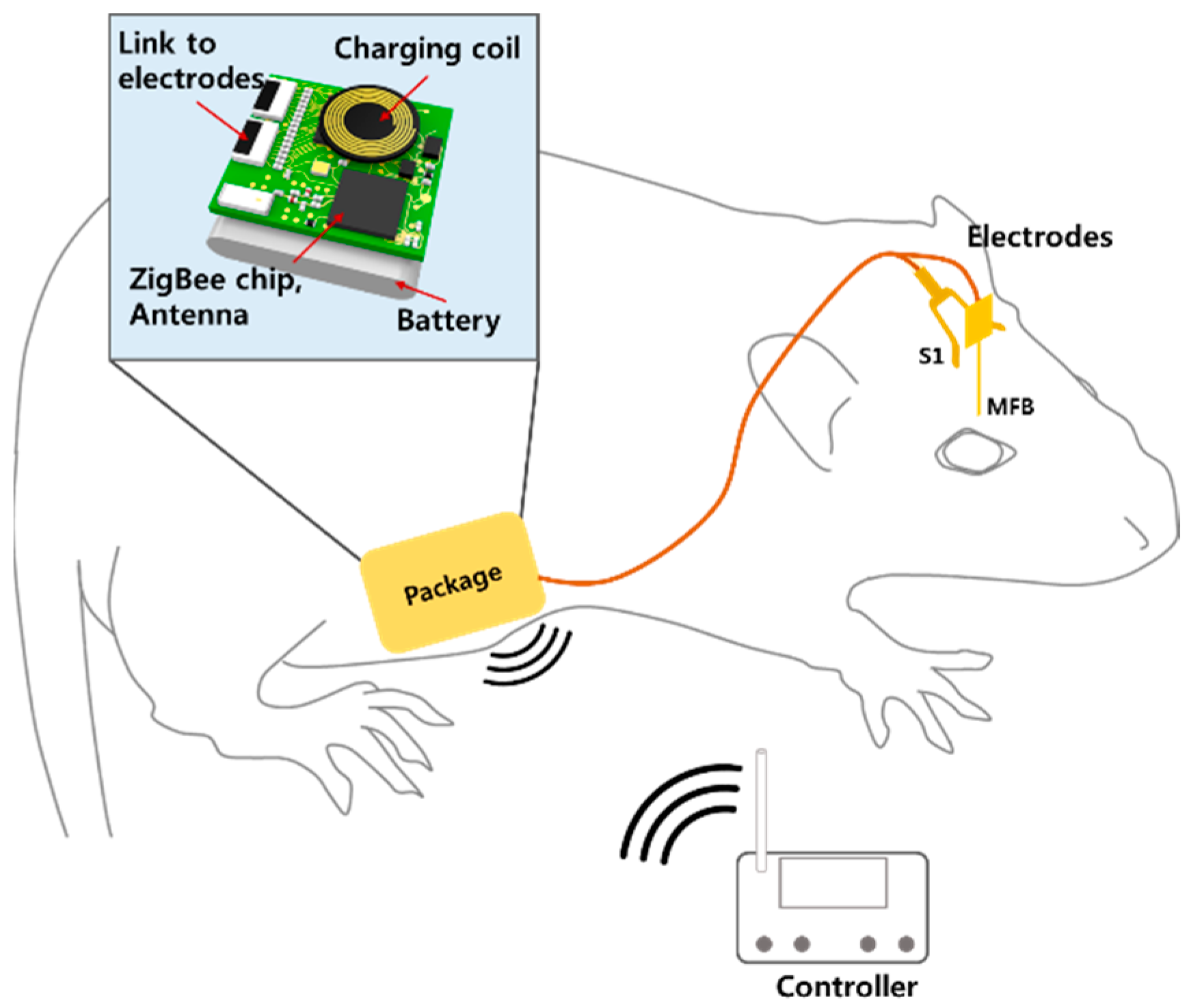
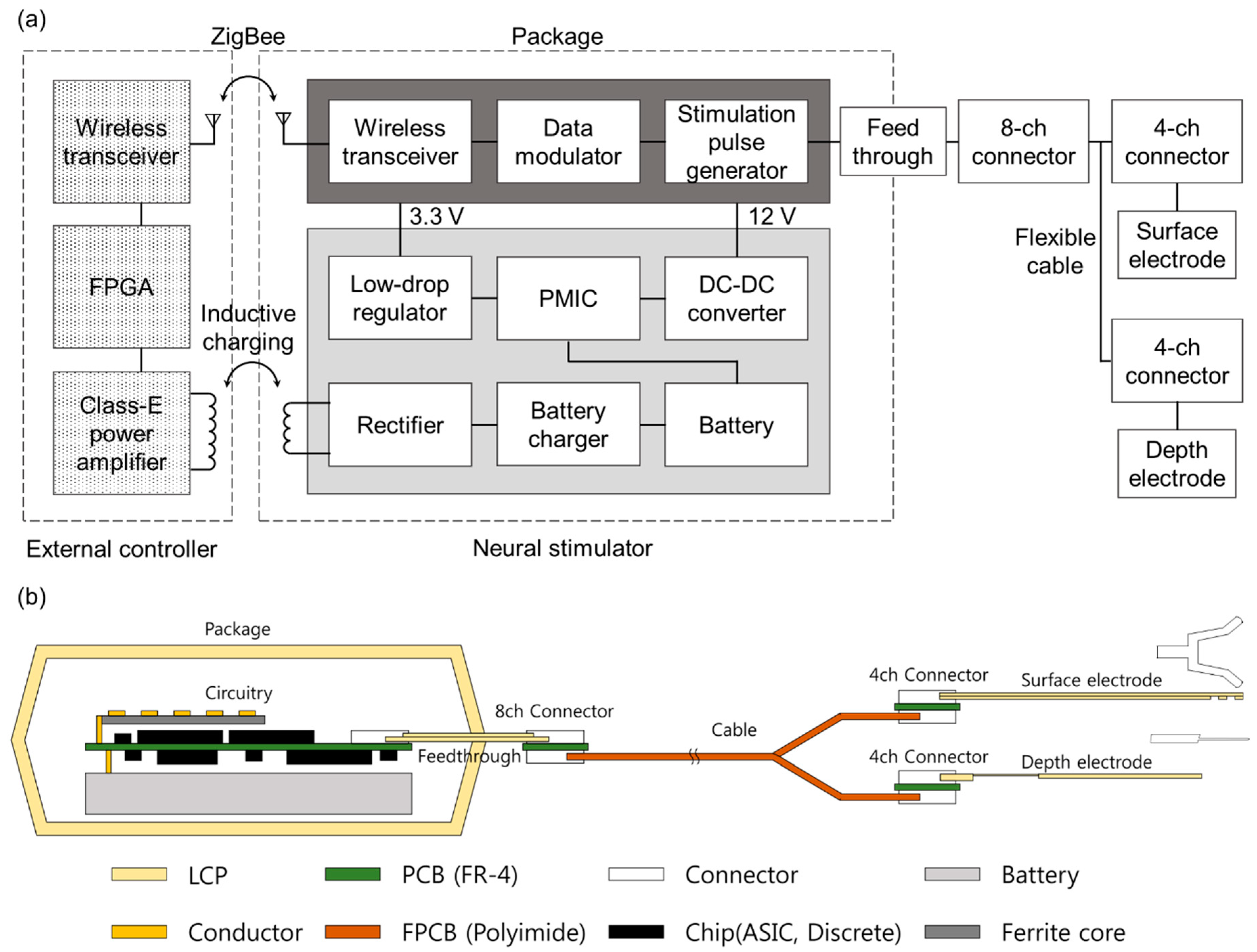
2.1. System Overview
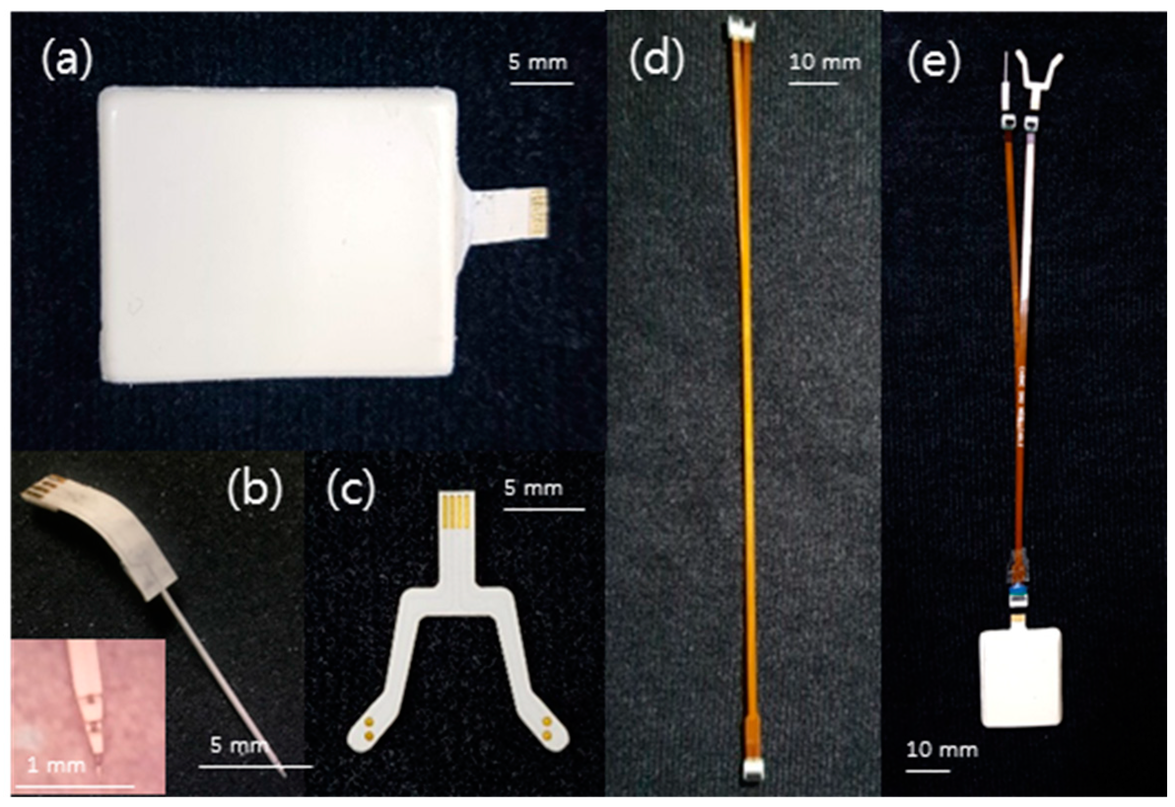
The cortical stimulating system consists of an implanted stimulator and an external controller which are wirelessly connected in two ways: ZigBee communication for stimulation control and a 2.5 MHz inductive link for intermittent battery recharging, as shown in Figure 2.
The implanted stimulator unit was assembled by independently created modular parts of electronics package, two types of cortical electrode arrays, connectors and cables. In the electronics package, a ZigBee-compliant RF transceiver (CC2530, Texas Instruments, Dallas, TX, USA) receives the stimulation parameters (channel configuration, pulse amplitude, pulse width, and pulse rate) and on/off commands from the external controller. The received data is pulse-width modulated before being fed into an application-specific integrated circuit (ASIC) that generates biphasic current pulses with the desired parameters and channel configuration. The transceiver is specially programmed for minimized power consumption by alternating between active mode and sleep mode at durations of 100 and 10 ms, respectively. The communication capability is deactivated in sleep mode, reducing the power consumption to nearly a tenth of that when it is continuous working. The cost is a latency time of communications of up to 110 ms, which is in the acceptable range for this animal behavioral test considering that the transceiver module consumes the most power (~96% of the total standby power) among all components in the system. The average delay between the command initiation (button push) and the pulse generation is about 60 ms, which is the half the cycle of two alternating power modes plus approximately 5 ms of RF communication delay. The implanted stimulator is powered by a 3.7 V lithium battery (TW302020, The Han, Seoul, Korea) embedded in the package for untethered animal experiments; this battery can be wirelessly charged via an inductive link at 2.5 MHz. The charging and discharging processes of the battery are regulated by a power management IC (BQ25505, Texas Instruments). The implanted electronics were encapsulated by an LCP package with a microfabricated feedthrough protruding from the package for interconnections with electrode arrays via customized cables and connectors, as illustrated in Figure 2b.
The stimulating electrode array has two parts: a four-channel surface-type array and a four-channel depth-type array for accessing the primary somatosensory cortex (S1) and the MFB, respectively. The Y-shaped surface electrode has two arms that can target the left and the right somatosensory cortices, each with two electrodes for bipolar stimulation. The depth-type array has four electrode sites linearly positioned at the tip of the shank with a spacing of 0.25 mm, two of which can adaptively be paired for precisely targeted bipolar stimulation of the MFB to evoke a sense of reward [31].
The external controller implemented on a printed circuit board (PCB) includes the same ZigBee transceiver chip for sending the command data into the stimulator, and a class-E amplifier for driving the external coil, both of the which are controlled by a custom programmed field-programmable gate array (FPGA; SPARTAN3A, Xilinx, CA, USA). The stimulation “on” command and the adjustment of stimulation can both be completed using buttons on the board in real time.

2.2. Fabrication

Both of the electrode arrays were microfabricated using LCP films generally following the procedures in previous publications on LCP-based neural interfaces [31,32]. Briefly, a gold layer was photolithographically patterned on a 25 μm-thick LCP substrate (Vecstar CT-Z series, Kuraray, Tokyo, Japan) by evaporation and electroplating; it was then encapsulated with a 25 μm-thick lower melting point cover LCP film (Vecstar CT-F series, Kuraray, Japan) by thermal bonding using a heating press (model 4330; Carver, USA). The exposure of the electrode sites and connection pads, and the outlining process were performed by laser-machining using a UV laser system (Samurai System, DPSS, CA, USA). Finally, iridium oxide (IrOx) was electroplated onto the electrode sites to improve the electrochemical characteristics. The fabrication of the depth-type electrode only differs from the above process for the surface array in that four sheets of metal-patterned LCP films were laminated with a cover layer as well as additional padding layers to reach a total thickness of 250 μm to ensure suitable mechanical strength of the shank during implantation into the cortex. All parts of the depth probe that are not inserted into cortex were thinned down to 100 μm by means of laser ablation for greater flexibility.
The LCP-based 8-channel feedthrough board, 4.5 mm by 10 mm in size, provides an electrical bridge between inside and outside of the LCP package, or stimulating circuit and electrode arrays, respectively. It was microfabricated through a similar process of patterning, insulation, and laser-machining of LCP films to have eight gold tracks running between the exposed pad areas at both ends. The flexible ribbon cables used were custom made from a polyimide substrate by a manufacturer of flexible PCBs. The 4ch/8ch connectors interconnecting the feedthrough, flex cable, and the arrays were fabricated by mounting two commercial flexible flat cable (FFC)/flexible printed circuit board (FPCB) connectors on FR-4 PCB (4 × 6 mm2).
All electronic components, the ASIC, the battery and a power-receiving coil (760308101208A, Wurth Electronics Inc., Niedernhall, Germany) for wireless communication, stimulation pulse generation, and power management were mounted on a four-layer FR-4 PCB of 20 mm × 18 mm in size. The assembled stimulator board with the feedthrough board plugged into an onboard connector was placed between two 500 μm-thick three-dimensionally deformed LCP films. This was followed by thermal pressing on the perimeter of the package with a 1.5 mm margin for biocompatible encapsulation of the electronics to protect them from body fluids. The top and bottom LCP films for the package were prepared by the thermal bonding and deformation of five 100 μm-thick LCP films into the desired nonplanar shape using a pair of aluminum jigs at 295 °C for 10 min with a load of 2 Kg/cm2. The edge of the package was trimmed by a laser and smoothened by applying small amount of dental cement.

2.3. Bench Top Evaluation

The functionality of the device was evaluated in a bench top setting with regard to three aspects: electrochemical impedance spectroscopy (EIS), wireless control of the pulse generation, and a battery charging test.
The EIS of the stimulating electrode arrays was measured using a potentiostat (SI 1287/Si1260, Solatron, Leicestershire, UK) for frequencies ranging from 1 Hz to 100 kHz by applying sinusoidal waves with an amplitude of 10 mV in a phosphate-buffered solution (PBS; 1×, Gibco, New York USA).
A voltage transient of the electrode triggered by the external controller was measured in a PBS solution while the pulse parameters and operation distances were varied. The stimulator ASIC was designed to generate a burst of 50 biphasic current pulses per stimulation. The pulse parameters of the pulse rate, pulse duration, and amplitude can be varied through the wireless ZigBee communication to deliver 17 bit stimulation instructions into the package. The test was conducted using a fully assembled stimulator and electrode array but without packaging to have the access to the voltage nodes for measurement. Additionally, the signal-to-noise ratio (SNR) of the ZigBee communication link between the controller and the LCP-encapsulated stimulator was evaluated. The received signal strength indicator (RSSI) of the background noise and the received packets was used to calculate the SNR. The measurement was performed in an open space while varying the communication distances and directions.
The amount of power delivered during the charging session depending on the coil distance was assessed using an identical stimulator, but the active parts of the electronics were replaced by their equivalent loads. While the onboard transceiver alternates between sleep mode and active mode, corresponding equivalent loads were used to measure the amount of received power at varying coil distances.

2.4. In Vivo Evaluation

2.4.1. Animal Care

Three male adult Sprague–Dawley rats (200–250 g) (Orientbiod, Osan, Korea) were individually housed in polycarbonate cages with wood chip bedding while free access to food and water was allowed. A 12 h light/dark cycle (08:00 to 20:00) was maintained at 24 ± 2° and 55 ± 5% humidity. The Institutional Animal Care and Use Committee of Yonsei University (IACUC no. 2016-0161, date of approval 26 September 2016) approved the study, which minimized the number of animals.

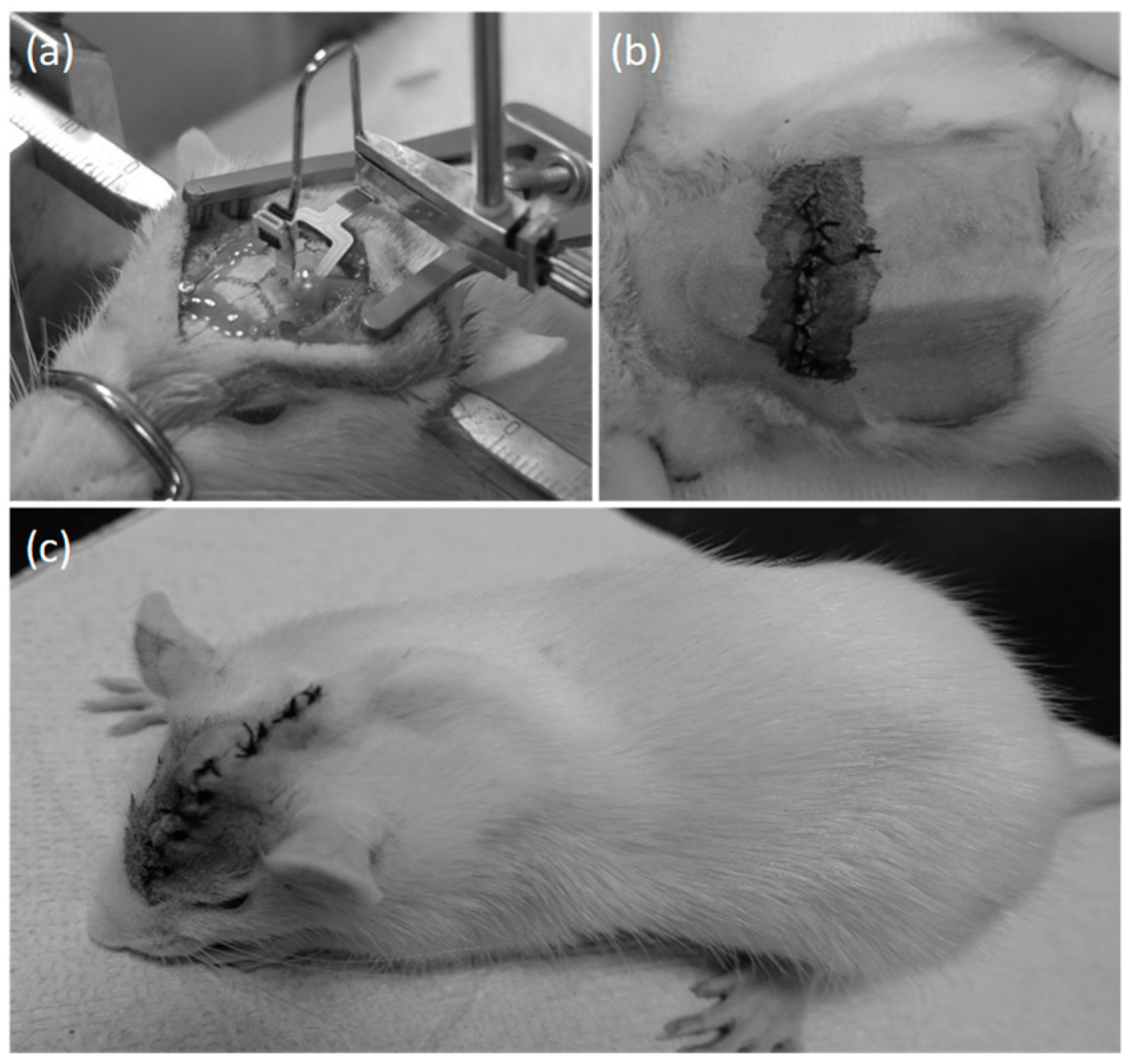
2.4.2. Surgical Procedure

Rats were anesthetized via an intraperitoneal injection of pentobarbital (40 mg/kg) (Hanlim Pharm, Seoul, Korea) and positioned in a stereotaxic frame. The rats were injected with 0.1 mL of atropine (Huons, Sungnam, Korea) 10 min before the injection to insure the stability of anesthesia. The midline of the scalp was incised, and the surface of skull was scraped. Three small burr holes to anchor the screws were drilled into the skull (AP +4.0 mm, ML ±3.0 mm; and AP −7.0 mm, ML +4.0 mm). Screws (tip diameter 1.0 mm) were inserted into the holes.
One burr hole for positioning the depth of the electrode to stimulate the MFB was drilled (AP −2.3 mm, ML −1.8 mm), and two parallelogram-shaped skull sections were removed to position the surface electrode to stimulate the barrel field (approximately AP −2.0 mm, ML −5.0 mm). Caution was taken to avoid penetrating the dura mater. The surface electrode was positioned through the parallelogram-shaped hole and fixed with dental resin to facilitate the positioning of the electrode. The depth electrode (AP −2.3, ML −1.8 mm) was vertically lowered (DV 8.6 mm, [4]) using a micromanipulator (SA-25A, Narishige, Tokyo, Japan) and fixed with dental resin. Two electrode arrays were plugged into two 4-channel connectors and cables, followed by the application of dental resin around the connectors for encapsulation. The cables were threaded to the subcutaneous pocket at the abdominal skin via a subcutaneous tunnel that was created from the neck to the abdomen. The flexible cable and the feedthrough of the package were connected by the 8-channel connector. After connection of the cables to the package, dental resin was applied to the connector to secure the sealing. The package was placed in the subcutaneous pocket. The wounds were closed with sutures and the stimulation test commenced three days thereafter.

2.4.3. Wired Test for Determination of the Stimulus Parameters

Prior to the in vivo evaluation, a set of wired stimulation tests was performed using the same electrode array that was wire-connected to a stimulator circuit board identical to the wireless stimulator. This was done to find the optimized implantation location and to tailor the stimulation parameters of both the surface array and the depth array to induce directional movement by eliciting a virtual touch sense via S1 and to evoke a reward sense at the MFB region, respectively.
For both the MFB and S1 stimulation and for both the wired and wireless experiments, a single stimulus consists of a burst of 50 charge-balanced biphasic current pulses. The stimulus is produced when one of the three stimulation buttons (S1 left, S1 right, and MFB) on the external controller is pressed.
For the MFB stimulation, rats (n = 3) implanted with two arrays were placed in a Skinner box with a lever which triggers electrical stimulation on the MFB when pressed [33]. The MFB stimulation was given as a reward only when the rat voluntarily pushed the lever without operator’s intervention such that the rat could learn to correlate the lever push and the compensation stimuli [33]. The number of lever pushes per minute was observed depending on the amplitude of the current pulses while the pulse rate and duration were fixed at 250 Hz and 0.2 ms, respectively, based on results from the literature [4,5].
For the S1 area to control the directional changes of the locomotion of the rat, electrical stimulation was applied to the right S1 as a virtual touch sensation of the left whisker, causing the rat to turn to the right, while stimulation was given to the left S1 to make it turn to the left [34,35]. The proper range of the stimulation amplitude that stably evoked visually observable behavioral responses was determined to be a fixed pulse rate and duration of 0.5 ms and 180 Hz, respectively [4,5].

2.4.4. Wireless Stimulation and Training

After full implantation of the whole system, rats (n = 3) were trained for movement control in two phases through which they learned to correlate the directional cue given as the virtual somatosensory touch sense at S1 to the MFB reward. First, the rats learned to obtain an MFB reward by moving forward and turning toward the correct direction following the left- or right-turning cues in open space. A custom-built remote controller was used to deliver the stimulation parameters and the onset command wirelessly for both S1 and MFB in real time. After this initial training phase, the rats were subsequently placed in a 3D maze consisting of a 30-degree ramp, a 45-degree ramp, a square maze, an obstacle and a tower cave maze. The rat was navigated through the designated path in the maze using a combination of directional cues and rewards.

2.4.5. Control Test

Control experiments were conducted to rule out any possibility of animal behaviors induced by environmental factors such as the clicking of the button on the remote controller as opposed to the electrical stimulation applied to the cortex. To do this, during the wireless experimental setup, rat behavior was observed when (1) S1 stimulation was given without a subsequent MFB reward, (2) MFB stimulation was applied alone, and (3) the simulation buttons were pressed with the remote controller turned off.

3. Results

3.1. Fabrication

The fabricated fully implantable neural stimulator is shown in Figure 3. A rectangular LCP package (29 mm × 26 mm × 8 mm size, 5.9 g weight) encasing the wireless stimulating circuit board was assembled with independently fabricated surface and depth electrode arrays via a feedthrough, connectors and cables. The Y-shaped surface array is 50 μm thick, while the shank of the depth-type electrode has a cross-section of 250 × 250 μm2. Using laser ablation, the middle part of the shank that needs to be bent after implantation was thinned down to a thickness of 100 μm for greater flexibility.

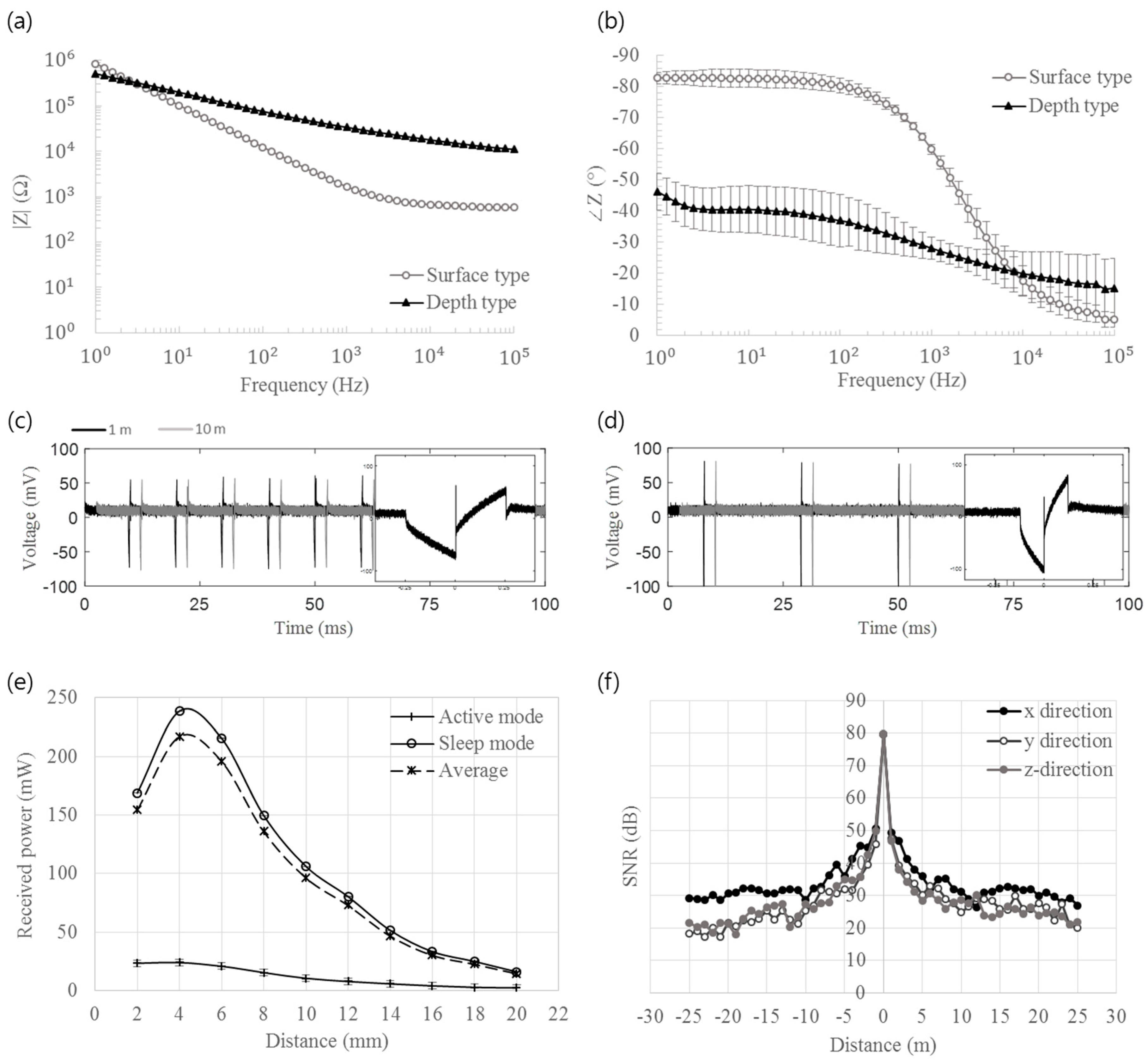
3.2. Bench Top Evaluation

The means and the standard deviations of the EIS measurements are plotted in Figure 4 for the magnitude (a) and phase (b) at each frequency in the range from 0.1 Hz to 100 kHz. The average impedance magnitude of the surface-type and depth-type electrodes with the IrOx deposition were 1.67 ± 0.387 kΩ and 33.6 ± 24.7 kΩ each at 1 kHz, respectively.
In a stimulation pulsing test with wireless control, the stimulator could generate biphasic current pulses with varying pulse parameters in accordance with the incoming data from the external controller. The representative waveforms of the output pulses are shown in Figure 4c,d for corresponding pulse rates, pulse durations, and amplitudes of (c) 100 Hz, 500 μs, 1 mA, and (d) 50 Hz, 250 μs, and 2 mA. The adjustable ranges of the stimulation parameters are 0.01 to 10.23 mA for the pulse amplitude, 10 to 630 µs for the pulse duration, and 20 to 226 Hz for the pulse rate. The stimulator could generate pulses up to a distance of approximately 10 m between the stimulator and the external remote controller. The produced pulses maintained the desired parameters throughout the operation range before abruptly disappearing at the maximum distance.
The calculated equivalent load was 120 Ω in active mode and 3.08 kΩ in sleep mode. The measured amount of power received by each load value is shown in Figure 4e, along with the time-weighted (100 ms for sleep mode and 10 ms for active mode) average power, which peaked at 217 mW at 4 mm. The received power in the sleep mode was higher than that in the active mode. This is assumed to be due to the higher equivalent load resistance in the sleep mode that resulted in the higher power transfer efficiency of the inductive link [36,37]. The maximum power transfer at a separation distance of 4 mm is the result of the external coil tuned to match the mutual inductance at an intercoil distance of 3 to 5 mm, which is the most typical range for charging of this stimulator in rats.
Figure 4f shows the measured SNR of the ZigBee telemetry depending on the distance between the stimulator and the external controller on three orthogonal axes. The SNR values were averaged after four repetitions for each point. The SNR was observed to decrease below 30 dB at a distance greater than approximately 10 m for all three directions, in good agreement with a previous study reporting that ZigBee can maintain reliable communications when the SNR is higher than 25 dB [38].

3.3. In Vivo Evaluation

3.3.1. Wired Test for Determination of the Stimulus Parameters

Figure 5a shows a rat in a Skinner box while electrical stimulation to the MFB is being triggered when the rat presses the lever. The number of times the lever is pressed per minute was recorded as a function of the increasing current amplitude of the stimulation pulses to the MFB, as shown in Figure 5b. Greater strength of the stimulation induced the rats to push the lever more frequently, but with a decreasing slope. Based on this observation, we chose 200 to 400 μA as the stimulation intensity levels for the following wireless experiment, as these values fall in a range comparable to that in a previous report [4]. As described earlier, the pulse frequency and the pulse width were fixed at 250 Hz and 0.2 ms, respectively, where a burst of 50 pulses constituted a single stimulus.
In the case of wired S1 stimulation, the behavioral responses of rats were observed while varying the pulse amplitude with a fixed pulse width of 0.5 ms and pulse duration of 180 Hz. Here, we chose the appropriate amplitude range of 100 to 350 μA, which could elicit consistent and natural turning behavior of the rats while not causing the rats to twitch or jerk due to an excessively strong stimulation. This is also in good agreement with the results from previous publications [4,5].

3.3.2. Wireless Test in Freely Moving Condition

Figure 6a shows the surgical implantation of the stimulator by implanting the depth probes into MFB and the surface array into barrel cortex. After placing the package in the abdomen, as shown in Figure 6b, all of the modules were interconnected by connectors and cables. Subsequently, we closed the wound, as shown in Figure 6c.
First, the rats were trained to turn left or right in response to a combination of the stimulus on S1 as a directional cue and a subsequent MFB stimulus as a reward for a correct response. Figure 7a shows the behavioral response of the rat over the course of one second. The rat with the implanted stimulator turned left following the virtual sensation on the right whisker that was elicited by left S1 stimulation. The external remote controller is also shown in Figure 7a with the stimulation button pressed between t = 0.2 to 0.4 s. Similarly, the stimulation could induce the rat in this case to turn right, as shown in Figure 7b. The full movie can be found in Supplementary Materials.
After conditioning, the rat was remotely controlled to navigate through a 3D maze (Figure 7c and Supplementary Materials). We could induce the rats to climb a 30-degree ramp, enter a square maze, and return to the original point after travelling through rectangular corridor while making four turns. Despite some lingering behaviors, two rats could complete the task without failing to follow the induced direction. One rat was not trained, as it showed unexpected response to the MFB stimulation, presumably due to the depth electrode inserted deeper than intended, which stimulated the nigrostriatal pathway.

3.3.3. Control Group

A control test was conducted to confirm that the cortical stimulation indeed induced behavioral changes of the rat. When the S1 stimulus was applied without a subsequent MFB reward, the rat turned toward the correct direction, implying that the S1 stimulus alone is sufficient to induce movement of the rat after the conditioning process. When the MFB stimulus was applied, the rat showed a probing response, such as rapid vertical movement of the head [39] without any effective turning behavior. The rats did not respond to the clicking sound of the stimulation buttons on the remote controller.

4. Discussion

Here, we described the development and evaluation of a fully implantable neural stimulator to remotely control the movement of unrestrained rats. Full implantation of the device was achieved by modular design and LCP packaging that could contribute to miniaturization of the implant. The key technologies developed for this device, including a microelectrode array, stimulation circuit, wireless powering/telemetry, integration/packaging, electrophysiology, and animal experiments, can be readily extended and utilized for a much wider range of implantable neural interfaces, such as those used in deep-brain stimulation (DBS) and spinal cord stimulations for a brain–machine interface (BMI) and for other sensory and motor prosthetics. The device may be also applied for accessing locations where humans or mechanical robots cannot reach. Examples of these cases are a nuclear disaster, a collapsed building due to a natural disaster, and land mine searches.
While the current system was utilized only for stimulation in this paper, this system can be easily extended to recording applications as the system structure has a lot in common with the recording devices, including wireless communication, neural electrode arrays, and packaging technology. The recording function can be readily implemented by three minor modifications: addition of an amplifier, reprogramming of the RF transceiver, and tuning of the electrode array. An amplifier chip is required to match the amplitude of the recorded signal to the input range of the analog–digital converter (ADC) included in the ZigBee transceiver chip. The RF transceiver needs to be programmed to include an uplink communication for sending out the acquired neural data to the external controller which then can be sent to a computer for data collection and storage. Lastly, the stimulating arrays can be turned into recording arrays after redesign of the electrode size and material for appropriate electrochemical characteristics but using the same fabrication process.
The package part of the implanted stimulator is 29 mm long, 26 mm wide, and 8 mm thick with a maximum operation time of 13 h after full charging. The main bottleneck limiting miniaturization is the battery, which was chosen as a result of a compromise between the size and operating time. Therefore, the package can be miniaturized further if either the energy density of the battery is improved or the power consumption of the system is reduced. Given that the RF communication module consumes the most energy in this proposed system, we devised a special power-saving scheme which automatically alternates between an active mode and a sleep mode, which could reduce the power consumption by a factor of 10. Considering that this system is mostly in an idle state, except for button-pressing moments that would not occur more than twice per second, further power reductions are possible. For example, ZigBee with full performance supports a data rate of 250 kbps, while this application requires 448 bps at most, assuming that two events, at most, occur every second. Ideally, power consumption can be reduced to five-hundredths of the original value given that ZigBee power consumption is proportional to the data rate. The device could be also miniaturized if a monolithic fabrication technique of LCP [30] is applied here by integrating and packaging all of the components in a homogeneous LCP substrate and covering them with a conformable structure fitting the target tissue or organ.
The implantation site of the package was also an issue when designing the device and the experiments. We explored the feasibility of package implantation in both the back and abdominal space. A relatively large space is available in the back, but dummy devices implanted in the back hindered the movement of the spine by applying constant mechanical stress to the spine and surrounding tissues. When the package was implanted underneath the abdominal skin, it was much easier for the rat to move around. Nevertheless, we acknowledge that the organs in the abdomen are very delicate and can be affected by breathing, moving, or sleeping motions. We attempted to minimize the discomfort of the rat by sophisticatedly customizing of the system based on the rat anatomy, including the cable length, electrode shape, the surgical procedure, and by minimizing the package size in our hardware specifications.
Long-term reliability is an important issue for the implantable device, but we could not perform a long-term study due to some issues during in vivo experiments. Although the entire system was designed for the minimized discomfort of the rats, they sometimes showed signs of discomfort, such as scratching the sutured area, which resulted in the exposure of the implanted package in the worst case. We judged that at this stage, it would be a more ethical and viable option to verify the feasibility of remote control of the rat movements with fully implanted stimulator as a proof-of-concept demonstration with the current version of the device and the surgical procedures. Therefore, the in vivo experiment was conducted for a single day during which the stimulation to S1 and MFB induced consistent and stable responses of the rats. Given there is a lot of room for further miniaturization of the electronics package, our next device is expected to be readily applied in the chronic experiments of the remote control of rat movement by means of the smaller package size as well as the choice of implantation site of the package that causes minimized discomfort of the rats.
The bottleneck of our approach toward the long-term in vivo test was the animal reaction to the implantation, rather than the long-term reliability of the stimulator electronics and package. The long-term reliability of the LCP encapsulation, including LCP-based electrode arrays and LCP packaging of electronics, has been demonstrated in the previous studies. These studies suggested that the lifetime of LCP encapsulation, including all the possible water penetration paths, e.g., LCP–LCP adhesion, LCP–metal adhesion, and LCP surface permeation, is estimated to be at least a few years at body temperature [40,41,42,43,44,45,46]. The only interface that has not been addressed in the previous studies is the 4ch/8ch connectors sealed by dental cement. Accordingly, we evaluated the reliability of the connector part by soaking the connectors with flex cable sealed by dental cement in 27 °C PBS while the cable ends were held above the water level for measurement. The resistance between each channel in the cable and the Pt reference electrode in PBS was monitored over time as shown in Figure S1. The resistance values decreased from ~4.52 ± 1.02 to 0.711 ± 0.580 MΩ in 21 days after the soaking. While the result suggests the connector sealed by dental cement can be useful for semi-chronic tests for a few weeks, we acknowledge that the connector part is the weakest point in the entire system in terms of hermeticity. One aspect of our ongoing work is the development of long-term reliable cable connectors based on monolithic LCP fabrication, which can be also applied to general modularly designed biomedical implants.
We are also seeking an alternative power source to replace the battery in the package as it limits the operation time and also limits device miniaturization. Rapidly evolving energy harvesting technologies, such piezoelectricity, thermoelectricity, or biofuel cells, could be adopted as a means of self-powering of the implanted device. Energy harvesting for implantable devices has been pioneered in several publications [47,48,49,50], though the power output levels remain below those needed for practical applications.

5. Conclusions

A remotely controlled, fully implantable neural stimulator for small animals was developed and evaluated in vivo. The system consists of a surface-type array for stimulating the S1 cortex for virtual sensation, a depth array for stimulating the MFB as a reward, a package encasing the stimulation electronics, and a ZigBee communication module, all of which were integrated on an LCP substrate. The stimulation parameters were optimized in a wired configuration with rats, followed by remote control of rat movement by means of the full implantation of the wireless stimulator. The device could successfully induce the rats to turn left or right and thus navigate through a 3D maze.

Supplementary Materials

The following are available online at https://www.mdpi.com/2079-9292/8/6/706/s1.

Author Contributions

Conceptualization, S.Y., J.S. (Jungmin Seo) and S.J.K.; methodology, S.Y., C.S.K., J.S. (Jungmin Seo), G.J.C., S.-H.A. and S.S.; validation, S.Y., C.S.K., J.S. (Jungmin Seo), G.J.C. and S.-H.A.; formal analysis, S.Y.; investigation, S.Y., J.S. (Jungmin Seo) and J.S. (Jaewoo Shin); writing—original draft preparation, S.Y. and C.S.K.; writing—review and editing, S.Y., J.J. and S.J.K.; visualization, S.Y. and C.S.K.; supervision, H.H.J., J.W.C. and S.J.K.; project administration, S.J.K.; funding acquisition, S.J.K.

Funding

This work was supported by the CABMC through funding by the Defense Acquisition Program Administration (UD170030ID) of Korea.

Conflicts of Interest

The authors declare no conflicts of interest.

References

  1. Birbaumer, N. Slow cortical potentials: Plasticity, operant control, and behavioral effects. Neuroscientist 1999, 5, 74–78. [Google Scholar] [CrossRef]
  2. Di Lazzaro, V.; Pilato, F.; Oliviero, A.; Dileone, M.; Saturno, E.; Mazzone, P.; Insola, A.; Profice, P.; Ranieri, F.; Capone, F.; et al. Origin of facilitation of motor-evoked potentials after paired magnetic stimulation: Direct recording of epidural activity in conscious humans. J. Neurophysiol. 2006, 96, 1765–1771. [Google Scholar] [CrossRef] [PubMed]
  3. Engel, A.K.; Moll, C.K.; Fried, I.; Ojemann, G.A. Invasive recordings from the human brain: Clinical insights and beyond. Nat. Rev. Neurosci. 2005, 6, 35–47. [Google Scholar] [CrossRef] [PubMed]
  4. Lee, M.-G.; Jun, G.; Choi, H.-S.; Jang, H.S.; Bae, Y.C.; Suk, K.; Jang, I.-S.; Choi, B.-J. Operant conditioning of rat navigation using electrical stimulation for directional cues and rewards. Behav. Process. 2010, 84, 715–720. [Google Scholar] [CrossRef] [PubMed]
  5. Talwar, S.K.; Xu, S.; Hawley, E.S.; Weiss, S.A.; Moxon, K.A.; Chapin, J.K. Behavioural neuroscience: Rat navigation guided by remote control. Nature 2002, 417, 37–38. [Google Scholar] [CrossRef] [PubMed]
  6. Hiremath, S.V.; Tyler-Kabara, E.C.; Wheeler, J.J.; Moran, D.W.; Gaunt, R.A.; Collinger, J.L.; Foldes, S.T.; Weber, D.J.; Chen, W.; Boninger, M.L.; et al. Human perception of electrical stimulation on the surface of somatosensory cortex. PLoS ONE 2017, 12, e0176020. [Google Scholar] [CrossRef] [PubMed]
  7. Libet, B.; Alberts, W.W.; Wright, E.; Delattre, L.; Levin, G.; Feinstein, B. Production of threshold levels of conscious sensation by electrical stimulation of human somatosensory cortex. In Neurophysiology of Consciousness; Springer: Boston, MA, USA, 1993; pp. 1–34. [Google Scholar]
  8. Romo, R.; Hernández, A.; Zainos, A.; Brody, C.D.; Lemus, L. Sensing without touching: Psychophysical performance based on cortical microstimulation. Neuron 2000, 26, 273–278. [Google Scholar] [CrossRef]
  9. Wickersham, I.; Groh, J.M. Neurophysiology: Electrically evoking sensory experience. Curr. Biol. 1998, 8, R412–R414. [Google Scholar] [CrossRef] [Green Version]
  10. Gratton, A.; Hoffer, B.J.; Gerhardt, G.A. Effects of electrical stimulation of brain reward sites on release of dopamine in rat: An in vivo electrochemical study. Brain Res. Bull. 1988, 21, 319–324. [Google Scholar] [CrossRef]
  11. Hermer-Vazquez, L.; Hermer-Vazquez, R.; Rybinnik, I.; Greebel, G.; Keller, R.; Xu, S.; Chapin, J.K. Rapid learning and flexible memory in “habit” tasks in rats trained with brain stimulation reward. Physiol. Behav. 2005, 84, 753–759. [Google Scholar] [CrossRef]
  12. Kuhr, W.G.; Wightman, R.M.; Rebec, G.V. Dopaminergic neurons: Simultaneous measurements of dopamine release and single-unit activity during stimulation of the medial forebrain bundle. Brain Res. 1987, 418, 122–128. [Google Scholar] [CrossRef]
  13. Adkins-Muir, D.L.; Jones, T.A. Cortical electrical stimulation combined with rehabilitative training: Enhanced functional recovery and dendritic plasticity following focal cortical ischemia in rats. Neurol. Res. 2003, 25, 780–788. [Google Scholar] [CrossRef] [PubMed]
  14. Berényi, A.; Belluscio, M.; Mao, D.; Buzsáki, G. Closed-loop control of epilepsy by transcranial electrical stimulation. Science 2012, 337, 735–737. [Google Scholar] [CrossRef] [PubMed]
  15. Calancie, B.; Harris, W.; Broton, J.G.; Alexeeva, N.; Green, B.A. “Threshold-level” multipulse transcranial electrical stimulation of motor cortex for intraoperative monitoring of spinal motor tracts: Description of method and comparison to somatosensory evoked potential monitoring. J. Neurosurg. 1998, 88, 457–470. [Google Scholar] [CrossRef] [PubMed]
  16. Kozák, G.; Földi, T.; Berényi, A. Chronic Transcranial Electrical Stimulation and Intracortical Recording in Rats. JOVE (J. Vis. Exp.) 2018, 135, e56669. [Google Scholar] [CrossRef] [PubMed]
  17. Matsuyama, N.; Uwano, T.; Hori, E.; Ono, T.; Nishijo, H. Reward contingency modulates neuronal activity in rat septal nuclei during elemental and configural association tasks. Front. Behav. Neurosci. 2011, 5, 26. [Google Scholar] [CrossRef] [PubMed]
  18. Chen, X.; Xu, K.; Ye, S.; Guo, S.; Zheng, X. A remote constant current stimulator designed for rat-robot navigation. In Proceedings of the 2013 35th Annual International Conference of the IEEE Engineering in Medicine and Biology Society (EMBC), Osaka, Japan, 3–7 July 2013; pp. 2168–2171. [Google Scholar]
  19. Xu, S.; Talwar, S.K.; Hawley, E.S.; Li, L.; Chapin, J.K. A multi-channel telemetry system for brain microstimulation in freely roaming animals. J. Neurosci. Methods 2004, 133, 57–63. [Google Scholar] [CrossRef]
  20. Yang, J.; Huai, R.; Wang, H.; Lv, C.; Su, X. A robo-pigeon based on an innovative multi-mode telestimulation system. Bio-Med. Mater. Eng. 2015, 26, S357–S363. [Google Scholar] [CrossRef] [Green Version]
  21. Ye, X.; Wang, P.; Liu, J.; Zhang, S.; Jiang, J.; Wang, Q.; Chen, W.; Zheng, X. A portable telemetry system for brain stimulation and neuronal activity recording in freely behaving small animals. J. Neurosci. Methods 2008, 174, 186–193. [Google Scholar] [CrossRef]
  22. Millard, R.E.; Shepherd, R.K. A fully implantable stimulator for use in small laboratory animals. J. Neurosci. Methods 2007, 166, 168–177. [Google Scholar] [CrossRef] [Green Version]
  23. Perry, D.; Grayden, D.; Shepherd, R.; Fallon, J. A fully implantable rodent neural stimulator. J. Neural Eng. 2012, 9, 014001. [Google Scholar] [CrossRef] [PubMed]
  24. Baker, N. ZigBee and Bluetooth: Strengths and weaknesses for industrial applications. Comput. Control Eng. 2005, 16, 20–25. [Google Scholar] [CrossRef]
  25. Fadlullah, Z.M.; Fouda, M.M.; Kato, N.; Takeuchi, A.; Iwasaki, N.; Nozaki, Y. Toward intelligent machine-to-machine communications in smart grid. IEEE Commun. Mag. 2011, 49, 60–65. [Google Scholar] [CrossRef]
  26. Kinney, P. Zigbee technology: Wireless control that simply works. In Proceedings of the Communications Design Conference, San Jose, CA, USA, 30 September–2 October 2003; pp. 1–7. [Google Scholar]
  27. Lee, J.-S.; Su, Y.-W.; Shen, C.-C. A comparative study of wireless protocols: Bluetooth, UWB, ZigBee, and Wi-Fi. Ind. Electron. Soc. 2007, 5, 46–51. [Google Scholar]
  28. Rosello, V.; Portilla, J.; Riesgo, T. Ultra low power FPGA-based architecture for wake-up radio in wireless sensor networks. In Proceedings of the IECON 2011-37th Annual Conference of the IEEE Industrial Electronics Society, Melbourne, Australia, 7–10 November 2011; pp. 3826–3831. [Google Scholar]
  29. Qin, Y.; Howlader, M.M.; Deen, M.J.; Haddara, Y.M.; Selvaganapathy, P.R. Polymer integration for packaging of implantable sensors. Sens. Actuators B Chem. 2014, 202, 758–778. [Google Scholar] [CrossRef]
  30. Jeong, J.; Bae, S.H.; Min, K.S.; Seo, J.-M.; Chung, H.; Kim, S.J. A miniaturized, eye-conformable, and long-term reliable retinal prosthesis using monolithic fabrication of liquid crystal polymer (LCP). IEEE Trans. Biomed. Eng. 2015, 62, 982–989. [Google Scholar] [CrossRef] [PubMed]
  31. Shin, S.; Kim, J.; Jeong, J.; Gwon, T.M.; Choi, G.J.; Lee, S.E.; Kim, J.; Jun, S.B.; Chang, J.W.; Kim, S.J. High charge storage capacity electrodeposited iridium oxide film on liquid crystal polymer-based neural electrodes. Sens. Mater. 2016, 28, 243–260. [Google Scholar]
  32. Seo, J.; Wee, J.H.; Park, J.H.; Park, P.; Kim, J.-W.; Kim, S.J. Nerve cuff electrode using embedded magnets and its application to hypoglossal nerve stimulation. J. Neural Eng. 2016, 13, 066014. [Google Scholar] [CrossRef]
  33. Feng, Z.; Chen, W.; Ye, X.; Zhang, S.; Zheng, X.; Wang, P.; Jiang, J.; Jin, L.; Xu, Z.; Liu, C.; et al. A remote control training system for rat navigation in complicated environment. J. Zhejiang Univ. Sci. A 2007, 8, 323–330. [Google Scholar] [CrossRef]
  34. Bosman, L.W.; Houweling, A.R.; Owens, C.B.; Tanke, N.; Shevchouk, O.T.; Rahmati, N.; Teunissen, W.H.; Ju, C.; Gong, W.; Koekkoek, S.K.; et al. Anatomical pathways involved in generating and sensing rhythmic whisker movements. Front. Integr. Neurosci. 2011, 5, 53. [Google Scholar] [CrossRef]
  35. Cho, Y.K.; Kim, S.; Jung, H.H.; Chang, J.W.; Kim, Y.-J.; Shin, H.-C.; Jun, S.B. Neuromodulation methods for animal locomotion control. Biomed. Eng. Lett. 2016, 6, 134–147. [Google Scholar] [CrossRef]
  36. Harrison, R.R. Designing efficient inductive power links for implantable devices. In Proceedings of the 2007 IEEE International Symposium on Circuits and Systems, New Orleans, LA, USA, 27–30 May 2007; pp. 2080–2083. [Google Scholar]
  37. Silay, K.M.; Dondi, D.; Larcher, L.; Declercq, M.; Benini, L.; Leblebici, Y.; Dehollain, C. Load optimization of an inductive power link for remote powering of biomedical implants. In Proceedings of the 2009 IEEE International Symposium on Circuits and Systems, Taipei, Taiwan, 24–27 May 2009; pp. 533–536. [Google Scholar]
  38. Ciampa, M. CWNA Guide to Wireless LANs; Cengage Learning: Boston, MA, USA, 2012. [Google Scholar]
  39. Moran, T.H.; Schwartz, G.J.; Blass, E.M. Organized behavioral responses to lateral hypothalamic electrical stimulation in infant rats. J. Neurosci. 1983, 3, 10–19. [Google Scholar] [CrossRef] [PubMed] [Green Version]
  40. Hwang, G.-T.; Im, D.; Lee, S.E.; Lee, J.; Koo, M.; Park, S.Y.; Kim, S.; Yang, K.; Kim, S.J.; Lee, K.; et al. In vivo silicon-based flexible radio frequency integrated circuits monolithically encapsulated with biocompatible liquid crystal polymers. ACS Nano 2013, 7, 4545–4553. [Google Scholar] [CrossRef] [PubMed]
  41. Jeong, J.; Bae, S.H.; Seo, J.-M.; Chung, H.; Kim, S.J. Long-term evaluation of a liquid crystal polymer (LCP)-based retinal prosthesis. J. Neural Eng. 2016, 13, 025004. [Google Scholar] [CrossRef] [PubMed]
  42. Zhou, J.; Woo, S.J.; Park, S.; Kim, E.; Seo, J.; Chung, H.; Kim, S. A suprachoroidal electrical retinal stimulator design for long-term animal experiments and in vivo assessment of its feasibility and biocompatibility in rabbits. BioMed Res. Int. 2008, 2008, 547428. [Google Scholar] [CrossRef] [PubMed]
  43. Cheung, K.C.; Renaud, P.; Tanila, H.; Djupsund, K. Flexible polyimide microelectrode array for in vivo recordings and current source density analysis. Biosens. Bioelectron. 2007, 22, 1783–1790. [Google Scholar] [CrossRef] [PubMed] [Green Version]
  44. Lee, S.W.; Seo, J.-M.; Ha, S.; Kim, E.T.; Chung, H.; Kim, S.J. Development of microelectrode arrays for artificial retinal implants using liquid crystal polymers. Investig. Ophthalmol. Vis. Sci. 2009, 50, 5859–5866. [Google Scholar] [CrossRef]
  45. Woods, V.; Trumpis, M.; Bent, B.; Palopoli-Trojani, K.; Chiang, C.-H.; Wang, C.; Yu, C.; Insanally, M.N.; Froemke, R.C.; Viventi, J. Long-term recording reliability of liquid crystal polymer µECoG arrays. J. Neural Eng. 2018, 15, 066024. [Google Scholar] [CrossRef]
  46. Lee, S.W.; Min, K.S.; Jeong, J.; Kim, J.; Kim, S.J. Monolithic encapsulation of implantable neuroprosthetic devices using liquid crystal polymers. IEEE Trans. Biomed. Eng. 2011, 58, 2255–2263. [Google Scholar]
  47. Hannan, M.A.; Mutashar, S.; Samad, S.A.; Hussain, A. Energy harvesting for the implantable biomedical devices: Issues and challenges. Biomed. Eng. Online 2014, 13, 79. [Google Scholar] [CrossRef]
  48. Hwang, G.-T.; Kim, Y.; Lee, J.-H.; Oh, S.; Jeong, C.K.; Park, D.Y.; Ryu, J.; Kwon, H.; Lee, S.-G.; Joung, B.; et al. Self-powered deep brain stimulation via a flexible PIMNT energy harvester. Energy Environ. Sci. 2015, 8, 2677–2684. [Google Scholar] [CrossRef]
  49. Olivo, J.; Carrara, S.; De Micheli, G. Energy harvesting and remote powering for implantable biosensors. IEEE Sens. J. 2011, 11, 1573–1586. [Google Scholar] [CrossRef]
  50. Zebda, A.; Cosnier, S.; Alcaraz, J.-P.; Holzinger, M.; Le Goff, A.; Gondran, C.; Boucher, F.; Giroud, F.; Gorgy, K.; Lamraoui, H. Single glucose biofuel cells implanted in rats power electronic devices. Sci. Rep. 2013, 3, 1516. [Google Scholar] [CrossRef] [PubMed]
Figure 1. A fully implantable neural stimulator: a surface array for primary sensory cortex (S1) stimulation, a depth array for medial forebrain bundle (MFB) stimulation, a package encasing the stimulating electronics and wireless module to produce stimulation pulses by means of wireless control from an external controller.
Electronics 08 00706 g001
Figure 2. (a) Block diagram of the neural stimulator and the external controller, and (b) cross-sectional illustration of the proposed stimulator.
Electronics 08 00706 g002
Figure 3. Independently fabricated modules of the neural stimulator: (a) package; (b) depth-type electrode array (inset: tip of the shank); (c) surface-type electrode array; (d) cable and connectors, and (e) assembled whole device.
Electronics 08 00706 g003
Figure 4. EIS measurements of the two types of fabricated electrode arrays: (a) magnitude and (b) phase, (c,d) biphasic stimulation pulses measured in phosphate-buffered solution (PBS) with the various parameters by the remote controller at distances of 1 and 10 m: (c) at pulse rates, pulse durations, and amplitudes of 100 Hz, 500 μs, 50 μA and (d) 50 Hz, 250 μs, and 100 μA, respectively (inset shows the magnified view of a biphasic pulse); (e) power received by the stimulator circuit as a function of the coil separation distance for both the active mode and sleep mode, and (f) averaged SNR for ZigBee communication depending on the distance between the stimulator and the external controller in three directions.
Electronics 08 00706 g004
Figure 5. (a) A rat in a Skinner box during the wired test for the determination of the stimulus parameters; an MFB stimulation is triggered by lever pressing, and (b) number of lever presses versus the MFB stimulation amplitude.
Electronics 08 00706 g005
Figure 6. Surgical implantation of a neural stimulator in a rat: (a) electrodes inserted in the brain; (b) package implanted in underneath the abdominal skin, and (c) a rat after surgery.
Electronics 08 00706 g006
Figure 7. Wireless control of the movement of a rat: rats were induced to turn to the left (a) or right (b) following directional cues from the remote ZigBee-based controller, showing the movement in a 3D maze, and (c) returning to the origin after travelling through a rectangular corridor (drawing at the left bottom corner indicates the current position of the rat in the map of the maze).
Electronics 08 00706 g007
Table 1. Comparison of functionalities and performance capabilities of prior researches and this work. Our device is characterized by full implantation, low power consumption, and wireless telemetry. LCP: liquid crystal polymer.
[19][21][18][20][22][23]This Work
Size (mm3)48 × 23 × 1936 × 22 × 7.532 × 25 × 626 × 16 × 914 × 12 × 6N/A29 × 26 × 8
Weight (g)28402092.5N/A5.9
PackagingNoneNoneNoneNoneSiliconeSilicone/ParyleneLCP
Stimulation ElectrodeStainless steel wireStainless steel wireUnknownStainless steel wirePt electrode array, Pt/Ir wiresPt electrode array, Pt/Ir wiresMicrofabricated LCP array
Stimulation MethodConstant voltageConstant voltage/currentConstant currentConstant voltageConstant currentConstant currentConstant current
Stimulation TargetMFB, S1MFB, S1dlPAG, S1, VTAPAG, DIVACochleaCochleaMFB, S1
ConfigurationHead-mounted, percutaneous connectionHead-mounted, percutaneous connectionHead-mounted, percutaneous connectionHead-mounted, percutaneous connection,Fully implanted, monolithicFully implanted, monolithicFully implanted, Modular
CommunicationFMBluetoothBluetoothFSKN/A2.4 GHz radio linkZigBee
PoweringLi battery (160 mAh)Li battery (120 mAh × 2)Li battery (80 mAh)Li battery (120 mAh)3-axis Inductive coils on cage3-axis Inductive coils on cageLi battery (90 mAh), Inductive charging
Avg. Power Consumption (Calculated)82.5 mW222 mW148 mW51.8 mWN/AN/A15.2 mW
Target AnimalLong–Evans ratSprague–Dawley ratSprague–Dawley ratPigeonMouse, ratHooded Wistar ratSprague–Dawley rat

