Article

Decision-Making System for Lane Change Using Deep Reinforcement Learning in Connected and Automated Driving

Department of Electronics and Computer Engineering, Hanyang University, Seoul 133-791, Korea
*
Author to whom correspondence should be addressed.
Electronics 2019, 8(5), 543; https://doi.org/10.3390/electronics8050543
Submission received: 4 April 2019 / Revised: 7 May 2019 / Accepted: 10 May 2019 / Published: 14 May 2019
(This article belongs to the Special Issue Intelligent Transportation Systems (ITS))

Abstract

:
Lane changing systems have consistently received attention in the fields of vehicular communication and autonomous vehicles. In this paper, we propose a lane change system that combines deep reinforcement learning and vehicular communication. A host vehicle, trying to change lanes, receives the state information of the host vehicle and a remote vehicle that are both equipped with vehicular communication devices. A deep deterministic policy gradient learning algorithm in the host vehicle determines the high-level action of the host vehicle from the state information. The proposed system learns straight-line driving and collision avoidance actions without vehicle dynamics knowledge. Finally, we consider the update period for the state information from the host and remote vehicles.

1. Introduction

Lane change systems have been studied for a long time in the research on autonomous driving [1,2], as well as vehicular communication [3,4,5,6]. Lane change systems are continuously drawing attention from academia and industry and several solutions have been proposed to solve this challenging problem. Vehicular communication-based methods can be divided into Long Term Evolution-based [7] or IEEE 802.11p-based method [8]. Moreover, there have been many studies on lane change systems for connected and automated vehicle (CAVs), which combines autonomous driving and vehicular communication [9].
There have been many advances in autonomous vehicle systems in recent years. In particular, end-to-end learning has been proposed, which is a new paradigm that includes perception and decision-making [10]. The traditional method for autonomous navigation is to recognize the environment based on sensor data, generate a future trajectory through decision-making and planning modules, and then follow the given path through control. However, end-to-end learning integrates perception, decision-making, and planning based on machine learning, and produces a control input directly from sensor information [10].
Deep reinforcement learning (DRL) is a combination of deep learning and reinforcement learning. Reinforcement learning involves learning how to map situations to actions to maximize a numerical reward signal [11]. The combination of reinforcement learning and deep learning, which relies on powerful function approximation and representation learning properties, provides a powerful tool [12]. In addition, deep reinforcement learning allows a vehicle agent to learn from its own behavior instead of labeled data [13]. No labeled data are required in an environment in which the vehicle agent will take actions and obtain rewards.
Deep reinforcement learning could be applied to various domains. A typical example is Atari video games. In recent years, a deep Q network (DQN) is a representative example of deep reinforcement learning that shows human-level performance in Atari video games [14]. A DQN has the advantage of learning directly from high-dimension image pixels. It can also be used for indoor navigation [15] and control policies [16] for specific purposes in the robotics field.
Many studies on autonomous driving using deep reinforcement learning have been conducted. Wang et al. [17] suggested a deep reinforcement learning architecture for the on-ramp merging of autonomous vehicles. It features the use of a long short-term memory (LSTM) model for the historical driving information. Wang et al. [18] subsequently proposed automated maneuvers for lane change. The authors considered continuous action space but did not take into account the lateral control issue. Another study was conducted on autonomous driving decision-making [19]. A DQN was used to determine the speed and lane change action of the autonomous vehicle agent. Kaushik et al. [20] developed overtaking maneuvers using deep reinforcement learning. An important feature of this system is the application of curriculum learning. This method, which simulates the way humans and animals learn, enables the effective learning of the vehicle agent. Mukadam et al. [21] suggested decision-making for lane changing in a multi-agent setting. The authors dealt with discrete action space, but it might weaken the feasibility of the solution when applied to real-world problems [18]. In addition, the SUMO simulator was used for evaluation. In this simulator, vehicles run only along the center lane, and the lane change is performed like a teleport. It has a limitation that lateral control cannot be considered as with Reference [18]. Mirchevska et al. [22] proposed a formal verification method to overcome the limits of machine learning in lane change and the authors also defined action space as discrete.
We propose a decision-making system for connected and automated vehicle during lane change. The purpose of our system is to find a policy represented from an actor network, μ , as seen in Figure 1. The actor network, μ , takes the current state of the host vehicle and the remote vehicle from sensors and gives the high-level outputs (throttle, steering wheel). Then the actor network passes the high-level outputs to a controller of the host vehicle. We constructed a simulation environment for autonomous vehicles where an agent can perform trial-and-error simulations.
Our contributions are as follows:
  • A model that combines deep reinforcement learning with vehicular communication is proposed. We show how to utilize information from a remote vehicle as well as the host vehicle in deep reinforcement learning.
  • We handle different state information update periods for the host and remote vehicles. Generally, the state information of the remote vehicle is updated every 100 ms via vehicle communication, whereas the state information of the host vehicle is updated faster. This paper shows the results of agent learning considering these different update periods.
  • We handle continuous action space for steering wheel and accelerator to improve the feasibility of the lane change problem. Furthermore, in order that our end-to-end method covers collision-free action, reward function takes the collision reward directly into account.
  • We introduce a physically and visually realistic simulator Airsim [23]. Our main focus is to avoid collision between vehicles and realistic longitudinal and lateral control. We have experimented in the simulation environment that can handle both controls.
The remainder of our paper considers the following. Section 2 shows the lane change system architecture and how the agent learns. Section 3 presents the simulation environment for training and evaluation, along with the agent learning results. Finally, the conclusions are presented in Section 4.

2. Decision-Making System for Lane Change

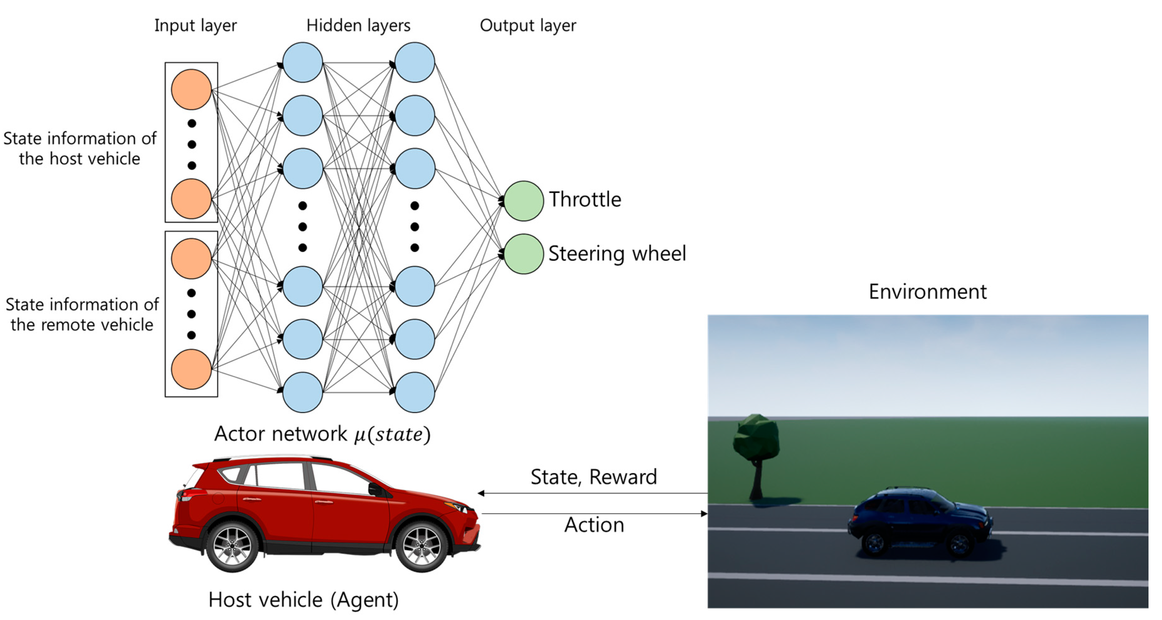
2.1. System Architecture

The architecture of the proposed system consists of the host vehicle (agent) and environment. Just as the agent learns from the environment through interaction in reinforcement learning (RL), the host vehicle interacts with the environment, including the remote vehicle. First, the host vehicle receives the current state of the environment and determines an action that affects the environment. Then, the host vehicle takes the action and the environment gives the host vehicle a reward and the next state corresponding to the action.
More specifically, the host vehicle receives self-state information from the sensors mounted in the agent or state information from the remote vehicle through the vehicular communication device. The state information is provided to the trained actor neural network. The actions needed for a collision-free lane change are generated. After the next time step, the host vehicle will receive a reward and the next set of state information. We designed a reward function that performs a lane change while avoiding collision with the remote vehicle.

2.2. Markov Decision Process

The reinforcement learning problem is defined in the form of a Markov decision process (MDP), which is made up of states, actions, transition dynamics, and rewards. In our system, we assume that the environment is fully observable. A detailed formulation is presented in the next subsection.

2.2.1. States

The host vehicle observes current state, s t , from the environment at time t. The host vehicle can acquire state information through sensors. A lane change not only relates to vehicle dynamics, but also depends on road geometry [18]. The state space includes speed and heading to handle the longitudinal and lateral dynamics of the host vehicle. The x, y coordinates of the host vehicle are included for road geometry. The information of the remote vehicle is contained for analyzing collision between vehicles. A set of states, S, in our system consists of eight elements. At timestep t, S = { s t 1 ,   s t 2 ,   s t 3 ,   s t 4 ,   s t 5 ,   s t 6 ,   s t 7 ,   s t 8 } .
  • s t 1 represents the x coordinate of the host vehicle.
  • s t 2 represents the y coordinate of the host vehicle.
  • s t 3 represents the speed of the host vehicle.
  • s t 4 represents the heading of the host vehicle.
  • s t 5 shows the x coordinate of the remote vehicle.
  • s t 6 shows the y coordinate of the remote vehicle.
  • s t 7 represents the speed of the remote vehicle.
  • s t 8 represents the heading of the remote vehicle.
The values of all elements are converted into values in the range of (0, 1) before being input to the neural network. s t 1 ,   s t 2 ,   s t 3 ,   s t 4 contain state information related to the host vehicle. Conversely, s t 5 ,   s t 6 ,   s t 7 ,   s t 8 are associated with the remote vehicle. In the training and evaluation stage, s t 1 ,   s t 2 ,   s t 3 ,   s t 4 are updated with a period of 0.01 s, and s t 5 ,   s t 6 ,   s t 7 ,   s t 8 are updated with a period of 0.1 s through vehicular communication.

2.2.2. Actions and Policy

The host vehicle takes actions in the current state. A set of actions, A , consists of 2 elements: A = { a t 1 ,   a t 2 } .
  • a t 1 represents the throttle of the host vehicle.
  • a t 2 represents the steering wheel of the host vehicle.
The goal of the host vehicle is to learn a policy π that maximizes the cumulative reward [12]. Generally, policy π is a probability function from the states: π : S p ( A = a | S ) . However, in our system, policy π is a function from states to actions (high-level control input). Given the current state values, the host vehicle can know the throttle and steering wheel values through the policy. In DRL, the policy is represented as a neural network.

2.2.3. Transition Dynamics

The transition dynamics is a function wherein the conditional probability of the next state S t + 1 is the probability of given state S t and action A t . One of the challenges in DRL is that there is no way for the host vehicle (agent) to know the transition dynamics. Therefore, the host vehicle (agent) learns by interacting with the environment. Namely, the host vehicle takes actions using the throttle and steering wheel, which allow it to influence the environment and obtain a reward. The host vehicle accumulates this information and uses it to learn the policy that ultimately maximizes the cumulative reward.

2.2.4. Rewards

The ultimate goal of the agent in DRL is to maximize the cumulative reward rather than the instant reward of the current state. It is important to design a reward function to induce the host vehicle to make the lane changes that we want.
We formulate a lane change task as an episodic task, which means it will end in a specific state [11]. Thus, we define a lane change task as moving into the next lane within a certain time without collision or leaving the road. To meet this goal, a reward function is constructed with three cases at each time step.
  • Collision with the remote vehicle and deviation from the road
    R ( t ) =   3 .
  • Final time step
    • Completion of the lane change
      R ( t ) =   1 .
    • Failure to complete the lane change
      R ( t ) =   0 .
  • Etc.
    • Driving in the next lane
      R ( t ) =   W n +   W s ×   V s .
    • Driving in the initial lane
      R ( t ) =   W i +   W s ×   V s .
    • Remainder
      R ( t ) =   W s ×   V s .
The first case is about penalization. If the host vehicle collides with the remote vehicle in the next lane or leaves the road, the reward is given as above, and the task is immediately terminated. The second case is about the success or failure of the lane change task in the final time step. The lane change is considered successful if the host vehicle is within 0.5 m of the next lane at a certain time step. Otherwise, it is a failure. The last case is about the driving process. This case determines most rewards in one episode. R ( t ) is the sum of the reward for the corresponding lane and the reward for the corresponding speed. First, the reward related to the lane is similar to the second case. If the host vehicle is within 0.5 m of the center of the lane, it receives the reward. The reward to be given related to the lane is as follows: W n in the next lane, W i in the initial lane, and 0 in the remainder. Second, the reward related to the velocity is expressed as the product of speed V s and weight W s . The advantage of DRL is that it can achieve the goal of the system without considering the vehicle dynamics of the host vehicle.

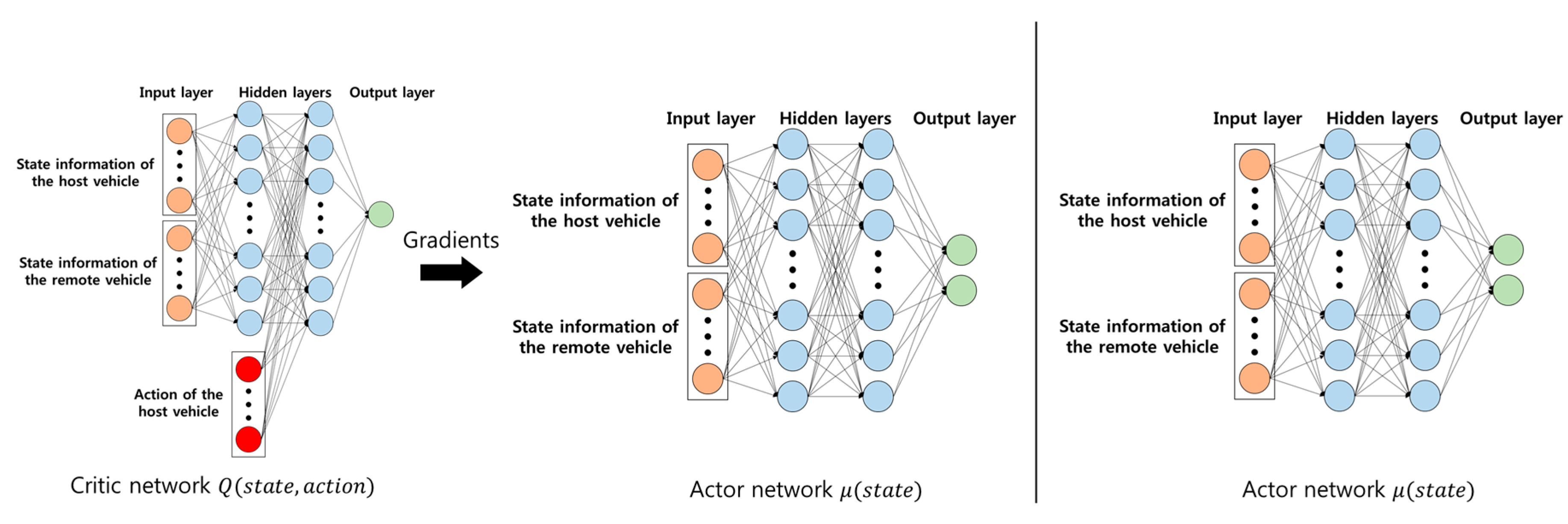
2.2.5. Deep Reinforcement Learning

We employed deep reinforcement learning. In our paper, the goal was to find an actor neural network, μ , for collision avoidance during lane change. We applied an actor–critic approach. Therefore, our decision-making system consisted of two neural networks: actor network, μ , and critic network, Q .
A critic Q ( s t , a t | θ Q ) is a neural network that estimates the cumulative reward taking state s t and action a t with weights θ Q in time step t. Equation (7) shows the feedforward of this critic network. It is used as a baseline for the actor network. The way is the same as deep-q-network (DQN) [14] in Equation (8) and Equation (9).
scalar   value = Q ( s t ,   a t | θ Q ) .
y t = R ( t ) + γ ×   Q ( s t + 1 ,   μ ( s t + 1 | θ μ ) | θ Q ) .
Q ( s t ,   a t | θ Q ) y t α × Q ( s t ,   a t | θ Q ) .
where α is the learning rate and y t is the sum of R ( t ) and Q ( s t + 1 , a t + 1 | θ Q ) with target network technique   Q and   μ .
An actor network is the central part in the proposed system. An actor μ ( s t | θ μ ) is also a neural network that produce action a t taking state s t with weights θ μ in Equation (10). Then, the actor will provide a high-level action to avoid collision. The actor μ ( s t | θ μ ) is updated through Equation (11) presented in the DDPG algorithm [24].
a t = μ ( s t | θ μ ) .
θ μ J 1 N i a Q ( s , a | θ Q ) | s = s i , a = μ ( s i ) θ μ μ ( s | θ μ ) | s i .
where N is minibatch size.
The characteristic of actor–critic method is that the networks used are different for training phase and testing phase. In training phase, the vehicle (agent) learns both actor and critic networks. The critic network is used to learn the actor network. However, in testing phase, the vehicle only uses actor networks in order to produce action. Figure 2 shows the neural networks used at each phase. The left figure relates to the training phase, and the right figure relates to the testing phase.

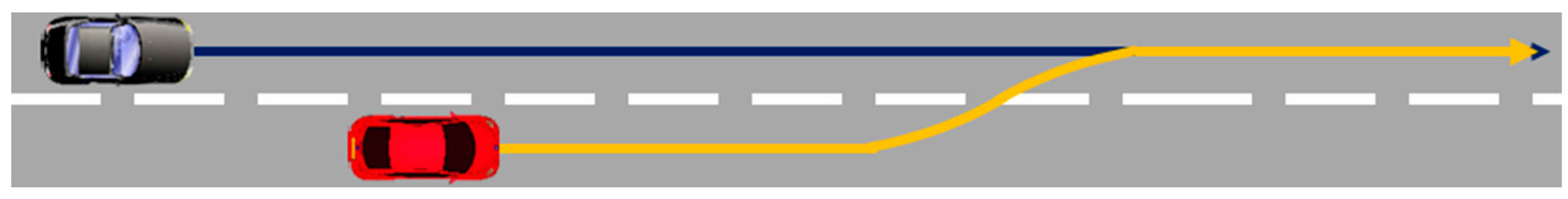
2.3. Training Scenario and Algorithm

The host vehicle learns a lane change scenario to avoid a collision on a straight road in Figure 3. The remote vehicle, a black car, is located in the next lane behind the host vehicle in initial state. Both vehicles have same initial speed V 0 . The remote vehicle makes a straight run and will run at a faster speed than the initial speed. The host vehicle tries to change lanes and control the speed.
We adopt the DDPG algorithm to allow the host vehicle to learn the lane change [24]. In order to use the DDPG algorithm, several assumptions and modification have been made. We need to use the experience replay memory technique [25] and the separate target network technique to apply the DDPG algorithm to our system. The reason for using the replay memory is to break the temporal correlations between consecutive samples by randomizing samples [12]. A time step was 0.01 s. It was assumed that there was no computation delay for the deep learning during the learning and evaluation. In autonomous driving, the control period is very short (milliseconds). Because of the computational delay during driving, the action was taken in a delayed state that was not the current state. Thus, during the learning and evaluation step, we ignored the computational delay by stopping the driving simulator. The states provided to the DDPG algorithm can be obtained from sensors. The state of the host vehicle is updated at each time step from the sensors of the host vehicle. The host vehicle can obtain the state of the remote vehicle through the vehicular communication device. Unlike the sensors of the host vehicle, it is assumed that the state of the remote vehicle is updated through a basic safety message, which allows it to be obtained every 10 time steps. Algorithm 1 shows the training algorithm with the assumptions and modifications mentioned above for the host vehicle.
Algorithm 1. Modification to Deep Deterministic Policy Gradient (DDPG) Training Algorithm.
Randomly initialize critic network and actor network
Initialize target networks and replay buffer
for episode = 1 to E do
Receive initial state from sensors in the host vehicle
for step = 0 to S-1 do
if step % 10 == 0 then
Receive state of the remote vehicle from the vehicular communication device
end if
Select action according to the current policy and exploration noise using normal distribution
Simulation pause off
Execute action and observe reward and observe new state
Simulation pause on
Store transition in replay memory
Sample a random minibatch of N transitions from replay memory
Update critic by minimizing the loss
Update the actor policy using the sampled policy gradient
Update the target networks
end for
end for

3. Experiments

3.1. Simulation Setup and Data Collection

Airsim was adopted to train the host vehicle to change lanes [23]. Airsim is an open source platform developed by Microsoft and used to reduce the gap between reality and simulation when developing autonomous vehicles. Airsim offers a variety of conveniences. Airsim is an Unreal Engine-based simulator. The Unreal Engine not only provides excellent visual rendering, but also provides rich functionality for collision-related experiments. When training a host vehicle by trial-and-error, it is possible for the host vehicle to directly experience collision states.
In order to train our neural network, we need to collect data from the environment. By driving the host vehicle and the remote vehicle in Airsim, we are able to collect the data necessary for learning. Airsim supports various sensors for vehicles. All vehicles are equipped with GPS and the Inertial Navigation System (INS). Through these sensors, we can collect desired vehicle status information.

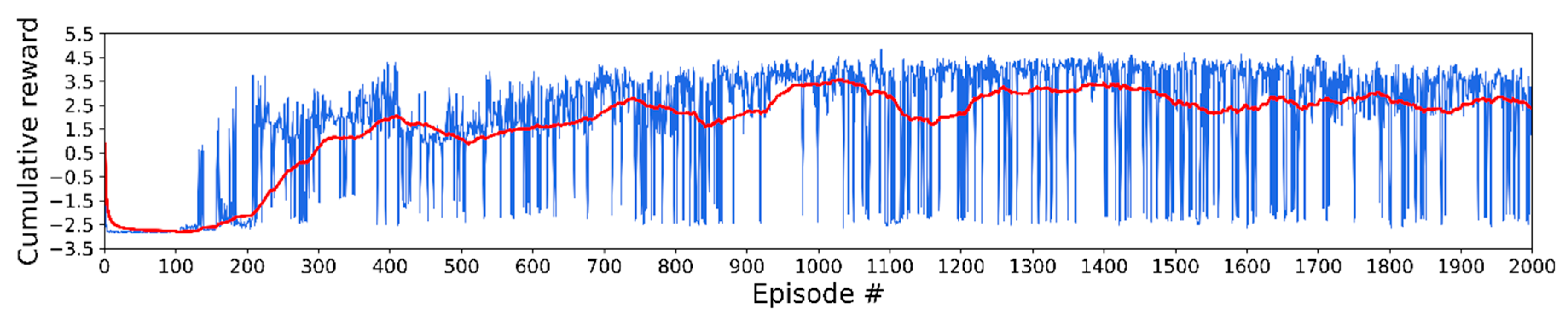
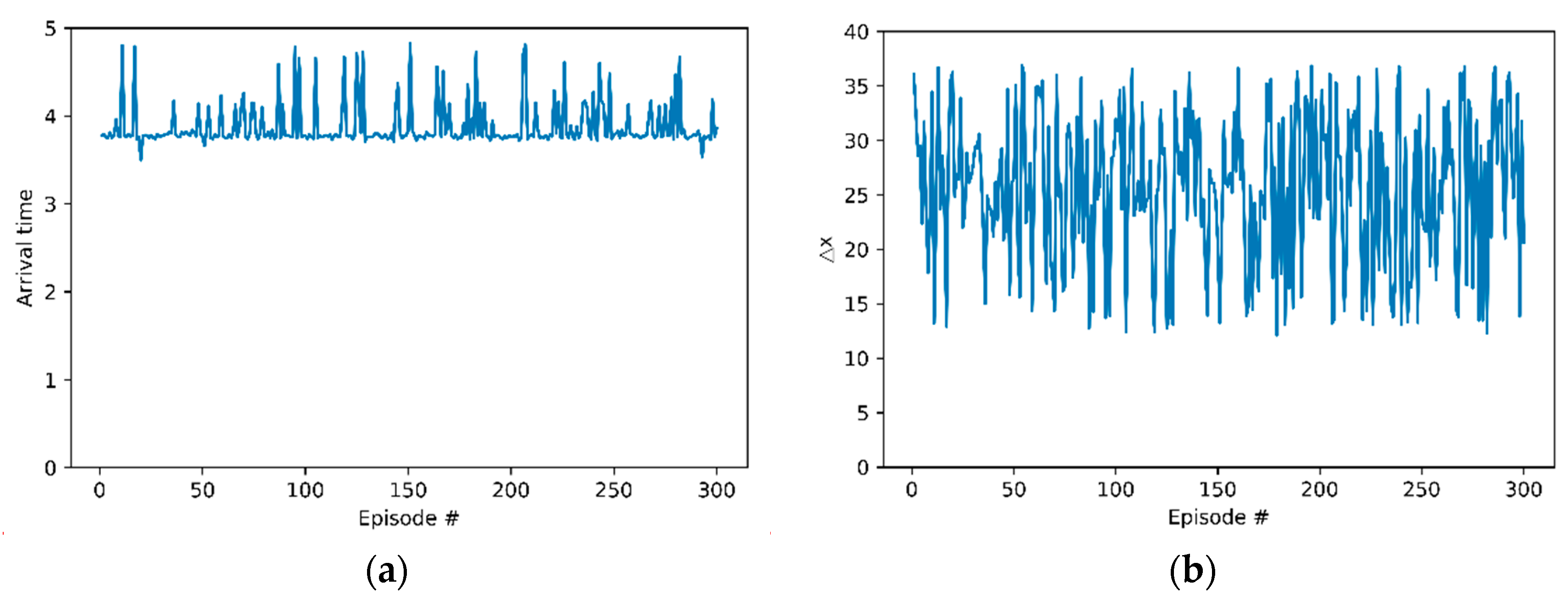
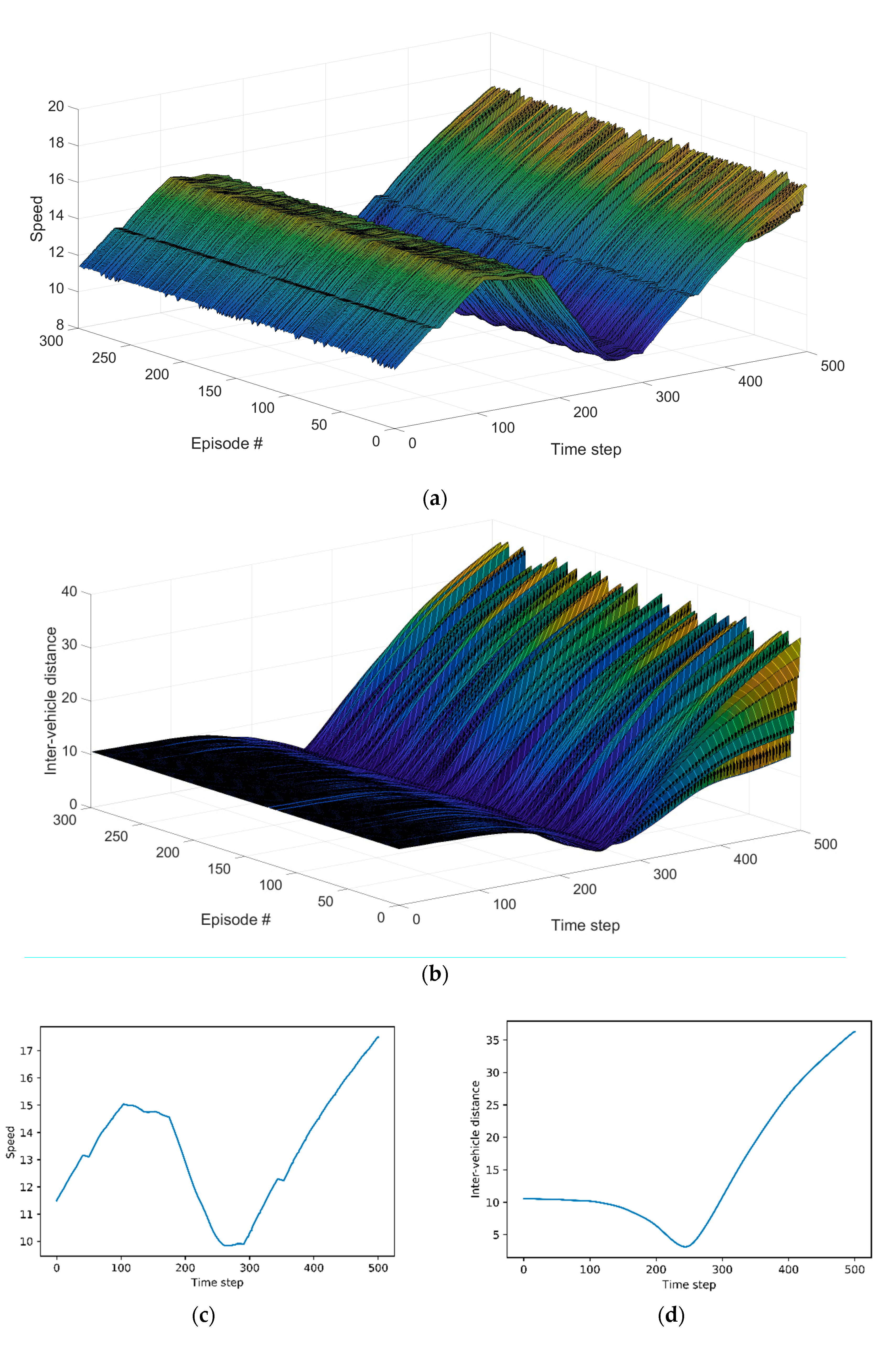
3.2. Training Details and Results

As shown in Figure 3, the host vehicle (red), remote vehicle (black), and straight road were constructed using the Unreal Engine. In the initial state of the training and evaluation, both the host vehicle and remote vehicle had initial speeds of V 0 , and the remote vehicle was located at distance d 0 behind the host vehicle in the next lane. After the initial state, the target speed of the remote vehicle was set uniformly in the range of [ V m i n ,   V m a x ] , and the remote vehicle constantly ran at the target speed.
The actor network consisted of two fully connected hidden layers with 64, 64 units. The critic network consisted of two fully connected hidden layers with 64, 64 + 2 (action size: throttle, acceleration) units. Figure 2 shows the architecture of actor network and critic network (left). All hidden layers in the actor network and the critic network used a rectified linear unit (ReLU) activation function. The output layer of the actor network has tanh activation function because of action space range. However, the output layer of the critic network does not have activation function. The weights of the output layer in both the actor network and critic network were initialized from a uniform distribution [ 3 × 10 3 , 3 × 10 3 ]. We use the Adam optimizer to update the actor network and the critic network. Table 1 lists parameters related to the road driving scenario and DDPG algorithm.
Figure 4 shows the cumulative reward (blue) per episode and average cumulative reward (red) in the training step. The cumulative reward is the sum of the rewards the host vehicle obtained from the reward function. The average cumulative reward is the average of only the most recent 100 scores. The lane change success rate was high from 850 to 1050 episodes. The highest average cumulative reward was 3.567 at 1028 episodes.

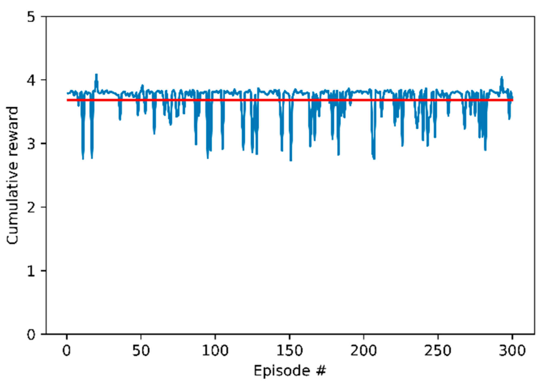
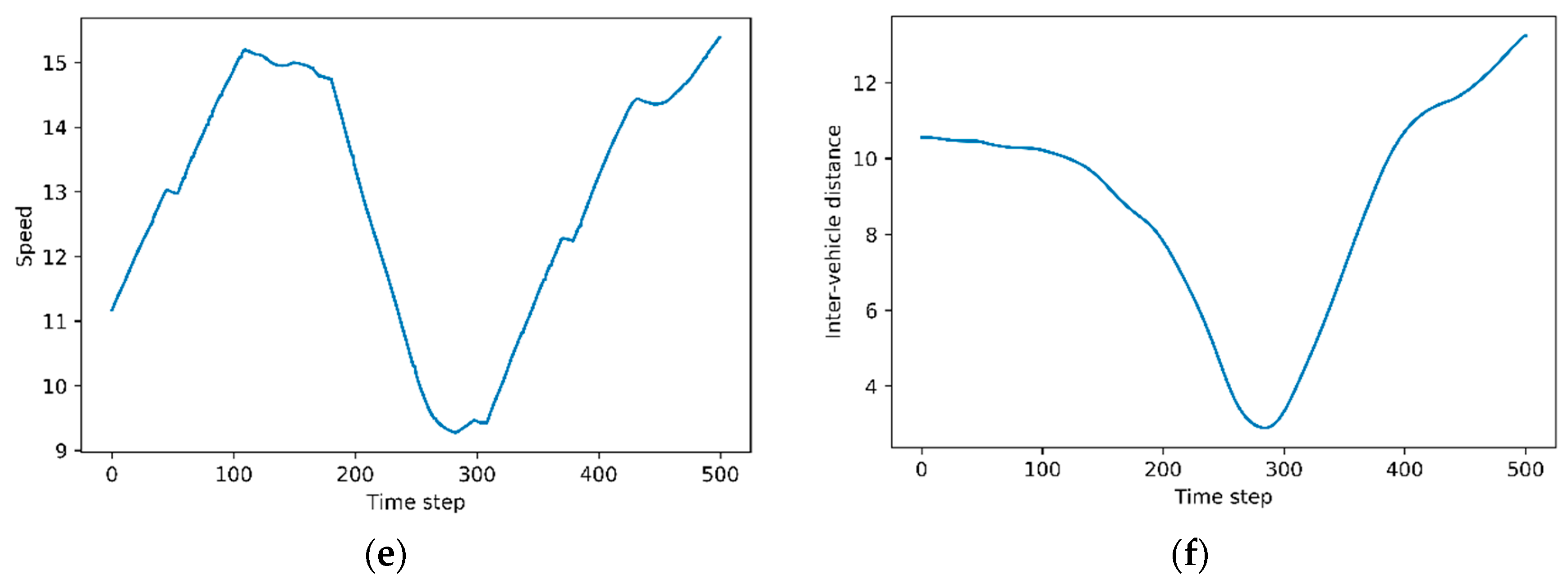
3.3. Evaluation Results

We evaluated the actor network, μ , after 2000 training episodes. We selected the weight to successfully perform the lane change and proceeded to the evaluation. We evaluated the weight of the 1028th episode, which had the highest average score. The lane change was successful, but the host vehicle did not reach a position within 0.5 m from the center of the next lane. We searched heuristically to find a weight that arrived close to the center with a successful lane change before and after the 1028th weight. As a result, the 1030th weight was found, which satisfied both conditions, and the evaluation was made with this weight. The evaluation was conducted in the same environment as the training stage, and a total of 300 episodes were performed. Figure 5 shows the result of the evaluation with the 1030th weight. Figure 5 shows the cumulative reward of the host vehicle. The average cumulative reward was 3.68 and is expressed in a red line. In all of the episodes, the host vehicle successfully performed the lane change without a collision with the remote vehicle.
To evaluate the performance of the host vehicle, three measures were introduced. We analyzed our decision-making system with three metrics. We obtained these measures as well as the cumulative reward for each episode.
First, the lane change success rate is the number of lane change successes divided by the total number of lane change trials. We defined the success of the lane changes as arrival in the next lane without collision with the remote vehicle and without leaving the road within a certain time. In Airsim, when a collision occurs between vehicles in simulation, it provides information about the collision. At each time step, the position of the host vehicle can be used to determine if it has left the road or it has arrived in the next lane. For termination of each episode, the result of the lane change was determined. The success rate was 1.0. In other words, the lane change in all episodes was made without collision.
Second, arrival time in next lane is the time when the host vehicle arrives in next lane. For every time step, the position of the host vehicle was checked and if the host vehicle was in next lane at first, the time step was recorded. Figure 6a shows arrival time. This indicates that the host vehicle has made a lane change within the max time step. The time the lane change occurred was before the end of every episode. In a training scenario, the remote vehicle departs from the rear of the host vehicle and passes through the host vehicle. The host vehicle learned that it made a lane change after the remote vehicle passed the host vehicle to avoid collision.
Difference between position x is the gap of position x between the host vehicle and the remote vehicle. The reason for defining this metric is to analyze the lane-change behavior of the host vehicle. When we set the coordinates axes, the x-axis value was designed to be larger in the longitudinal direction of both vehicles. Figure 6b shows the differences between the position x of the host vehicle subtracted from the position x of the remote vehicle. In every episode, the measurements were positive. The remote vehicle preceded the host vehicle at the end of lane change trials. The host vehicle showed a behavior pattern that it tried to change lanes after the remote vehicle had passed.
Figure 7a presents speed profile of the host vehicle in all episodes. It is not special in the initial time step. The host vehicle travels at various speeds as the lane change is over. Figure 7b shows inter-vehicle distances in all episodes. Figure 7b shows a pattern similar to Figure 7a, Figure 7c,d correspond to the highest reward, and Figure 7e,f depict the lowest reward. We can observe the relationship between speed and inter-vehicle distance in both cases. As inter-vehicle distance between the host vehicle and the remote vehicle decreases, the host vehicle reduces the speed to avoid collision. Conversely, as the inter-vehicle distance increases, the host vehicle does not maintain a reduced speed but increases the speed through acceleration.

4. Conclusions

This paper presented a lane change system that uses deep reinforcement learning and vehicular communication. When using both techniques, we proposed the problem that the state information of the host vehicle obtained from installed sensors and the state information of the remote vehicle from the vehicular communication device are updated at different periods. Taking this into account, we modeled the lane change system as a Markov decision process, designed a reward function for collision avoidance, and integrated the host vehicle with the DDPG algorithm. Our evaluation results showed that the host vehicle successfully performed the lane change to avoid collision.
We suggest future research items to improve the proposed system. Our system has limitations in that it only considers a straight road and stable steering when the host vehicle is running. It should be possible to overcome these limitations by considering map information. Also, one of limitations in our system is that only one remote vehicle is considered. An extended model is needed to apply it to real-world problems. At least five remote vehicles need to be considered. For example, the host vehicle, a preceding vehicle and a rear vehicle in the current lane and a preceding vehicle and a rear vehicle in the lane to be moved. In addition, there are studies related with the learning of protocols. In our system, we adopted a pre-defined communication protocol. It is expected to improve safety in a complex lane change environment by introducing a new learning method.

Author Contributions

Project administration, H.A.; supervision, J.-i.J.; writing—original draft, H.A.; writing—review and editing, J.-i.J.

Funding

This work was supported by the National Research Foundation of Korea (NRF) grant, funded by the Korean government (MEST) (NRF-2017R1A2B4012040).

Conflicts of Interest

The authors declare that there are no conflicts of interest regarding the publication of this paper.

References

  1. Nilsson, J.; Silvlin, J.; Brannstrom, M.; Coelingh, E.; Fredriksson, J. If, when, and how to perform lane change maneuvers on highways. IEEE Intell. Transp. Syst. 2016, 8, 68–78. [Google Scholar] [CrossRef]
  2. Cesari, G.; Schildbach, G.; Carvalho, A.; Borrelli, F. Scenario model predictive control for lane change assistance and autonomous driving on highways. IEEE Intell. Transp. Syst. 2017, 9, 23–35. [Google Scholar] [CrossRef]
  3. Al-Sultan, S.; Al-Doori, M.M.; Al-Bayatti, A.H.; Zedan, H. A comprehensive survey on vehicular ad hoc network. J. Netw. Comput. Appl. 2014, 37, 380–392. [Google Scholar] [CrossRef]
  4. Ali, G.M.N.; Noor-A-Rahim, M.; Rahman, M.A.; Samantha, S.K.; Chong, P.H.J.; Guan, Y.L. Efficient real-time coding-assisted heterogeneous data access in vehicular networks. IEEE Internet Things J. 2018, 5, 3499–3512. [Google Scholar] [CrossRef]
  5. Nguyen, H.; Liu, Z.; Jamaludin, D.; Guan, Y. A Semi-Empirical Performance Study of Two-Hop DSRC Message Relaying at Road Intersections. Information 2018, 9, 147. [Google Scholar] [CrossRef]
  6. Martin-Vega, F.J.; Soret, B.; Aguayo-Torres, M.C.; Kovacs, I.Z.; Gomez, G. Geolocation-based access for vehicular communications: Analysis and optimization via stochastic geometry. IEEE Trans. Veh. Technol. 2017, 67, 3069–3084. [Google Scholar] [CrossRef]
  7. He, J.; Tang, Z.; Fan, Z.; Zhang, J. Enhanced collision avoidance for distributed LTE vehicle to vehicle broadcast communications. IEEE Commun. Lett. 2018, 22, 630–633. [Google Scholar] [CrossRef]
  8. Hobert, L.; Festag, A.; Llatser, I.; Altomare, L.; Visintainer, F.; Kovacs, A. Enhancements of V2X communication in support of cooperative autonomous driving. IEEE Commun. Mag. 2015, 53, 64–70. [Google Scholar] [CrossRef]
  9. Bevly, D.; Cao, X.; Gordon, M.; Ozbilgin, G.; Kari, D.; Nelson, B.; Woodruff, J.; Barth, M.; Murray, C.; Kurt, A. Lane change and merge maneuvers for connected and automated vehicles: A survey. IEEE Trans. Intell. Veh. 2016, 1, 105–120. [Google Scholar] [CrossRef]
  10. Schwarting, W.; Alonso-Mora, J.; Rus, D. Planning and decision-making for autonomous vehicles. Annu. Rev. Control Rob. Auton. Syst. 2018, 1, 187–210. [Google Scholar] [CrossRef]
  11. Sutton, R.S.; Barto, A.G. Reinforcement Learning: An Introduction, 2nd ed.; MIT Press: Cambridge, MA, USA, 2011. [Google Scholar]
  12. Arulkumaran, K.; Deisenroth, M.P.; Brundage, M.; Bharath, A.A. A brief survey of deep reinforcement learning. arXiv 2017, arXiv:1708.05866. [Google Scholar] [CrossRef]
  13. Wolf, P.; Hubschneider, C.; Weber, M.; Bauer, A.; Härtl, J.; Dürr, F.; Zöllner, J.M. Learning How to Drive in a Real World Simulation with Deep Q-Networks. In Proceedings of the 2017 IEEE Intelligent Vehicles Symposium (IV), Los Angeles, CA, USA, 11–14 June 2017; pp. 244–250. [Google Scholar]
  14. Mnih, V.; Kavukcuoglu, K.; Silver, D.; Rusu, A.A.; Veness, J.; Bellemare, M.G.; Graves, A.; Riedmiller, M.; Fidjeland, A.K.; Ostrovski, G.; et al. Human-level control through deep reinforcement learning. Nature 2015, 518, 529–533. [Google Scholar] [CrossRef] [PubMed]
  15. Zhu, Y.; Mottaghi, R.; Kolve, E.; Lim, J.J.; Gupta, A.; Fei-Fei, L.; Farhadi, A. Target-Driven Visual Navigation in Indoor Scenes Using Deep Reinforcement Learning. In Proceedings of the 2017 IEEE International Conference on Robotics and Automation (ICRA), Singapore, 29 May–3 June 2017; pp. 3357–3364. [Google Scholar]
  16. Gu, S.; Holly, E.; Lillicrap, T.; Levine, S. Deep Reinforcement Learning for Robotic Manipulation with Asynchronous Off-Policy Updates. In Proceedings of the 2017 IEEE International Conference on Robotics and Automation (ICRA), Singapore, 29 May–3 June 2017; pp. 3389–3396. [Google Scholar]
  17. Wang, P.; Chan, C.-Y. Formulation of Deep Reinforcement Learning Architecture Toward Autonomous Driving for On-Ramp Merge. In Proceedings of the 2017 IEEE 20th International Conference on Intelligent Transportation Systems (ITSC), Yokohama, Japan, 16–19 October 2017; pp. 1–6. [Google Scholar]
  18. Wang, P.; Chan, C.Y.; de La Fortelle, A. A reinforcement learning based approach for automated lane change maneuvers. In Proceedings of the 2018 IEEE Intelligent Vehicles Symposium (IV), Changshu, Suzhou, China, 26 June–1 July 2018; pp. 1379–1384. [Google Scholar]
  19. Hoel, C.-J.; Wolff, K.; Laine, L. Automated Speed and Lane Change Decision Making using Deep Reinforcement Learning. arXiv 2018, arXiv:1803.10056. [Google Scholar]
  20. Kaushik, M.; Prasad, V.; Krishna, K.M.; Ravindran, B. Overtaking Maneuvers in Simulated Highway Driving using Deep Reinforcement Learning. In Proceedings of the 2018 IEEE Intelligent Vehicles Symposium (IV), Changshu, China, 26–30 June 2018; pp. 1885–1890. [Google Scholar]
  21. Mukadam, M.; Cosgun, A.; Nakhaei, A.; Fujimura, K. Tactical decision making for lane changing with deep reinforcement learning. In Proceedings of the NIPS Workshop on Machine Learning for Intelligent Transportation Systems, Long Beach, CA, USA, 9 December 2017. [Google Scholar]
  22. Mirchevska, B.; Pek, C.; Werling, M.; Althoff, M.; Boedecker, J. High-level decision making for safe and reasonable autonomous lane changing using reinforcement learning. In Proceedings of the 2018 21st International Conference on Intelligent Transportation Systems (ITSC), Maui, HI, USA, 4–7 November 2018; pp. 2156–2162. [Google Scholar]
  23. Shah, S.; Dey, D.; Lovett, C.; Kapoor, A. Airsim: High-Fidelity Visual and Physical Simulation for Autonomous Vehicles. In Proceedings of the 11th Conference on Field and Service Robotics, Zürich, Switzerland, 13–15 September 2017; pp. 621–635. [Google Scholar]
  24. Lillicrap, T.P.; Hunt, J.J.; Pritzel, A.; Heess, N.; Erez, T.; Tassa, Y.; Silver, D.; Wierstra, D. Continuous control with deep reinforcement learning. arXiv 2015, arXiv:1509.02971. [Google Scholar]
  25. Lin, L.-J. Reinforcement Learning for Robots Using Neural Networks; Carnegie-Mellon University: Pittsburgh, PA, USA, 1993. [Google Scholar]
Figure 1. Architecture of proposed decision-making system.
Electronics 08 00543 g001
Figure 2. Neural networks in training and testing phase.
Electronics 08 00543 g002
Figure 3. Initial state in lane change scenario for training.
Electronics 08 00543 g003
Figure 4. Scores and average scores in total training episodes.
Electronics 08 00543 g004
Figure 5. Cumulative reward in evaluation phase.
Electronics 08 00543 g005
Figure 6. Evaluation results: (a) arrival times of the host vehicle in next lane; (b) differences between the position x of the host vehicle and the remote vehicle.
Electronics 08 00543 g006
Figure 7. Evaluation results: (a) speed profile of the host vehicle in all episodes; (b) inter-vehicle distance in all episodes; (c) speed profile of the host vehicle in the highest cumulative reward; (d) inter-vehicle distance in the highest cumulative reward; (e) speed profile of the host vehicle in the lowest cumulative reward; (f) inter-vehicle distance in the lowest cumulative reward.
Electronics 08 00543 g007aElectronics 08 00543 g007b
Table 1. Parameters related to lane change system.
ParameterValue
Training episodes, E2000
Width of lanes3.4 m
Max time step, S500
Weight corresponding to next lane, W n 0.01
Weight corresponding to initial lane, W i 0.001
Weight corresponding to speed, W s 0.0002
Initial velocity, V 0 11.11 m/s
Initial distance, d 0 10 m
Reply memory size1,000,000
Minibatch size, N256
Mean of normal distribution for exploration noise0
Standard deviation for exploration noise1
Minimum target speed, V m i n 16.67 m/s
Maximum target speed, V m a x 22.22 m/s
Maximum acceleration4.9 m / s 2
Learning rate for actor0.001
Learning rate for critic0.001
Hidden units of actor network64, 64
Hidden units of critic network64, 66
Tau for deep deterministic policy gradient (DDPG) algorithm0.06

