Abstract
This paper proposes a real-time embedded system for joint space control of omnidirectional mobile robots. Actuators driving an omnidirectional mobile robot are connected in a line topology which requires synchronization to move simultaneously in translation and rotation. We employ EtherCAT, a real-time Ethernet network, to control servo controllers for the mobile robot. The first part of this study focuses on the design of a low-cost embedded system utilizing an open-source EtherCAT master. Although satisfying real-time constraints is critical, a desired trajectory on the center of the mobile robot should be decomposed into the joint space to drive the servo controllers. For the center of the robot, a convolution-based path planner and a corresponding joint space control algorithm are presented considering its physical limits. To avoid obstacles that introduce geometric constraints on the curved path, a trajectory generation algorithm considering high curvature turning points is adapted for an omnidirectional mobile robot. Tracking a high curvature path increases mathematical complexity, which requires precise synchronization between the actuators of the mobile robot. An improvement of the distributed clock—the synchronization mechanism of EtherCAT for slaves—is presented and applied to the joint controllers of the mobile robot. The local time of the EtherCAT master is dynamically adjusted according to the drift of the reference slave, which minimizes the synchronization error between each joint. Experiments are conducted on our own developed four-wheeled omnidirectional mobile robot. The experiment results confirm that the proposed system is very effective in real-time control applications for precise motion control of the robot even for tracking high curvature paths.
1. Introduction
As one of the most renowned topics in the field of robotics, mobile robots are drawing a great deal of attention from researchers because of their high demand in sophisticated applications, especially in a cyberphysical system. Mobile robots are currently integrated in physical world environments, interacting efficiently with human beings to perform delicate tasks in military exercises, factory automation, and education [1,2,3]. For instance, an ongoing research suggests using a mobile robot for clinical telepresence, which eliminates the travel distance between physicians and patients performing medical examinations inside a coexistent space [4]. These studies employed conventional-wheeled mobile robots which required meticulous path planning and navigation schemes to track a desired path. Although recent advancements in navigation have enabled conventional-wheeled mobile robots to accurately track curved paths with smooth trajectories, a considerable amount of lateral and longitudinal slip (nonholonomic constraints) constricts movement in all possible directions. Comparatively, omnidirectional mobile robots are capable of arbitrary motion in any direction without reconfiguration of the wheels at any point in time. Motion in arbitrary directions is possible by employing specially designed wheels including sliding rollers [5], active casters [6], and Mecanum wheels [7,8]. To this end, we aim to develop a motion control system for a Mecanum-wheeled omnidirectional mobile robot.
To interact with the working environment, robots must be equipped with a motion control system consisting of three essential components: the main controller, servo drives, and actuators. The main controller is responsible for the calculation of motion commands and the collection of feedback from the other components. It also handles all communication and network-related functions. Conventional motion control systems consist of powerful main controllers based on industrial computers running proprietary software, which are very expensive and bulky in size [9,10]. These are mostly found in control systems for industrial and humanoid robots [11,12,13]. However, main controllers for mobile robots should be smaller to increase portability as they are required to move easily within the environment. Several studies proposed embedded systems to address this issue. Al Mamun et al. [14] presented an embedded system for an omnidirectional mobile robot participating in the RoboCup-SSL soccer competition. Although they were able to deal with portability, their software is not easily accessible, making it difficult for redistribution. Arvin et al. [15] and López-Rodríguez et al. [16] both presented widely distributable open-source educational mobile robot systems. However, these innovative approaches shared a common drawback: the inability to track a desired path with accuracy. This is due to the failure of meeting real-time constraints. Because robots are advanced control systems which include implementation of various digital hardware and control algorithms, each component must be operated in a deterministic manner and should meet strict temporal deadlines, or hard real-time constraints.
In this paper, we employ EtherCAT [17], a real-time Ethernet protocol, to address the issue of guaranteeing precise control speed and short cycle times while transferring massive amounts of information between EtherCAT slave devices (servo drivers of the mobile robot). In our previous work, we have implemented an EtherCAT environment for a desktop PC to control a conventional wheeled mobile robot [18]. Owing to the current trend in exploiting open embedded platforms as main controllers in robot control applications [19,20,21], we developed a low-cost, real-time EtherCAT controller based on an open embedded hardware: i.MX6Q SABRELite [22]. However, the software development on these platforms is more difficult in contrast to commercial distributions owing to the limited availability of systematic documentation and technical support [23,24]. Although manufacturers provide software sources such as the Linux kernel, compatibility with the other software and patches is also a concern. With the aim to minimize development costs and provide an easily redistributable solution for researchers and real-time developers, we provide detailed instructions on developing a real-time environment for the i.MX6Q SABRELite utilizing an open-source EtherCAT master—IgH EtherLAB [25]—and considering its compatibility with other open-source software sources. IgH EtherLAB only should be executed under a real-time operating system (RTOS) to ensure operation in real-time. The Linux kernel is highly recommended because of its openness, which enables users to freely add and modify the source code. As a result of the continuous contribution of developers worldwide, the standard Linux operating system has advanced to become a soft RTOS. It can meet real-time deadlines most of the time. However, deadlines are frequently missed with tolerable system degradation because the standard Linux scheduling policy utilizes fairness instead of priority in executing processes [26]. Mobile robot control applications are a collection of hard real-time tasks and missing a deadline can result in severe system malfunction leading to physical accidents such as inability to follow the required path and collision with obstacles. Thus, we employed Xenomai [27], a cokernel approach of real-time Linux, running alongside the standard kernel to provide hard real-time support for user space applications.
While satisfying real-time constraints is critical, the accurate actuation on the center body of a mobile robot requires the desired trajectory to be decomposed in the joint space [28]. Our previous study provides a brief description of a convolution-based trajectory generation method considering the geometric constraints of a high curvature path [29]. However, it was developed to drive a conventional-wheeled differential drive mobile robot, it did not completely describe the definition of a high curvature, and practical testing on an actual mobile robot was not executed. In this paper, we focus on the adaptation of the algorithm on a four-wheeled omnidirectional mobile robot based on EtherCAT. The difference in kinematics shows that synchronization is very essential between each actuator and the main controller, which generates and distributes velocity commands. This problem is imminent in tracking a high curvature trajectory with the maximum allowable velocity as it requires numerous mathematical operations in short cyclic period. EtherCAT offers a delay compensation mechanism between EtherCAT slaves, namely, distributed clock (DC). However, synchronization between the EtherCAT master and the slaves was not considered according to the results of Cena et al. [30]. This affects the stability of the entire system due to periodically losing packets on the transmission line [31]. This paper presents a method that configures the reference slave as the global reference clock to be followed by the EtherCAT master and all the slaves within the network. The local time of the EtherCAT master is adjusted according to the drift of the reference clock while performing its required tasks. This method can satisfy the synchronization requirements of joint space control without data loss, thus accurately tracking the path with high curvature.
In summary, the contribution of this paper is divided into three main points. First, we provide the detailed procedures considering software compatibility in developing a network-oriented, low-cost, real-time embedded system to control an omnidirectional mobile robot via EtherCAT protocol. A joint space trajectory generator which enables tracking of high curvature paths is thoroughly discussed with the definition of the underlying geometrical constraints. Lastly, a method to improve the DC mechanism of EtherCAT is proposed to guarantee synchronization between the EtherCAT master and slaves for accurate joint space motion. The remainder of this paper is organized as follows. Section 2 presents the design of the real-time environment for the i.MX6Q SABRELite embedded platform, including both hardware and software architecture. Section 3 discusses the convolution-based trajectory generation scheme to track a high curvature path and its adaptation to the kinematics of a four-wheeled omnidirectional mobile robot. The improvement of the DC mechanism and its significance in joint space control is explained in Section 4. Section 5 shows the results of the experiments and the last section summarizes the concluding remarks and discusses future work.
2. Design of a Real-Time Embedded System
With the aim to design a mobile robot applicable in several fields such as education, industrial automation, and research, we have employed EtherCAT, a real-time Ethernet protocol developed by Beckhoff Automation [17]. EtherCAT is becoming the standard fieldbus protocol guaranteeing strict scheduling deadlines and short cycle times while transferring massive amounts of information between a network of devices. The protocol is typically implemented in main controllers of cyberphysical systems including industrial and humanoid robots that require powerful but bulky industrial computers running expensive proprietary software. However, mobile robot applications require portable main controllers to increase versatility and dexterity when moving inside a working environment. To address this issue, this section provides detailed procedures for designing a real-time EtherCAT controller based on the open embedded platform i.MX6Q SABRELite. The functions of each of the hardware components and the software architecture considering compatibility for the motion control system are described.
2.1. Hardware Components
A robot motion control system is typically composed of a main controller, servo drives, and actuators to interact with the environment. The main controller is responsible for the calculation of motion commands and collection of feedback from the other components, the servo drives serves as mediators between the main controller and the actuators by converting motion commands to current and voltage values required by the actuators. Actuators are usually composed of motors with encoders expressing the actual mechanical motion. The motion control system employing the EtherCAT network is shown in Figure 1.
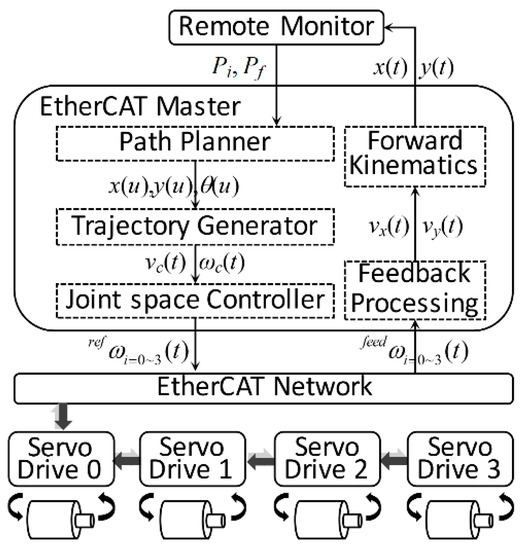
Figure 1.
Network-oriented control architecture for an omnidirectional mobile robot.
The main controller serves as the EtherCAT master handling the path planner, trajectory generator, and the joint space controller. As shown in the figure, the initial and target positions respectively, denoted as Pi and Pf, respectively, are received by the EtherCAT master from the remote monitor. The path planner generates a path between these points without considering temporal parameters. The corresponding linear and angular velocity commands (denoted as vc and ωc, respectively) are produced by the trajectory generator and are decomposed to the joint space velocities through the joint space controller. The joint space velocities are sent to the servo drives on the EtherCAT network to drive the motors. The actual movement are measured by the encoders connected to each motor and the measurements are sent back to the EtherCAT master, which are processed to deduce the current location of the mobile robot in Cartesian space denoted as x(t) and y(t).
In our developed system, four EtherCAT servo drives are employed, each attached with AC motors. In addition, the servo drive supports processing of 19-bit serial encoder and provides three different control modes: velocity, position, and torque control. Thus, we selected motors that are each equipped with an internal 19-bit absolute encoder, used for measuring the actual movement of the motors and calculating the actual position of the robot. To address the size and power requirements, we characterize the main controller to run on the embedded platform i.MX6Q SABRELite, a low-power and low-cost open embedded hardware manufactured by NXP (formerly Freescale) [22]. i.MX6 processors are widely used in different industrial and control applications as it has a quad-core 1.2 GHz ARM Cortex A9 CPU, making it competitive with industrial computers. Although there are various evaluation boards for the i.MX6 processor, we have selected SABRELite because it has the interfaces required to drive a mobile robot while being minimally sized. The embedded platform is equipped with a gigabit Ethernet controller which serves as the interface to connect with the EtherCAT devices. Other hardware interfaces such as SPI, I2C, and UART are also available that can be used to attach different sensors and extend the functionality of the mobile robot.
2.2. Software Architecture
The open-source EtherCAT master—IgH EtherLAB—is required to be implemented under the Linux kernel. The compatible version of embedded Linux kernel that can be implemented on the embedded platform is kernel version 3.14.15 provided in the ARMv7 Multiplatform repository [32]. Although Linux provides libraries and other tools for application development, IgH EtherLAB requires an RTOS to meet real-time guarantees in connection with the EtherCAT slaves. To this end, we have selected Xenomai, a cokernel approach of real-time Linux. Xenomai provides hard real-time support in the user space applications with task synchronization and scheduling mechanisms such as mutex, semaphores, event flags, etc. Xenomai runs alongside the standard Linux kernel through the adaptive domain environment for operating systems or ADEOS, a nanokernel hardware abstraction layer that enables multiple entities called domains to exist in the same hardware. In this configuration, Xenomai has the higher priority and is handled first, causing nonreal-time processes on the standard Linux kernel to have the lowest priority by default. Thus, any standard Linux task will execute, if and only if there are no pending Xenomai tasks.
The Linux kernel is patched with the compatible ADEOS ipipe-3.14.17-arm-2, which is available at the Xenomai i-pipe patch archives [33]. Additional kernel configurations are required to disable CPU features that are prone to voltage and clock frequency changes. These include CONFIG_CPU_FREQ, CONFIG_CPU_IDLE, and CONFIG_KGDB. Buffer overflow detection and protection is also disabled because it can trigger warnings when installing Xenomai. The kernel is compiled including device tree binaries (DTB). DTB is the newest data structure in Linux that contains the information of the devices attached to the embedded platform. In case of the i.MX6Q SABRELite, DTBs are introduced from Linux kernel version 3.8. Thus, a bootloader that can identify this data structure is required for a successful booting process. We have chosen U-Boot 2014.07, which is the most stable bootloader compatible with the platform. The latest version of Xenomai that is compatible with both the Linux kernel and IgH EtherLAB is Xenomai 2.6.5. It is included with user space libraries and tools for easier application development without having to program in the kernel space. Xenomai is compiled with −arch = armv7-a and −mfpu = vfp3, which comprise the architecture of the CPU and floating-point unit (FPU) attached to the i.MX6Q SABRELite. Finally, IgH EtherLAB is installed on the system to ensure deterministic communication with the EtherCAT slaves. The latest version of the EtherCAT master is v1.5.2 The toolchain used to compile all the software sources is gcc-linaro-arm-linux-gnueabihf-4.8.3 and the root filesystem used is minimal Ubuntu 14.04. The real-time environment for the i.MX6 SABRELite, considering the compatibility of each software, is shown in Figure 2. The real-time performance of the Xenomai-based real-time environment for i.MX6Q SABRELite and its comparison to other widely known open embedded hardware platforms was presented in our previous work in [34].
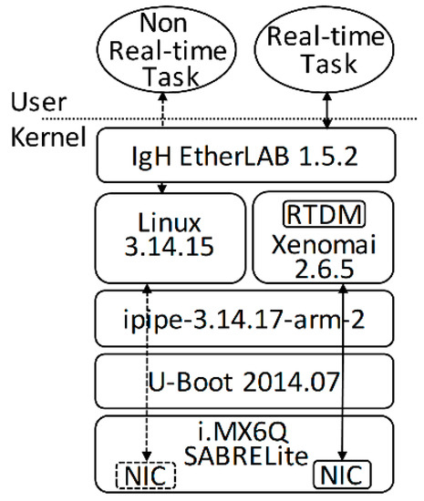
Figure 2.
Real-time environment for the i.MX6Q SABRELite for IgH EtherCAT master.
3. Joint Space Motion of an Omnidirectional Mobile Robot
Advancements in motion control has enabled conventional-wheeled mobile robots to track curved paths with smooth trajectories. However, there are still considerable amounts of lateral and longitudinal slipping (nonholonomic constraints) that constricts movement in all possible directions. To this end, omnidirectional mobile robots are developed employing specially designed wheels. Controlling an omnidirectional mobile robot is a challenging task owing to its kinematics and dynamics in comparison to conventional-wheeled mobile robots. The dynamic model of the mobile robot which is required to implement various control algorithms in real environment having various uncertainties. In this paper, however, we focus on an advanced trajectory generation algorithm based on convolution which was originally characterized for a conventional-wheeled mobile robot with two wheels. The algorithm is modified in accordance to the kinematics model of a four-wheeled omnidirectional mobile robot driven with Mecanum wheels, where we assumed that there is no wheel slippage on the ground and provided references for the derivation of our mathematical model [35]. Trajectory generation for a smooth path is easier to accomplish, but it does not ensure the reliability to track paths with high curvature. Tracking high curvature paths is vital in a practical scenario where an obstacle is present in the working environment. The mobile robot is redirected to a new path to avoid collision with the obstacle that has high curvature turning points. Therefore, we present a trajectory generation technique that improves the original convolution-based algorithm considering the geometrical constraints of a high curvature path. In comparison to our previous work [29], we have provided the description of the algorithm in details. The definition of a high curvature path is included in this paper. The high curvature trajectory is decomposed in the joint space to actuate the EtherCAT-based omnidirectional mobile robot.
3.1. Robot Kinematics and Joint Space Velocities
The kinematics of the omnidirectional mobile robot investigated in this paper is shown in Figure 3. It is driven with four motors and has a rectangular shape. In the figure, the horizontal and vertical distances between the center of the robot and the center of each wheel are denoted as L and l, respectively. The rate of the heading angle at the center of the robot is denoted as ωc. The lateral and longitudinal linear velocities are represented by vx and vy, respectively. These velocities, along with ωc, are decomposed to the joint space velocities denoted as ωi (i = 0,1,2,3) with respect to the radius of the wheels denoted as R.
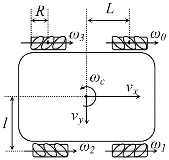
Figure 3.
Simplified kinematics of a four-wheeled omnidirectional mobile robot.
Each of the wheels is driven individually for the robot to perform either lateral or radial movement. The kinematic model highly depends on the wheel configuration and the angle between the rollers and the center of the mobile robot according to the work of Taheri et al. [35]. Assuming that there is no wheel slippage on the ground, the mathematical model of the motion in the joint space in this configuration is expressed in the following equation.
We can easily find a relationship between the central velocity of the mobile robot and the angular velocities at each of its joint. These angular velocities are derived using the following equation.
Thus, the trajectory generator is responsible for producing the linear velocity commands at the center body of the mobile robot (vx and vy) and the angular velocity (ωc). Whereas, the joint space controller converts the central velocity commands into the angular velocities at each of the joints for the actual motion. The following sections discusses a trajectory generator based on convolution, which satisfies the physical limits of the robot and could track a high-curvature path.
3.2. Convolution-Based Path Planning
Yang et al. [28] proposed a path planner based on convolution which produces the center velocity for a two-wheeled mobile robot to track a smooth curve. The convolution operator satisfies physical limitations of the robot, including maximum velocity, maximum acceleration, and maximum jerk. To generate the velocity profile, a square wave function, y0(t), is defined with an area equal to the linear distance of the planned path, S, as shown in the following equation.
By applying the preceding output of the system as the input of the next iteration, successive operation of the digital convolution in uniform sampling time generates the center velocity profile using the following simplified equation.
where, k and mn satisfies k = t/Ts and mn = tn/Ts. tn is the calculated time parameter with respect to the given physical limits. Theoretically, the convolution operator can be applied to infinity; however, the smooth movement of the mobile robot only requires consideration of the jerk limit. Thus, the convolution operator is performed only for two times. However, the convolution operator only considers the linear distance between two points, which is unequal to the actual travel distance along a curved path. We assume that a curve is denoted as ΔS(u), which is uniformly sampled with a defining parameter in the range of 0 ≤ u ≤ 1. The total travel distance along the entire path, Bd, is calculated as
The smoothness of the curve is defined as proportional to the number of samples of the defining parameter. Meaning, a smoother curve is generated with a larger number of u samples. The actual travel distance in (5) is substituted as the input function for the convolution operator. Hence, the center velocity, vc(t), is generated in the time domain. Here, physical limitations, such as maximum velocity, maximum acceleration, maximum jerk, and sampling time are configured to match the specifications of the mobile robot. However, the generated velocity does not consider the heading angles along the curve. Therefore, the defining parameter of the curve is calculated in the time domain using the following equation.
The accumulated distance at each sampling point in the time domain ΔS(u(t)) is obtained by substituting the calculated u(t) parameter in the curve equation to produce a trajectory that considers the heading angles of the curved path. This notation denotes that shorter sampling time can generate more accurate trajectory. Assuming that a path is defined by the time-bounded parameter in (6), then each point along the curve is defined as a function of that parameter or expressed as the coordinates (x(u(t)), y(u(t))). By definition, vx and vy are the rates of change of the position on the x and y axes, respectively. Thus, they are calculated as the derivative of the curved path, or
The heading angle from the center of the mobile robot, θc, at each point along the curve is calculated as
Therefore, the angular velocity at the center body of the mobile robot is equal to the derivative of the heading angle, or
3.3. Trajectory Generator for a High Curvature Path
In the previous section, we discussed a convolution-based path planner which considers the physical limits and the heading angles at the center body of the mobile robot. However, it is inevitable for robots to work in an environment where obstacles exist inside a working environment. The common way to avoid obstacles is to alter the original planned path. For example, generating two additional paths, one for avoiding the obstacle, and the other to connect the deviation and the original target position. However, the deviation usually results to a path with high curvature. In our previous work [29], the geometric constraints present at the turning points of was considered. The convolution-based trajectory generator in the previous section was improved to generate feasible trajectories. This method satisfies both the physical limits of the mobile robot and the geometrical limits due to the high curvature of the curved path. However, it was developed to drive a two-wheeled differential drive mobile robot and did not completely describe the definition of a high curvature. In this paper, we focus on the adaptation of the algorithm for a four-wheeled omnidirectional mobile robot. Assuming a curved path generated in the x- and y-axes with the parameter u(t) in (6), its curvature is defined as
where κ is the curvature of the curve and ρ denotes the radius of curvature. In this notation, we can see that the curvature at each point of the curve is the reciprocal of the radius of a circle that complies at that certain point.
The curvature of the path is analyzed using the first-order derivative (FOD) test or dκ(u(t))/du(t), in order to detect local extrema. A curve is defined to have high curvature when local extrema exist at certain points along the curve. The extrema can either be the maximum or the minimum value of an open interval function, such as the curvature of the path. These are found when the FOD at a certain point of the curve is equal to zero. In Figure 4, two S-curves were generated, and their curvatures analyzed using (10) and the FOD test. Figure 4a shows a smooth curve as there are no existing zero values of the FOD at any sampling points. On the other hand, Figure 4b contains two points where the FOD are zero located at u(t) = 0.055 and at u(t) = 0.944. These points are defined as the turning points of the curve. Thus, any curve that has existing turning points can be defined as a high curvature curve. These turning points contemplate geometric constraints limiting the allowable velocity at that point, as defined in the following equation.
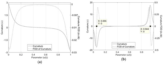
Figure 4.
Definition of a high curvature based on the first-order derivative (FOD): (a) smooth curve and (b) curve with two high curvature turning points.
The velocity at a turning point is determined through the relationship of the radius of curvature and the radial acceleration limit of the robot, armax. In order to consider these constraints, velocity profiles from the initial, terminal, and turning points are generated, with the lowest value at each sampling point is considered to be the maximum allowable velocity that can track the high curvature path. Figure 5 shows a graphical interpretation of the high curvature trajectory generation technique. First, a velocity profile from the initial point to the terminal point is generated in the forward direction applying the convolution operator in (4), as shown in Figure 5a. In perspective, the velocity in the opposite direction from the terminal point would produce the same result as the velocity from the initial point, thus it is neglected.
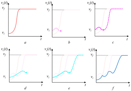
Figure 5.
Graphical interpretation of the high curvature convolution-based trajectory generation.
In the case of the turning points, the maximum velocity at each turning point is calculated using (11). The velocity profile is divided into two parts and is generated with the same distance as that of the first step. For the first portion, the convolution operator is applied in the opposite direction towards the velocity in the initial point as illustrated in Figure 5b. On the second portion, the velocity profile is generated in the opposite direction approaching the terminal point shown in Figure 5c. This step is repeated for the other terminal point, as shown in Figure 5d,e. Finally, the lowest velocity at each point from the various velocity profiles determines the proposed maximum allowable central velocity (MACV), see Figure 5f. This produces a velocity profile that can track a high curvature path while considering the physical limits of the mobile robot owing to the convolution operator. Because the velocity limits at the turning points are taken into consideration, the total traveling time is extended and should be reformulated to conform the travel distance with MACV:
Because of the adjustment in the velocity profile can produce a travel distance which is greater than the calculated Bd and can produce nonuniform displacement and sampling time at each sampling point, the MACV is reformulated using a variation of linear interpolation:
where vuni is the reformulated maximum allowable central velocity. The total travel time, denoted by tn, is calculated by integrating (12). The uniform sampling time t is defined as tn − 1 ≤ t ≤ tn.
This notation makes the convolution-based velocity comply with the path generated with the high curvature in the periodic sampling time. The sequence of major computations for generating the proposed convolution-based joint space trajectory to track a path with high curvature turning points for an omnidirectional mobile robot is as follows.
- Define a planned path through the given terminal and control points in uniform sampling points.
- Calculate the total travel time for a travel distance Bd, according to the given physical limitations of the mobile robot using (5) with the given maximum velocity, acceleration, and jerk values.
- With the calculated travel distance and total travel time as inputs, perform the recursive form of the convolution operator in (4) for two successions to consider the physical limits of the mobile robot such as maximum velocity, acceleration, and jerk.
- From the curve parameter u-domain, transform the path in the time domain using (6).
- For a path with high curvature, calculate the position of the high curvature turning points using (10) and the velocity limits at the turning points using (11).
- Velocity from the high curvature turning points is generated from the turning point to the terminal point in the forward direction and to the initial point in the backward direction, respectively. The maximum allowable velocity at the center of the mobile robot is defined as the minimum values at each sampling point of the combined velocity profiles.
- Because the velocity limits at the turning points are considered, the total traveling time is reformulated to conform the travel distance with MACV using (12). The reformulated MACV is calculated using (13), which is the velocity profile that can track a high curvature path while considering the physical limits of the mobile robot.
- MACV is decomposed to the joint space according to the kinematics of the omnidirectional mobile robot in (2). The linear and angular velocities are calculated in a series of computation using Equations (7)–(10).
4. Synchronous Joint Space Controller
Although the real-time requirements are satisfied, the main controller and all other components of the motion control system should be synchronized in order to accurately track a predefined path especially for the path with high curvature as mentioned above. EtherCAT offers a synchronization solution called the distributed clock, widely known as the DC mechanism. The main idea of the DC mechanism is to adjust the local clocks of each slave in accordance to the reference clock (clock of the first slave on the network). There are two main causes of clock deviations among the slaves in EtherCAT networks: the mismatch of start-up times among the slaves and frequency differences in the oscillators on the slaves. To synchronize clocks between the reference slave and other slaves, EtherCAT uses the DC synchronization mechanism. EtherCAT slaves manage three variables for clock synchronization: system_time, local_time, and reference_time. The system_time is a global clock, beginning from 1 January 2000 and runs at a rate of 1 ns stored in an internal 64-bit register.
The local_time is an internal clock for each slave and represents the time that starts from zero when each slave powers up. The DC-capable slave that is closest to the master is usually chosen as the reference slave, and reference_time is defined as the system_time of the reference slave. The DC synchronization procedure consists of three phases: offset compensation, propagation delay measurement, and drift compensation. The offset of each slave is defined as the time difference between reference_time and local_time of each slave. To determine the offset of each nonreference slave, the master reads the local_time of each slave and calculates its difference with the reference_time. The difference is written into the System_Time_Offset register of each slave [30]. This procedure is performed only once when the system is started. The definition of the system_time is shown in the following equation.
The propagation delay of the EtherCAT slaves (excluding the reference slave) is defined as the time taken to transmit a specific message from the reference slave to the other slaves. Drift compensation occurs every cycle using special EtherCAT commands known as multiple read and write (ARMW or FRMW). These commands are distributed by the master and measures the times when the packet first arrived at each slave and is returned to the same slave around the network. The drift is defined as the time difference between the reference_time and system_time of each slave considering the propagation delay and is defined as follows
The delay occurs due to the frequency difference of the oscillators of each slave. If the calculated average drift is approximately equal to zero, the local clocks of each slave are increased by 10 ns; whereas, 11 ns or 9 ns are added when the slave is detected to be running slower or faster than the reference clock, respectively. According to the results of Cena et al. [30], the DC mechanism can effectively solve the synchronization problem between the EtherCAT slaves on the network. However, synchronization between the EtherCAT master and the slaves was not considered. The asynchronization between the master and the slave can lead to data mismatch. Slower movement of the master clock results in the EtherCAT slaves receiving empty packets for a certain period. On the other hand, when the master is faster, data which are not yet read by the slaves is overwritten by newer data. This problem is critical in robot navigation, where the joint space velocities should be strictly followed to accurately track a planned path. In addition, when a data loss occurs while the mobile robot is accelerating or decelerating, physical constraints such as the maximum acceleration and jerk are violated. This could result into physical damage of the actuators or worse, an accident because of the unpredictable movement of the robot. Due to this synchronization delay, the joint space velocities in (1) are modified to considering the clock drift as shown in (16). This equation contemplates that smaller Δt results to minimal tracking error of a given trajectory.
Various researchers have tried to solve this problem using different control schemes [36,37,38]. However, these algorithms need to run in a separate real-time task, which could reduce the clock accuracy of the EtherCAT master because of context switching jitters. IgH EtherLAB offers APIs to utilize the DC mechanism, which can easily be used inside the real-time control task. However, it relies on the clock services of the RTOS, which can also administer unwanted task jitters. A fast clock synchronization method adjusting the clock of the master in accordance to the reference slave clock is presented by Chen et al. [31]. The method is applied on a Windows PC with RTX real-time extension and commercial EtherCAT master which are not available as an open-source. In this paper, we present a solution that synchronizes the master clock to track the system clock of the reference slave. The clock data from the reference clock is collected periodically to calculate the system. The master clock adjusts its clock speed by changing its cycle time according to the calculated specific value. In comparison to the original DC procedure, jitter of the master would not have any effects on the synchronization delay of the entire EtherCAT network. The distributed clock mechanism offered by IgH EtherLAB is implemented to perform offset compensation and propagation delay measurement. This includes reading of the local_time from all the slaves and calculation of the time_offset, which are sent to back the slaves for correction of the system_time. When the control task enters the real-time cyclic task, the system_time of the reference slave is acquired using the function ecrt_reference_slave_clock(). The calculated drift of the entire network in (15) is acquired by reading the System_Time_Offset of the slaves (register 0X092C) using the function ecrt_master_sync_monitor_process(). Before calling this function, a broadcast read all datagram should be sent using ecrt_master_sync_monitor_queue(). The master clock is adjusted according to the normalized system_time of the reference clock and the calculated drift. The new master clock is passed as the argument to the function ecrt_master_aplication_time(). Finally, all the other slaves are synchronized to the new master clock using the function ecrt_master_sync_slave_clocks(). The flowchart of the improved DC clock synchronization method is shown in in Figure 6.
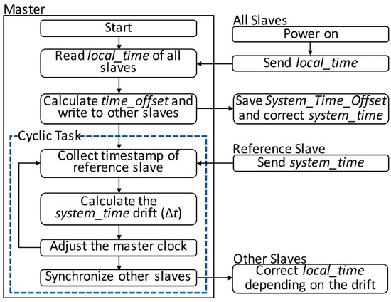
Figure 6.
Flowchart of the improved clock synchronization method.
To validate the improved DC mechanism, comparative analysis is performed running an EtherCAT real-time task in 1 ms cyclic period for 100 s. The results are analyzed and are shown in Figure 7. In Figure 7a, the offset compensation shows that the improved method performs faster offset compensation with the time_offset measured at 5.775 s in comparison to the 8.094 s of the original method. The measured drift is illustrated as the stem graph in Figure 7b. In this figure, an improvement of the drift compensation is clearly visible with the calculated average drift of 24.217 μs. This is a 60% improvement from the original DC mechanism with an average of 39.914 μs. These results gratify that all the components within the EtherCAT network can communicate with minimal synchronization error, which is very critical in synchronous joint space motion of the omnidirectional mobile robot.
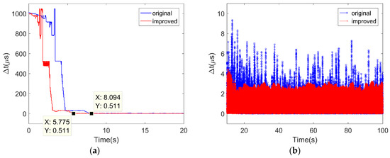
Figure 7.
Comparison between the distributed clock mechanism and its improvement: (a) time_offset and (b) drift compensation.
5. Experimental Results
5.1. Assembly of the Mobile Robot
In the system we developed, we employed four EtherCAT servo drives (L7NA004B) manufactured by LS Mecapion. The devices are operated using CANopen-over-EtherCAT (CoE) with CiA 402 device profile for communication and servo operation. For each slave, the process data objects were configured and divided into 12 bytes each for transmission and receipt, with a total of 24 bytes of data packets in for each EtherCAT cycle. The servo drive supports processing of a 19-bit serial encoder. Thus, we attached a 400-Watt AC servo motor with the rated motor inertia of 0.25 × 10⁴ kg∙m2 at each drive to actuate the wheels of the mobile robot. To avoid incompatibility with the servo drive, we chose a motor from the same manufacturer, APM-FB04AMK, with a rated maximum speed of 5000 revolutions per minute (RPM). Each of the motors is equipped with a built-in 19-bit absolute encoder, which is used for accurate feedback loop control required to ensure that the load reaches the target command. The servo drives also provides three different control modes: velocity, position, and torque control. We have configured them to run in cyclic velocity mode to minimize calculation time and interpolation operations when using other operation modes.
Each of the motors is connected to a reducer gearbox with a reduction ratio of 1:100 for minimal error and higher mobility performance in high speed actuation. In order to achieve omnidirectionality, Mecanum wheels are connected, consisting of 12 rollers with a diameter of 203 mm. The diameter of the rollers is 67 mm. Common Mecanum-wheel mobile robots are either in the form of a parallelogram or a circle. Our developed mobile robot is a parallelogram shaped with the Mecanum wheels attached to constitute a basic 45° driving system. The omnidirectional capabilities of the platform are highly dependent on the contact of each wheel on the surface. Hence, most of the proprietary and commercial designs of a Mecanum-wheel driving system include a suspension. In our design, the wheels and the motors are mounted directly on an aluminum chassis with dimensions of approximately 700 mm and 450 mm in length and width, respectively. Figure 8 shows the mobile robot without the top plate, in order to make the interior as visible as possible.
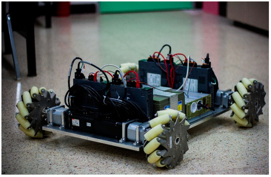
Figure 8.
EtherCAT-based omnidirectional mobile robot.
5.2. Results and Discussion
The main purpose of the experiment is to demonstrate the effects of improving the DC mechanism (Section 4) for the synchronous joint space motion of the four-wheeled omnidirectional mobile robot. The velocity profile is generated in the user space of Xenomai and these commands were sent to the mobile robot using CANopen-over-EtherCAT protocol on a bounded period of 1 ms. For the experiment, we generated and combined three curves, with the second curve having high curvature turning points, to form a path from an initial point of (0 m, 0 m) to a desired terminal point (7 m, 4 m). The initial and terminal velocities and heading angles were configured at 0 m/s and 0°, respectively. The physical limits of the mobile robot required to generate the respective velocity commands are based on the actual constraints of the actuators. According to the motor specifications, the limits are stated as 0.23 m/s for the maximum velocity limit, 0.2 m/s2 for the maximum tangential acceleration, and 0.4 m/s3 for the maximum jerk. The maximum allowable central velocity (MACV) is produced using the convolution operator as mentioned in the second section. Actual joint space velocity commands for the omnidirectional mobile robot were calculated with respect to the robot kinematics in Equations (1) and (2). The diameter of the wheels is 203 mm, and the distance from the center frame to the center of the wheels in both longitudinal (L) and transversal direction (l) are 286 and 298.5 mm, respectively.
The calculated distance of the path is 17.48 m which was traveled by the robot in 93.79 s with the maximum allowable velocity. The trajectory tracking experiment was performed two times to compare the original DC mechanism with the improved method shown in the previous section. During the experiment, the mobile robot was kept isolated to avoid any unwanted interruptions that could affect the performance of the main controller. For this reason, the driving experiment was performed on an ideal environment where the wheels of the mobile robot were lifted to impose freewheeling motion avoiding any disturbances that can convey uncertainties such as slip and friction. Also, all the encoder measurements were stored in a separate buffer for offline processing and analysis. Comparison of the reference and the actual measured joint space velocities are shown in Figure 9. The reference velocities were generated without violating the maximum velocity of the motors (calculated as 0.531 m/s). Although not reported in this paper, previous experiments show undesired hunting oscillations when the motors are operated in a very low speed. Thus, we applied a reducer gearbox with a high reduction ratio of 1:100. The actual values from the encoder show high accuracy in tracking the reference but, with oscillating results, we have used an absolute encoder. The results from the original DC mechanisms are illustrated as the blue solid line with an inverted triangle while the improved DC is shown as the red solid line with a dot marker. Although only with a small difference, the results acquired from the improved DC are located closer to the reference than that of the results from implementing the original DC mechanism.
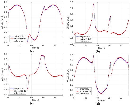
Figure 9.
Comparison between the reference and actual joint space velocities: (a) Wheel 1; (b) Wheel 2; (c) Wheel 3; and (d) Wheel 4.
However, in the Cartesian space, as shown in Figure 10, the difference between the two methods is very conspicuous according to their tracking error with the reference path. In here, the encoder values acquired when actuating the robot using the original DC mechanism is shown in the blue dotted line. On the other hand, the results from the improved DC method are illustrated by the red dash-dot line. The results from the original DC mechanisms show higher tracking error especially in the part with high curvature turning points. Due to the deviation, the robot arrived at the terminal point of 6.802 m, 3.841 m—an error of approximately 4%. In comparison, the improved DC curve was able to track and is closer to the reference path (black line) arriving at the terminal point of 6.951 m, 3.921 m, which is an error of less than 1.3%. Although the tracking error is reduced with the improved DC method, small deviations are still visible in some parts of the curve. These are due to the absolute encoder being unable to follow the motor being driven at a very high speed. Moreover, the reduction gear could also affect the accuracy of the encoder as the physical connection between each gear which can produce the deviations. In actual practice, the dynamics [39,40,41] of the mobile robot should be considered to implement control algorithms to compensate the source of disturbances such as the surface condition of the floor, the change in the mass of the payload, and the internal parameters of the reduction gear.
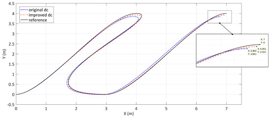
Figure 10.
Comparison of the reference and actual trajectory in tracking a high curvature path driven with the maximum allowable velocity.
6. Conclusions
In this paper, we present a network-oriented, low-cost, real-time embedded system employing EtherCAT protocol to control an omnidirectional mobile considering synchronous joint space motion. The paper provides a real-time environment considering the compatibility of each open-source software available for the embedded platform i.MX6Q SABRELite. For the trajectory generation of the omnidirectional mobile robot, we have adapted our previous work that can track a high curvature path according to the kinematics of a four-wheeled omnidirectional mobile robot and clearly define the geometric constraints. Although the EtherCAT master shows viable real-time performance, the actual motion of the robot requires the trajectory to be decomposed in the joint space, where synchronization is a critical issue. We presented an improvement of the EtherCAT DC mechanism; dynamically adjusting the clock of the EtherCAT master according to the reference slave. This method shows improvement in minimizing the synchronization error between all the components of the network, and faster offset compensation. Experiments were performed on our own developed EtherCAT-based Mecanum-wheeled mobile robot to verify the effects of the improvement of the DC mechanism in tracking a high curvature planned path. In comparison to the original DC mechanism, experimental results acquired from the improved DC method shows higher accuracy in tracking a planned path with high curvature turning points with less than 1.3% of tracking error. However, further studies should be conducted for the practical application of the mobile robot considering its dynamics and implementing control algorithms to compensate external factors, such as the surface condition of the floor, encoders being unable to follow high speed actuation of the motors, and the change in the mass of the load. Although the synchronization method in this paper was applied to the joint space motion of an omnidirectional mobile robot, the same method can be applied in more complex control systems such as industrial automation control networks for smart factories [42], intelligent automotive [43], unmanned vehicles [44], and humanoid robots [13,45].
Author Contributions
R.D. surveyed the background of this research, developed the environment for the embedded hardware, formulated the experiment procedures, and analyzed the results of the experiments. B.W.C. supervised and supported this study.
Acknowledgments
This work was supported by the Human Resources Development of the Korea Institute of Energy Technology Evaluation and Planning (KETEP) grant funded by the Korean government Ministry of Trade, Industry & Energy (NO. 20174030201840).
Conflicts of Interest
The authors declare no conflicts of interest.
References
- Bradley, J.M.; Atkins, E.M. Optimization and control of cyber-physical vehicle systems. Sensors 2015, 15, 23020–23049. [Google Scholar] [CrossRef]
- Guo, Y.; Hu, X.; Hu, B.; Cheng, J.; Zhou, M.; Kwok, R.Y.K. Mobile cyber physical systems: Current challenges and future networking applications. IEEE Access 2018, 6, 12360–12368. [Google Scholar] [CrossRef]
- Kim, H.; Kang, J.; Park, J.H. A light-weight secure information transmission and device control scheme in integration of cps and cloud computing. Microprocess. Microsyst. 2017, 52, 416–426. [Google Scholar] [CrossRef]
- You, B.-J.; Kwon, J.R.; Nam, S.-H.; Lee, J.-J.; Lee, K.-K.; Yeom, K. Coexistent space: Toward seamless integration of real, virtual, and remote worlds for 4d+ interpersonal interaction and collaboration. In Proceedings of the SIGGRAPH Asia 2014 Autonomous Virtual Humans and Social Robot for Telepresence, Shenzhen, China, 3–6 December 2014; pp. 1–5. [Google Scholar]
- Terakawa, T.; Komori, M.; Matsuda, K.; Mikami, S. A novel omnidirectional mobile robot with wheels connected by passive sliding joints. IEEE/ASME Trans. Mechatron. 2018, 23, 1716–1727. [Google Scholar] [CrossRef]
- Kato, K.; Wada, M. Kinematic analysis and simulation of active-caster robotic drive with ball transmission (acrobat-s). Adv. Robot. 2017, 31, 355–367. [Google Scholar] [CrossRef]
- Wang, C.; Liu, X.; Yang, X.; Hu, F.; Jiang, A.; Yang, C. Trajectory tracking of an omni-directional wheeled mobile robot using a model predictive control strategy. Appl. Sci. 2018, 8, 231. [Google Scholar] [CrossRef]
- Yamada, N.; Komura, H.; Endo, G.; Nabae, H.; Suzumor, K. Spiral mecanum wheel achieving omnidirectional locomotion in step-climbing. In Proceedings of the 2017 IEEE International Conference on Advanced Intelligent Mechatronics (AIM), Munich, Germany, 3–7 July 2017; pp. 1285–1290. [Google Scholar]
- Cherubini, A.; Passama, R.; Crosnier, A.; Lasnier, A.; Fraisse, P. Collaborative manufacturing with physical human–robot interaction. Robot. Comput. Integr. Manuf. 2016, 40, 1–13. [Google Scholar] [CrossRef]
- Larrea, M.; Larzabal, E.; Irigoyen, E.; Valera, J.J.; Dendaluce, M. Implementation and testing of a soft computing based model predictive control on an industrial controller. J. Appl. Logic 2015, 13, 114–125. [Google Scholar] [CrossRef]
- Choi, T.; Kyung, J.; Park, C.; Park, D.; Do, H. Real-time synchronisation method in multi-robot system. Electron. Lett. 2014, 50, 1824–1826. [Google Scholar] [CrossRef]
- Gago, J.J.; Victores, G.J.; Balaguer, C. Sign language representation by teo humanoid robot: End-user interest, comprehension and satisfaction. Electronics 2019, 8, 57. [Google Scholar] [CrossRef]
- Jung, T.; Lim, J.; Bae, H.; Lee, K.K.; Joe, H.-M.; Oh, J.-H. Development of the humanoid disaster response platform drc-hubo+. IEEE Trans. Robot. 2018, 34, 1–17. [Google Scholar] [CrossRef]
- Al Mamun, M.A.; Nasir, M.T.; Khayyat, A. Embedded system for motion control of an omnidirectional mobile robot. IEEE Access 2018, 6, 6722–6739. [Google Scholar] [CrossRef]
- Arvin, F.; Espinosa, J.; Bird, B.; West, A.; Watson, S.; Lennox, B. Mona: An affordable open-source mobile robot for education and research. J. Intell. Robot. Syst. 2018. [Google Scholar] [CrossRef]
- López-Rodríguez, F.M.; Cuesta, F. Andruino-a1: Low-cost educational mobile robot based on android and arduino. J. Intell. Robot. Syst. 2015, 81, 63–76. [Google Scholar] [CrossRef]
- ETG. Ethercat. Available online: https://www.ethercat.org/default.htm (accessed on 22 November 2018).
- Delgado, R.; Kim, S.; You, B.; Choi, B. An ethercat-based real-time motion control system in mobile robot application. In Proceedings of the 2016 13th International Conference on Ubiquitous Robots and Ambient Intelligence (URAI), Xi’an, China, 19–22 August 2016; pp. 710–715. [Google Scholar]
- Ferdoush, S.; Li, X. Wireless sensor network system design using raspberry pi and arduino for environmental monitoring applications. Procedia Comput. Sci. 2014, 34, 103–110. [Google Scholar] [CrossRef]
- Honegger, D.; Meier, L.; Tanskanen, P.; Pollefeys, M. An open source and open hardware embedded metric optical flow cmos camera for indoor and outdoor applications. In Proceedings of the 2013 IEEE International Conference on Robotics and Automation (ICRA), Karlsruhe, Germany, 6–10 May 2013. [Google Scholar]
- Kaliński, K.J.; Mazur, M. Optimal control at energy performance index of the mobile robots following dynamically created trajectories. Mechatronics 2016, 37, 79–88. [Google Scholar] [CrossRef]
- NXP. I.Mx6q Sabrelite. Available online: https://www.nxp.com/products/processors-and-microcontrollers/applications-processors/i.mx-applications-processors/i.mx-6-processors/sabre-board-for-smart-devices-based-on-the-i.mx-6quad-applications-processors:RD-IMX6Q-SABRE (accessed on 27 December 2018).
- Delgado, R.; You, B.-J.; Choi, B.W. Real-time control architecture based on xenomai using ros packages for a service robot. J. Syst. Softw. 2019, 151, 8–19. [Google Scholar] [CrossRef]
- Li, J.; Pilkington, N.T.; Xie, F.; Liu, Q. Embedded architecture description language. J. Syst. Softw. 2010, 83, 235–252. [Google Scholar] [CrossRef]
- Pose, F. Igh Ethercat Master 1.5.2 Documentation. Available online: https://www.etherlab.org/download/ethercat/ethercat-1.5.2.pdf (accessed on 12 November 2018).
- Abbott, D. Linux for Embedded and Real-Time Applications, 4th ed.; Butterworth-Heinemann: Newton, MA, USA, 2003. [Google Scholar]
- Choi, B.W.; Shin, D.G.; Park, J.H.; Yi, S.Y.; Gerald, S. Real-time control architecture using xenomai for intelligent service robots in usn environments. Intell. Serv. Robot. 2009, 2, 139–151. [Google Scholar] [CrossRef]
- Yang, G.J.; Delgado, R.; Choi, B.W. A practical joint-space trajectory generation method based on convolution in real-time control. Int. J. Adv. Robot. Syst. 2016, 13, 56. [Google Scholar] [CrossRef]
- Delgado, R.; Choi, B.W. Practical high curvature path planning algorithm in joint space. Electron. Lett. 2015, 51, 469–471. [Google Scholar] [CrossRef]
- Cena, G.; Bertolotti, I.C.; Scanzio, S.; Valenzano, A.; Zunino, C. Evaluation of ethercat distributed clock performance. IEEE Trans. Ind. Inform. 2012, 8, 20–29. [Google Scholar] [CrossRef]
- Chen, X.; Li, D.; Wan, J.; Zhou, N. A clock synchronization method for ethercat master. Microprocess. Microsyst. 2016, 46, 211–218. [Google Scholar] [CrossRef]
- Nelson, R.C. Armv7-Multiplatform. Available online: https://github.com/RobertCNelson/armv7-multiplatform (accessed on 17 January 2019).
- Xenomai Adeos Archive. Available online: https://xenomai.org/downloads/ipipe/v3.x/arm/older/ (accessed on 17 January 2019).
- Delgado, R.; Park, J.; Choi, W.B. Open embedded real-time controllers for industrial distributed control systems. Electronics 2019, 8, 223. [Google Scholar] [CrossRef]
- Taheri, H.; Qiao, B.; Ghaeminezhad, N. Kinematic model of a four mecanum wheeled mobile robot. Int. J. Comput. Appl. 2015, 113, 6–9. [Google Scholar] [CrossRef]
- Ferrari, P.; Flammini, A.; Marioli, D.; Taroni, A. A distributed instrument for performance analysis of real-time ethernet networks. IEEE Trans. Ind. Inform. 2008, 4, 16–25. [Google Scholar] [CrossRef]
- Ganz, D.; Leschke, S.; Doran, H.D. Imporoving ethercat master-slave syncrhonization precision using ptcp embedded in ethercat frames. In Proceedings of the 2015 IEEE World Conference on Factory Communication Systems, Palma de Mallorca, Spain, 27–29 May 2015. [Google Scholar]
- Park, S.-M.; Kim, H.; Kim, H.-W.; Cho, C.N.; Choi, J.-Y. Synchronization improvement of distributed clocks in ethercat networks. IEEE Commun. Lett. 2017, 21, 1277–1280. [Google Scholar] [CrossRef]
- Zimmermann, K.; Zeidis, I.; Abdelrahman, M. Dynamics of mechanical systems with mecanum wheels. In Applied Non-Linear Dynamical Systems; Awrejcewicz, J., Ed.; Springer International Publishing: Cham, Switzerland, 2014; pp. 269–279. [Google Scholar]
- Weiss, A.; Langlois, R.G.; Hayes, M.J.D. Dynamics and vibration analysis of the interface between a non-rigid sphere and omnidirectional wheel actuators. Robotica 2015, 33, 1850–1868. [Google Scholar] [CrossRef]
- Oliveira, H.P.; Sousa, A.J.; Moreira, A.P.; Costa, P.J. Dynamical models for omni-directional robots with 3 and 4 wheels. In Proceedings of the ICINCO 2008 5th International Conference on Informatics in Control, Automation and Robotics, Madeira, Portugal, 11–15 May 2008; pp. 189–196. [Google Scholar]
- Chen, B.; Wan, J.; Shu, L.; Li, P.; Mukherjee, M.; Yin, B. Smart factory of industry 4.0: Key technologies, application case, and challenges. IEEE Access 2018, 6, 6505–6519. [Google Scholar] [CrossRef]
- Cummings, R.; Richter, K.; Ernst, R.; Diemer, J.; Ghosal, A. Exploring use of ethernet for in-vehicle control applications: Afdx, ttethernet, ethercat, and avb. SAE Int. J. Passeng. Cars Electron. Electr. Syst. 2012, 5, 72–88. [Google Scholar] [CrossRef]
- Ju, C.; Son, I.H. Multiple uav systems for agricultural applications: Control, implementation, and evaluation. Electronics 2018, 7, 162. [Google Scholar] [CrossRef]
- Muratore, L.; Laurenzi, A.; Hoffman, E.M.; Rocchi, A.; Caldwell, D.G.; Tsagarakis, N.G. Xbotcore: A real-time cross-robot software platform. In Proceedings of the 2017 First IEEE International Conference on Robotic Computing (IRC), Taichung, Taiwan, 10–12 April 2017; pp. 77–80. [Google Scholar]
© 2019 by the authors. Licensee MDPI, Basel, Switzerland. This article is an open access article distributed under the terms and conditions of the Creative Commons Attribution (CC BY) license (http://creativecommons.org/licenses/by/4.0/).