Abstract
Applied tests on a real photovoltaic panel for a consolidated analysis require complex experiment setup and permanent availability of climatic conditions. This method is ineffective and can damage the PV system. As a result, PV emulators are highly requested in solar energy conversion and generation research, which rests essentially on a maximum power point tracking control algorithm (MPPT) and an adapting power stage as the DC-DC converter and PV inverter. The PV emulator guarantees a controllable light source environment to act as a real PV system in the laboratory. This paper deals with the study and development of an experimental PV emulator based on logarithmic approximation of the ideal single diode model (ISDM), which is implemented using analog electronic components. Mainly, the PV model, the controller, and the power stages, forming the PV emulator, are described. This simple, low-cost, and efficient device is considered as a nonlinear power supply template replacing the real PV system for any operating point irrespective of the environmental condition changes. The emulated current-voltage and power-voltage curves are validated via resistive load and batteries. Then, the performance of the proposed PV emulator is evaluated by its ability to recharge properly two 12V 7 Ah batteries.
1. Introduction
To reproduce I = f(V) and P = f(V) characteristics of a PV system in the laboratory for a reliable, rapid, and efficient PV energy conversion systems analysis and improvement, two methods are applied. The conventional one consists of developing an experimental platform using the light emitting diode or the halogen lamp as the controllable artificial light for the PV module [1]. Consequently, a large amount of power and a wide space area are needed to set-up the necessary equipment to control and generate the artificial light. In addition, the test bench configuration is complex and the temperature manipulation is not possible [2]. PV emulators are considered as alternative solutions for the conventional emulation method. A PV emulator system represents a reconfigurable DC power source to reproduce the output electrical characteristics of different PV module regardless of external atmospheric conditions so that the actual PV power system operation can be validated precisely. This tool offers a convenient ambient condition control for steady state and transient responses, which allow simple, rapid, and accurate experiments and tests for the PV energy conversion system. There are commercial PV emulators available in the market offering a variable power range from a PV module to a PV array emulations such as Elgar ETS60X14C-PVF and Magna Power TSD50050240 [3,4]. Nevertheless, the major disadvantage preventing their frequent use by researchers is a high cost.
Researchers treated and discussed several methodologies of PV emulators over the years. PV cell, module, and array emulators have been studied for about 30 years. The first PV emulator prototype was developed based on the analog circuit [5]. After that, parallel to the development of technologies related to the electric field, researchers have improved the projected studies on PV emulators. Clearly, the PV emulator, as shown in Figure 1, includes three parts called the PV model, the control strategy, and the power stage.
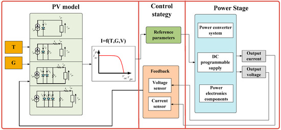
Figure 1.
General PV emulator parts.
In the literature, some PV emulators are classified based on their power range [6,7,8]. Others are categorized by PV model representation [9,10], given that PV cell and its modeling are the most important key parts of any PV emulation structures. Whatever the elaborate model, the goal to be achieved is to have data in all operating conditions, which is derived from the PV emulator that closely mimics the behavior of real solar cells. Through the equivalent circuit, many models of varying complexity degrees have been proposed. The models started with the ISDM as rudimentary one to the Rs-model, then to the Rp-model, the two-diode model, and, finally, the three-diode model. Relatively, the more complicated the model is, the more parameters number is important requiring more computing time and use of complex algorithms by an emulator to generate output results.
Several control strategies, which affect the PV accuracy, transient response, and steady state response and connect the PV model to the power stage, were used to determine and locate the PV emulator operating point as the real PV module I = f(V) curve. In References [11,12,13], authors used the direct referencing method as a common and simple control method that exploit the PI regulator and power converter dynamic characteristics to find the operating point. However, the wrong sizing of external factors and parameters as well as their dependence cause significant oscillations at the emulator output. To overcome this problem, authors in References [14,15] have chosen a fixed step size of the duty cycle for controlling the PV emulator to produce a more stable output. Furthermore, authors in Reference [16] have considered the hybrid-mode controlled method to improve the dynamic performance of the PV emulator affected by the small step size. Despite the oscillations that have been reduced and the performances that have been improved, this method requires a complex control algorithm and is expensive since two different systems are controlled, implemented, and powered. The resistance comparison method determines the output resistance of the PV emulator digitally across its output current and voltage [17]. Other control techniques ensuring a numerical reference current–voltage generation are presented in References [18,19]. Although this procedure offers more stable feedback, a very high computation is required and a digital implementation support with high cost is invoiced. The analog-based method is distinguished with rapidity, simplicity, and low-cost setup. PV emulators analog control are built around variable resistance, power amplifier, the DC power source, and the photo sensor [20,21,22]. A PV emulator via curve fitting employing a current regulator was presented in Reference [23].
The power stage part can be interfaced with switching or linear components. The switching power stage should operate in the buck mode to carefully reproduce the emulated I = f(V) curve [11] such as the use of DC-DC buck converter, half-and-full bridge DC-DC converter, the three-phase AC-DC voltage source, and the current source rectifier and DC programmable power supply [24,25,26]. These emulator topologies are highly demanded in high power applications. Linear PV source emulators are also invoked in the literature [27]. They are excellent in dynamic response, have a wide bandwidth and high resolution, and are effective especially in low power applications. The PV emulator is designed to predict the behavior of a real PV system to test the MPPT control algorithm and estimate the efficiency of the PV energy conversion system and to study and analyze power converters and PV system interactions [28,29,30,31,32,33].
For all PV emulator templates, there is always a compromise between rapidity, efficiency, robustness, and complexity. The main objective is to reproduce closely the behavior of the studied PV system. This paper presents a simple, fast, and accurate PV emulator-based analog electronic component. The proposed PV emulator has a low cost compared with commercial and digital-controlled PV emulators. A logarithmic approximation of the ISDM was considered in this study. The power stage that consists of the DC power supply feeding a controlled linear voltage regulator, which are parallel-connected to variable resistors or batteries, exhibits the PV output characteristics. The performance of the proposed PV test bench is deducted by the comparison between emulated curves and reference ones. This paper is organized as follows: Section 2 presents the electrical circuit and the logarithmic approximation of the ISDM. Section 3 details the methodology as well as the controller design of the proposed PV emulator. In this section, the device is set up using analog electronic components such as the logarithmic amplifier and linear voltage regulators. Experimental tests, operation evaluation, and system performance are discussed in Section 4. We finish this paper by some remarks and conclusions.
2. PV Model and Characteristics
Photon absorption from light, electron charges release and a part of solar energy conversion into electricity are ensured by the key components of the PV systems such as the PV cells. However, the remaining energy of the photon will produce heat lost in the PV module and increase the temperature of the cell. In general, commercial PV modules are housed on metal, and are then covered with anti-reflective coating to minimize the reflection as well as a special laminate for mechanical protection.
For the PV system representation, two types of the PV model are considered either the electrical circuit model, which includes the PV electricity model and the PV thermal model [34,35], or the interpolation model. Figure 2 presents a description of the PV model type in PV emulator applications.
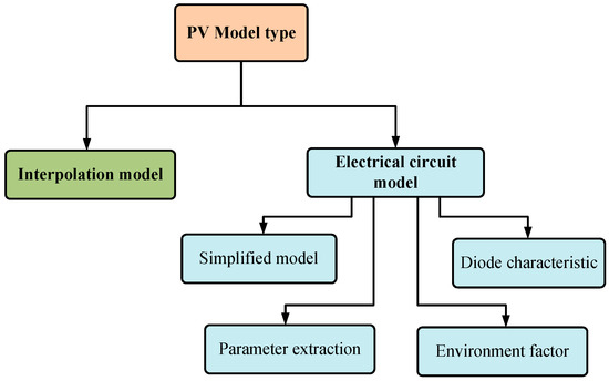
Figure 2.
Description of the PV model type considered in PV emulator applications.
The PV interpolation model is a mathematical function that intercepts the short circuit current and the open circuit voltage for producing the I = f(V) characteristic curve of the PV module. Many researchers have considered this model in the PV emulator establishment [14,36,37].
According to the Kirchhoff law [38], the PV characteristic equation is derived through the analytical method and an electrical circuit represents the PV model. The single diode model is the primitive, common, and popular PV model. In this work, we have used the ideal single diode model to describe and emulate the PV module characteristics.
The photocurrent, Iph, comes from a photovoltaic effect that depends on the semiconductor material absorption capacity as well as the incident irradiation flux [39]. The ISDM model is depicted in Figure 3.
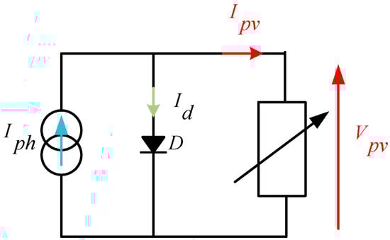
Figure 3.
Electrical circuit of the ISDM.
The output current of the ideal single diode model is given by Equation (1).
where Id is the well-known Shockley diode current, I0 is the saturation current, q is the electron’s charge constant value, a is the diode ideal factor, k is the Boltzmann’s constant, and T represents the junction temperature. Clearly, this model requires three parameters, which are Iph, I0, and a in order to perfectly characterize the I = f(V) output curve [40]. Graphically, as illustrated in Figure 4, Ipv can be determined by the superposition of the curve vertical translation determined by Iph and the exponential shape defined by Id.
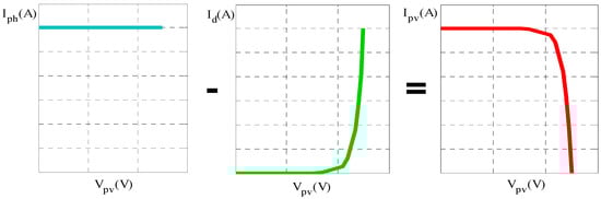
Figure 4.
Photocurrent and diode current superposition.
The nonlinear Equation (1) requires a numerical method to be solved. As an approach proposed by Reference [41], equations as expressed by Equations (2)–(4) could be calculated by analyzing the manufacturer features and the real measured I = f(V) curve of the PV module. As a typical example, the Solarex MSX-60 60W module will be used to illustrate and verify this study.
where G and Gn are, respectively, the incident solar irradiance and the solar irradiance at Standard Conditions Test (STC) (1000 W/m2), Isc and Iscn are the short circuit current, and the short circuit current at STC, respectively, ki is the temperature coefficients of the short circuit current, Vocn is the open circuit voltage at STC, Vg is the energy band, and Tn is the temperature at STC (25 °C). Typical I = f(V) and P = f(V) curves plotted under STC using SIDM are shown in Figure 5.
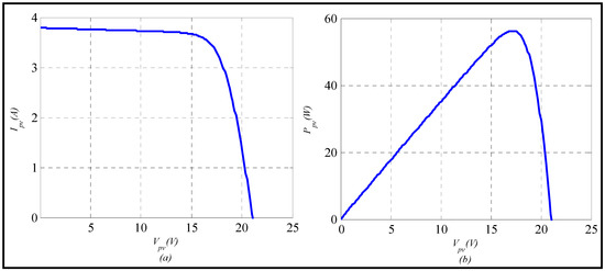
Figure 5.
Typical PV characteristics under STC: (a) I = f(V) and (b) P = f(V).
The PV modules simulation under real climate conditions remains difficult because the software part must be very efficient since the inertia of temperature and irradiation is important and requires more time to be simulated. Therefore, researchers consider the variation of their profiles constant or by the level to characterize the behavior of these systems.
3. PV Emulator Methodology and Controller Design
To emulate the behavior of real PV systems in the laboratory, either the PV current is expressed as a function of T, G, and Vpv as already widespread or we express PV voltage versus T, G, and Ipv. These representations are, respectively, an exponential or logarithmic form. The proposed PV emulator is designed based on analog circuits, which is constructed around operational amplifiers, logarithmic amplifier, variable resistors, adjustable linear voltage regulator, the DC power supply, and power loads to reproduce Vpv = (T,G,Ipv) data. Figure 6 presents the general block structure of this PV emulator.
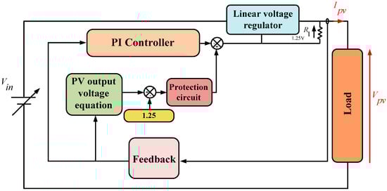
Figure 6.
General structure of the proposed PV emulator.
3.1. Output PV Characteristic Voltage for Linear Voltage Regulator Adjustment
By manipulating the logarithm function, Equation (1) is rewritten as:
where is the thermal voltage and Ns is the number of series PV cells.
Considering , Equation (1) is simplified as follows:
Mathematical development of Equation (6) is given by:
The PV emulator is designed around adjustable linear voltage regulators to provide a malleable output voltage ensuring an accurate imitation of the PV module characteristics. The output voltage is controlled by an external circuit. The controller is implemented to lead a measured current at the system output as close as possible to the reference current. Moreover, in order to compensate the voltage drop across the resistor R1, which is equal to 1.25 V, the output PV voltage is reduced by 1.25 V determining the output PV characteristic voltage as a reference voltage of the emulator as expressed:
3.2. PV Emulator Component Controller Modeling
Essentially, two parts are modeled by analog devices in the proposed PV emulator such as the controller which contains the PV model type, i.e., the output PV characteristic voltage, the PI regulator, and treatment feedback signals stage and the power stage represented by linear voltage regulators, the DC power supply, and power loads. The current sensor allows us to measure the load current. Then, the treatment circuit will process and adapt the corresponding voltage image in order to achieve the considered mathematical equation by carefully using the analog component. The obtained voltage is subtracted, through operational amplifiers and resistors, from the reference photocurrent, Iph*. A logarithmic amplifier consists of operational amplifiers and transistors, as presented in Figure 7. This circuit provides a logarithmic output for a given input and contributes to reproducing the reference voltage Vref.
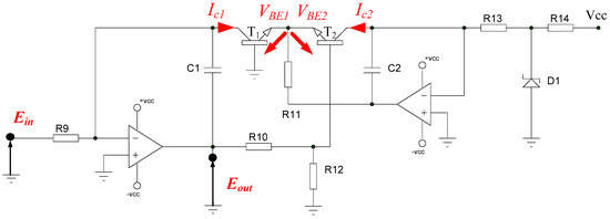
Figure 7.
Electrical circuit of the logarithmic amplifier.
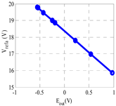
The logarithmic amplifier’s output is a function of:
Logarithmic amplifier principle is based on the inherent logarithmic relationship between collector currents Ic1 and Ic2 and the voltages VBE1 and VBE2 in the two bipolar transistors T1 and T2, given by the following equation.
The output voltage describing the logarithmic circuit operation is written as Equation (11).
Given that , and the input logarithmic amplifier then
Some practical values are given in Table 1.

Table 1.
Practical values components of the logarithmic amplifier circuit.
Some developments allow us to rewrite Equation (8) as follows:
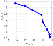
Given that the real PV operating area is located between 60% and 80% of its open circuit voltage Voc and from Isc, the proposed PV emulator should imitate properly the PV characteristics in this interval. In order to achieve a smooth transition between the different components of the emulator, . Clampers are used at the output of the current controller to protect and maintain acceptable voltages at the emulator output. Synoptic diagram of the proposed PV emulator based on Equation (13) is depicted in Figure 8.
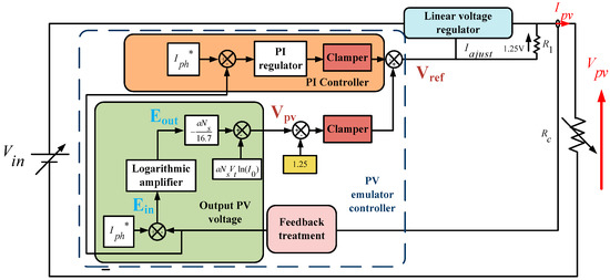
Figure 8.
Detailed synoptic diagram of the proposed PV emulator.
4. Practical Implementation and Experimental Results
In order to verify the operation of the proposed PV emulator, a practical implementation of MSX-60 module features has been carried out. Based on analog electronic components, the PV emulator controller operates as follows: the HX50-P sensor ensures the current acquisition and, subsequently, an amplifier-based circuit will process and condition the recovered image voltage. Iph* is introduced and adjusted via a potentiometer and a voltage divider to calculate the input voltage, Ein, of the logarithmic amplifier circuit. The latter is made around a double amplifier LF412 component, which operates even with a very low input voltage and is insensitive to noise, given that operational amplifiers were designed to perform mathematical operations in analog calculators. The output voltage variation of the logarithmic amplifier, Eout as a function of its input voltage Ein, and some other blocks are validated experimentally, as illustrated in Table 2.
Table 2.
Experimental results of the PV emulator as different block circuits.
By Figure 9, we present the electrical scheme of the PV controller.
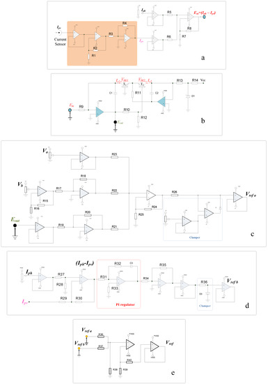
Figure 9.
Electrical schematic analog components of the PV emulator controller legend: (a) Treatment circuit. (b) Logarithmic amplifier circuit. (c) PV characteristic voltage. (d) PI controller circuit. (e) comparator circuit.
The power circuit is based on the LM338 regulators, which are able to support 5 A over an output voltage range of 1.2 V to 32 V. Parallel-placed linear regulators have been completed to enhance the emulator output current, as shown in Figure 10, which allows us to reproduce the PV modules parallel connection topology. For each variation, the flowing current in the load corresponds to the emulated PV current. Experimental results were compared with the Matlab/Simulink module simulation. An initial irradiance level was set to the STC value and we have considered both loads as the variable resistors and batteries.
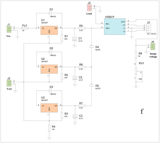
Figure 10.
Parallel-placed LM338 regulators in the PV emulator power stage.
In order to validate the experimental results, we have considered that the PV emulator operates under STC with a constant temperature and an irradiation equal to 25 °C and 1000 W/m2 to obtain the emulated electrical characteristics I = f(V) and P = f(V). A photo of the PV emulator is presented in Figure 11. The simulation parameters of the Solarex polycrystalline silicon PV module are listed in Table 3.
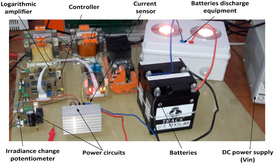
Figure 11.
Photo of the experimental test bench.
Table 3.
Manufacturing PV module parameters of Solarex MSX-60.
The experimental PV characteristics shapes plotted under STC using resistive load are shown in Figure 12.
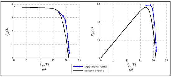
Figure 12.
PV emulated characteristics using the resistor load under STC: (a) I = f(V) curve. (b) P = f(V) curve.
The level of irradiation was set for the photovoltaic emulator via the potentiometer. From the analysis, we have some findings regarding the performance of the proposed emulator. Since the operating point of the PV module is measured between 60% and 80% of Voc, this emulator is able to repeat the simulated PV module dynamic behavior with acceptable accuracy. Afterward, two 12V 7 Ah batteries placed in series and partially discharged have replaced the resistor load. The results are illustrated in Figure 13.
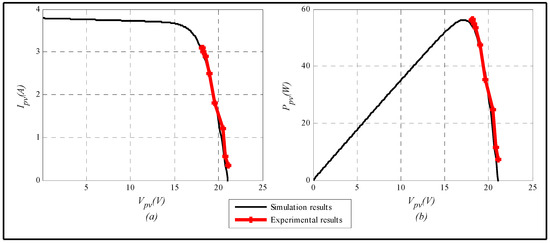
Figure 13.
PV emulated characteristics using batteries under STC: (a) I = f(V) curve. (b) P = f(V) curve.
Note that the obtained I = f(V) and P = f(V) characteristics from the emulator near the operating point of the MSX-60 PV module are very close to simulated ones for this load type. The results agree, which proves the efficiency and accuracy of the designed emulator system by analog electronic components. During the emulation experiment via batteries, as given in Figure 14, current, Ibat and voltage, Vbat were plotted as a function of the recharge time of the batteries while the generated battery voltage is plotted versus the current battery.
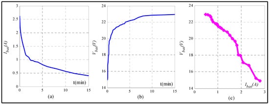
Figure 14.
Batteries recharging profiles versus time: (a) Ibat. (b) Vbat. (c) battery generated voltage.
At the beginning of the recharging process, the current, Ibat, is limited and the voltage, Vbat, increases slightly until reaching regulated voltage. Afterward, the second so-called filling phase is ensured and the battery voltage remains perfectly stable while the battery current decreases. The recharging process is completed when the Ibat falls below the threshold, which is defined according to the battery nature. Batteries behave as a voltage generator, as presented in Figure 14c, which represents the electrical characteristic Vbat = f(Ibat) of the batteries. Consequently, the behavior of the proposed PV emulator based on the analog components is validated and the batteries are successfully recharged through this experimental device.
5. Conclusions
In this paper, a low cost PV emulator based on ideal single diode model linearization was presented. A detailed study was carried out by analyzing mathematical equations and electrical equivalent circuit representation of the constructed PV source. The proposed emulator has been designed to precisely reproduce accurate I = f(V) and P = f(V) characteristics of a typical 60 W PV module in the laboratory at different load and environmental conditions by evaluating the transient and steady state responses. Mainly, two stages are considered in the proposed work. The emulator controller stage consists of a PI regulator and logarithmic approximation of the PV characteristic voltage, which is implemented through analog electronic components, whereas the power stage includes a DC power supply, linear voltage regulators, resistive load, and a series of connected batteries. The emulator was extended to emulate three photovoltaic modules, which are connected in parallel. The comparison between the reference PV characteristics and experimental results shows that the emulated output results are highly similar to the transient response for both resistive load and batteries. The batteries as load type of the PV emulator and the recharging process prove the emulator performance. As a result, the proposed control strategy provides a perfect matching among simulated curves by ensuring simple, fast, and accurate emulation of the PV characteristic near the PV operating points. The emulator developed in this study is a useful device for the researcher and the industrial sector that can support future studies about PV energy conversion system applications. The proposed experimental test bench has the advantage of high bandwidth, which is an essential criteria for testing high frequency MPPT algorithms.
Author Contributions
Conceptualization, I.M. and A.K. Methodology, I.M. and A.B. Software, I.M. Validation, I.M. and A.K. Investigation, I.M. Writing—original draft preparation, I.M. Writing—review and editing, A.K. Visualization, I.M. Supervision, A.K.
Funding
This research received no external funding.
Conflicts of Interest
The authors declare no conflict of interest.
References
- Ayop, R.; Tan, C.W. A novel photovoltaic emulator based on current-resistor model using binary search computation. Sol. Energy 2018, 160, 186–199. [Google Scholar] [CrossRef]
- Ayop, R.; Tan, C.W. A comprehensive review on photovoltaic emulator. Renew. Sustain. Energy Rev. 2017, 80, 430–452. [Google Scholar] [CrossRef]
- Ametek Programmable Power. Available online: http://www.programmablepower.com (accessed on 12 November 2018).
- Magma Power. Available online: http://www.magna-power.com (accessed on 12 November 2018).
- Vachtsevanos, G.; Kalaitzakis, K. A hybrid photovoltaic simulator for utility interactive studies. IEEE Trans. Energy Convers. 1987, 2, 227–231. [Google Scholar] [CrossRef]
- Wandhare, R.G.; Agarwal, V. A low cost, light weight and accurate photovoltaic emulator. In Proceedings of the 37th IEEE Photovoltaic Specialists Conference (PVSC), Seattle, WA, USA, 19–24 June 2011; pp. 1887–1892. [Google Scholar]
- Ram, J.P.; Manghani, H.; Pillai, D.S.; Babu, T.S.; Miyatake, M.; Rajasekar, N. Analysis on solar PV emulators: A review. Renew. Sustain. Energy Rev. 2018, 81, 149–160. [Google Scholar] [CrossRef]
- Balato, M.; Costanzo, L.; Gallo, D.; Landi, C.; Luiso, M.; Vitelli, M. Design and implementation of a dynamic FPAA based photovoltaic emulator. Sol. Energy 2016, 123, 102–115. [Google Scholar] [CrossRef]
- Chin, V.J.; Salam, Z.; Ishaque, K. Cell modelling and model parameters estimation techniques for photovoltaic simulator application: A review. Appl. Energy 2015, 154, 500–519. [Google Scholar] [CrossRef]
- Wang, Y.; Yang, Y.; Fang, G.; Zhang, B.; Wen, H.; Tang, H.; Fu, L.; Chen, X. An Advanced Maximum Power Point Tracking Method for Photovoltaic Systems by Using Variable Universe Fuzzy Logic Control Considering Temperature Variability. Electronics 2018, 712, 355. [Google Scholar] [CrossRef]
- Koran, A.; LaBella, T.; Lai, J.-S. High efficiency photovoltaic source simulator with fast response time for solar power conditioning systems evaluation. IEEE Trans. Power Electron. 2014, 29, 1285–1297. [Google Scholar] [CrossRef]
- Zhang, J.; Wang, S.; Wang, Z.; Tian, L. Design and realization of a digital PV simulator with a push-pull forward circuit. J. Power Electron. 2014, 14, 444–457. [Google Scholar] [CrossRef]
- Roncero-Clemente, C.; Romero-Cadaval, E.; Minambres, V.M.; Guerrero-Martinez, M.A.; Gallardo-Lozano, J. PV array emulator for testing commercial PV inverters. Elektron. Elektrotech. 2013, 19, 71–75. [Google Scholar] [CrossRef]
- Gonzalez-Llorente, J.; Rambal-Vecino, A.; Garcia-Rodriguez, L.A.; Balda, J.C.; Ortiz-Rivera, E.I. Simple and efficient low power photovoltaic emulator for evaluation of power conditioning systems. In Proceedings of the IEEE Applied Power Electronics Conference and Exposition (APEC), Long Beach, CA, USA, 20–24 March 2016; pp. 3712–3716. [Google Scholar]
- Erkaya, Y.; Moses, P.; Flory, I.; Marsillac, S. Development of a solar photovoltaic module emulator. In Proceedings of the 42nd IEEE Photovoltaic Specialist Conference (PVSC), New Orleans, LA, USA, 14–19 June 2015; pp. 1–3. [Google Scholar]
- Kim, Y.; Lee, W.; Pedram, M.; Chang, N. Dual-mode power regulator for photovoltaic module emulation. Appl. Energy 2013, 101, 730–739. [Google Scholar] [CrossRef]
- Rana, A.V.; Patel, H.H. Current controlled buck converter based photovoltaic emulator. J. Indust. Intell. Inform. 2013, 1, 91–96. [Google Scholar] [CrossRef]
- Koutroulis, E.; Kalaitzakis, K.; Tzitzilonis, V. Development of an FPGA-based system for real-time simulation of photovoltaic modules. Microelectron. J. 2009, 40, 1094–1102. [Google Scholar] [CrossRef]
- Nanakos, A.C.; Tatakis, E.C. Static and dynamic response of a photovoltaic characteristics simulator. In Proceedings of the 13th International Power Electronics and Motion Control Conference (EPE-PEMC), Poznan, Poland, 1–3 September 2008; pp. 1827–1833. [Google Scholar]
- Zhou, Z.; Holland, P.M.; Igic, P. MPPT algorithm test on a photovoltaic emulating system constructed by a DC power supply and an indoor solar panel. Energy Convers. Manag. 2014, 85, 460–469. [Google Scholar] [CrossRef]
- Mukerjee, A.K.; Dasgupta, N. DC power supply used as photovoltaic simulator for testing MPPT algorithms. Renew. Energy 2007, 32, 587–592. [Google Scholar] [CrossRef]
- Nagayoshi, H. Characterization of the module/array simulator using I-V magnifier circuit of a pn photo-sensor. In Proceedings of the 3rd World Conference on Photovoltaic Energy Conversion, Osaka, Japan, 1–18 May 2003; pp. 2023–2026. [Google Scholar]
- Sanaullah, A.; Khan, H.A. Design and implementation of a low cost solar panel emulator. In Proceedings of the 42nd IEEE Photovoltaic Specialist Conference (PVSC), New Orleans, LA, USA, 14–19 June 2015; pp. 1–5. [Google Scholar]
- Lee, H.; Lee, M.-J.; Lee, S.-N.; Lee, H.-C.; Nam, H.-K.; Park, S.-J. Development of photovoltaic simulator based on DC-DC converter. In Proceedings of the 31st International Telecommunications Energy Conference (INTELEC), Incheon, Korea, 18–22 October 2009; pp. 1–5. [Google Scholar]
- Liu, H.; He, M.; You, X. Investigation of photovoltaic array simulators based on different kinds of PWM rectifiers. In Proceedings of the International Conference on Communications, Circuits and Systems (ICCCAS), Milpitas, CA, USA, 23–25 July 2009; pp. 737–741. [Google Scholar]
- Martín-Segura, G.; López-Mestre, J.; Teixidó-Casas, M.; Sudrià-Andreu, A. Development of a photovoltaic array emulator system based on a full-bridge structure. In Proceedings of the 9th International Conference on Electrical Power Quality and Utilisation (EPQU), Barcelona, Spain, 9–11 October 2007; pp. 1–6. [Google Scholar]
- Votzi, H.; Himmelstoss, F.A.; Ertl, H. Basic linear-mode solar-cell simulators. In Proceedings of the 35th Annual Conference of IEEE in Industrial Electronics, Porto, Portugal, 3–5 November 2009; pp. 261–265. [Google Scholar]
- Bendib, B.; Belmili, H.; Krim, F. A survey of the most used MPPT methods: Conventional and advanced algorithms applied for photovoltaic systems. Renew. Sustain. Energy Rev. 2015, 45, 637–648. [Google Scholar] [CrossRef]
- Sivakumar, P.; Kader, A.A.; Kaliavaradhan, Y.; Arutchelvi, M. Analysis and enhancement of PV efficiency with incremental conductance MPPT technique under non-linear loading conditions. Renew. Energy 2015, 81, 543–550. [Google Scholar] [CrossRef]
- Eccher, M.; Salemi, A.; Turrini, S.; Brusa, R.S. Measurements of power transfer efficiency in CPV cell-array models using individual DC–DC converters. Appl. Energy 2015, 142, 396–406. [Google Scholar] [CrossRef]
- Sulake, N.R.; Devarasetty Venkata, A.K.; Choppavarapu, S.B. FPGA Implementation of a Three-Level Boost Converter-fed Seven-Level DC-Link Cascade H-Bridge inverter for Photovoltaic Applications. Electronics 2018, 7, 282. [Google Scholar] [CrossRef]
- Yu, B. An improved frequency measurement method from the digital PLL structure for single-phase grid-connected PV applications. Electronics 2018, 7, 150. [Google Scholar] [CrossRef]
- Afzal Awan, M.M.; Mahmood, T. A Novel Ten Check Maximum Power Point Tracking Algorithm for a Standalone Solar Photovoltaic System. Electronics 2018, 7, 327. [Google Scholar] [CrossRef]
- Tsai, H.-F.; Tsai, H.-L. Implementation and verification of integrated thermal and electrical models for commercial PV modules. Sol. Energy 2012, 86, 654–665. [Google Scholar] [CrossRef]
- Zsiborács, H.; Pintér, G.; Bai, A.; Popp, J.; Gabnai, Z.; Pályi, B.; Farkas, I.; Baranyai, N.H.; Gutzer, C.; Trimmel, H.; et al. Comparison of Thermal Models for Ground-Mounted South-Facing Photovoltaic Technologies: A Practical Case Study. Energies 2018, 11, 1114. [Google Scholar] [CrossRef]
- Lee, J.-P.; Min, B.-D.; Kim, T.-J.; Kim, J.-H.; Ryu, M.-H.; Baek, J.-W.; Yoo, D.-W.; Yoo, J.-Y. Development of a photovoltaic simulator with novel simulation method of photovoltaic characteristics. In Proceedings of the 31st International Telecommunications Energy Conference (INTELEC), Incheon, Korea, 18–22 October 2009; pp. 1–5. [Google Scholar]
- Xenophontos, A.; Rarey, J.; Trombetta, A.; Bazzi, A.M. A flexible low-cost photovoltaic solar panel emulation platform. In Proceedings of the Power and Energy Conference at Illinois (PECI), Champaign, IL, USA, 28 February–1 March 2014; pp. 1–6. [Google Scholar]
- Di Piazza, M.C.; Vitale, G. Photovoltaic Sources: Modelling and Emulation; Springer Science & Business Media: London, UK, 2013; p. 299. ISBN 978-1-4471-4377-2. [Google Scholar]
- Kumari, J.S.; Babu, C.S. Mathematical modeling and simulation of photovoltaic cell using Matlab/Simulink environment. Int. J. Electr. Comp. Eng. 2012, 2, 26–34. [Google Scholar] [CrossRef]
- Suthar, M.; Singh, G.K.; Saini, R.P. Comparison of mathematical models of photovoltaic (PV) module and effect of various parameters on its performance. In Proceedings of the International Conference on Energy Efficient Technologies for Sustainability (ICEETS), Nagercoil, India, 10–12 April 2013; pp. 1354–1359. [Google Scholar]
- Walker, G. Evaluating MPPT converter topologies using a MATLAB PV model. J. Electr. Electron. Eng. Aust. 2001, 21, 49–56. [Google Scholar]
© 2019 by the authors. Licensee MDPI, Basel, Switzerland. This article is an open access article distributed under the terms and conditions of the Creative Commons Attribution (CC BY) license (http://creativecommons.org/licenses/by/4.0/).