Hybrid Beamforming for Millimeter-Wave Heterogeneous Networks

Abstract
:1. Introduction
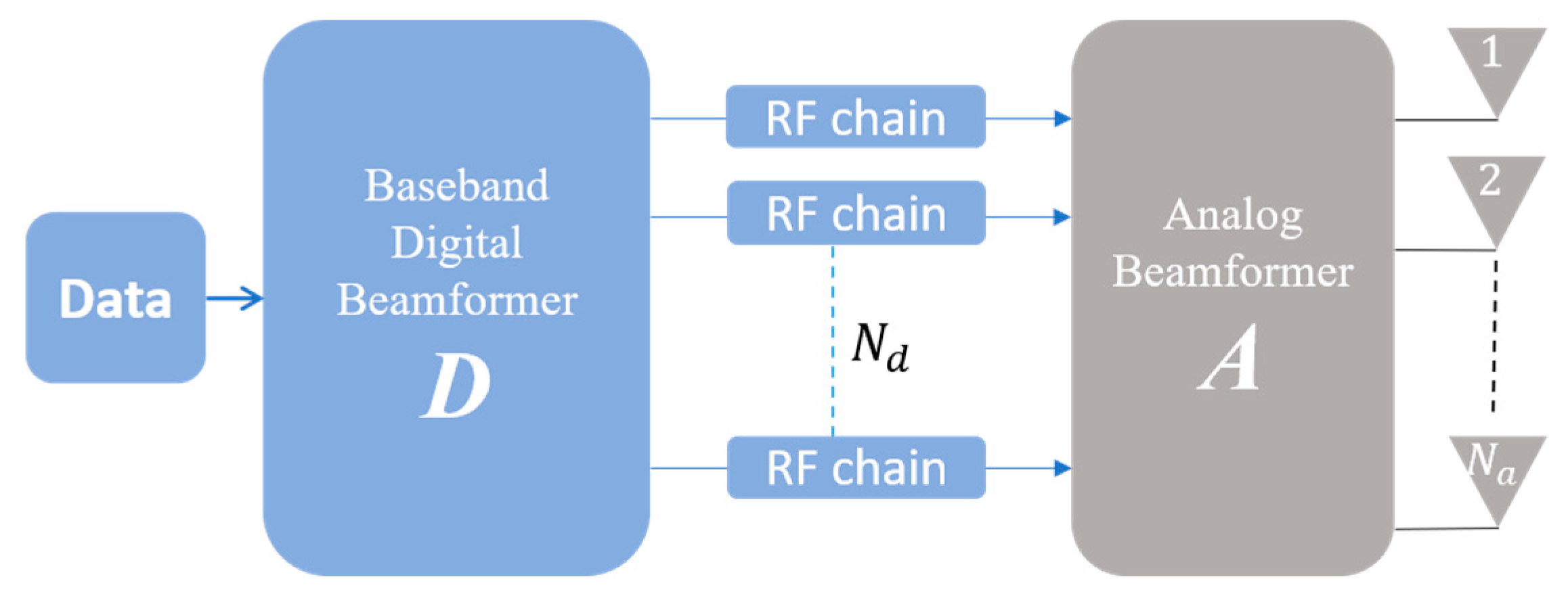
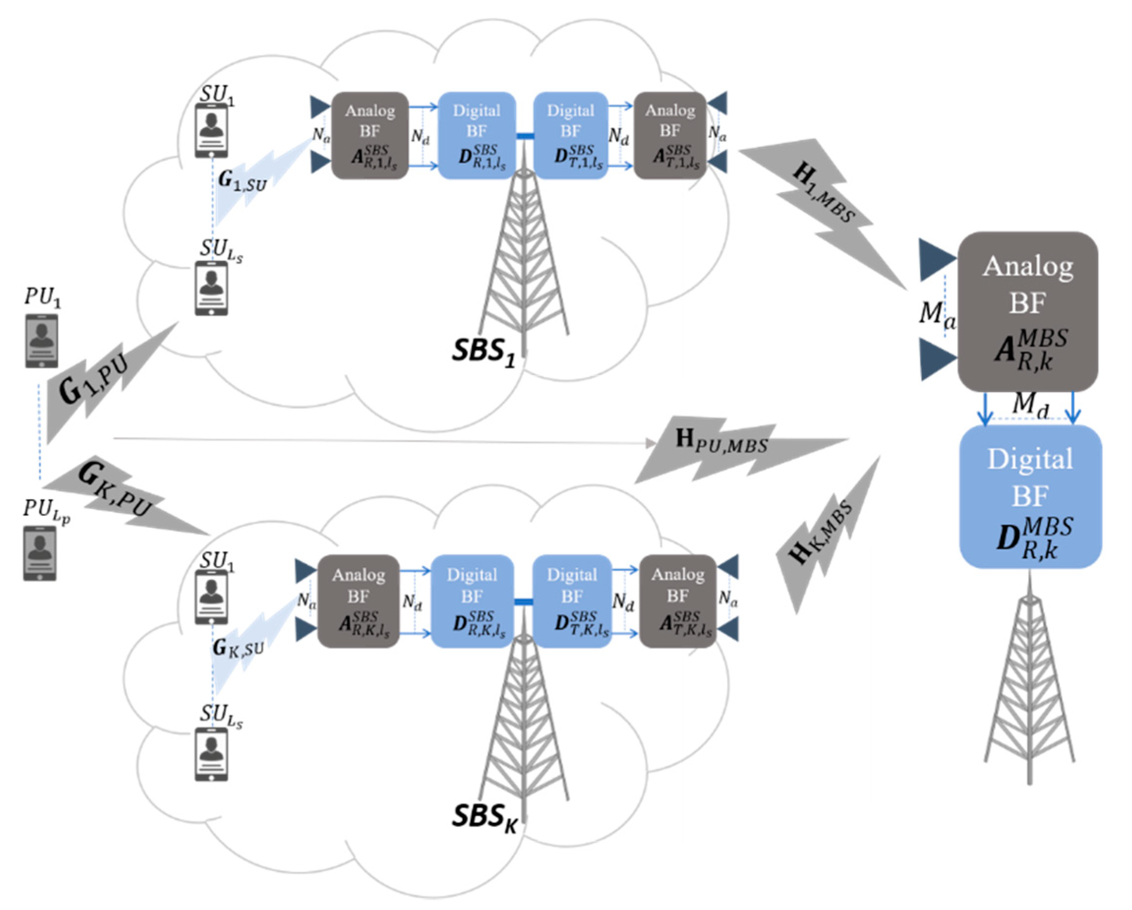
2. System Model
2.1. Access Link
2.2. Backhaul Link
2.3. End-to-End SINR and Channel Capacity
- is the user signal of the SBS,
- is the interference from the other SUs of SBS,
- is the interference from the other SBSs.
2.4. Channel Model
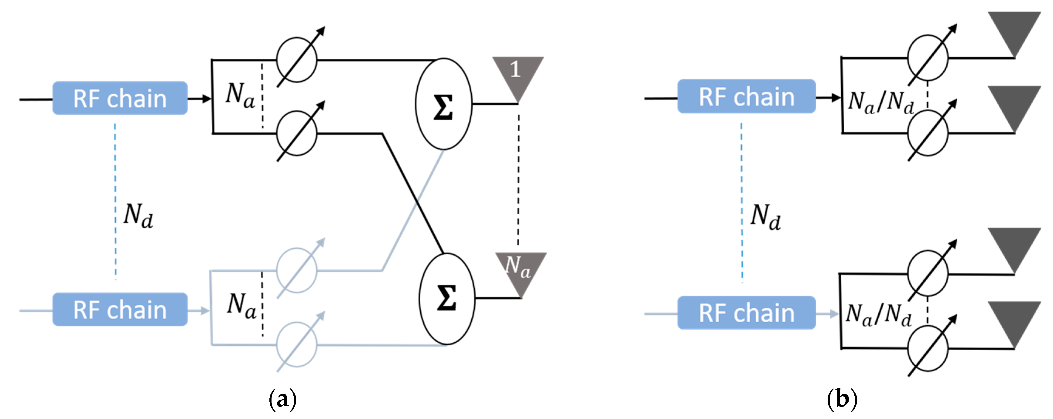
3. Proposed Hybrid Beamforming
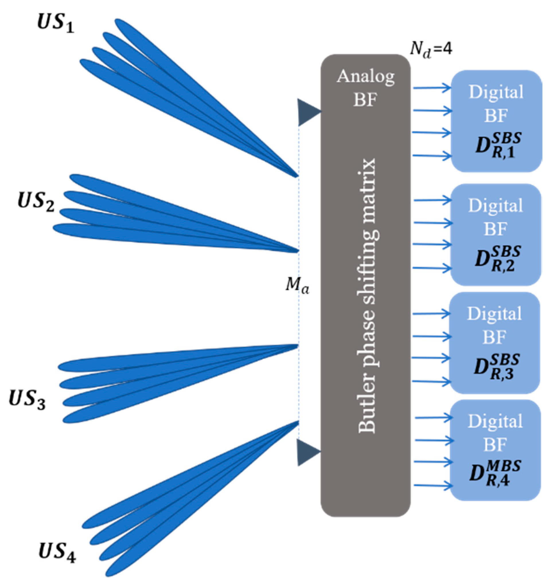
3.1. Access Link
3.2. Backhaul Link
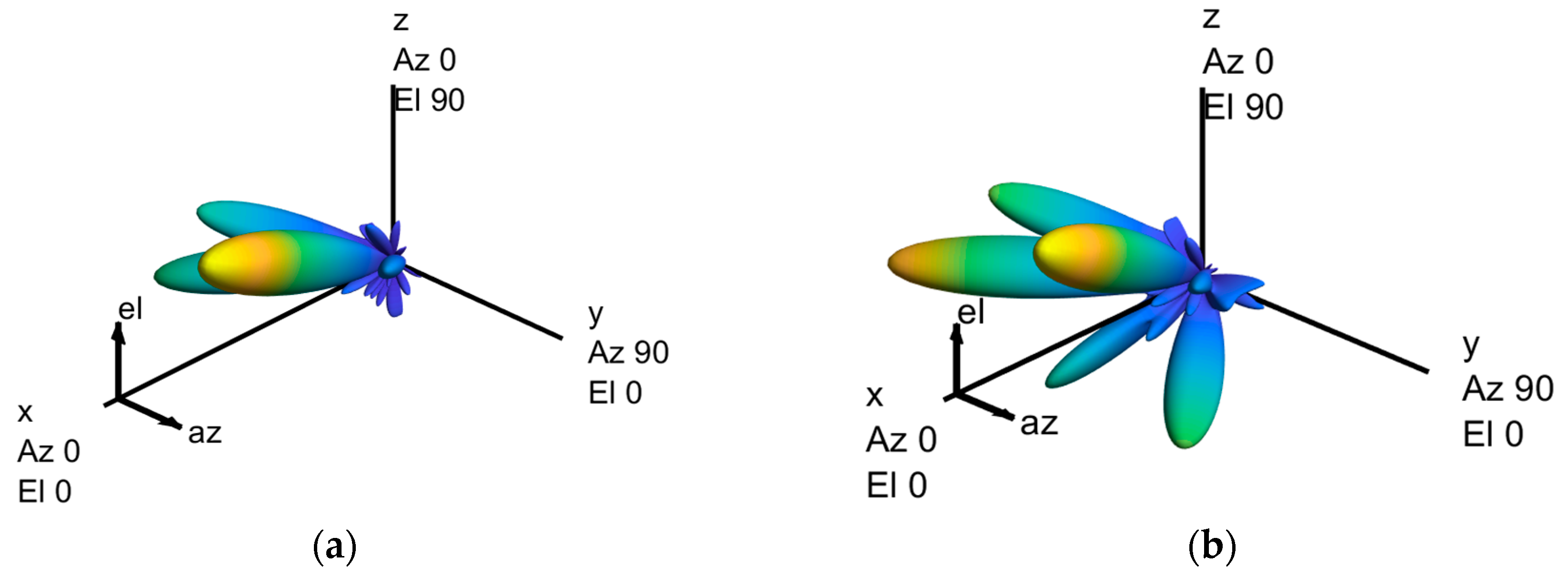
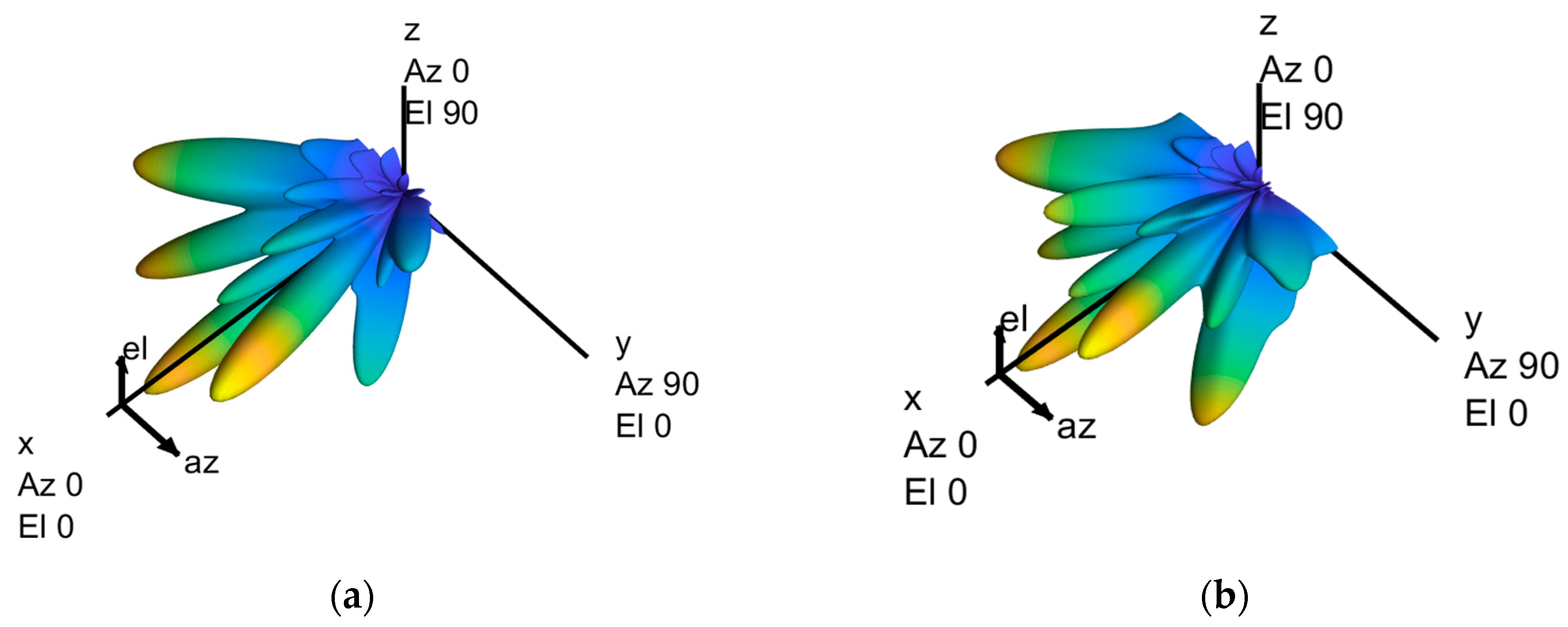
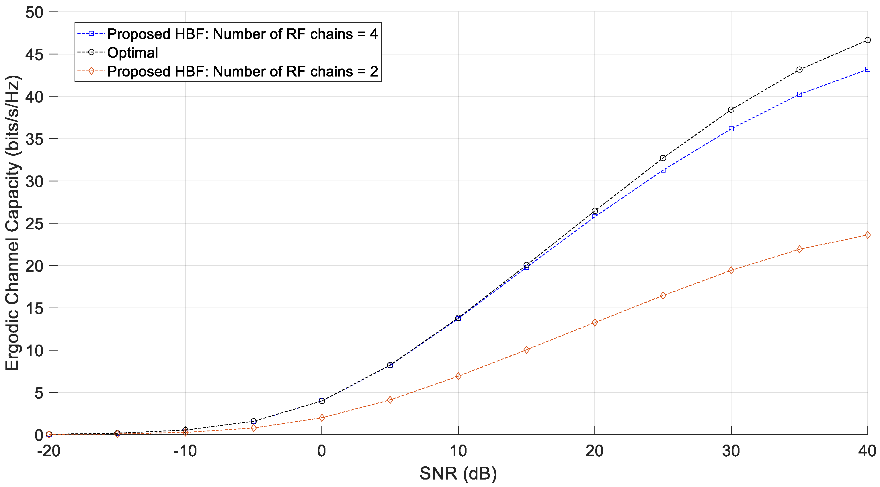
4. Simulation Results
5. Conclusions
Funding
Acknowledgments
Conflicts of Interest
References
- Siddique, U.; Tabassum, H.; Hossain, E.; Kim, D.I. Wireless backhauling of 5G small cells: Challenges and solution approaches. IEEE Wirel. Commun. 2015, 22, 22–31. [Google Scholar] [CrossRef]
- Gao, Z.; Dai, L.; Mi, D.; Wang, Z.; Imran, M.A.; Shakir, M.Z. MmWave Massive MIMO Based Wireless Backhaul for 5G Ultra-Dense Network. IEEE Wirel. Commun. 2015, 22, 13–21. [Google Scholar] [CrossRef]
- Tabassum, H.; Hamdi, S.A.; Hossai, E. Analysis of massive MIMO-enabled downlink wireless backhauling for full-duplex small cells. IEEE Trans. Commun. 2016, 64, 2354–2369. [Google Scholar] [CrossRef]
- Shariat, M.; Pateromichelakis, E.; Quddus, A.; Tafazolli, R. Joint TDD Backhaul and Access Optimization in Dense Small-Cell Networks. IEEE Trans. Veh. Technol. 2015, 64, 5288–5299. [Google Scholar] [CrossRef]
- ElSawy, H.; Hossain, E.; Kim, D.I. HetNets with cognitive small cells: User offloading and Distributed channel allocation techniques. IEEE Commun. Mag. 2013, 51, 28–36. [Google Scholar] [CrossRef]
- Yan, Z.; Zhou, W.; Chen, S.; Liu, H. Modeling and Analysis of Two-Tier HetNets with Cognitive Small Cells. IEEE Access. 2016, 5, 2904–2912. [Google Scholar] [CrossRef]
- Marzetta, T.L. Noncooperative cellular wireless with unlimited numbers of base station antennas. IEEE Trans. Wirel. Commun. 2010, 9, 3590–3600. [Google Scholar] [CrossRef]
- Rusek, F.; Persson, D.; Lau, B.; Larsson, E.; Marzetta, T.L.; Edfors, O.; Tufvesson, F. Scaling up MIMO: Opportunities and challenges with very large arrays. IEEE Signal Process. Mag. 2013, 30, 40–60. [Google Scholar] [CrossRef]
- Ngo, H.Q.; Larsson, E.G.; Marzetta, T.L. Energy and spectral efficiency of very large multiuser MIMO systems. IEEE Trans. Commun. 2013, 61, 1436–1449. [Google Scholar]
- Hoydis, J.; ten Brink, S.; Debbah, M. Massive MIMO in the UL/DL of cellular networks: How many antennas do we need? IEEE J. Sel. Areas Commun. 2013, 31, 160–171. [Google Scholar] [CrossRef]
- Hefnawi, M. Capacity-Aware Multi-User Massive MIMO for Heterogeneous Cellular Network. In Proceedings of the IEEE International Conference on Selected Topics in Mobile and Wireless Networking, Tangier, Morocco, 20–22 June 2018. [Google Scholar]
- Sohrabi, F.; Yu, W. Hybrid beamforming with finite-resolution phase shifters for large-scale MIMO systems. In Proceedings of the IEEE Workshop Signal Processing Advances in Wireless Communications, Stockholm, Sweden, 28 June–1 July 2015. [Google Scholar]
- El Ayach, O.; Rajagopal, S.; Abu-Surra, S.; Pi, Z.; Heath, R. Spatially sparse precoding in millimeter wave MIMO systems. IEEE Trans. Wirel. Commun. 2014, 13, 1499–1513. [Google Scholar] [CrossRef]
- Alkhateeb, A.; El Ayach, O.; Leus, G.; Heath, R. Channel estimation and hybrid precoding for millimeter wave cellular systems. IEEE J. Sel. Top. Signal Process. 2014, 8, 831–846. [Google Scholar] [CrossRef]
- Sohrabi, F.; Yu, W. Hybrid digital and analog beamforming design for large-scale MIMO systems. In Proceedings of the IEEE International Conference on Acoustics, Speech, Signal Process (ICASSP), Brisbane, Australia, 19–24 April 2015. [Google Scholar]
- Liang, L.; Dai, Y.; Xu, W.; Dong, X. How to approach zero-forcing under RF chain limitations in large mmwave multiuser systems? In Proceedings of the IEEE/CIC International Conference on Communications in China, Shanghai, China, 13–15 October 2014. [Google Scholar]
- Liang, L.; Xu, W.; Dong, X. Low-complexity hybrid precoding in massive multiuser MIMO systems. IEEE Wirel. Commun. 2014. [Google Scholar] [CrossRef]
- Kang, M. A comparative study on the performance of MIMO MRC systems with and without cochannel interference. IEEE Trans. Commun. 2004, 52, 1417–1425. [Google Scholar] [CrossRef]
- Sulyman, A.I.; Hefnawi, M. Adaptive MIMO Beamforming Algorithm Based on Gradient Search of the Channel Capacity in OFDMSDMA System. IEEE Commun. Lett. 2008, 12, 642–644. [Google Scholar] [CrossRef]


© 2019 by the author. Licensee MDPI, Basel, Switzerland. This article is an open access article distributed under the terms and conditions of the Creative Commons Attribution (CC BY) license (http://creativecommons.org/licenses/by/4.0/).
Share and Cite
Hefnawi, M. Hybrid Beamforming for Millimeter-Wave Heterogeneous Networks. Electronics 2019, 8, 133. https://doi.org/10.3390/electronics8020133
Hefnawi M. Hybrid Beamforming for Millimeter-Wave Heterogeneous Networks. Electronics. 2019; 8(2):133. https://doi.org/10.3390/electronics8020133
Chicago/Turabian StyleHefnawi, Mostafa. 2019. "Hybrid Beamforming for Millimeter-Wave Heterogeneous Networks" Electronics 8, no. 2: 133. https://doi.org/10.3390/electronics8020133
APA StyleHefnawi, M. (2019). Hybrid Beamforming for Millimeter-Wave Heterogeneous Networks. Electronics, 8(2), 133. https://doi.org/10.3390/electronics8020133