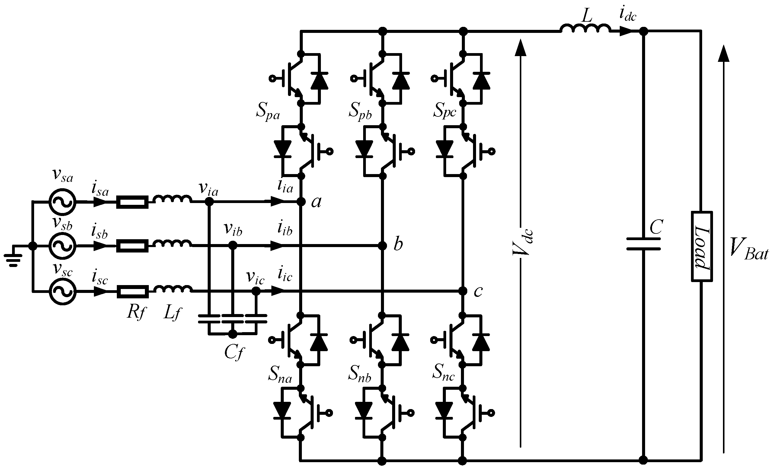
Figure 1.
AC-DC matrix converter (MC).
Figure 1.
AC-DC matrix converter (MC).
Figure 2.
Simulation waveforms of the AC-DC MC using the conventional model predictive control (MPC) (a) Three-phase current, A-phase source voltage (b) switching signal (c) load voltage, and load voltage reference.
Figure 2.
Simulation waveforms of the AC-DC MC using the conventional model predictive control (MPC) (a) Three-phase current, A-phase source voltage (b) switching signal (c) load voltage, and load voltage reference.
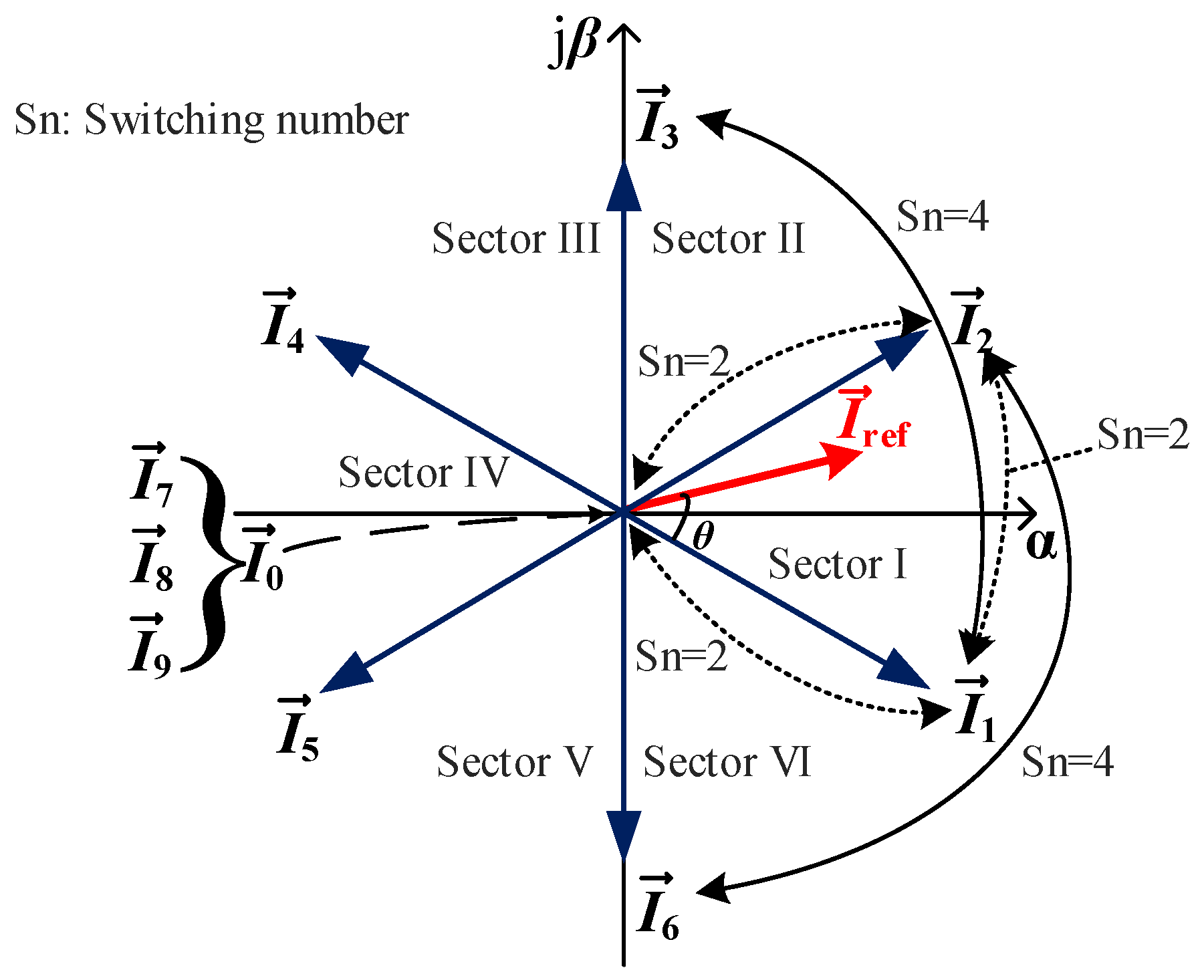
Figure 3.
Commutation space vector diagram in sector I of the AC-DC MC.
Figure 3.
Commutation space vector diagram in sector I of the AC-DC MC.
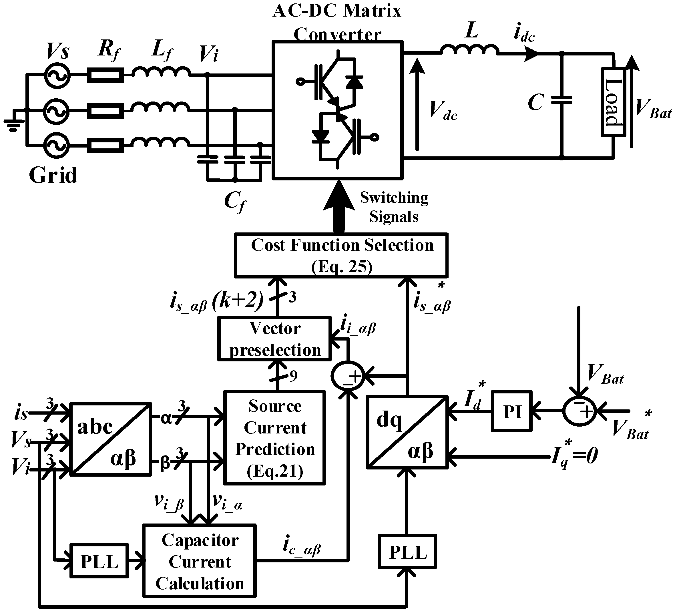
Figure 4.
Control diagram scheme of the proposed MPCC with vector selection for the AC-DC MC.
Figure 4.
Control diagram scheme of the proposed MPCC with vector selection for the AC-DC MC.
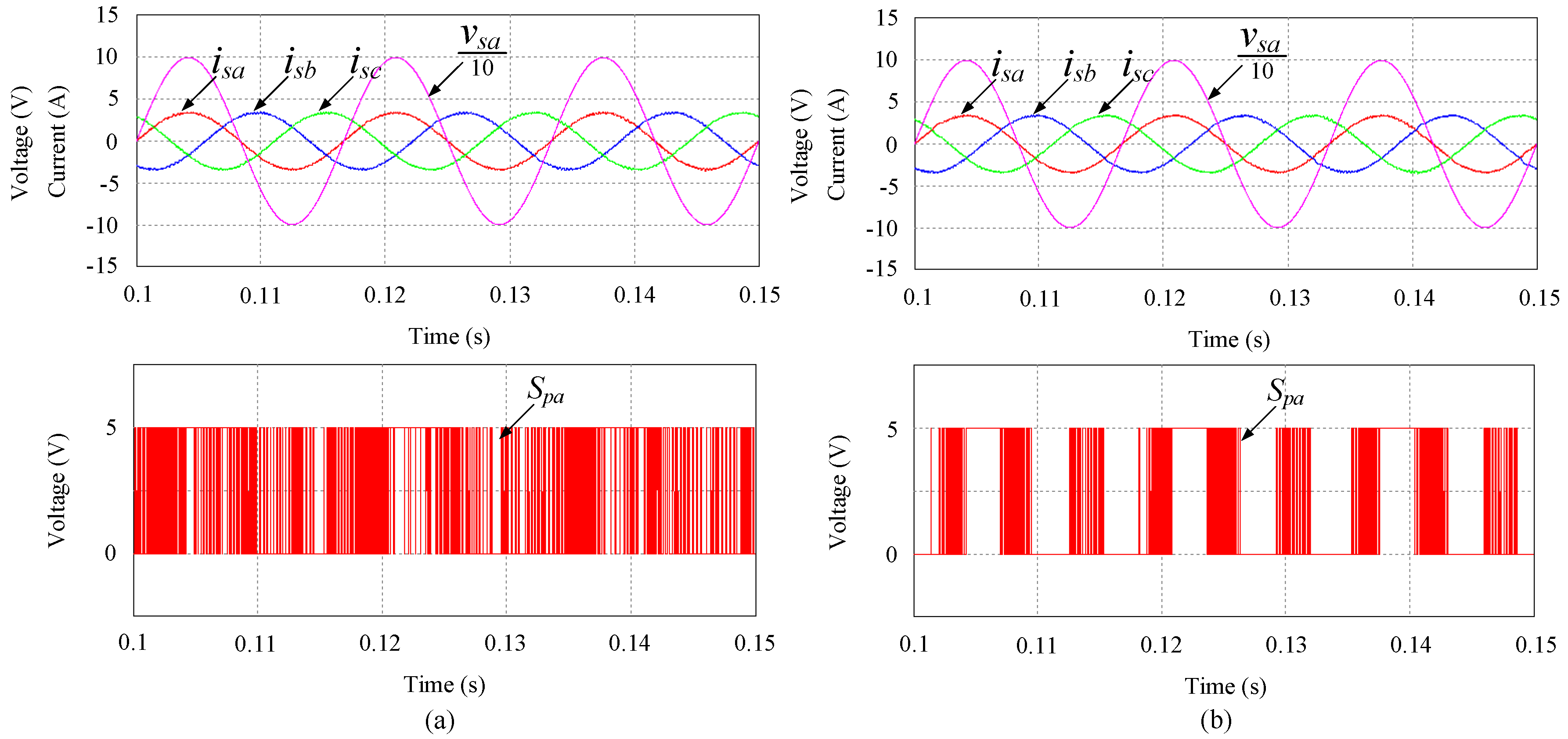
Figure 5.
Three-phase source currents, A-phase source voltage, and switching signal of Spa under different control strategies: (a) Conventional MPC (b) proposed MPCC.
Figure 5.
Three-phase source currents, A-phase source voltage, and switching signal of Spa under different control strategies: (a) Conventional MPC (b) proposed MPCC.
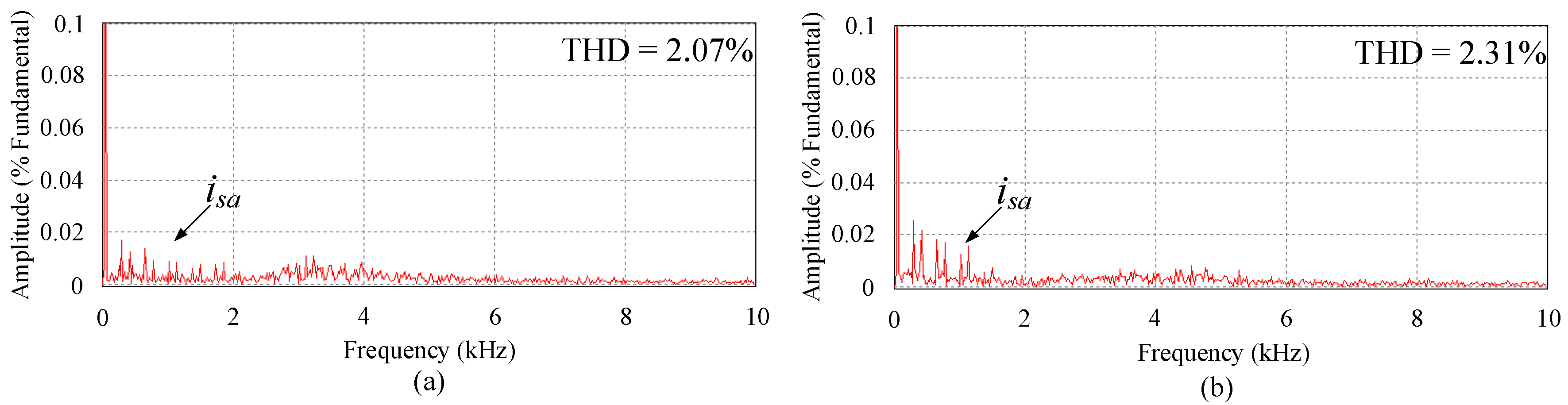
Figure 6.
Fast Fourier transform analysis of the A-phase source current under different control strategies: (a) Conventional MPC (b) proposed MPCC.
Figure 6.
Fast Fourier transform analysis of the A-phase source current under different control strategies: (a) Conventional MPC (b) proposed MPCC.
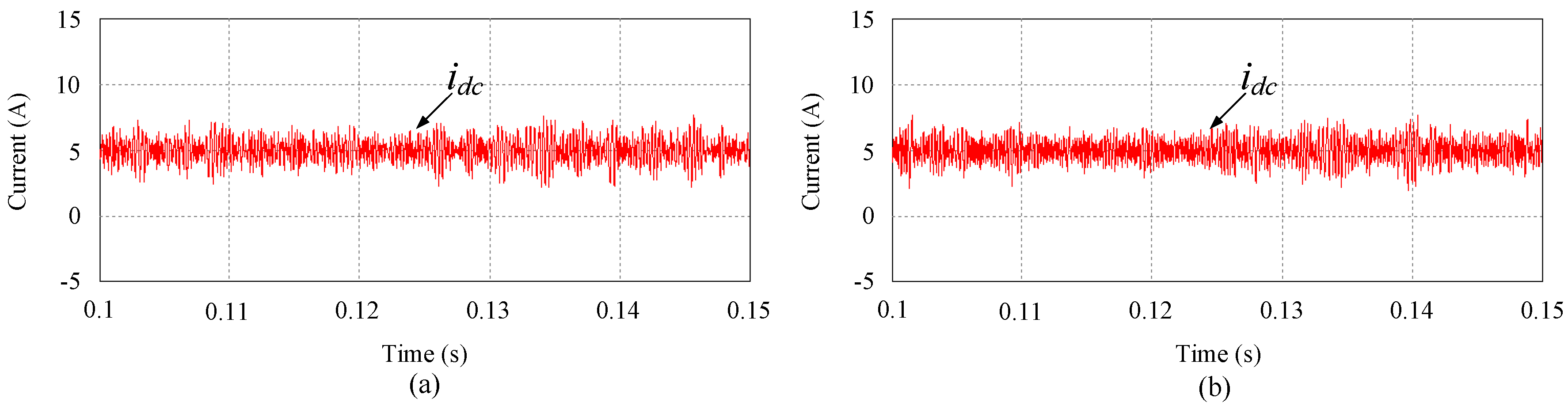
Figure 7.
DC current under different control strategies: (a) Conventional MPC (b) proposed MPCC.
Figure 7.
DC current under different control strategies: (a) Conventional MPC (b) proposed MPCC.
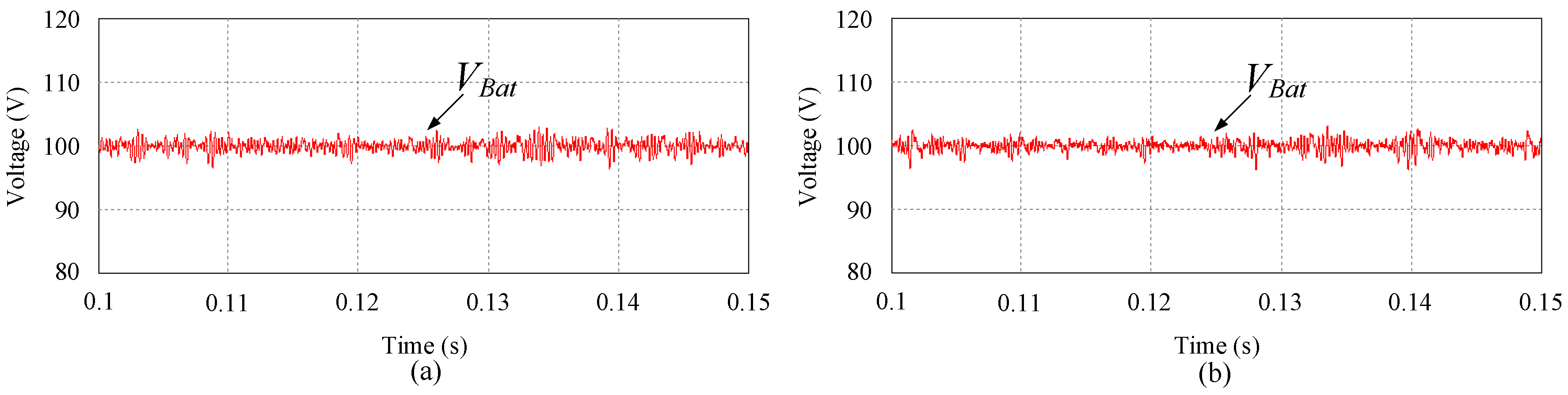
Figure 8.
Load voltage under different control strategies: (a) Conventional MPC (b) proposed MPCC.
Figure 8.
Load voltage under different control strategies: (a) Conventional MPC (b) proposed MPCC.
Figure 9.
Transient response of the three-phase source current and the A-phase source voltage under different control strategies: (a) Conventional MPC (b) proposed MPCC.
Figure 9.
Transient response of the three-phase source current and the A-phase source voltage under different control strategies: (a) Conventional MPC (b) proposed MPCC.
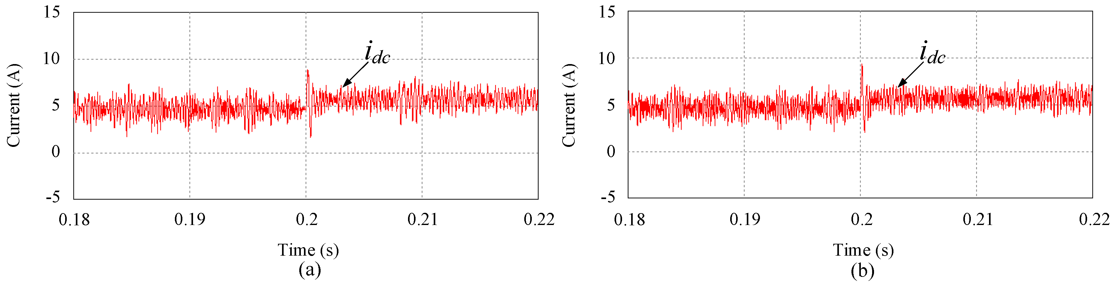
Figure 10.
Transient response of the DC current under different control strategies: (a) Conventional MPC (b) proposed MPCC.
Figure 10.
Transient response of the DC current under different control strategies: (a) Conventional MPC (b) proposed MPCC.
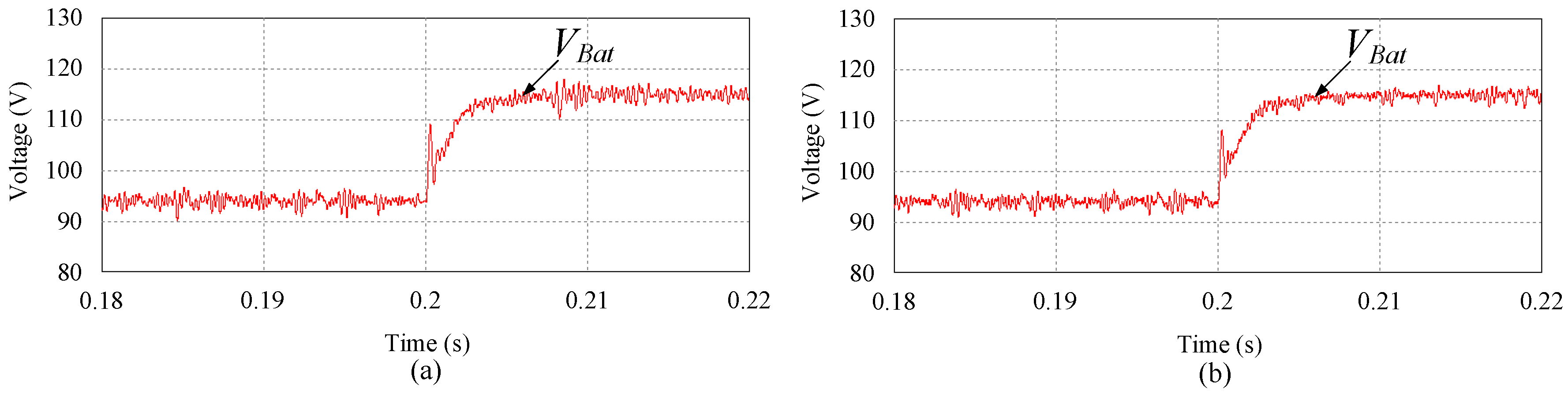
Figure 11.
Transient response of the load voltage under different control strategies: (a) Conventional MPC (b) proposed MPCC.
Figure 11.
Transient response of the load voltage under different control strategies: (a) Conventional MPC (b) proposed MPCC.
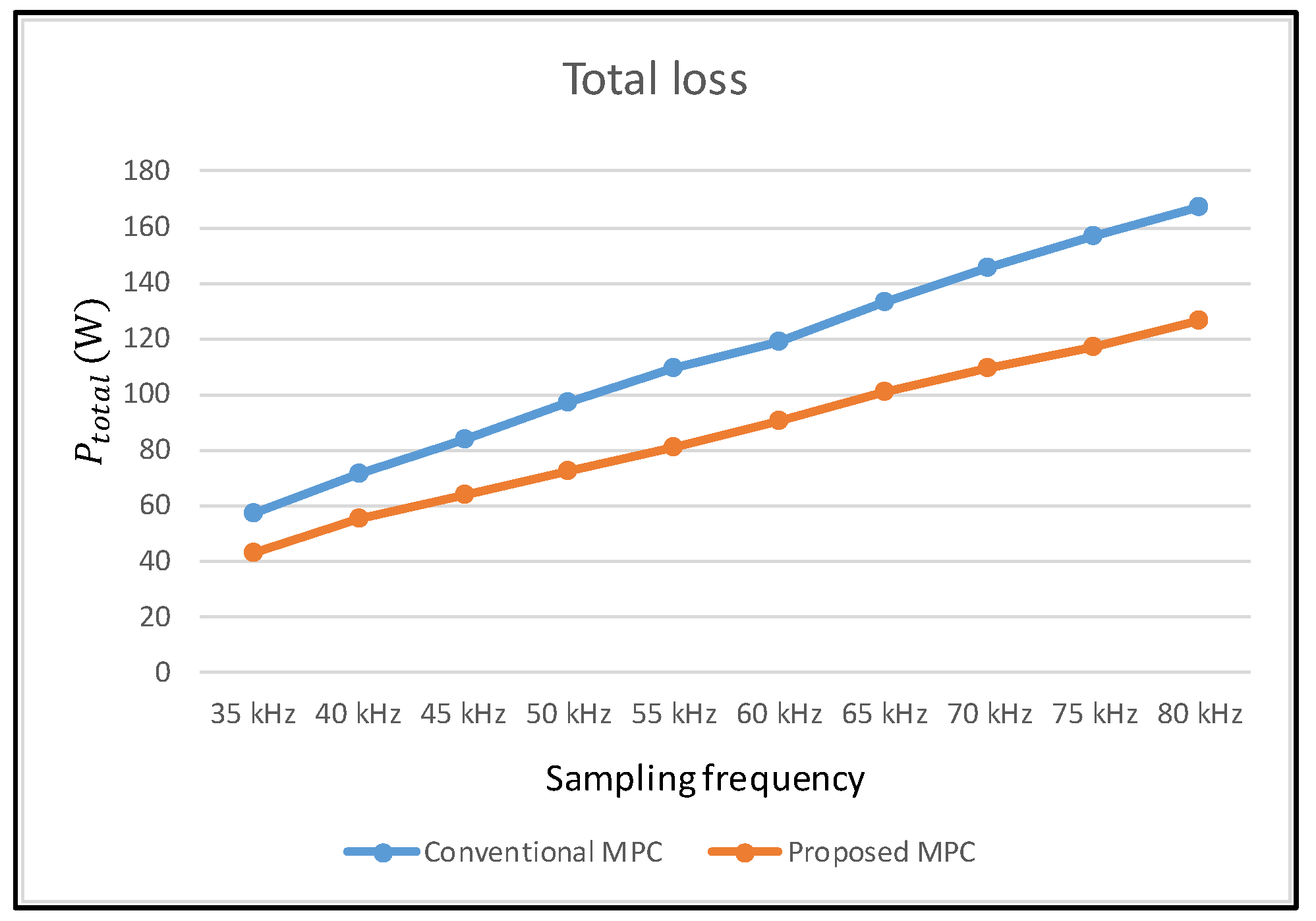
Figure 12.
Total losses of the bidirectional switches versus sampling frequency under the conventional and proposed strategies.
Figure 12.
Total losses of the bidirectional switches versus sampling frequency under the conventional and proposed strategies.
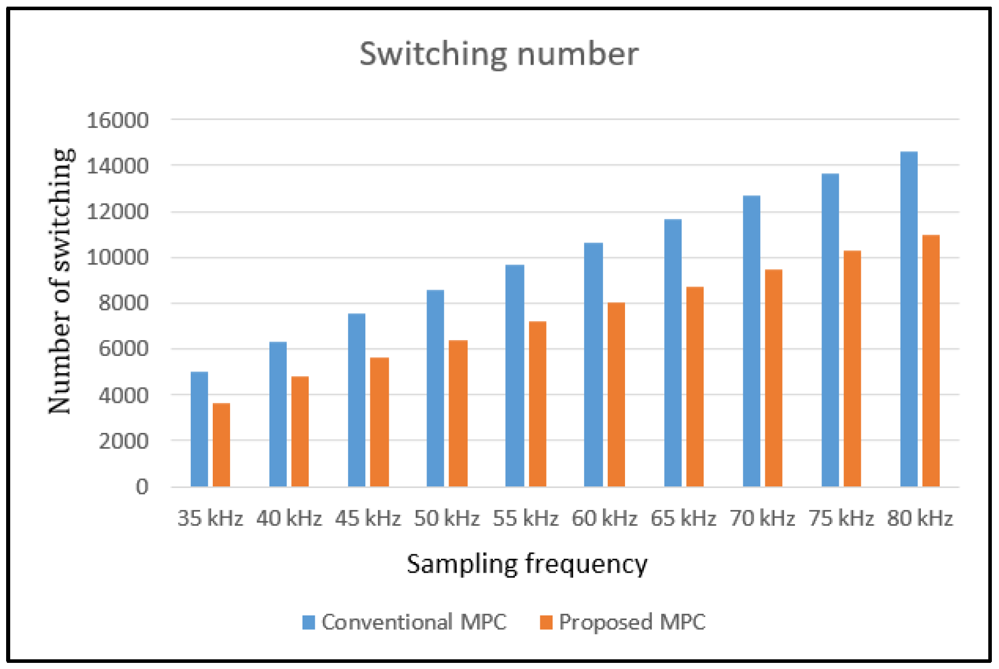
Figure 13.
Switching number of the bidirectional switches versus sampling frequency under the conventional and proposed control strategies.
Figure 13.
Switching number of the bidirectional switches versus sampling frequency under the conventional and proposed control strategies.
Figure 14.
Switching loss of the bidirectional switches versus sampling frequency under the conventional and proposed control strategies.
Figure 14.
Switching loss of the bidirectional switches versus sampling frequency under the conventional and proposed control strategies.
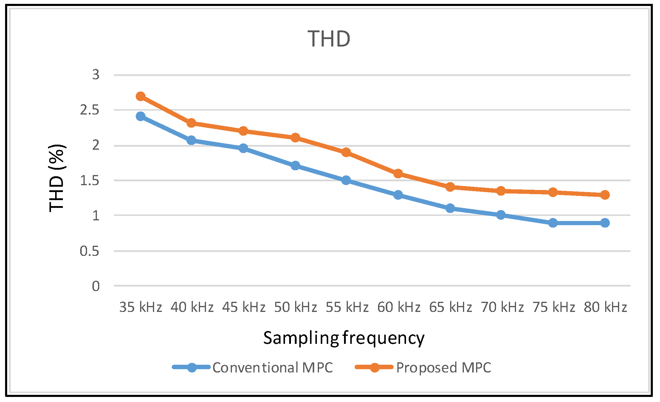
Figure 15.
Total harmonic distortion (THD) versus sampling frequency under the conventional and proposed control strategies.
Figure 15.
Total harmonic distortion (THD) versus sampling frequency under the conventional and proposed control strategies.
Figure 16.
Waveforms of A-phase source voltage, A-phase source current, load voltage, and DC current at steady state under different control strategies: (a) Conventional MPC (b) proposed MPCC.
Figure 16.
Waveforms of A-phase source voltage, A-phase source current, load voltage, and DC current at steady state under different control strategies: (a) Conventional MPC (b) proposed MPCC.
Figure 17.
Waveforms of A-phase source voltage, A-phase source current, load voltage, and DC current at transient state under different control strategies: (a) Conventional MPC (b) proposed MPCC.
Figure 17.
Waveforms of A-phase source voltage, A-phase source current, load voltage, and DC current at transient state under different control strategies: (a) Conventional MPC (b) proposed MPCC.
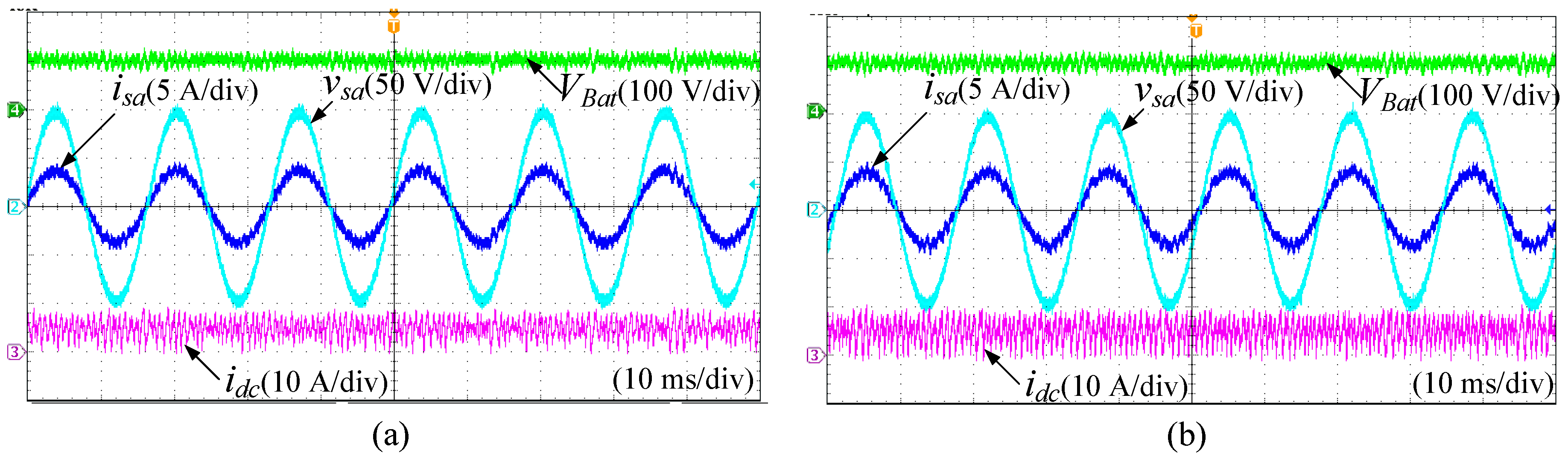
Figure 18.
Experimental waveforms of A-phase source voltage, A-phase source current, THD of A-phase source current, and switching signal of A-phase upper-arm switch under different control strategies: (a) Conventional MPC (b) proposed MPCC.
Figure 18.
Experimental waveforms of A-phase source voltage, A-phase source current, THD of A-phase source current, and switching signal of A-phase upper-arm switch under different control strategies: (a) Conventional MPC (b) proposed MPCC.
Table 1.
Summary of the selected vectors in different sectors of the AC-DC matrix converter (MC) using the conventional model predictive control (MPC).
Table 1.
Summary of the selected vectors in different sectors of the AC-DC matrix converter (MC) using the conventional model predictive control (MPC).
| Sector | Selected Vectors | Sum |
|---|
| | | | | | |
|---|
| 1 | 54.5 | 28.8 | 10.2 | 0 | 0 | 1 | 16.8 | 111.3 |
| 2 | 1.2 | 53.8 | 29 | 9.7 | 0 | 0 | 17.7 | 111.4 |
| 3 | 0 | 0.7 | 53.5 | 29.8 | 8.7 | 0 | 18.3 | 111 |
| 4 | 0 | 0 | 1 | 54.5 | 28.8 | 10.5 | 16.5 | 111.3 |
| 5 | 10.2 | 0 | 0 | 1.2 | 54 | 28.2 | 17.8 | 111.4 |
| 6 | 29.8 | 8.8 | 0 | 0 | 1.2 | 53.3 | 18 | 111.1 |
| Sum | 95.7 | 92.1 | 93.7 | 95.2 | 92.7 | 93 | 105.1 | 667.5 |
Table 2.
Summary of the selected vectors in different sectors of the voltage source rectifier (VSR) using the conventional MPC.
Table 2.
Summary of the selected vectors in different sectors of the voltage source rectifier (VSR) using the conventional MPC.
| Sector | Selected Vectors | Sum |
|---|
| | | | | | |
|---|
| 1 | 49 | 37 | 0 | 0 | 0 | 4.2 | 21 | 111.2 |
| 2 | 1.8 | 52.2 | 32.7 | 0 | 0 | 0 | 23.8 | 110.5 |
| 3 | 0 | 1.2 | 52.8 | 33.5 | 1 | 0 | 22.8 | 111.3 |
| 4 | 0 | 0 | 4.2 | 48.7 | 38.7 | 0 | 19.5 | 111.2 |
| 5 | 0 | 0 | 0 | 0.8 | 52 | 35.3 | 23.8 | 111.9 |
| 6 | 34.5 | 0.2 | 0 | 0 | 1.3 | 51.5 | 23.7 | 111.2 |
| Sum | 85.3 | 90.6 | 89.7 | 83.1 | 93 | 91 | 134.6 | 667.3 |
Table 3.
Percentage of the selected vectors in different sectors of the AC-DC MC using the conventional MPC.
Table 3.
Percentage of the selected vectors in different sectors of the AC-DC MC using the conventional MPC.
| Sector | Selected Vectors | Sum |
|---|
| | | | | | |
|---|
| 1 | 49% | 25.9% | 9.2% | 0 | 0 | 0.9% | 15% | 100% |
| 2 | 1.1% | 48.3% | 26% | 8.7% | 0 | 0 | 15.9% | 100% |
| 3 | 0 | 0.6% | 48.2% | 26.8% | 7.8% | 0 | 16.6% | 100% |
| 4 | 0 | 0 | 0.9% | 49% | 25.9% | 9.4% | 14.8% | 100% |
| 5 | 9.2% | 0 | 0 | 1.1% | 48.5% | 25.3% | 15.9% | 100% |
| 6 | 26.8% | 7.9% | 0 | 0 | 1.1% | 48% | 16.2% | 100% |
Table 4.
Percentage of the selected vectors in different sectors of the VSR using the conventional MPC.
Table 4.
Percentage of the selected vectors in different sectors of the VSR using the conventional MPC.
| Sector | Selected Vectors | Sum |
|---|
| | | | | | |
|---|
| 1 | 44.1% | 33.3% | 0 | 0 | 0 | 3.8% | 18.8% | 100% |
| 2 | 1.6% | 47.2% | 29.6% | 0 | 0 | 0 | 21.6% | 100% |
| 3 | 0 | 1.1% | 47.4% | 30.1% | 0.9% | 0 | 20.5% | 100% |
| 4 | 0 | 0 | 3.7% | 43.8% | 34.8% | 0 | 17.7% | 100% |
| 5 | 0 | 0 | 0 | 0.7% | 46.5% | 31.5% | 21.3% | 100% |
| 6 | 31% | 0.2% | 0 | 0 | 1.2% | 46.3% | 21.% | 100% |
Table 5.
Switching numbers of the commutations between different vectors in different sectors of the AC-DC MC using the conventional MPC.
Table 5.
Switching numbers of the commutations between different vectors in different sectors of the AC-DC MC using the conventional MPC.
| Commutations | Sector | Sum |
|---|
| | | | | |
|---|
| 56 | 26 | 0 | 0 | 0 | 4 | 86 |
| 44 | 2 | 0 | 0 | 0 | 0 | 46 |
| 0 | 0 | 0 | 0 | 0 | 0 | 0 |
| 0 | 0 | 0 | 0 | 120 | 0 | 120 |
| 6 | 0 | 0 | 0 | 0 | 120 | 126 |
| 46 | 0 | 0 | 0 | 0 | 0 | 46 |
| 8 | 50 | 0 | 0 | 0 | 0 | 58 |
| 0 | 8 | 0 | 0 | 0 | 0 | 8 |
| 0 | 0 | 0 | 0 | 0 | 0 | 0 |
| 0 | 0 | 0 | 0 | 0 | 104 | 104 |
| 10 | 42 | 0 | 0 | 0 | 0 | 52 |
| 0 | 4 | 58 | 0 | 0 | 0 | 62 |
| 0 | 0 | 88 | 0 | 0 | 0 | 88 |
| 0 | 0 | 4 | 0 | 0 | 0 | 4 |
| 0 | 6 | 40 | 0 | 0 | 0 | 46 |
| 0 | 0 | 4 | 52 | 0 | 0 | 56 |
| 0 | 0 | 0 | 116 | 0 | 0 | 116 |
| 0 | 0 | 2 | 24 | 0 | 0 | 26 |
| 0 | 0 | 0 | 4 | 52 | 0 | 56 |
| 0 | 0 | 0 | 8 | 48 | 0 | 56 |
| 0 | 0 | 0 | 2 | 4 | 36 | 42 |
| Sum | 170 | 138 | 196 | 206 | 224 | 264 | 1198 |
Table 6.
Switching numbers of the commutations between different vectors in different sectors of the VSR using the conventional MPC.
Table 6.
Switching numbers of the commutations between different vectors in different sectors of the VSR using the conventional MPC.
| Commutations | Sector | Sum |
|---|
| | | | | |
|---|
| 80 | 2 | 0 | 0 | 0 | 4 | 86 |
| 0 | 0 | 0 | 0 | 0 | 0 | 0 |
| 0 | 0 | 0 | 0 | 0 | 0 | 0 |
| 0 | 0 | 0 | 0 | 0 | 0 | 0 |
| 2 | 0 | 0 | 0 | 0 | 64 | 66 |
| 66 | 2 | 0 | 0 | 0 | 42 | 110 |
| 0 | 78 | 4 | 0 | 0 | 0 | 82 |
| 0 | 0 | 0 | 0 | 0 | 0 | 0 |
| 0 | 0 | 0 | 0 | 0 | 0 | 0 |
| 0 | 0 | 0 | 0 | 0 | 8 | 8 |
| 30 | 62 | 0 | 0 | 0 | 0 | 92 |
| 0 | 0 | 72 | 10 | 0 | 0 | 82 |
| 0 | 0 | 0 | 12 | 0 | 0 | 12 |
| 0 | 0 | 0 | 0 | 0 | 0 | 0 |
| 0 | 28 | 56 | 0 | 0 | 0 | 84 |
| 0 | 0 | 2 | 82 | 4 | 0 | 88 |
| 0 | 0 | 0 | 0 | 0 | 0 | 0 |
| 0 | 0 | 36 | 52 | 0 | 0 | 88 |
| 0 | 0 | 0 | 0 | 68 | 0 | 68 |
| 0 | 0 | 0 | 26 | 68 | 0 | 94 |
| 2 | 0 | 0 | 0 | 28 | 56 | 86 |
| Sum | 180 | 172 | 170 | 182 | 168 | 174 | 1046 |
Table 7.
Summary of the selected vectors in different sectors of the proposed MPC for AC-DC MC.
Table 7.
Summary of the selected vectors in different sectors of the proposed MPC for AC-DC MC.
| Sector | Selected Vectors |
|---|
| 1 | |
| 2 | |
| 3 | |
| 4 | |
| 5 | |
| 6 | |
Table 8.
Parameters of the AC-DC MC.
Table 8.
Parameters of the AC-DC MC.
| Parameters | Value |
|---|
| Source phase voltage () | 100 V |
| Source frequency () | 60 Hz |
| Input filter inductance () | 5 mH |
| Input filter capacitance () | 60 µF |
| Input filter resistance () | 0.1 Ω |
| Output filter inductance () | 2 mH |
| Output filter capacitance () | 40 µF |
| Load resistance () | 20 Ω |
| Sampling frequency () | 40 kHz |
| Load voltage reference () | 100 V |
Table 9.
Summary of vector selection in different sectors of the proposed MPC.
Table 9.
Summary of vector selection in different sectors of the proposed MPC.
| Sector | Selected vectors | Sum |
|---|
| | | | | | |
|---|
| 1 | 45.3 | 38.2 | 0 | 0 | 0 | 0 | 27.3 | 110.8 |
| 2 | 0 | 45.8 | 38.3 | 0 | 0 | 0 | 27.5 | 111.6 |
| 3 | 0 | 0 | 45 | 38.5 | 0 | 0 | 27.5 | 111 |
| 4 | 0 | 0 | 0 | 45 | 38.5 | 0 | 28.2 | 111.7 |
| 5 | 0 | 0 | 0 | 0 | 45 | 38 | 28 | 111 |
| 6 | 37.5 | 0 | 0 | 0 | 0 | 45.8 | 28.2 | 111.5 |
| Sum | 82.8 | 84 | 83.3 | 83.5 | 83.5 | 83.8 | 166.7 | 667.6 |
Table 10.
Number of switchings in different sectors of different switches under the conventional MPC.
Table 10.
Number of switchings in different sectors of different switches under the conventional MPC.
| Sector | Number of Switching | Sum |
|---|
| | | | | |
|---|
| 1 | 12 | 12 | 0 | 13 | 35 | 27 | 99 |
| 2 | 31 | 32 | 0 | 25 | 0 | 25 | 113 |
| 3 | 18 | 24 | 8 | 37 | 0 | 36 | 123 |
| 4 | 7 | 33 | 29 | 15 | 16 | 0 | 100 |
| 5 | 23 | 0 | 23 | 26 | 26 | 0 | 98 |
| 6 | 33 | 0 | 33 | 12 | 22 | 10 | 110 |
| Sum | 124 | 101 | 93 | 128 | 99 | 98 | 643 |
Table 11.
Number of switchings in different sectors of different switches under the proposed MPCC.
Table 11.
Number of switchings in different sectors of different switches under the proposed MPCC.
| Sector | Number of Switching | Sum |
|---|
| | | | | |
|---|
| 1 | 0 | 0 | 0 | 25 | 31 | 25 | 81 |
| 2 | 33 | 26 | 26 | 0 | 0 | 0 | 85 |
| 3 | 0 | 0 | 0 | 26 | 25 | 33 | 84 |
| 4 | 21 | 29 | 25 | 0 | 0 | 0 | 75 |
| 5 | 0 | 0 | 0 | 31 | 25 | 23 | 79 |
| 6 | 25 | 24 | 33 | 0 | 0 | 0 | 82 |
| Sum | 79 | 79 | 84 | 82 | 81 | 81 | 486 |


