Article

Compact Wearable Meta Materials Antennas for Energy Harvesting Systems, Medical and IOT Systems

Department of Electrical Engineering, Kinneret and Ort Braude Colleges, Hemek Hayarden 15132, Israel
Electronics 2019, 8(11), 1340; https://doi.org/10.3390/electronics8111340
Submission received: 4 October 2019 / Revised: 6 November 2019 / Accepted: 9 November 2019 / Published: 13 November 2019
(This article belongs to the Section Microwave and Wireless Communications)

Abstract

:
Demand for green technologies and green energy is in continuous growth in the last decade. Compact efficient radiators are very important for energy harvesting portable systems. Small antennas have low efficiency. The efficiency of communication and energy harvesting systems may increase by using efficient passive and active antennas. The system dynamic range may be improved by connecting amplifiers to the printed antenna feed line. Design, design considerations, computed and measured results of wearable meta-materials antennas with high efficiency for energy harvesting applications are presented in this paper. The antennas electrical parameters on human body were analyzed by using commercial full-wave software. The wearable antennas are compact and flexible and are 1.6 mm thick. The directivity and gain of the antennas with Split-ring resonators (SRR), is higher by 2 dB to 3 dB than the antennas without SRR. The resonant frequency of the antennas without SRR is higher by 5% to 10% than the antennas with SRR.

1. Introduction

Wearable medical, 5G and IOT systems cannot function without using batteries and power cords. Energy harvesting systems may eliminate both the need to replace batteries every day and the usage of power cords. In order to harvest as much free space electromagnetic energy as possible, it is important to collect the electromagnetic energy from several communication systems. Due to low RF power densities, efficient antennas are crucial. Several methods to produce green electricity from light, heat, radio waves and vibration have been developed [1,2,3]. Several printed antennas were employed for harvesting energy applications [1,2,3,4,5,6]. Patch and other printed antennas are used in RF Body Area Network (BAN), communication and medical systems [7,8,9,10,11,12,13,14,15,16,17,18,19,20,21,22,23,24,25,26,27]. However, compact printed antennas such as these have low efficiency. Compact wearable devices and antennas have been presented in several papers in the last decade, see [1,2,3,4,5]. Meta material structures may be used to design compact antennas with high efficiency for wearable systems and energy harvesting systems, [6,7,8,9,10,11,12,13,14,15]. Meta material is a periodic material that derives its properties from the material structure rather than from its components. Periodic split ring resonators (SRRs) and metallic posts structures may be used to design materials with specific dielectric constant and permeability as presented in [6,7,8,9,10,11,12,13,14,15]. For example, artificial materials with negative dielectric permittivity were presented in [6]. A quasi-analytical and self-consistent model to compute the polarizabilities of split ring resonators (SRRs) is presented in [8]. An experimental setup is also proposed for measuring the magnetic polarizability of SRR structures. Experimental data are compared with theoretical results computed following the proposed model as presented in [8]. The design of a novel compact microstrip patch antenna whose size is reduced via the use of metamaterials is presented in [11]. However, the authors claim that the bandwidth and the antenna gain is the same as a regular patch antenna. A compact transmission-line metamaterial antenna with extended bandwidth is presented in [12]. The antenna consists of two transmission-line arms that resonate at different frequencies. Each arm is a microstrip transmission-line loaded with five spiral inductors. The antenna measured radiation efficiency is 65.8% at 3.3 GHz. The antenna bandwidth is 3%. The estimated measured directivity is 2.6 dBi and the measured peak gain is 0.79 dBi.
In the last decade, the idea of employing free space energy in the forms of heat, light, vibration, electromagnetic waves, muscle motion and other types of energy, has become useful and attractive. The number of methods to produce electricity from these different types of energy sources have also developed [28,29,30]. In this paper, meta-materials are employed to develop antennas with around 90% efficiency for medical, IOT and energy harvesting systems. The computed and measured bandwidth of the wearable antenna with SRR and metallic strips for energy harvesting and medical applications is around 50% for VSWR (Voltage Standing Wave Ratio) of 2.3:1. The electrical properties of the antennas were computed by considering the electrical properties of human body tissues. These electrical properties of human tissues were presented in several papers such as [16,17].

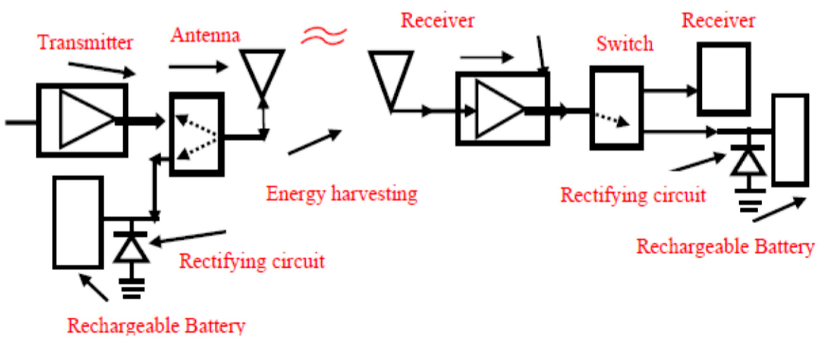
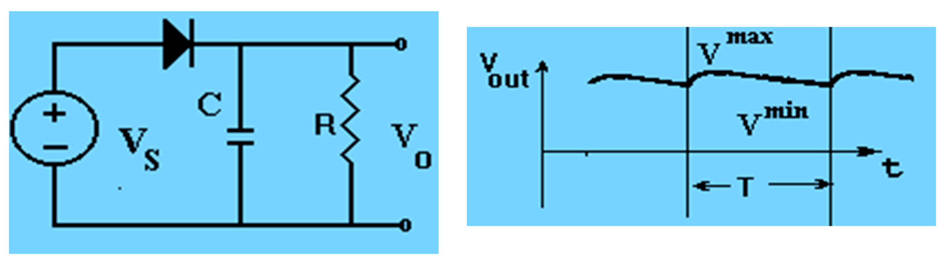
2. Energy Harvesting Systems

There is a significant increase in the amount of electromagnetic energy in the air in the last decade. In electromagnetic energy harvesting systems, radio waves propagating in free space are captured, stored and used as green energy to charge batteries, amongst other purposes. The amount of RF waves in the air in 2013 was around 1.5 Exa-bytes per month. In comparison, the amount of RF waves in the air in 2017 was 11 Exa-bytes per month. In the last decade, there has been a continuous increase in RF traffic in the air. However, the amount of RF energy does not always correlate with the data. In 2010, one could perform fifteen million computations per KWh. In 2019, one can perform more computations per KWh. Modern communication devices consume more energy and need to be charged frequently. Commercial communication systems operate in the frequencies from 700 MHz to 2700MHz. Medical systems operate in the frequencies from 200 MHz to 1200MHz. WLAN systems operate in the frequencies from 5.2 GHz to 6 GHz. One may collect electromagnetic energy from 0.2 GHz up to 6 GHz. Energy sources used in harvesting systems are listed in Table 1. Harvested energy from indoor microwave energy sources is around 0.1 µW/cm2. Harvested power from RF energy sources in malls and stadiums may increase to around 1mW/cm2. RF energy is inversely proportional to distance and therefore decreases as the distance from the source is increased.
The harvesting energy system operates as a dual mode energy harvesting system that can charge the battery when the switch is connected to the harvesting system. The receiving system employs a low noise amplifier to improve the system SNR. The Low Noise Amplifier (LNA), DC bias voltages are supplied by the receiving system DC unit and then supplied continuously to the system. The energy harvesting system consists of radiator, a rectifying circuit and a rechargeable battery, as presented in Figure 1. Electromagnetic AC energy is converted to direct current by using a rectifier that may be a half-wave or a full-wave rectifier. A half-wave voltage rectifier is shown in Figure 2. A half-wave rectifier operates only during the voltage positive half cycle. This rectifier allows only one half of the AC voltage to pass through the load. The rectifier output DC voltage, V O D C , is given in Equation (1).
The ripple voltage is given in Equation (2). T, the wave period time, should be greater than the time constant τ , where τ = R C T .
The rectifier output voltage is flattened by connecting a capacitor in shunt to the resistor as presented in Figure 3. The half-wave rectifier efficiency is 40.6%, as given in Equation (3). DC power supplies uses diode bridge full-wave rectifier that consists of four diodes. D1 through D4, as shown in in Figure 4, connected to form a bridge. During the positive input half cycle, terminal A will be positive and terminal B will be negative. Diodes D1 and D2 will become forward biased and D3 and D4 will be reverse biased. A capacitor is used to improve the flatness of the rectifier output voltage variation as function of time, as shown in Figure 5. The capacitor can be a voltage-controlled diode, varactor. Varactors are voltage variable capacitors designed to provide electronic tuning of electrical devices. The output voltage ripple (see Equation (2)) of the improved rectifier may be tuned as a function of the frequency of the received signal or of the load resistance, R. The varactor bias voltage is varied automatically to get the lowest output voltage ripple. The rectifier output DC voltage V O D C = 2 V m / π
V O , D C = 1 2 π 0 2 π V O M A X sin ( ω t ) d ( ω t ) ; ω = 2 π f V O = V S V D O N V S ; V O M A X = V m V O D C = V m / π
V r i p p l e = V r = V m a x V m i n = V D C f C R
η = DC   output   power AC   input   power = ( I m π ) 2 R ( I m 2 ) 2 ( R + r f ) ~ 0.406
The rectifier output voltage may be improved by connecting a capacitor in shunt to the resistor.
η = DC   output   power AC   input   power = ( 2 I m π ) 2 R ( I m 2 ) 2 ( R + r f ) ~ 0.812
The full wave rectifier efficiency is 81.2% as presented in Equation (4). The diode in the rectifier circuit can be a Schottky diode. Schottky diodes are semiconductor diodes that have a fast switching action and a low forward voltage drop. Usually the voltage drops from 0.2 V to 0.4 V across the diode terminals, when current flows through the diode. This lower voltage drop provides higher switching speed and better system efficiency. A wearable harvesting system and a wearable battery charger attached to the patient shirt are presented in Figure 6.

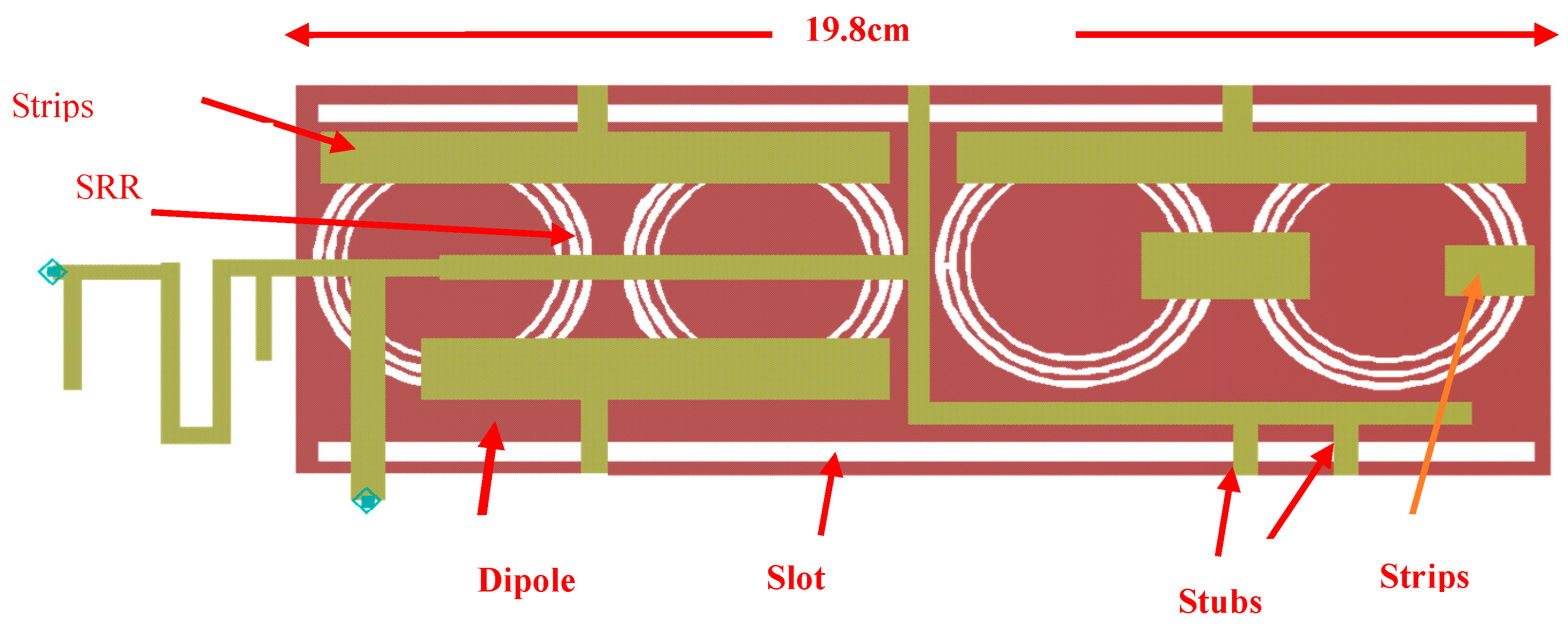
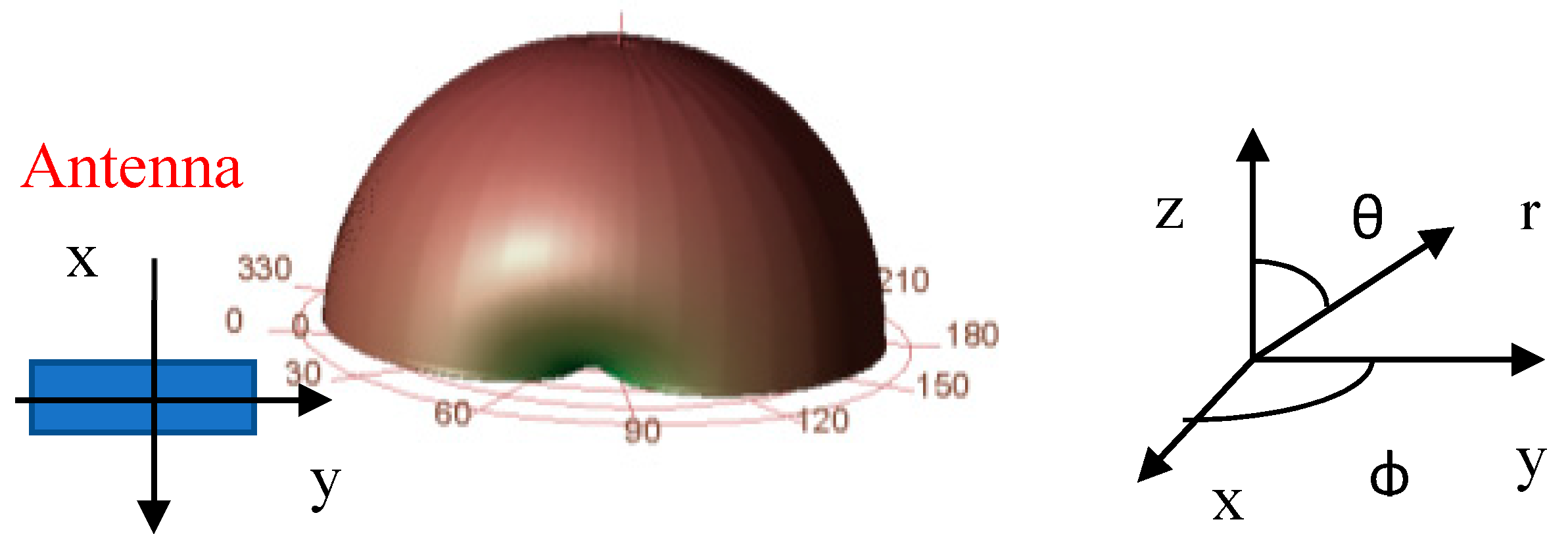
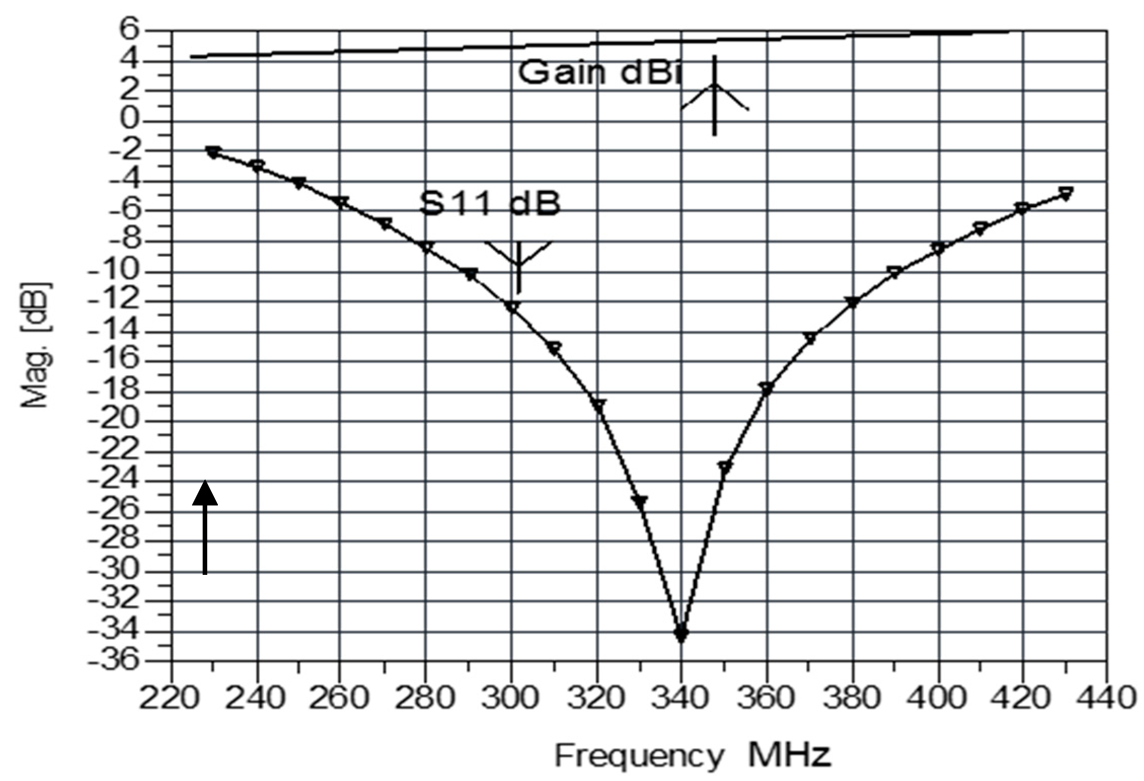
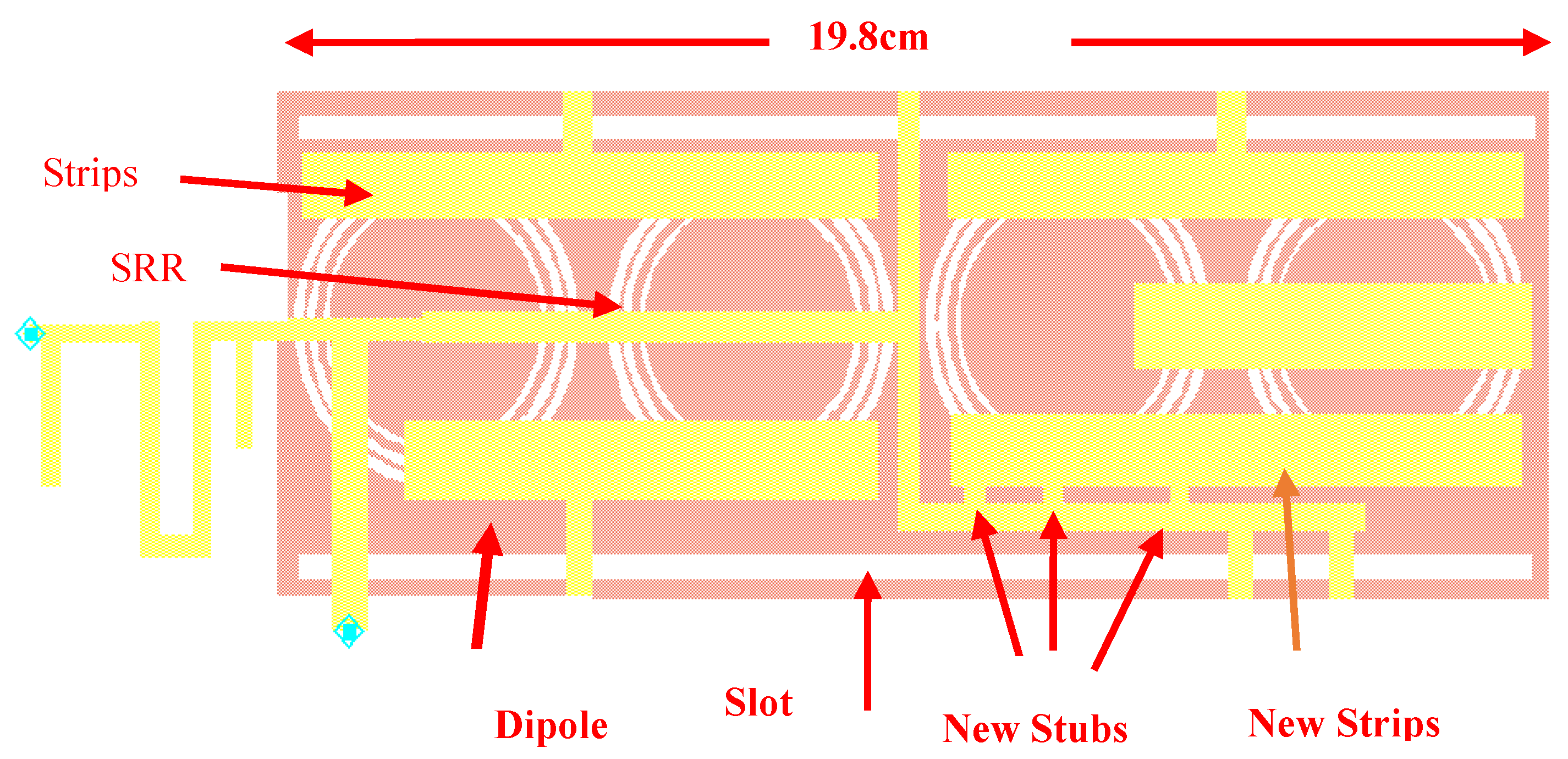
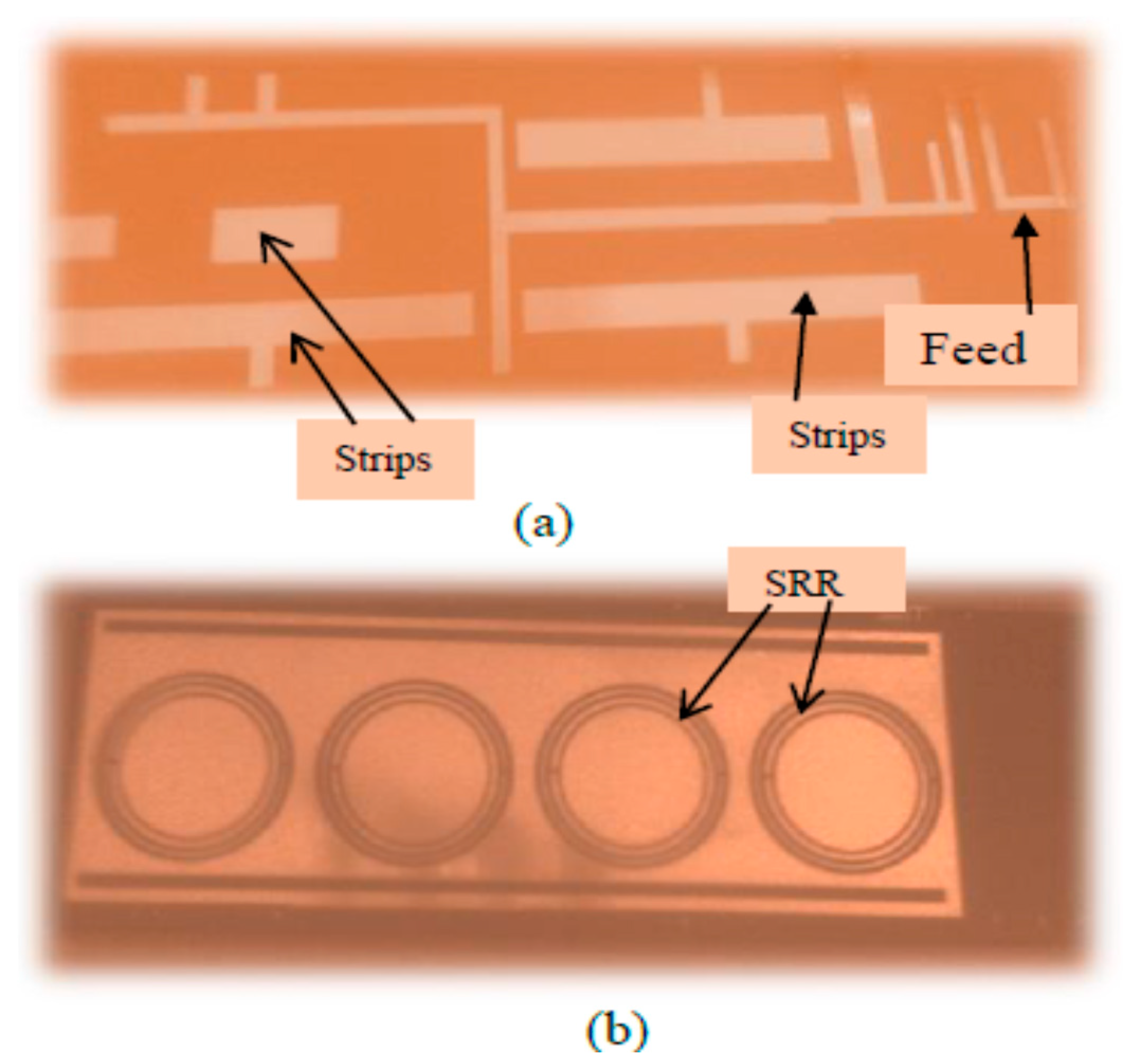
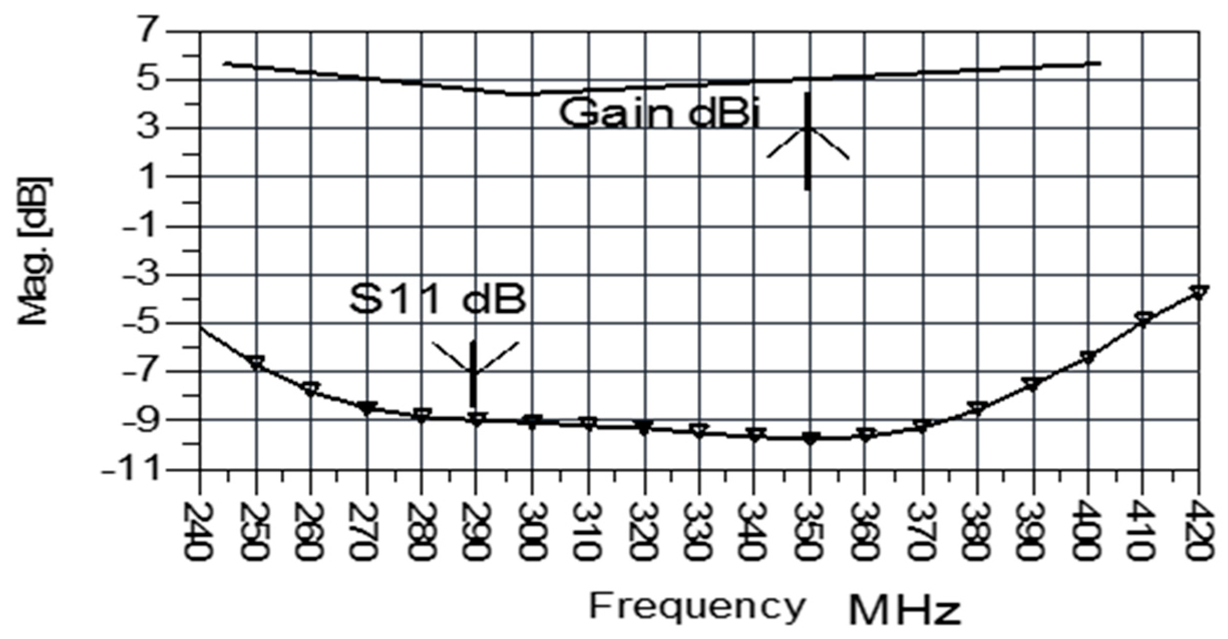
3. Wearable Antenna with SRR and Metallic Strips

A dual polarized antenna with SRR and metallic strips is presented in Figure 7. The flexible wearable antenna dimensions are 19.8 × 4 × 0.16 cm. The antenna was printed on RT Duroid 5880 with dielectric constant of 2.2. The dipole feed network and metallic strips are printed on the first layer. The radiating dipole with SRR is printed on the second layer. The thickness of each layer is 0.8 mm. The printed dipole with SRR is horizontal polarized. The slot antenna is vertical polarized. The dipole and the slot antenna create dual polarized antenna. The resonant frequency of the antenna with SRR is around 330 MHz. The resonant frequency of the antenna without SRR is 10% higher. The computed S11 and antenna gain are presented in Figure 8. The antenna bandwidth is around 46% for VSWR better than 3:1. The spherical computed radiation pattern is shown in Figure 9. Maximum radiation is in the z axis direction. Directivity and gain of the antenna with SRR are around 5.5 dBi as shown in Figure 10. The feed network of the antenna in Figure 7 was optimized to yield VSWR better than 2.5:1 in frequency range of 250 MHz to 420 MHz as shown in Figure 11. The SRR have an important role in the radiation characteristics of the antenna. The antenna with SRR and metallic strips was optimized and more stubs and metallic strips were added to yield wider bandwidth as shown in Figure 12. The reflection coefficient, S11, of the modified antenna with metallic strips and SRR is presented in Figure 13. The antenna bandwidth is around 65% for VSWR better than 3:1. The antenna beam width is around 100°.
Comparison between antennas with and without SRR is given in Table 2. The measured results agree with the computed results.

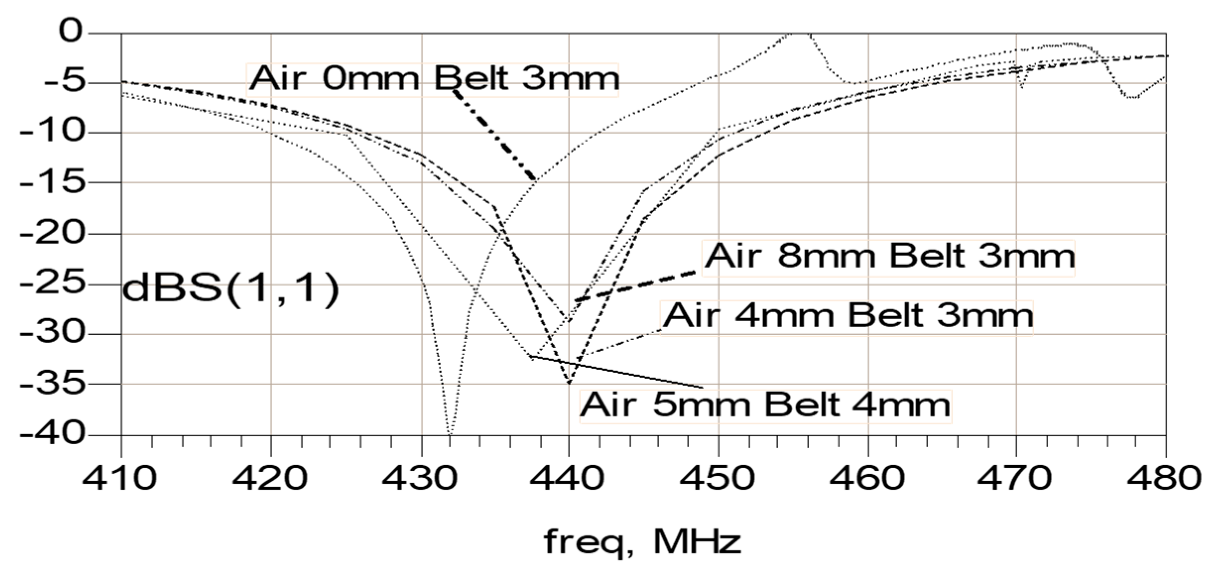
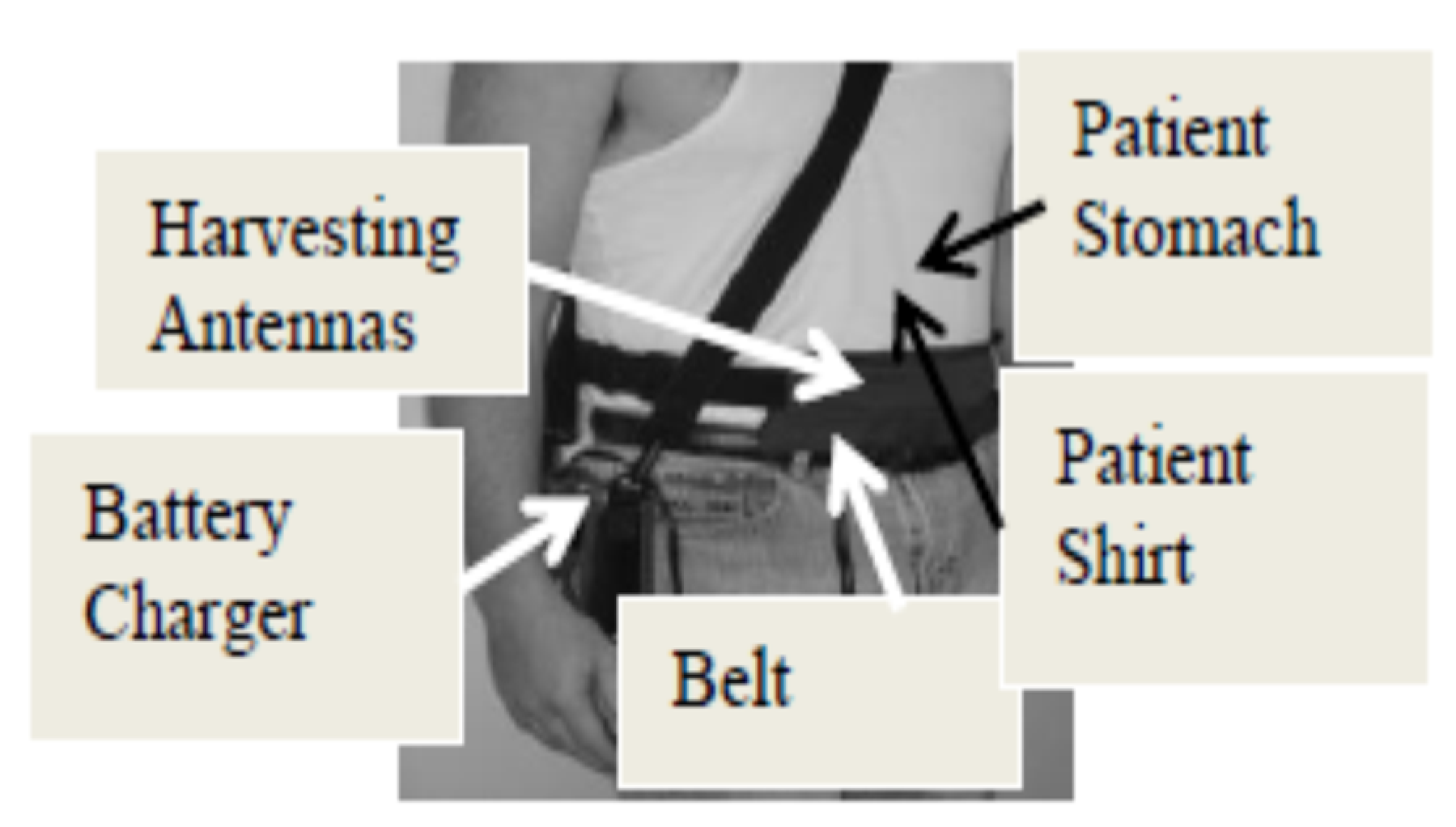
4. Metamaterial Antennas in Vicinity to the Patient Body

The metamaterial antennas S11 variation near the patient body were computed by using the structure presented in Figure 14a. Dielectric constant and conductivity of human body tissues are given in Table 3 [15]. The antenna location on the human body is considered by computing S11 for different dielectric constant and conductivity of the body tissues. The variation of the of body tissues dielectric constant from five at fat tissues to 43 at the stomach area, and to 63 at muscle tissues, shifts the antenna resonant frequency by 2% to 5%. The antenna was inserted inside a belt as shown in Figure 14b. The belt thickness was varied from 1 to 4 mm. The belt dielectric constant was varied from 2 to 4. The antennas impedance was computed and measured for air spacing of 0mm to 10mm, between the antennas and patient shirt.
The dielectric constant of the patient shirt was varied from 2.2 to 4.2. Figure 15 presents S11 results of the antennas with SRR and metallic strips. The antenna resonant frequency was shifted by 1% to 3%. Results presented in Figure 15 indicate that these antennas have VSWR better than 3:1 for 65% bandwidth. The radiation pattern of the antennas with metallic strips and SRR on human body is shown in Figure 16. S11 results for different belt thickness, shirt thickness and air spacing between the antennas and human body, for the antennas without SRR, are shown in Figure 17. One may conclude from results shown in Figure 17 that the antenna has S11 better than –9 dB for air spacing up to 10 mm between the antennas and the human body.
The antenna belt is attached to the patient’s body. The cable from each antenna is connected to the medical system.

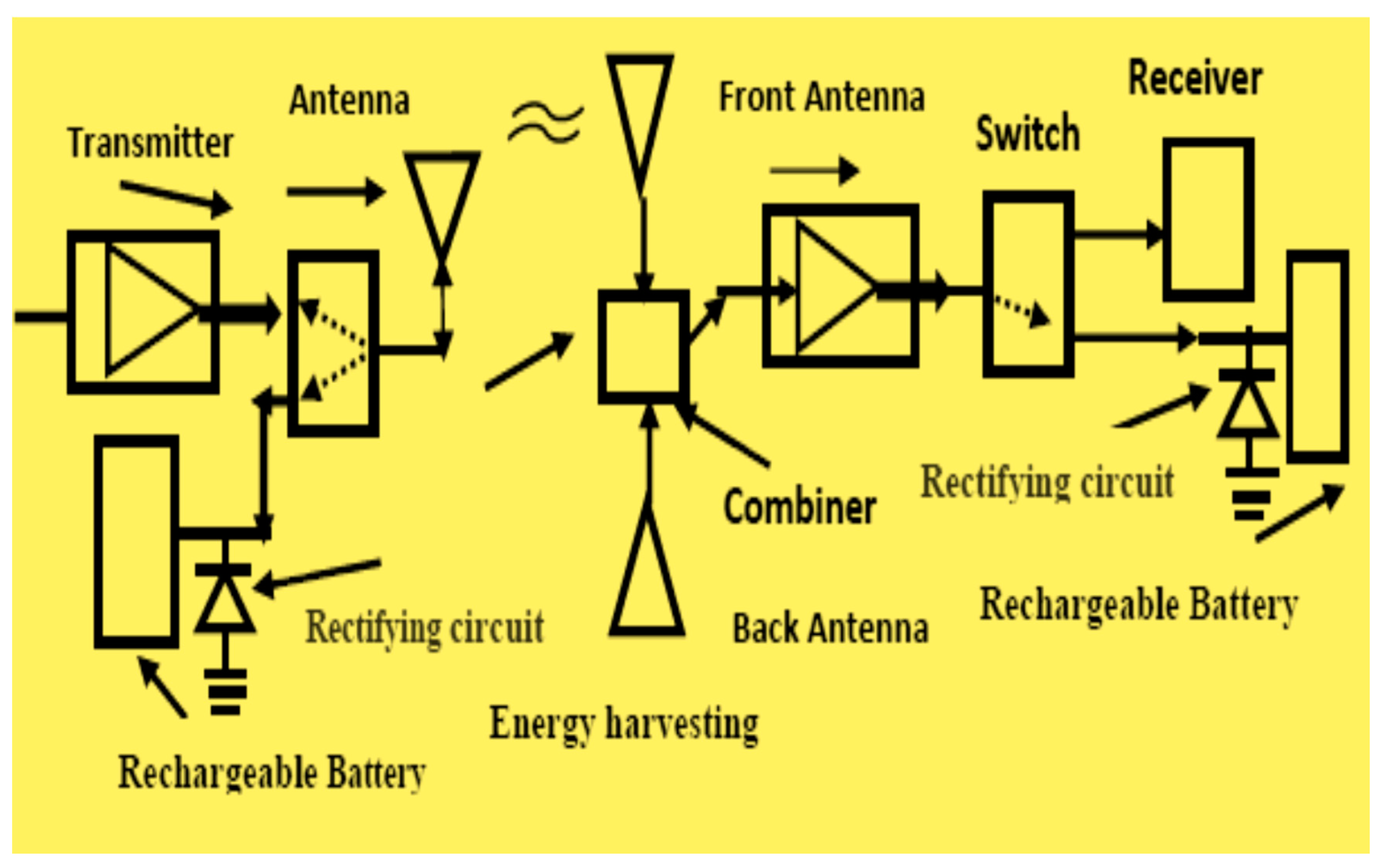
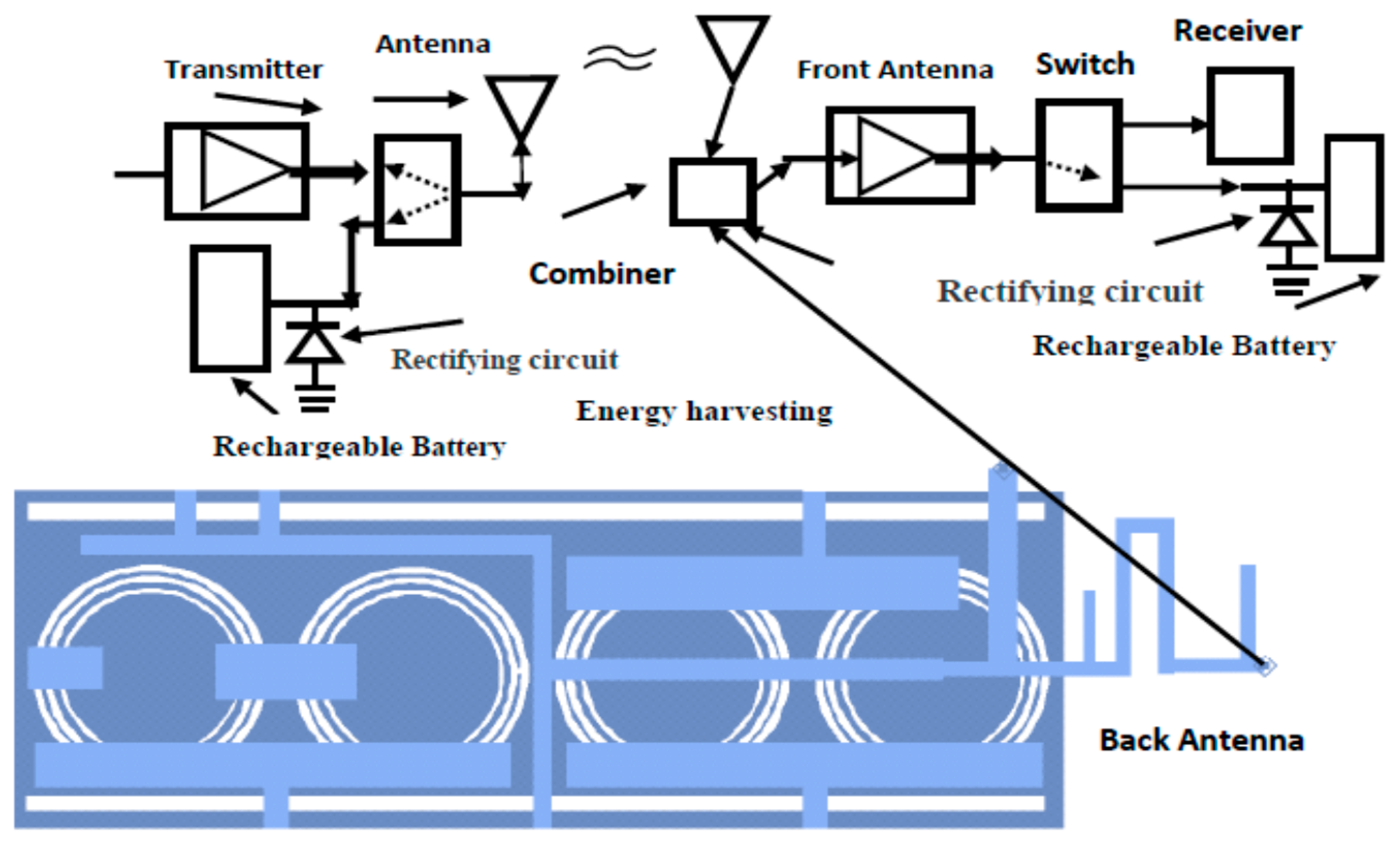
5. Wearable Harvesting System

The proposed meta materials antennas may be placed on the patient’s body as shown in Figure 18, which presents a medical monitoring health system with wearable antennas. The received signals are combined by a power combiner and transferred via a switch to the receiver and to the harvesting system, as presented in Figure 19. In several wearable systems the distance separating the transmitting and receiving antennas is in the near field zone. In the near-field area the antennas are magnetically coupled and only near field effects should be considered. The antennas electrical characteristics on human body may be measured by using a phantom that represents the electrical properties of the human body, as presented in [5].

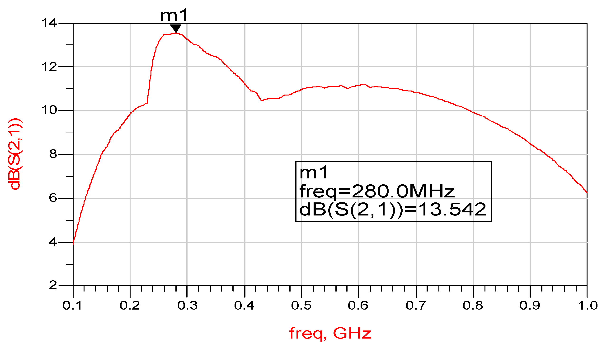
6. Active Metamaterial Receiving Wearable Antenna

Figure 19 presents a basic receiver block diagram. Receiving active antenna layout is shown in Figure 20. A matching network matches the antenna with SRR to the LNA. The LNA, is a high linearity gain block amplifier. At 1.9 GHz, the amplifier typically provides a 14dB gain. These antennas also function as transmitting antennas. The LNA output P1dB is 20 dBm. The LNA Noise Figure is 1.8dB. An output matching network matches the amplifier to the receiver. A DC bias network supplies the required voltages to the amplifiers. The active receiving meta materials antenna gain is 11+2 dB from 150 MHz to 900 MHz as shown in Figure 21.
A photo of the feed network and metallic strips is shown in Figure 22a. A photo of antenna with SRR is shown in Figure 22b. A comparison of electrical parameters of compact wearable antennas for medical, 5G and IOT systems is listed in Table 4. Printed dipole with and without SRR were presented in [1]. Results listed in Table 4 show that the gain of printed dipole with SRR is 3 dB higher than the printed dipole without SRR. Wideband passive and active slot antennas were presented in [1]. An Enhancement PHEMT, Pseudo morphic High Electron Mobility Transistor, LNA was connected to the antenna, as shown in Figure 22. At 2 GHz, the amplifier has an 18dB gain. The LNA output P1dB is 19 dBm. The LNA Noise Figure is 0.5dB. The active receiving metamaterial antenna gain is 12 + 2 dB from 250 MHz to 950 MHz, as shown in Figure 23. The active receiving meta materials antenna Noise Figure is 0.4 + 0.2 dB from 250 MHz to 950MHz. The DC bias voltage of the LNA amplifiers is 3 V.
The harvesting energy system operates as a dual mode energy harvesting system that can charge the battery when the switch is connected to the harvesting system. At standby mode of the communication system, the switch disconnects the receiver and connects the harvesting system to the active antenna. The harvesting system efficiency increases as function of the RF input power to the harvesting system as listed in Table 5. The amplifier amplifies the input power at the input of the energy harvesting system and improves the efficiency of the harvesting system. Results listed in Table 5 are also presented by companies that manufacture commercial RF energy harvesting systems.

7. Conclusions

Compact flexible antennas with high efficiency for medical and IOT systems were developed by employing meta material structures. Wideband, small, wearable, passive and active energy harvesting systems and antennas in frequencies ranging from 0.1 GHz to 1 GHz are presented in this paper. The antennas are placed in a belt and may be used to measure the patient’s medical health. The wearable antennas are compact and can be attached to the body. The antennas also allow the patient’s easy movement (running, jumping and working). The electromagnetic energy is converted to DC energy that may be employed to charge batteries, wearable medical devices and commercial Body Area Networks (BANs). A new class of wideband printed meta materials antennas with high efficiency is presented. The bandwidth of the antenna with SRR and metallic strips is around 65% for VSWR better than 3:1. Optimization of the antenna feed network, number of the coupling stubs, SRR configuration and the location of the metallic strips may be used to tune the antenna resonant frequency, radiation characteristics and the antenna bandwidth. The length of the antennas without SRR is 10% higher than the antennas with SRR. The resonant frequency of the antennas without SRR is 5–10% higher than the antennas with SRR. The gain and directivity of the wearable antennas with SRR is up to 3 dB higher than the antennas without SRR. The measured results agree with computed results.
Usually harvested power from RF transmitting links at crowded places, malls and stadiums, is around 1 mW/cm2. The harvesting energy system operates as a Dual Mode Energy harvesting system that can charge the battery when the switch is connected to the harvesting system in standby mode. Usually the switch is connected to the receiving system. The receiving system employs an LNA to improve the system SNR. The LNA DC bias voltages are supplied by the receiving system DC unit. The harvesting system efficiency increases as function of the RF input power to the harvesting system. These results are also presented by companies that manufacture commercial RF energy harvesting systems.
Harvesting system efficiency and dynamic range may be improved by using active antennas. All antennas presented in this paper can function as passive and active antennas.

Funding

This research received no external funding.

Conflicts of Interest

The author declares no conflict of interest.

References

  1. Sabban, A. Novel Wearable Antennas for Communication and Medical Systems; Taylor & Francis Group: London, UK, October 2017. [Google Scholar]
  2. Sabban, A. Wideband RF Technologies and Antenna in Microwave Frequencies; Wiley Sons: Hoboken, NJ, USA, July 2016. [Google Scholar]
  3. Sabban, A. Low Visibility Antennas for Communication System; Taylor & Francis Group: Boca Raton, FL, USA, 2015. [Google Scholar]
  4. Sabban, A. Microstrip Antenna Arrays. In Microstrip Antennas; InTechOpen: London, UK, 2011; pp. 361–384. ISBN 978-953-307-247-0. [Google Scholar]
  5. Sabban, A. New wideband printed antennas for medical applications. IEEE J. Trans. Antennas Propag. 2013, 61, 84–91. [Google Scholar] [CrossRef]
  6. Pendry, J.B.; Holden, A.J.; Stewart, W.J.; Youngs, I. Extremely low frequency plasmons in metallic mesostructures. Phys. Rev. Lett. 1996, 76, 4773–4776. [Google Scholar] [CrossRef] [PubMed]
  7. Pendry, J.B.; Holden, A.J.; Robbins, D.J.; Stewart, W.J. Magnetism from conductors and enhanced nonlinear phenomena. IEEE Trans. MTT 1999, 47, 2075–2084. [Google Scholar] [CrossRef]
  8. Marque’s, R.; Mesa, F.; Martel, J.; Medina, F. Comparative analysis of edge and broadside coupled split ring resonators for metamaterial design. Theory and experiment. IEEE Trans. Antennas Propag. 2003, 51, 2572–2581. [Google Scholar] [CrossRef]
  9. Marque’s, R.; Baena, J.D.; Martel, J.; Medina, F.; Falcone, F.; Sorolla, M.; Martín, F. Novel small resonant waveguides electromagnetic particles for metamaterial and filter design. Phys. Rev. Lett. 2003, 89, 439–442. [Google Scholar]
  10. Marque’s, R.; Martel, J.; Mesa, F.; Medina, F. Left-handed-media simulation and transmission of EM waves in sub wavelength split-ring-resonator loaded metallic waveguides. Phys. Rev. Lett. 2002, 89, 183901. [Google Scholar] [CrossRef] [PubMed]
  11. Rajab, K.-Z.; Mittra, R.; Lanagant, M.T. Size reduction of microstrip antennas using metamaterials. In Proceedings of the 2005 IEEE APS Symposium, Washington, DC, USA, 3–8 July 2005. [Google Scholar]
  12. Jiang, Z.; Eleftheriades, G.V. A Compact Transmission line metamaterial antenna with Extended Bandwidth. IEEE Antennas Wirel. Propag. Lett. 2009, 8, 295–298. [Google Scholar] [CrossRef]
  13. Baena, J.N.; Marque’s, R.; Martel, J.; Medina, F. Experimental results On Metamaterial simulation using SRR-loaded waveguides. In Proceedings of the IEEE-AP/S International Symposium on Antennas and Propagation, Columbus, OH, USA, 22–27 June 2003; pp. 106–109. [Google Scholar]
  14. Marque’s, R.; Martel, J.; Mesa, F.; Medina, F. A new 2-D isotropic left-handed Metamaterial design: Theory and experiment, Microwave Opt. Tech. Lett. 2002, 35, 405–408. [Google Scholar]
  15. Shelby, R.A.; Smith, D.R.; Nemat-Nasser, S.C.; Schultz, S. Microwave transmission through a two-dimensional, left-handed meta- material. Appl. Phys. Lett. 2001, 78, 489–491. [Google Scholar] [CrossRef]
  16. Chirwa, L.C.; Hammond, P.A.; Roy, S.; Cumming, D.R.S. Electromagnetic Radiation from Ingested Sources in the Human Intestine between 150 MHz and 1.2 GHz. IEEE Trans. Biomed. Eng. 2003, 50, 484–492. [Google Scholar] [CrossRef] [PubMed]
  17. Werber, D.; Schwentner, A.; Biebl, E.M. Investigation of RF transmission properties of human tissues. Adv. Radio Sci. 2006, 4, 357–360. [Google Scholar] [CrossRef]
  18. Gupta, B.; Sankaralingam, S.; Dhar, S. Development of wearable and implantable antennas in the last decade. In Proceedings of the 2010 Mediterranean Microwave Symposium (MMS), Guzelyurt, Cyprus, 25–27 August 2010; pp. 251–267. [Google Scholar]
  19. Thalmann, T.; Popovic, Z.; Notaros, B.M.; Mosig, J.R. Investigation and design of a multi-band wearable antenna. In Proceedings of the 3rd European Conference on Antennas and Propagation, Berlin, Germany, 23–27 March 2009; pp. 462–465. [Google Scholar]
  20. Salonen, P.; Rahmat-Samii, Y.; Kivikoski, M. Wearable antennas in the vicinity of human body. IEEE Antennas Propag. Symp. 2004, 1, 467–470. [Google Scholar]
  21. Sabban, A. Wideband printed antennas for medical applications. In Proceedings of the APMC Conference, Singapore, 7–10 December 2009. [Google Scholar]
  22. Alomainy, A.; Sani, A.; Rahman, A.; Santas, J.-G.; Hao, Y. Transient characteristics of Wearable antennas and Radio propagation channels for ultra- wideband body wireless communication. IEEE Trans. Antennas Propag. 2009, 57, 875–884. [Google Scholar] [CrossRef]
  23. Klemm, M.; Troester, G. Textile UWB antenna for wireless body area networks. IEEE Trans. Antennas Propag. 2006, 54, 3192–3197. [Google Scholar] [CrossRef]
  24. Izdebski, P.M.; Rajagoplan, H.; Rahmat-Samii, Y. Conformal ingestible capsule antenna: A novel chandelier meandered design. IEEE Trans. Antennas Propag. 2009, 57, 900–909. [Google Scholar] [CrossRef]
  25. Sabban, A. Wideband tunable printed antennas for medical applications. In Proceedings of the IEEE Antenna and Propagation Symposium, Chicago, IL, USA, 8–14 July 2012. [Google Scholar]
  26. James, J.R.; Hall, P.S.; Wood, C. Microstrip Antenna Theory and Design; IET: London, UK, 1981. [Google Scholar]
  27. Sabban, A. A new wideband stacked microstrip antenna. In Proceedings of the IEEE Antenna and Propagation Symposium, Houston, TX, USA, 23–26 May 1983. [Google Scholar]
  28. Paradiso, J.A.; Starner, T. Energy scavenging for mobile and wireless electronics. IEEE Pervasive Comput. 2005, 4, 18–27. [Google Scholar] [CrossRef]
  29. Valenta, C.R.; Durgin, G.D. Harvesting wireless power: Survey of energy-harvester conversion efficiency in far-field, wireless power transfer systems. IEEE Microw. Mag. 2014, 15, 108–120. [Google Scholar]
  30. Nintanavongsa, P.; Muncuk, U.; Lewis, D.R.; Chowdhury, K.R. Design optimization and implementation for RF energy harvesting circuits. IEEE J. Emerg. Sel. Top. Circuits Syst. 2012, 1, 24–33. [Google Scholar] [CrossRef]
Figure 1. Dual mode energy harvesting concept.
Electronics 08 01340 g001
Figure 2. Presentation of a diode half wave rectifier.
Electronics 08 01340 g002
Figure 3. Improved half wave diode rectifier.
Electronics 08 01340 g003
Figure 4. Basic full-wave bridge diode rectifier.
Electronics 08 01340 g004
Figure 5. Full wave bridge diode rectifier.
Electronics 08 01340 g005
Figure 6. Medical wearable harvesting system.
Electronics 08 01340 g006
Figure 7. Antenna with metallic strips and Split Ring Resonators (SRR).
Electronics 08 01340 g007
Figure 8. Gain and S11 of the antenna with metallic strips and SRR.
Electronics 08 01340 g008
Figure 9. Spherical radiation pattern for antenna with metallic strips and SRR.
Electronics 08 01340 g009
Figure 10. Gain of the antenna with strips and SRR.
Electronics 08 01340 g010
Figure 11. S11 and gain for antenna with metallic strips
Electronics 08 01340 g011
Figure 12. Wideband improved and optimized antenna with metallic strips and SRR.
Electronics 08 01340 g012
Figure 13. S11 for antenna with metallic strips.
Electronics 08 01340 g013
Figure 14. (a) Antenna environment and (b) wearable system on a patient.
Electronics 08 01340 g014aElectronics 08 01340 g014b
Figure 15. Antennas with SRR S11 results on a patient.
Electronics 08 01340 g015
Figure 16. Radiation pattern for antenna with SRR shown in Figure 13 on the human body.
Electronics 08 01340 g016
Figure 17. S11 results for different locations relative to the patient’s body for the antenna without SRR.
Electronics 08 01340 g017
Figure 18. Medical monitoring health system with wearable antennas.
Electronics 08 01340 g018
Figure 19. Wearable harvesting system with front and back antennas.
Electronics 08 01340 g019
Figure 20. Wearable dual mode harvesting system with front and back antennas.
Electronics 08 01340 g020
Figure 21. Active receiving antenna gain.
Electronics 08 01340 g021
Figure 22. Photo of antenna with SRR and metallic strips (a). Feed network and metallic strips (b). Antenna with SRR.
Electronics 08 01340 g022
Figure 23. Active receiving antenna gain with PHEMT LNA.
Electronics 08 01340 g023
Table 1. Energy sources used in harvesting systems [28,29,30].
Energy SourceTypeEfficiencyHarvested Energy
LightFree space11~25%100 mW/cm2
Heat energyMankind
Industrial
~0.12%
~3.2%
60 µW/cm2
1–10 mW/cm2
Vibration energy~Hz–Mankind
~kHz–machines
20~52%~5 µW/cm3
~810 µW/cm3
RF energy0.9–2.7GHz—Indoor~50%0.1 µW/cm2
RF energy0.9–2.7GHz—At malls~50%1 mW/cm2
Table 2. Comparison between antennas with SRR.
AntennaFrequency. (MHz)VSWR %Gain (dBi)Length
(cm)
With SRR350105.519.8
Without SRR400102.521
SRR and Strips300505.519.8
Table 3. Electrical properties of body tissues [16,17].
TissueProperty435 MHz605 MHz995 MHz
Human fatσ
ε
0.045
5.00
0.05
5
0.06
4.50
Human stomachσ
ε
0.67
42.9
0.75
41.40
0.97
39.05
Patient Colonσ
ε
1.00
63.6
1.05
61.9
1.30
60.00
Skinσ
ε
0.57
41.6
0.6
40.45
0.63
40.25
Human lungσ
ε
0.27
38.4
0.27
38.4
0.27
38.4
Human kidneyσ
ε
0.90
117.45
0.90
117.45
0.90
117.45
Table 4. Comparison of electrical characteristics of wearable antennas [1,2].
AntennaBandwidth %VSWRGain dBi
Printed dipole5–102:12–3
Dipole with SRR8–122:15–7
SRR and strips502.5:15–7.5
Loop5–104:10
Patch1–32:12–3
Stacked Patch10–152:14–5
Slot502:13
T shape slot602:13
Active slot403:112–20
Active T slot503:112–20
Active with SRR502.5:110–16
Table 5. Harvester efficiency as function of input power.
Input Power dBmEfficiency %Remarks
−510Low Efficiency
−330Low Efficiency
050Good Efficiency
355Good Efficiency
550Good Efficiency
755Good Efficiency
1060Best Efficiency

