Article

Arm-ECG Wireless Sensor System for Wearable Long-Term Surveillance of Heart Arrhythmias

1
Image Processing Centre, Universidad de Carabobo, Valencia, C.P. 2001, Venezuela
2
Cardiovascular Research Unit, Craigavon Area Hospital, SHSCT, BT63 5QQ Portadown, UK
3
School of Engineering, Ulster University, BT37 0QB Newtownabbey, UK
*
Author to whom correspondence should be addressed.
Electronics 2019, 8(11), 1300; https://doi.org/10.3390/electronics8111300
Submission received: 10 October 2019 / Revised: 4 November 2019 / Accepted: 6 November 2019 / Published: 7 November 2019
(This article belongs to the Section Bioelectronics)

Abstract

:
This article presents the devising, development, prototyping and assessment of a wearable arm-ECG sensor system (WAMECG1) for long-term non-invasive heart rhythm monitoring, and functionalities for acquiring, storing, visualizing and transmitting high-quality far-field electrocardiographic signals. The system integrates the main building blocks present in a typical ECG monitoring device such as the skin surface electrodes, front-end amplifiers, analog and digital signal conditioning filters, flash memory and wireless communication capability. These are integrated into a comfortable, easy to wear, and ergonomically designed arm-band ECG sensor system which can acquire a bipolar ECG signal from the upper arm of the user over a period of 72 h. The small-amplitude bipolar arm-ECG signal is sensed by a reusable, long-lasting, Ag–AgCl based dry electrode pair, then digitized using a programmable sampling rate in the range of 125 to 500 Hz and transmitted via Wi-Fi. The prototype comparative performance assessment results showed a cross-correlation value of 99.7% and an error of less than 0.75% when compared to a reference high-resolution medical-grade ECG system. Also, the quality of the recorded far-field bipolar arm-ECG signal was validated in a pilot trial with volunteer subjects from within the research team, by wearing the prototype device while: (a) resting in a chair; and (b) doing minor physical activities. The R-peak detection average sensibilities were 99.66% and 94.64%, while the positive predictive values achieved 99.1% and 92.68%, respectively. Without using any additional algorithm for signal enhancement, the average signal-to-noise ratio (SNR) values were 21.71 and 18.25 for physical activity conditions (a) and (b) respectively. Therefore, the performance assessment results suggest that the wearable arm-band prototype device is a suitable, self-contained, unobtrusive platform for comfortable cardiac electrical activity and heart rhythm logging and monitoring.

1. Introduction

Despite the overall decrease in cardiovascular mortality in recent decades, sudden cardiac death, usually caused by lethal arrhythmias, accounts for 50% of heart disease-related deaths and occurs among patients never diagnosed or previously classified as at low cardiovascular risk [1]. Different paroxysmal arrhythmias only manifest sporadic symptoms requiring long-term cardiac monitoring for correct diagnosis [2]. In such cases, implantable loop recorders (ILRs) are currently becoming more common and are considered as an important tool by clinicians; however, their use requires costly surgical procedures and carries infection risks [3]. Holter monitors offer high-quality ECG signals for medical diagnosis, but they are typically limited to 24–48 h of continuous use since they require wires that interfere with user’s daily activities and skin-adhesive-based electrodes, which may produce patient discomfort after a few days [4] and the adhesive regularly degrades causing electrodes to detach as a result of sweating. Cost-effective, non-invasive, long-term ECG monitoring alternatives for early detection of arrhythmias can have a positive impact on the effectiveness of heart disease treatment, therefore reducing mortality and improving patient’s prognosis, particularly in an ageing population [5].
In recent years, technological advances in electronics, wireless communications, sensor materials and physiological data-processing tools have made possible ubiquitous computing available for healthcare applications [6]. As a result, a variety of experimental wearable smart devices have been developed for ECG monitoring; they include T-shirts or vests [7,8], belts [9,10], adhesive patches [11,12] and armbands [13]. In addition, there are commercially available systems in the form of portable Holter monitors (e.g., NH-301 (Norav Medical GmhH, Wiesbaden, Germany)), adhesive patches (e.g., Zio (iRhythm San Francisco, CA, USA)) and smartwatches (e.g., Apple Watch 5 (Apple Inc., Cupertino, CA, USA)), targeting similar applications. Still, every technology has its advantages, limitations and drawbacks. Portable Holter devices and ECG patches are currently accepted as medical-grade devices; however, as stated above they use gelled electrodes and adhesive materials that produce skin irritation and are susceptible to detach due to sweat or moisture. ECG monitoring systems based on textile electrodes and ECG T-shirts, in particular, have been studied over the last decade [7]. They represent an interesting approach to unobtrusive cardiac activity measurement. Nevertheless, they require a stretch fit adapted to the user’s body for tribological noise reduction and they are not designed to be worn for long periods (>24 h). Other approaches, such as smartwatches or smartphone-based ECG recorders, interfere with users’ daily routines since they require touching specific metallic pads on the device for ECG measurement, e.g., KardiaMobile (AliveCor Inc., Mountain View, CA, USA). Therefore, they are only suitable for intermittent patient monitoring. Although ECG armband devices have been less explored than other options, they offer substantial advantages regarding user comfort and adaptability being, therefore, a convenient option for long-term continuous usage.
Lynn et al. reported a feasibility study which provides sufficient evidence for the development of an ECG monitor worn at the left arm in [3], including the viability of using contactless dry electrode systems (EPIC™ Sensor (Plessey Semiconductors, Plymouth, UK)) [14]. Escalona et al. [5] reported preliminary studies which indicated the best possible electrode locations for ECG signal recordings along the left arm. Their results suggested different locations for accurate ECG signal reconstruction using far-field potentials, especially across the upper left arm. A posterior analysis using advanced denoising techniques was applied to 34 clinical cases showing three primary locations for this purpose [4]. More recently, Vizcaya et al. [15] used an arm-ECG database gathered from 153 subjects to develop a method based on artificial intelligence for estimation of standard ECG Lead I using a single bipolar upper-arm ECG signal.
This paper presents the devising and development of a novel unobtrusive upper-arm wearable prototype system device for ECG monitoring and recording on the upper-left arm. The research team continue their 10-year contribution investigating the possibilities of extracting meaningful ECG information using far-field potentials in long-term cardiac rhythm monitoring. The raw bipolar electrograms, recorded using the proposed arm wearable band with reusable dry electrodes, are analyzed and compared to data acquired using wet gel electrodes in our previous studies.

2. Materials and Methods

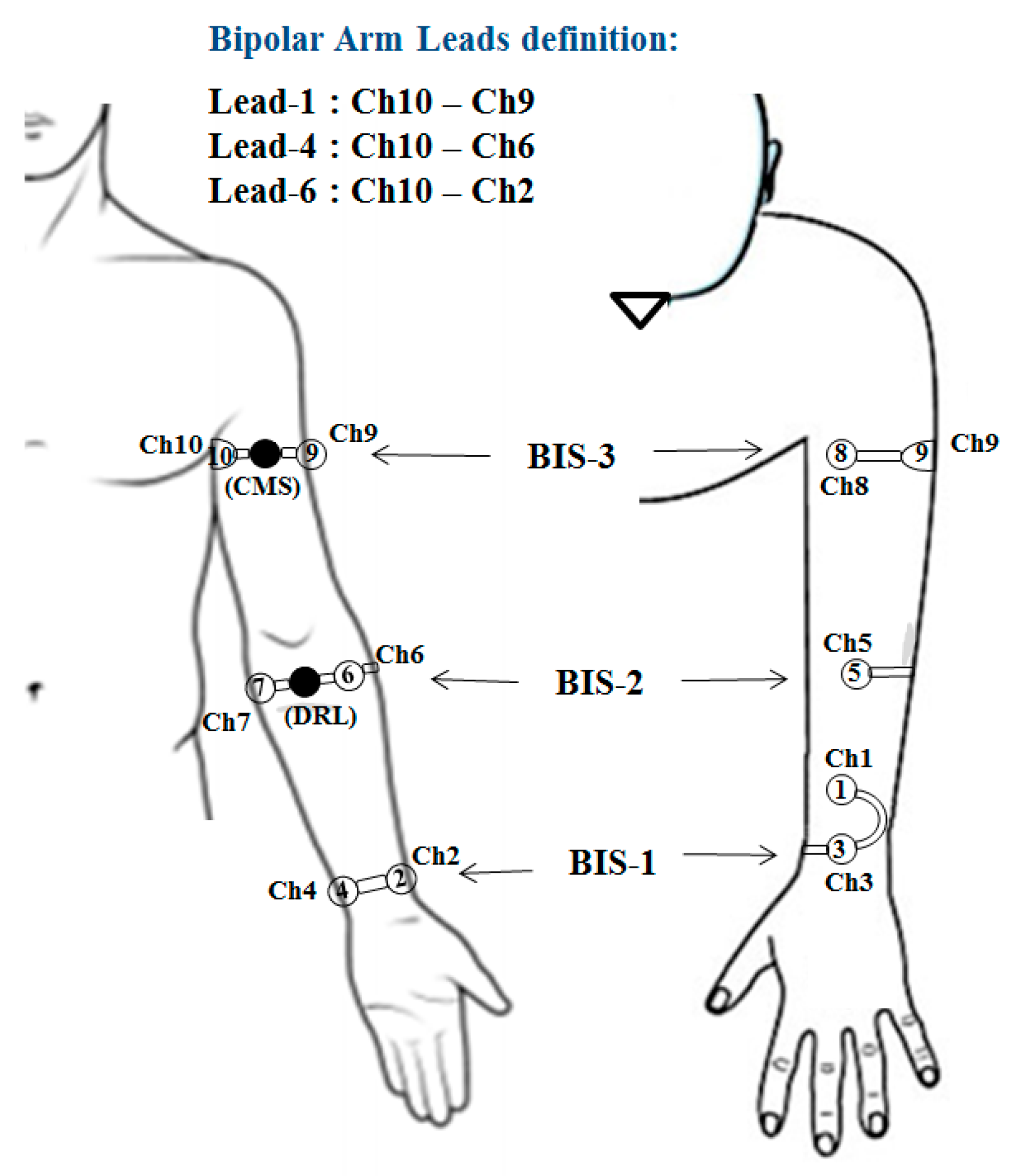
2.1. Bipolar Arm-ECG Signals

Previous studies have reported the feasibility and potential advantages of an arm-worn device for non-invasive cardiac rhythm monitoring, using dry electrodes located in a comfort zone for wearable devices recommended by Gemperle et al. [16]. The reported best amplitude range of recorded cardiac electrical signals, or ECGs, ranged from 12.67 to 225.5 uV (p-p), with signal-to-noise ratio (NSR) values from 1.27 to 197.5 [3]. Although the bipolar ECG signals from the upper arm were shown to have the best signal strength characteristics for ECG monitoring purposes, they are still of low amplitude and are prone to power line and electromyographic (EMG) interference, besides the additional noise artefacts resulting from electrode movement. Nevertheless, effective denoising techniques for arm-ECG are currently available for the treatment of far-field arm-ECG signals. In previous studies [4], bipolar lead electrodes have been positioned (transversally and axially oriented) on different anatomical locations along the left upper-arm. The study has suggested a transversally-oriented bipolar lead on the upper arm (see Lead-1 definition in Figure 1) as one of the most suitable localizations for ECG signal recovery, and that other locations (Lead-4 and Lead-6) can also provide meaningful ECG information. However, they are not useful for constructing an arm-band wearable device, which can secure the dry ECG electrode system against the skin surface without the need of any adhesive substance.

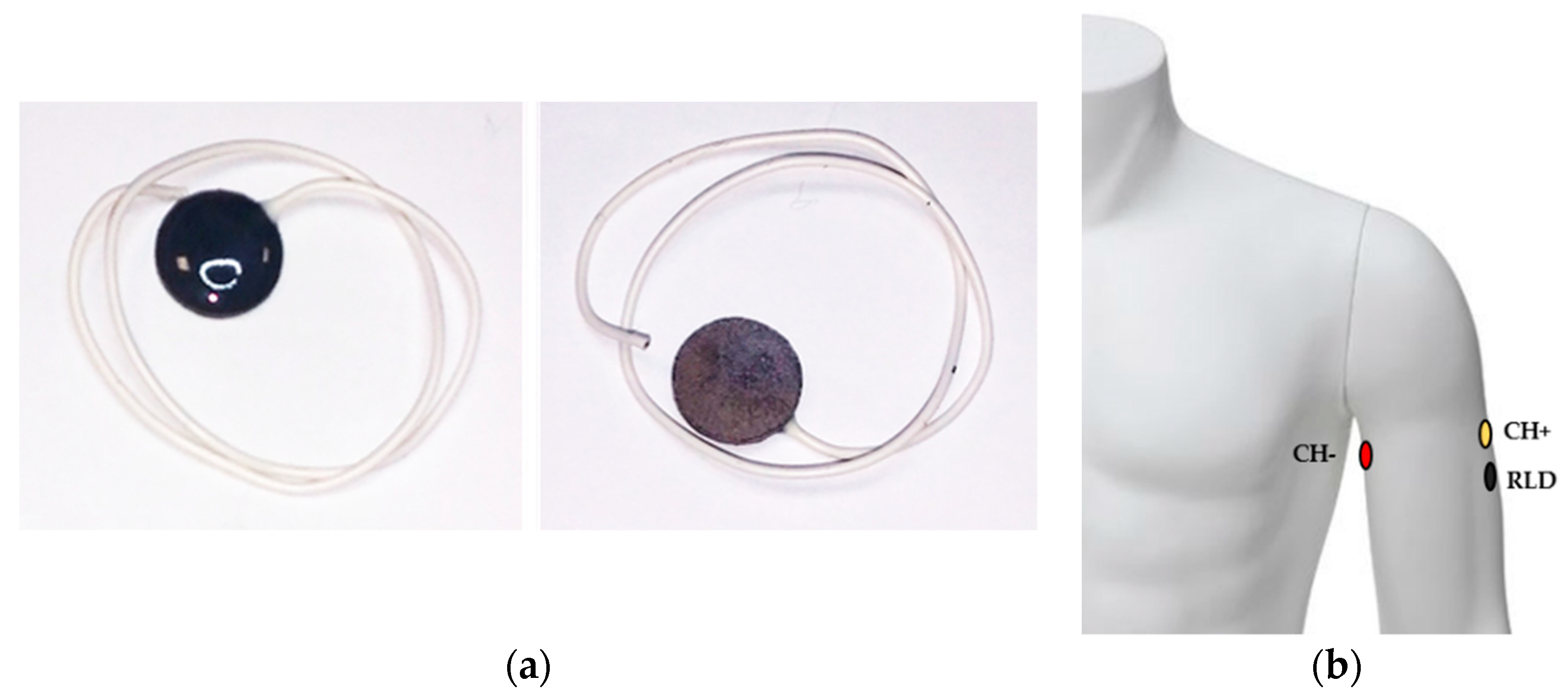
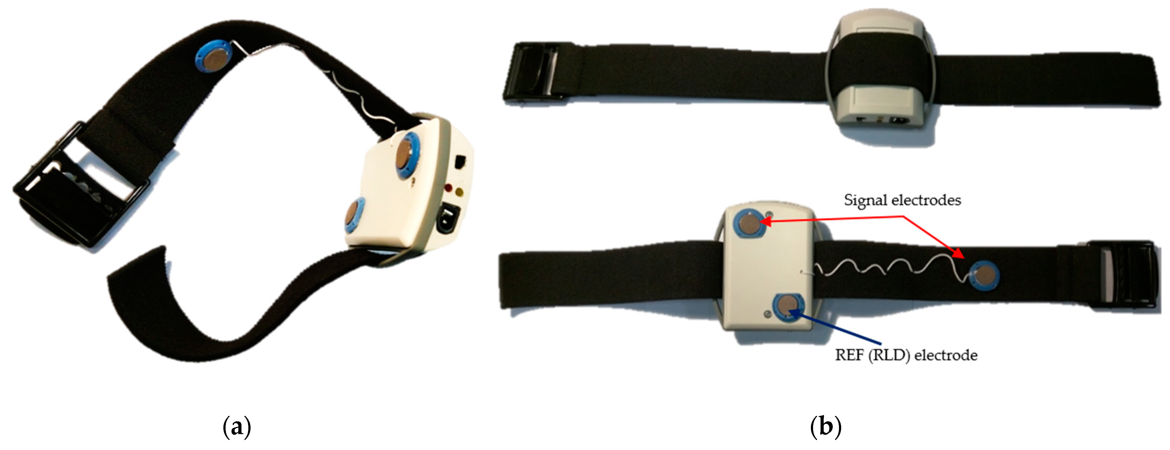
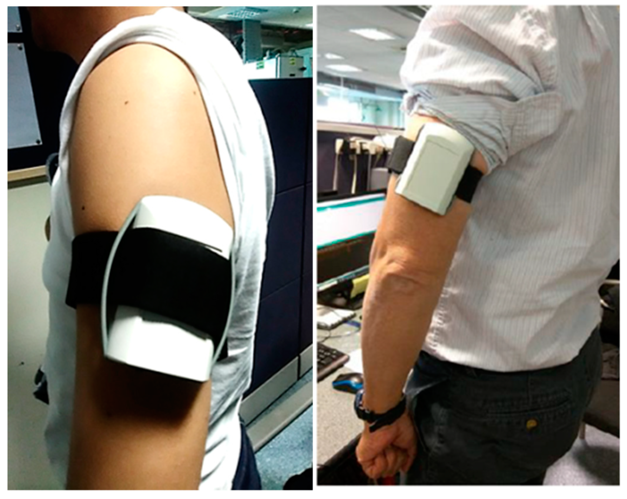
2.1.1. Dry ECG Electrode System

The possible materials used for dry-electrode systems in wearable long-term ECG devices is still an open issue. Several studies have proposed textile and flexible electrodes [7,17], non-contact capacitive electrodes [13,14,18,19] and traditional bio-compatible metallic disc electrodes [20]. In particular, the works of Chi et al. [8] and Meziane et al. [21] present extensive literature reviews on dry-electrode technologies for ECG recording applications.
ECG acquisition systems rely on the stability of the skin–electrode interface impedance for proper operation. In a previous study, Bosnjak et al. [22] experimentally characterized this parameter with various dry-electrode materials for wearable cardiac rhythm monitoring systems. Silver–silver chloride (Ag–AgCl) dry electrodes showed the second-best results in the frequency range from 0.05 to 150 Hz. Also, the study compared the ECG signal waveforms recorded with standard pre-gelled Ag–AgCl electrodes to the signal quality obtained using a range of dry-electrode materials. The use of dry (non-gelled) Ag–AgCl electrodes showed better results in comparison to other materials, hence supporting the decision of using them in the arm-ECG recording device [5].
More specifically, we decided to use 10-mm sintered silver–silver chloride electrode disks (Figure 2a), which proved to be more electrically stable for long-term operation than Ag/AgCl electrodes manufactured with a galvanization process [23,24], offering advantages of relatively low impedance, being re-usable (in one subject) and long-lasting. They also have a non-polarizable behavior and higher mechanical stability than regular silver–silver chloride electrodes [25]. Furthermore, sintered Ag–AgCl electrodes are increasingly being used for measurements of very low amplitude biopotential signals [25]. Nevertheless, due to the rigid nature of the electrode–skin interface in dry electrodes, they are more prone to present motion artefact and ECG baseline instability problems. To mitigate the latter issue, it is helpful to restrict the bandwidth of the ECG signal monitoring to between 0.5 and 40 Hz at the front-end stage as described in the following section.
The position of the electrodes was selected considering the results we reported from our previous works [4,5]. According to these studies, the most convenient anatomical location for a bipolar arm-ECG recording lead is using a transversally disposed electrode pair at the upper arm, as shown in Figure 2b. In this way, the arm-ECG signal can be recorded with sufficient amplitude and tolerable noise levels for reliable QRS complex detection and waveform features extraction, as well as heart rate and possible standard ECG Lead I estimation and reconstruction from the bipolar arm-ECG lead [15].

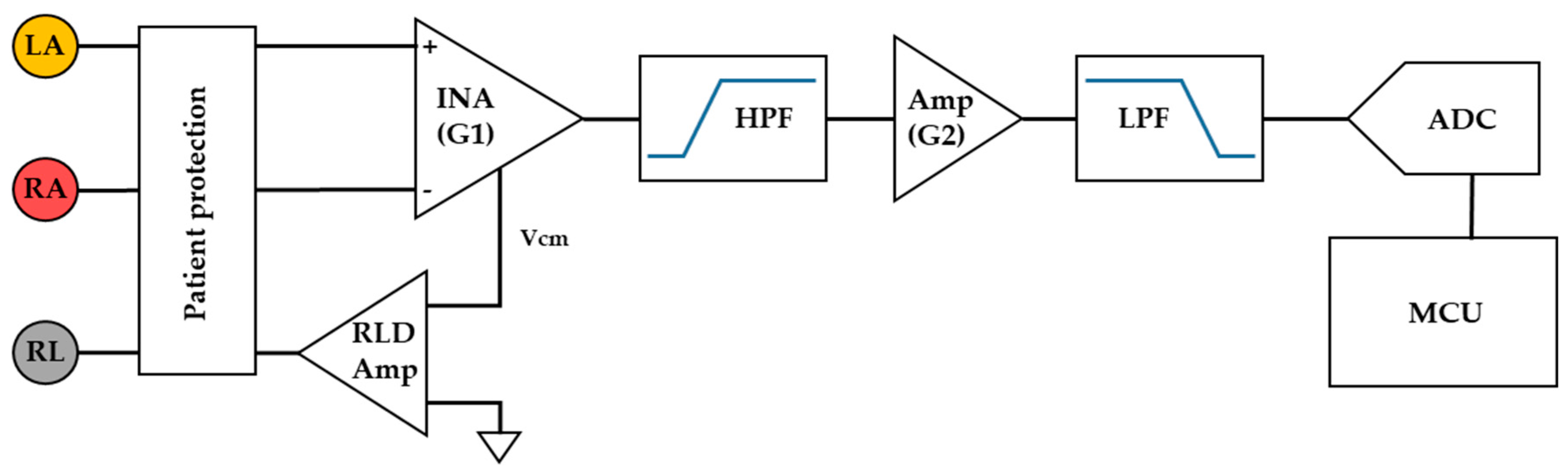
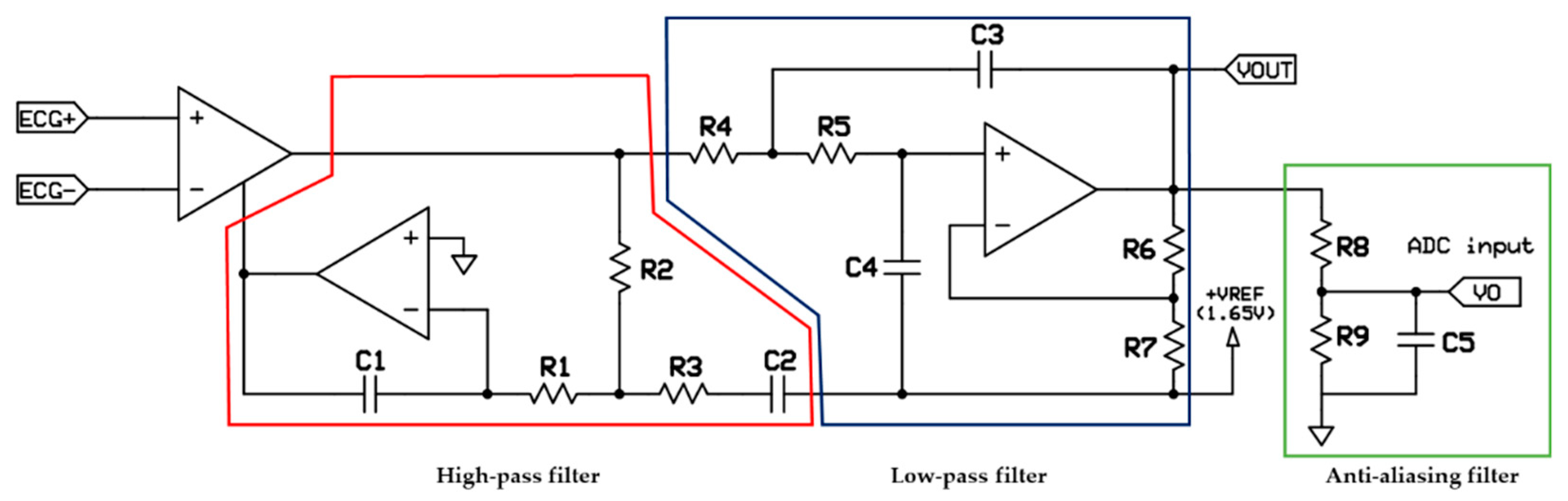
2.1.2. Front-End ECG Amplifier Configuration

A typical ECG signal acquisition system contains several chained stages of amplification and filtering blocks (see Figure 3). First, an instrumentation amplifier (INA) receives the differential signals captured by the sensing electrodes, through a patient-protection circuit block. This stage often provides low amplification (G1) and it is followed by a high-pass filtering amplifier block (HPF) and a second amplifier stage (G2). Finally, a low-pass filter (LPF) reduces the signal bandwidth according to the ECG frequency range before going into an analog-to-digital converter (ADC) subsystem connected or embedded in a microcontroller (MCU). In many applications, a right leg drive (RLD) amplifier circuit is used to reduce the common-mode interference, in order to enhance the overall front-end system performance. In a classical scheme of ECG acquisition, each block is implemented using several discrete components.
Currently, ECG acquisition systems are developed using specialized analog front-end (AFE) circuits, which combine the functionality of multiple signal processing blocks into a single integrated circuit. Table 1 summarizes the main specifications for various commercially available integrated circuits for developing ECG acquisition systems.
Some AFE solutions like ADS129X and ADS119X family chips (Texas Instruments Inc., Dallas, TX, USA) or ADAS1000-3 (Analog Devices, Inc., Norwood, MA, USA) offer high integration opportunities, but their use requires higher post-processing, imposing a heavier computational load over the microcontroller. According to the results of previous studies, the upper-arm ECG signal is expected to be noisy and presents a low-amplitude signal level [3], therefore a high total analog gain and high DC blocking capacity are required. Additionally, the above-mentioned circuits have a multiple ECG inputs channel, which is not necessary for our design purpose. In devising the targeted arm-ECG sensor system, we considered the AD8232 and AD8233 (Analog Devices, Inc., Norwood, MA, USA) as the most convenient options. The AD8232 analog front-end can be manually fixed, hence more convenient for rapid prototyping; also, its use has been reported to achieve satisfactory performance [10,11,26]. The AD8232 contains a high-quality instrumentation amplifier with a fixed gain of 100 V/V, capable to amplify very small signals and provide electrode offset rejection up to ±300 mV.
The filtering topologies, cut-off frequencies and gain can be adjusted by changing a few passive components. In our sensor, the AD8232 was configured to implement a two-pole high-pass filter followed by a two-pole low-pass filter, with cutoff frequencies of 0.5 and 40 Hz, respectively. Using this setup is expected to reduce motion artifacts, ECG signal baseline wandering and higher-frequency EMG (electromyogram) components to tolerable levels, avoiding amplifier saturation. However, it is contemplated that significant EMG noise will appear in the arm-ECG signals depending on the user’s physical activity.
From the schematic depicted in Figure 4, the filters’ cut-off frequencies were calculated using the expressions in Equation (1).
f h p = 10 2 π R 1 R 2 C 1 C 2 f l p = 1 2 π R 4 R 5 C 3 C 4
The additional gain in the low-pass filter stage is given by Equation (2). The values of the resistors were chosen to set a system total gain of 1100 V/V, resulting in a differential input range of ±1.5 mV. The system resolution using a 10-bit analog-to-digital converter is 2.93 uV.
A l p = 1 + R 6 / R 7
A step-down resistor network with an additional one-pole RC anti-aliasing filter was used to interface the AD8232 to the microcontroller. Thus, the circuit design matches the microcontroller’s allowed input signal amplitude range, while avoiding unwanted high-frequency noise from the digital peripheral devices affecting the digitization process.

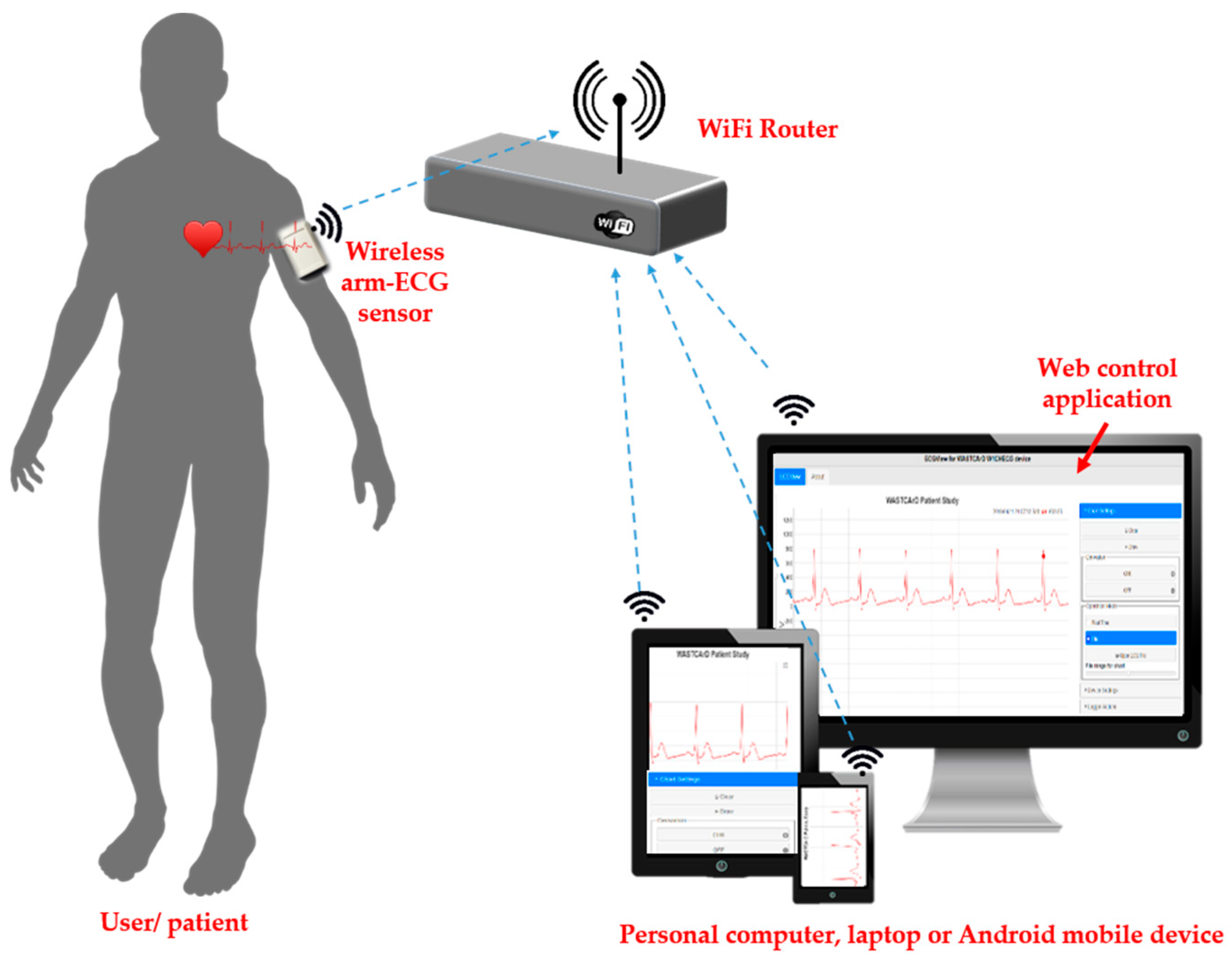
2.2. Overall System Architecture

The developed system consists of an arm-wearable sensor band, named WAMECG1, with a configured analog front-end amplifier for signal conditioning, an embedded processor with local storage and wireless communication capability, and the software (ECGView) required for its configuration and operation. The general architecture, shown in Figure 5, indicates the system operates in infrastructure network mode, requiring the existence of an access point (Wi-Fi router), the wearable arm sensor and a personal computer, laptop or smartphone.
The WAMECG1 prototype device, based on the ESP8266 system on a chip, is configured as a standard Wi-Fi station. It implements an HTTP server, which is available to other devices within the same WLAN network, allowing the sensor to be easily configured and monitored. Only one HTTP client (computer or smartphone) can be served (connected to the sensor) at a time. Once the system has been configured and the ECG acquisition started, it is able of recording the arm-ECG signal continuously up to 72 h (limited by battery size and power consumption). Afterwards, the Wi-Fi connection is no longer required until the data are going to be downloaded for further analysis.

2.2.1. Main Operational Features

The system supports two modes of operation:
  • Real-Time (monitor function): In this operation mode, the arm-ECG signal is acquired but not stored in the internal memory. Instead, it is sent to a connected client (computer or smartphone) for visualization. The main purpose of this operation mode is to initially ensure there is a good quality signal and correct skin–electrode contact before starting a longer-time recording.
  • File (Holter function): The sensor acquires and stores the left-arm ECG signal in its internal memory. Later, the data can be downloaded to a personal computer or smartphone using a standard Web browser and the developed ECGView application. This is the default operation mode.

2.2.2. Data Storage Protocol

Binary encoded files have been the predominant method for ECG data storage [27]. The main advantage of this approach is the reduced storage space required for its implementation, having significant value in resource-constrained embedded applications.
The European Data File format (EDF) is a simple binary format for storage and exchange of biological signals [28]. This format was chosen due to its simplicity to implement using an embedded platform. Once created, only one field of the record header in the EDF file has to be updated when appending a new data record. Moreover, the original file format and its subsequent version have been widely accepted as industry standards, with plenty of existing software tools available to manage this type of files.

2.2.3. Wireless Communication Technology

In recent years, Bluetooth, ZigBee, radio frequency identification (RFID) and Wi-Fi have been used for wireless communications in healthcare monitoring applications [6]. Table 2 summarizes recent works in wireless ECG monitoring systems. We discarded using ZigBee and similar ISM proprietary band transceivers (based on IEEE 802.15.4 standard) since these devices offer low data transfer rates and they are not factory available in smartphones and personal or laptop computers. Furthermore, they require the installation of additional hardware, thus increasing costs and limiting the portability of the design.
Bluetooth transceivers surpass Wi-Fi radios in terms of power consumption, making Bluetooth-based wireless solutions more efficient in battery usage. On these systems, both devices (ECG sensor and the base station) have to be paired before start exchanging data, and typically, they must remain connected while in operation. In this scenario, the wearable sensor is dependent on the communication infrastructure, not being able to operate as a stand-alone device. On the other hand, while the communication data rate in commercial off-the-shelf Bluetooth modules is usually under 1 Mbps, Wi-Fi radios have higher data rate and transmission range making them a better choice for transmitting large volumes of data, as was required for our design.

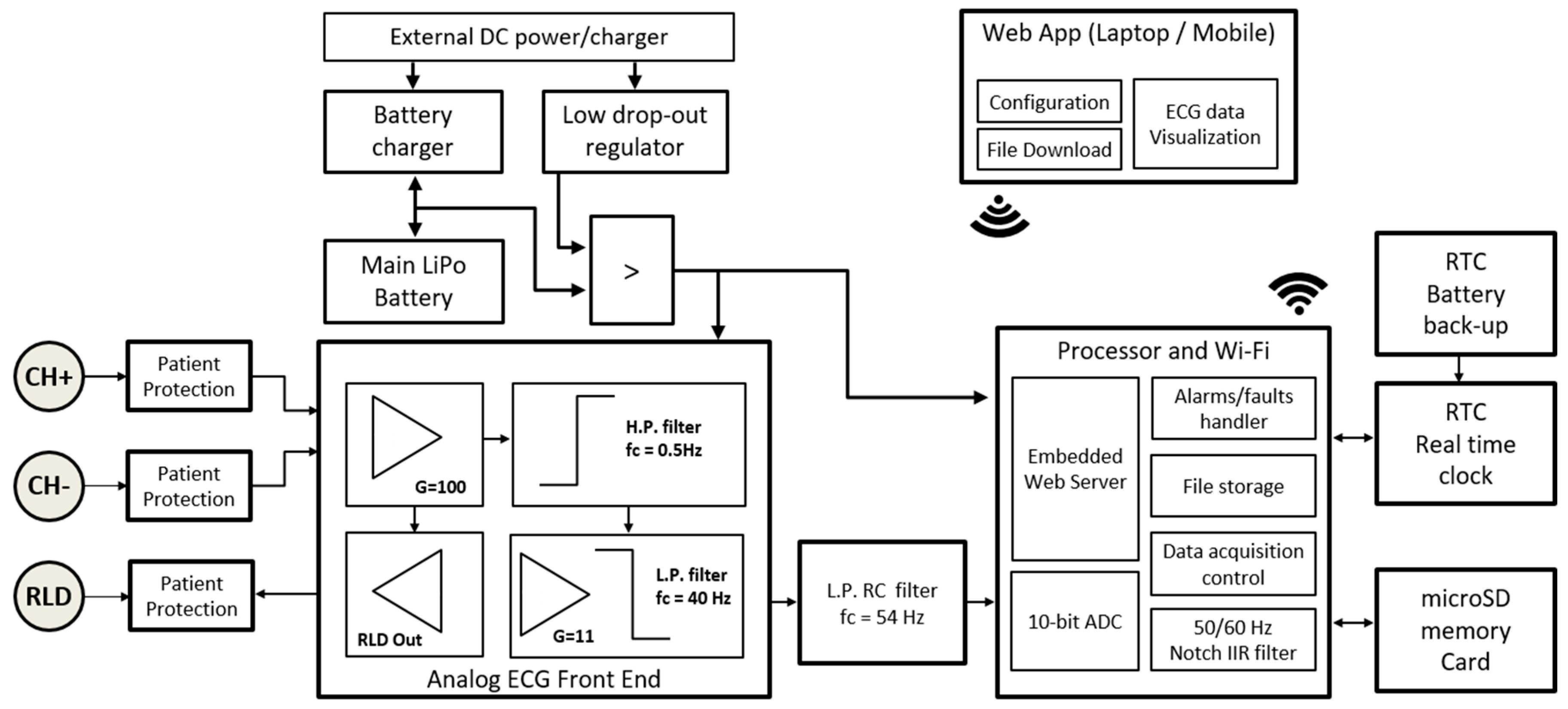
2.3. Hardware Design

The arm-ECG wireless sensor system shown in Figure 6 includes three main blocks of hardware: (a) the power supply and battery management; (b) the ECG sensors and analog acquisition front-end, as described above; and (c) the digital processor and wireless communication block.

2.3.1. Power Supply and Battery Management

The system is powered from a single 2300 mAh, 3.7 V LiPo battery and includes a battery charger with a low-dropout regulator to provide a clean power supply for the components. The battery charger was implemented using the MCP73831 charge management controller circuit (Microchip Technology Inc., Chandler, AZ, USA), which offers three charging modes: pre-conditioning or trickle charge, constant-current and constant-voltage. During the charging process the battery can reach up to 4.232 V; ECG amplifying circuitry and microcontroller unit used in this design operate at 3.3 V, therefore the use of an efficient, low-dropout and low-noise 3.3 V regulator was required. For this purpose, we selected the LP2989 integrated circuit (Texas Instruments Inc., Dallas, TX, USA). This component requires only four external passive components to operate, supplies a maximum current of 500 mA (typical dropout of 310 mV) with a load regulation of 0.4% and a voltage accuracy of 0.75%, meeting the power requirements of our sensor system.

2.3.2. Digital Processor and Wireless Communication Management

The system proposed was developed using the ESP8266EX (Espressif Systems, Shanghai, China) as a digital processor. The ESP8266 is a low-cost system on a chip (SoC), including a high performance 32-bit RISC processor and 802.11/b/g/n radio transceiver. It has been widely used for the rapid development of smart sensors applications and IoT solutions. The module can perform as a slave with another host microcontroller or a standalone system inasmuch as the Wi-Fi stack leaves up to 80% of the processing capabilities available for user application. The microcontroller core includes a Tensilica LX106 ultra-low-power 32-bit processor capable to operate up to 160 MHz with support for floating-point unit, digital signal processing, and 64 KB + 96 KB RAM memory. Its technical specifications, performance and low-cost have made the device competitive to other architectures, especially in the IoT market. The ESP8266 can be programmed in several platforms and programming languages including, C/C++, MicroPython and LUA, among others. The operation of the arm-ECG wireless sensor also required additional hardware peripherals such as a real-time clock (RTC) with independent battery backup, allowing the system to store a timestamp for the ECG data, and a micro SD memory card to store all the arm-recorded ECG data. The maximum allowable storage capacity is 32 GB.

2.3.3. Printed Circuit Board Design and Fabrication

The electronic schematic and printed circuit boards were created using the open-source design suite KiCad EDA (http://kicad-pcb.org/). The double-layer board was manufactured in standard 1.6 mm FR4 laminate with 1 oz copper weight. The board has a total dimension of 40 mm × 53 mm, being small enough to fit alongside the rechargeable Li-Po battery, connectors and other components in a commercially available PVC ergonomic wearable enclosure, as shown in Figure 7a. Figure 7b shows the top and bottom views of the assembled prototype and the final placement of the electrodes.

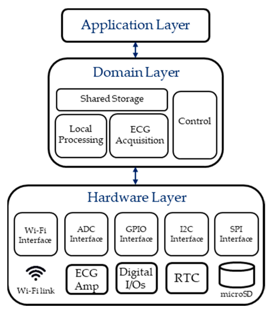
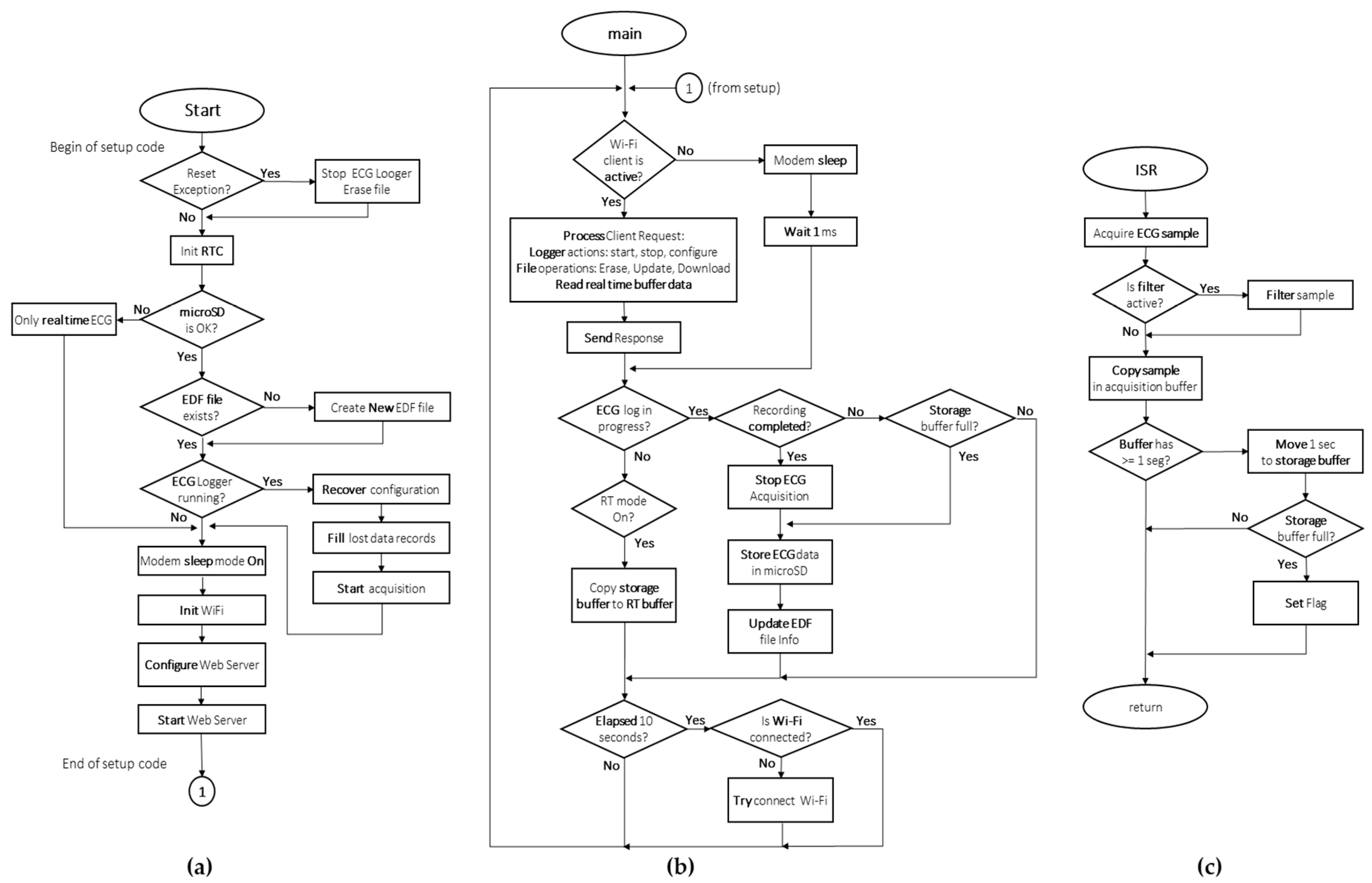
2.4. Firmware Architecture

A three-layer structure approach containing the Hardware, Domain and Application layers was adopted for the firmware architecture (see Figure 8). The Hardware layer includes all interfaces and low-level drivers required to handle the different hardware elements including analog-to-digital converter, digital inputs/outputs, Wi-Fi radio, real-time clock and micro SD memory card. The Hardware layer communicates only with the Domain layer. The Domain layer was implemented using a blackboard design pattern, with a shared storage memory space where the ECG acquisition and local processing sub-layers perform read or write operations. Shared memory accesses and operations within this layer are controlled and timed by a Control module. Finally, the Application layer controls the overall firmware behavior.

2.4.1. Firmware Algorithm

The ESP8266 firmware was implemented using the Arduino Core for ESP8266. This platform allows directly programming the ESP8266 using most of the standard Arduino libraries, accelerating the time required for prototyping. It also contains specific software libraries for configuring and controlling the Wi-Fi setup and data transmission protocols. Figure 9 presents a flowchart diagram describing the firmware algorithm for the system. On power-up, or after a reset, the microcontroller checks the reset cause and validates the existing ECG data file. Subsequently, RTC and microSD memory card are initialized, and the recording configuration is recovered from the internal non-volatile RAM of the ESP8266. If this setting is valid, and there was a recording in progress, the system evaluates the starting time and fills the resulting recording with zeros, if necessary. This was implemented to allow the system to recover after an unexpected reset or power loss without losing all the data previously stored. In such a case, a segment filled with zeros will appear in the final data, corresponding to the reset or shutdown time, but most of the ECG data will be available. Afterwards, the Wi-Fi connection is initialized and the WebServer configured to handle the requests from the client application. The main loop of the microcontroller’s program is used for (a) handling the web client requests; (b) periodically verifying the Wi-Fi connection status and re-connecting if possible; (c) storing the arm-ECG data in the SD memory; and (d) handling the status indicator LED.
All the data acquisition is interrupt-driven following Figure 9c, with a selectable sample rate of 125, 250 or 500 samples per second. Each ECG sample is acquired, filtered (if configured) and stored in a temporal RAM buffer which holds one second of data. Every second, this acquisition buffer is copied to a secondary storage buffer capable of holding 5 to 10 s of information. When the storage buffer is full, a flag is activated, meaning that the data in the buffer can be written to the microSD memory and the system checks if the recording has reached its expected duration to stop the acquisition process. With the adoption of this dual buffer scheme, we aim to reduce the accesses made to the microSD card. Writing to the microSD card is the second most power-consuming operation in the system (only surpassed by Wi-Fi transmission). The action is also time-consuming and cannot be completed in a time smaller than the sampling period of the ECG signal, hence the need for buffering. With the above described firmware implementation, the storage buffer could be easily expanded, thus further reducing the accesses to the SD card, which could lead to better power consumption. However, this would reduce the amount of RAM available for the future incorporation of complex, real-time processing algorithms as is intended for this device.

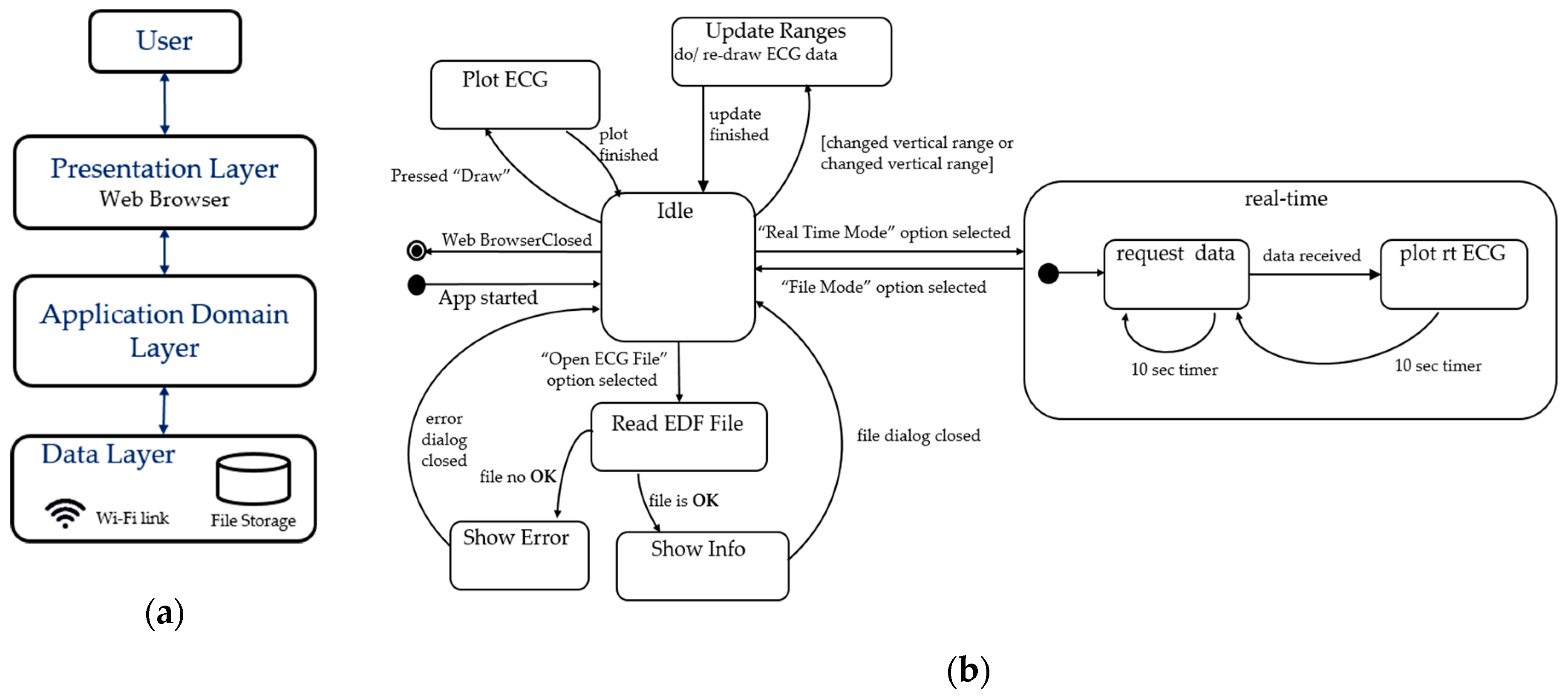
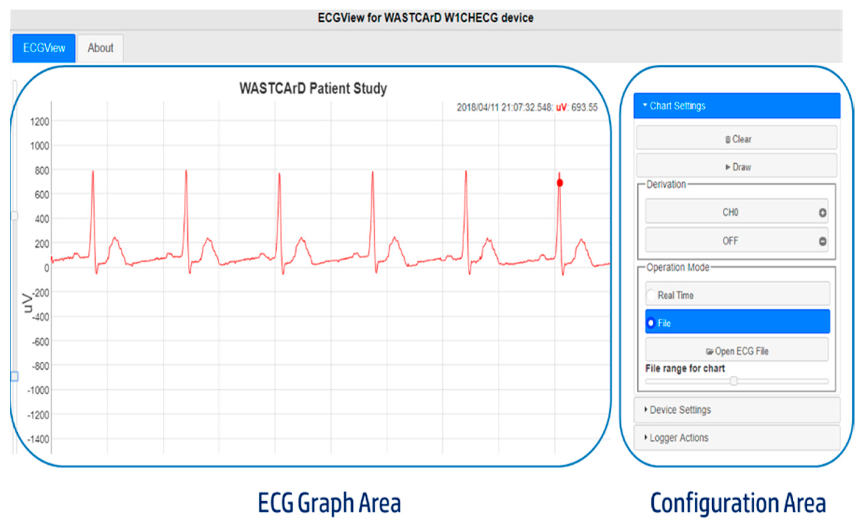
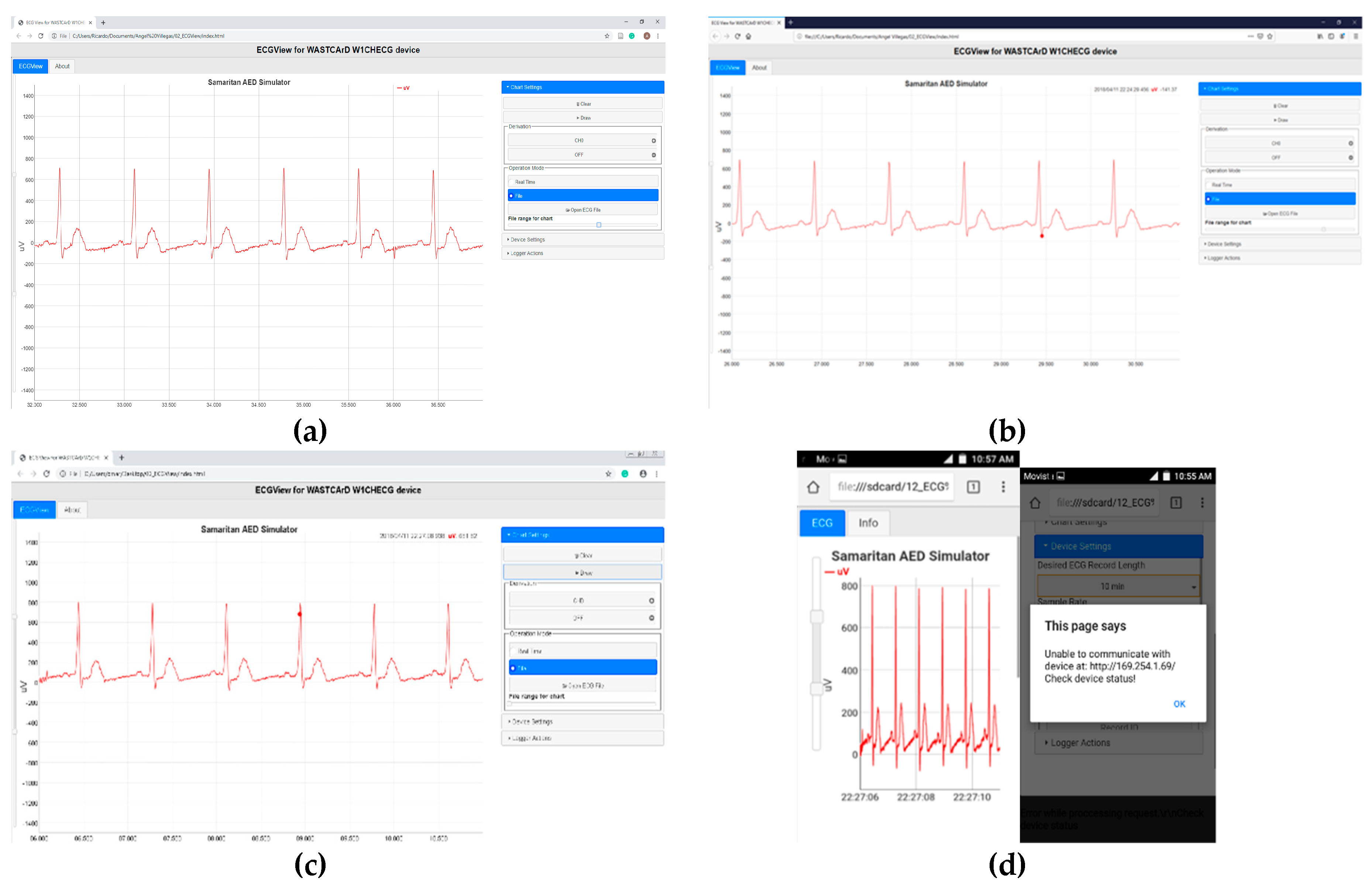
2.4.2. Real-Time Visualization and Control Sub-System

“ECGView” is a basic Web application developed as the data visualization tool for the arm-ECG sensor system (WAMECG1). Created using HTML, CCS and JavaScript programming languages, it can run on personal computers, laptops and Android tablets or smartphones. The application was designed using the three-layer architecture approach shown in Figure 10a. The Data layer is represented by both an ECG data file stored in the computer or mobile, and the Wi-Fi data link for real-time operation. It has the objects and functions to read/receive raw data and deliver them to the Application Domain. This layer processes the ECG data and prepares them for the Presentation layer, which displays the information on the user interface running over a web browser and handles the interaction with the user controls. The simplified state diagram depicted in Figure 10b describes the desired application behavior.
The main screen of the graphical user interface is divided into two parts: the ECG graph area on the left side of the screen and the configuration area on the right, as shown in Figure 11. The user can interact with the ECG graph area using a mouse or a touch controller, being able to manually adjust the Y-axis maximum/minimum values, zoom, pan or scroll the ECG trace for visual inspection, along with other user-friendly interactive functions. The configuration area allows the user to adjust different options including (a) select the system operation mode (real-time or file-based); (b) configure and clear the ECG graph; (c) define ECG acquisition parameters and update recording information; (d) set system’s real-time clock; and (e) start, stop or retrieve the arm-ECG data recording.

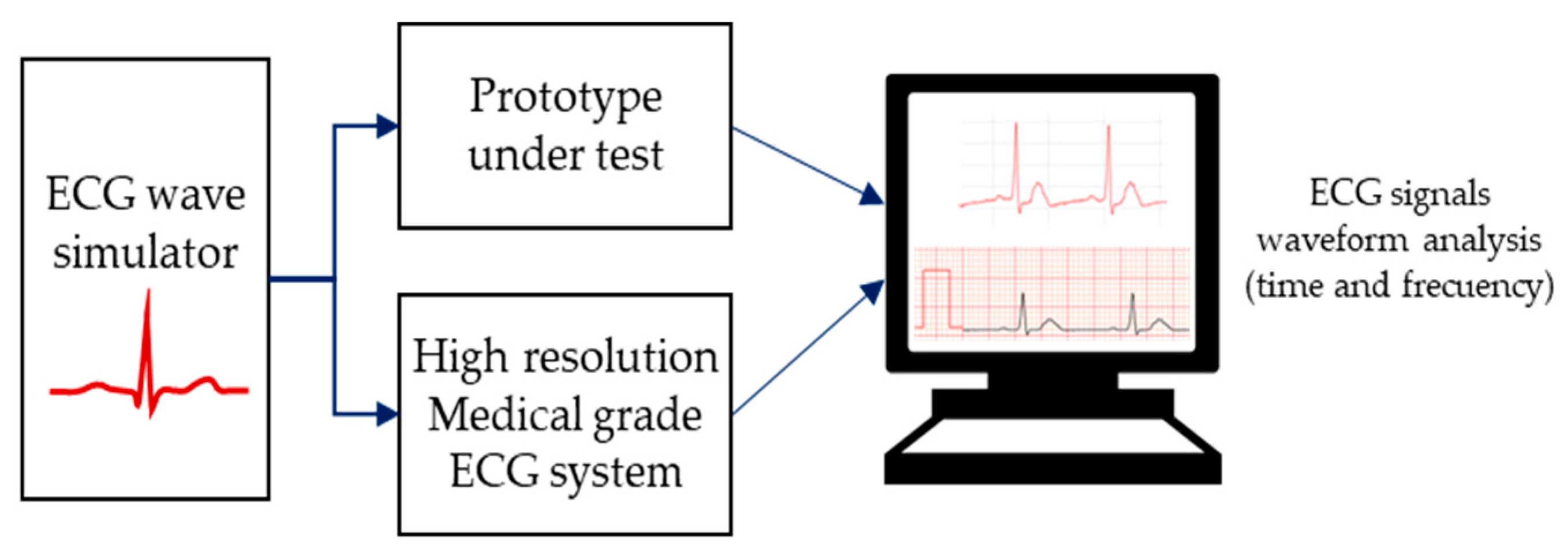
2.5. Device System Testing and Performance Assessment Methods

The performance validation of the sensor system was carried out in several steps. Firstly, a synthetic ECG signal was used to test the behavior of the electronic components, ensuring the signal was not distorted by the acquisition process. Amplitude and offset calibration was carried out using a high-resolution ECG acquisition system as reference. The second set of tests characterized several system performance parameters such as noise levels, common-mode rejection ratio, power-line interference rejection and average power consumption. Then, in-vivo measurements were conducted with a few subjects (members within the research team) wearing the arm-ECG sensor prototype while resting and performing low-level physical activities. The recorded signals were visually inspected and quantitatively analyzed to evaluate system performance. The following section describes the methods used to carry out these tests.

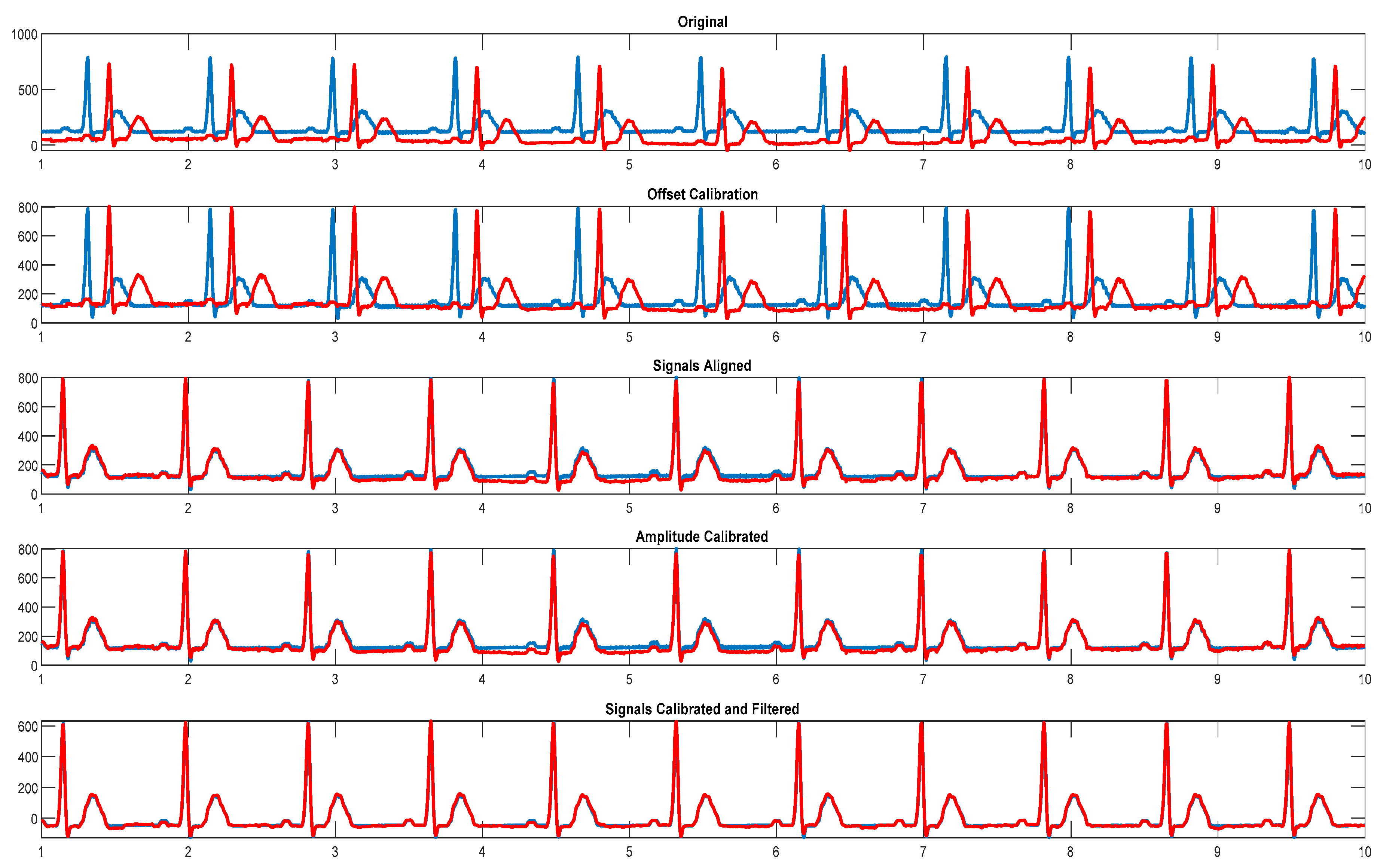
2.5.1. System Calibration and ECG Waveform Analysis

A synthetic normal sinus rhythm (NSR) signal, generated by using the Samaritan AED Simulator (Heartsine Technologies, San Clemente, CA, USA), was simultaneously applied to the arm-ECG sensor amplifier (WAMECG1 prototype) and to a high-resolution medical-grade ECG acquisition system ECG-1200HR (Norav Medical GmhH, Wiesbaden, Germany), as shown in Figure 12. Insomuch as the ECG-1200HR resolution is 0.305 uV and our system resolution is 2.93 uV, the high-resolution unit can be used as a reference to calibrate our system output. The procedure used for amplitude calibration was as follows:
  • The ECG signal is recorded on both devices for 60 seconds using a 250 Hz sampling rate.
  • Resulting files are imported into Matlab software (MathWorks, Natick, MA, USA).
  • Calculated mean value of the signals is used for offset correction.
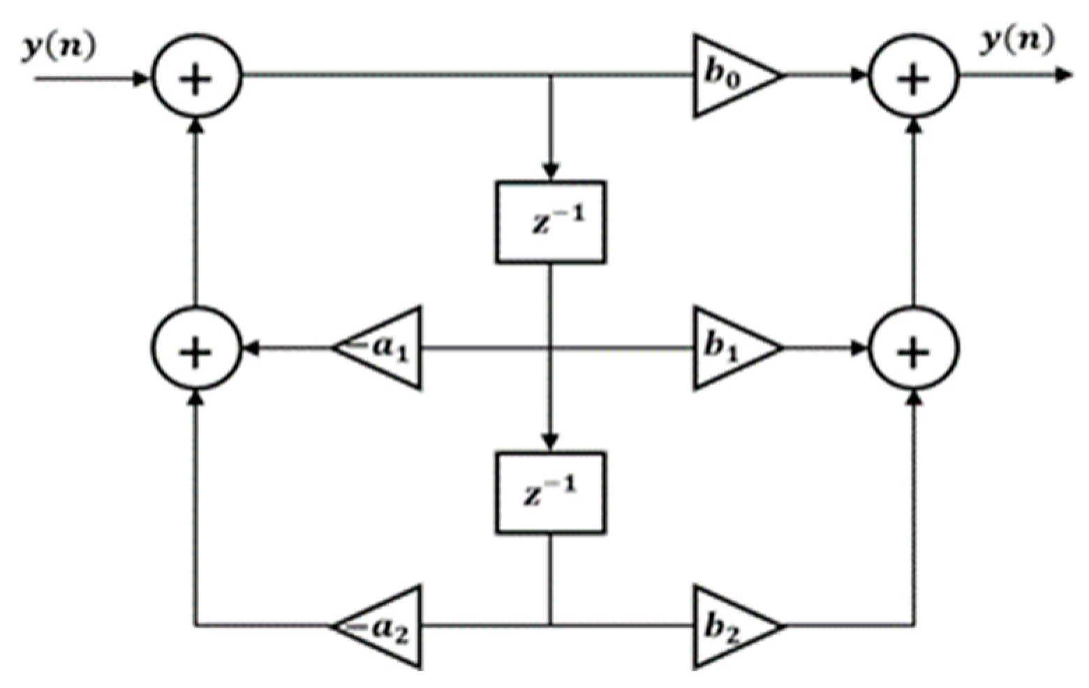
  • Signals are digitally filtered using a 50 Hz notch filter with 2.5 Hz bandwidth.
  • Signals are aligned using the normalized maximal cross-correlation between them.
  • Difference in amplitude values of the R-peaks and S-peaks (maximal QRS complex signal amplitude span) of the aligned ECG signals is used to calculate required scaling factor value. For this calculation a 1-second signal window was used.
  • The root-mean-square error (RMSE), mean absolute error (MAE) and cross-correlation coefficient (CC) are used as parameters to compare the similarity between signals after calibration.

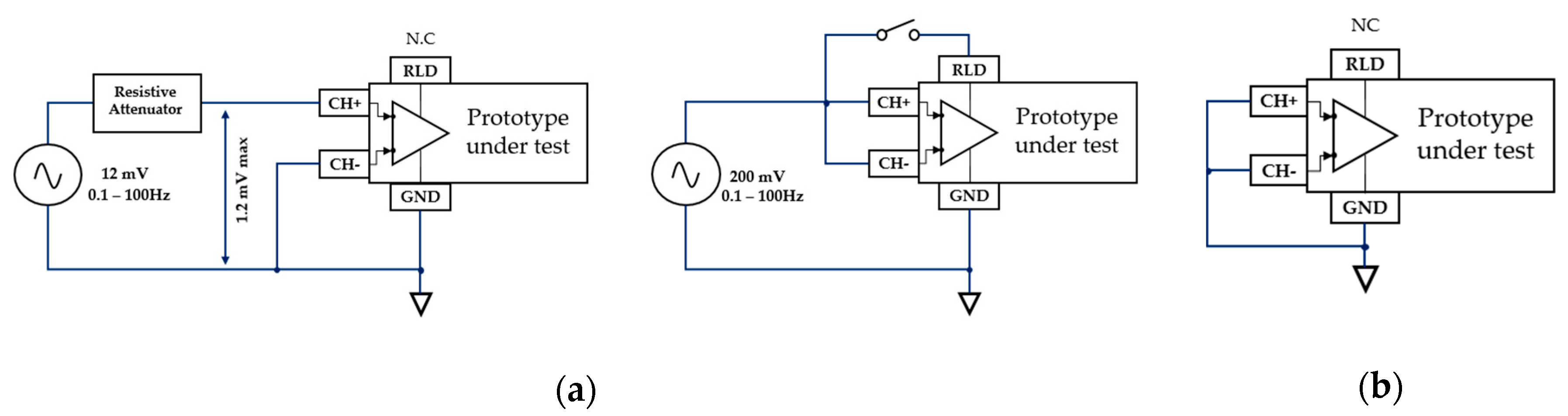
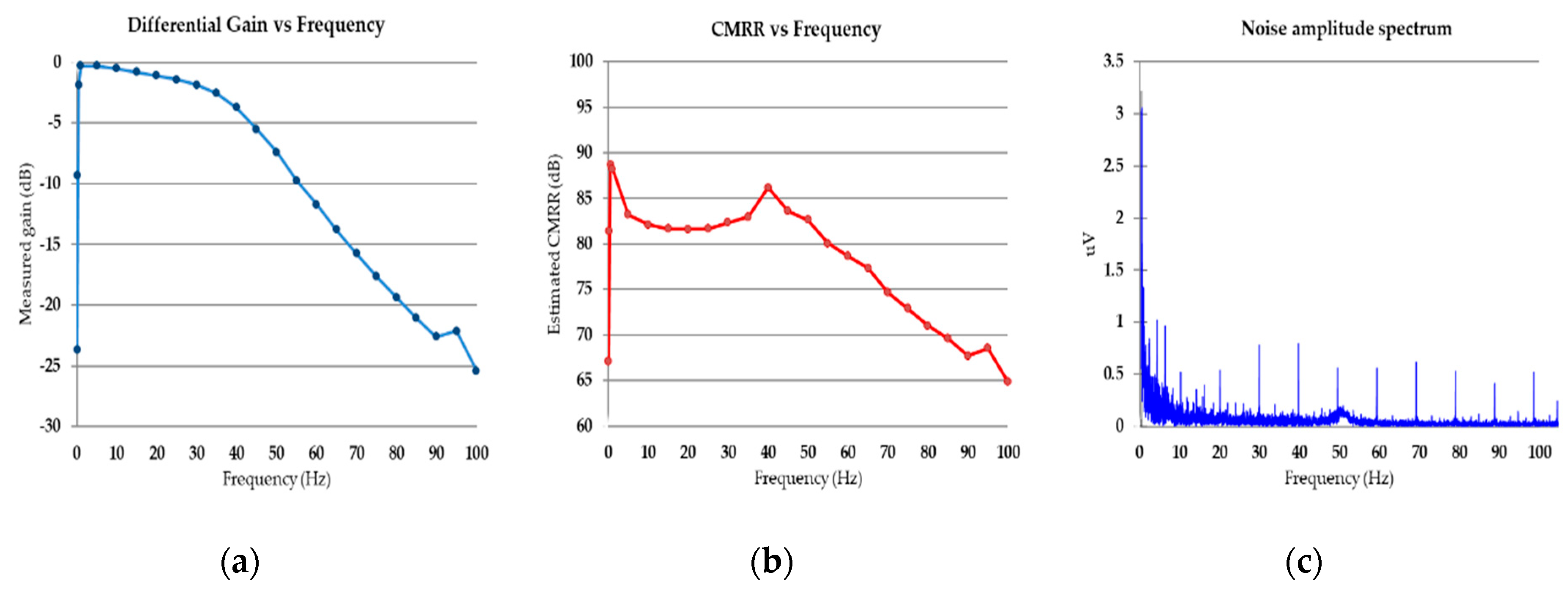
2.5.2. Amplifier Noise and CMRR Performance Assessment

The circuit block diagram presented in Figure 13a was used for CMRR calculation. A TG1010A direct digital synthesis function generator (Aim-TTi, Cambridgeshire, UK) provided a clean sine waveform input for the arm-ECG amplifier. Amplitudes were set to 12 and 200 mV (p-p) for the differential and common mode gain measurements, respectively. System response was measured and recorded for 20 seconds at 0.1, 0.25, 0.5 and 1 Hz and then in intervals from 5 to 100 Hz. A resistive network limited the maximum differential signal amplitude to 1.20 mV avoiding system saturation while measuring the differential gain (considering an estimated gain design of 1100 V/V).
To measure the input-referred noise, the circuit block diagram depicted in Figure 13b was used. Both amplifier inputs were shorted to ground, and the output was recorded with our ECG visualization application for a 1-minute duration. This circuit was also used to measure system offset.

2.5.3. R-peaks Detection Capacity from the Arm-ECG Signal

The ECG R-peaks are one of the most prominent features of the ECG waveform, therefore they are widely used in heartbeat segmentation algorithms required for automatic arrhythmias classification [36]. The interval between consecutive R-peaks (called the R-R interval) allows the determination of the heartbeat rate, and it is especially important for monitoring heart rate variability (HRV); thus the R-peak correct preservation was one of the principal goals of our arm-ECG sensor system.
Computational techniques for R-peak detection have been a well-studied area in the last three decades [36]. In this work, the single fiducial point (SPF) detection technique was adopted [37] and complemented with the rejection of possible closely adjacent R-peaks, as described in the difference operator method proposed by Yeh and Wang [38].
The accuracy of R-peaks identification from the bipolar lead signal gathered from the arm-ECG sensor was assessed using conventional criteria: sensitivity (Se), positive predictive value (PPV) and their combination in the F1-score. These were calculated using the expressions in Equation (3),
S e = T P T P + F N       P P V = T P T P + F P       F 1 s c o r e = 2 P P V * S e P P V + S e   ,  
where TP is the number of true R-peaks present, FP denotes the number of incorrectly labeled R-peaks and FN is the number of R-peaks not detected.

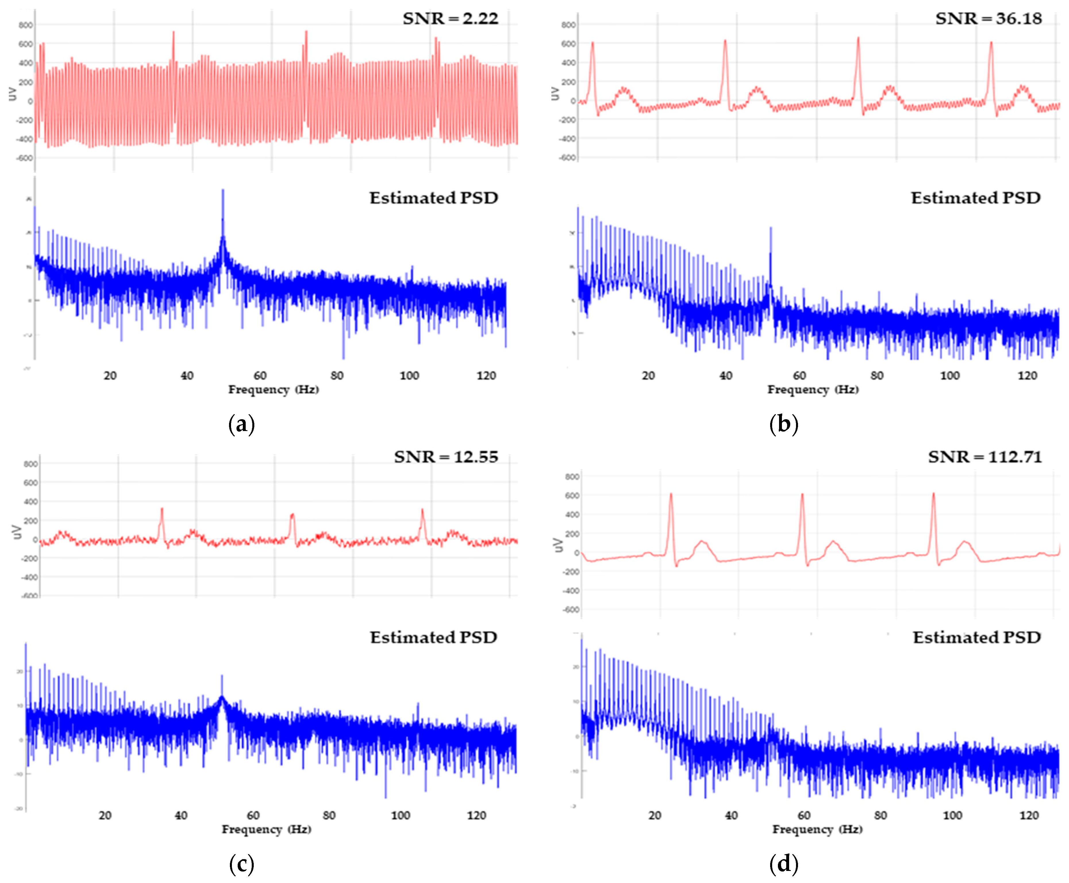
2.5.4. SNR Estimation on Recorded Signals

The signal-to-noise ratio (SNR) was selected as the comparison metric for evaluating arm-ECG signal quality obtained in this work. Lin et al. [3] previously described the general method used for SNR estimation. The procedure identifies two distinctive time areas of the ECG waveform. The first one is a 120 ms window, centered at the R-peak of the QRS complex waveform, which is considered as the main signal component. The second area is a window 40 ms wide, located in the iso-electric T-P segment of the ECG, considered as containing the pure background noise component in the ECG. As commented by Escalona et al. [4], it is not always possible to detect the T or P waves on the recorded ECG signal from the left upper arm, therefore, the reported approach there is by using a fixed time reference of 250 ms before the R-peak to locate the 40 ms noise estimation window. Then, the SNR is calculated as the standard deviation of the signal area divided by the standard deviation of the noise window [4], or alternatively, as the ratio of the maximum peak-to-peak voltages measured in the corresponding ECG activity estimation windows [5].

3. Results

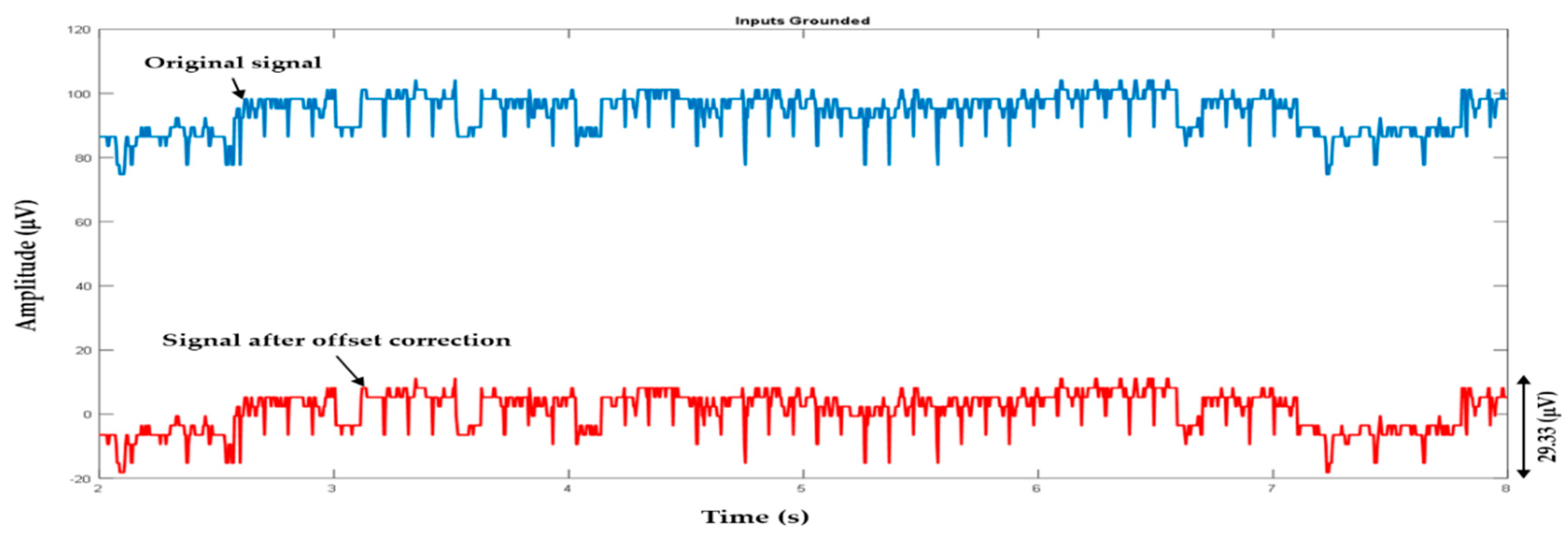
3.1. Initial Offset Adjustment and System Adquisition Tests

Figure 14 shows the signal recorded when the system inputs were tied to ground. The observed mean offset was 92.98 uV; we used this value as an initial calibration point. The calculated error was 6.91 uVrms, while the peak-to-peak maximal error was 29.33 uV (p-p). The overall functioning of the arm-ECG amplifier was tested at different sampling rates using a synthetic NSR waveform (see Figure 15). The system was capable of acquiring, storing and recovering the model ECG signal satisfactorily. Further analysis of the acquired signals included signal-to-noise ratio estimation, which was used as a validation metric for the ECG amplifying circuitry. Table 3 shows the average SNR achieved using raw data and data smoothed by a fourth-order moving average filter.

3.2. System Calibration and Functional Validation

The developed arm-ECG sensor system (WAMECG1) was calibrated using a high-resolution ECG clinical system ECG-1200HR as reference. All recordings were carried out in a regular laboratory ambient setting with no noise mitigation measures in place. Figure 16 presents the resulting traces through the different steps in the calibration procedure; from the original raw data to the final calibration step, the signals obtained with both systems were highly similar, as can be seen on the resulting over-imposed aligned traces. The measured offset was 17.23 uV, and an amplitude-scaling factor used to match the span of the signals was 1.0137. After calibration, the adjusted sensor signal showed a cross-correlation coefficient of 0.983 with the reference signal. The MAE was calculated and obtained as 18.19 uV, while the RMSE was 22.13 uV; these values represent the 0.6% and 0.74% of the sensor input range (fs), respectively. For additional verification, we applied a typical ECG pre-processing filter (second-order, zero-phase 0.5 to 40 Hz band-pass filter) on both input signals to the WAMECG1 sensor and the reference ECG-1200HR system, finding them visually indistinguishable. Table 4 shows the resulting improvement in all the comparison parameters after additional filtering.
The real-time visualization tool was tested in three hardware setups and using Google Chrome and Mozilla Firefox Web browsers to ensure the system is functional on different platforms, which are specified in Table 5. The software was able to communicate effectively with the arm-ECG sensor in each case, as illustrated in Figure 17, showing no dependence on the architecture and operative system used.

3.3. Front-End Amplifier Noise and CMRR Performance Assessment

Figure 18 summarizes assessment results for the differential gain (in dB), CMRR vs. frequency, and noise spectrum plots of the system from 0.1 to 100 Hz. The system gain was normalized considering the theoretical gain given by design (1100 V/V).
This experiment was not intended to comply with any regulatory standard like IEC-60601-2-27, but to serve as a mere estimation of the amplifier gain in the frequency band of interest and the verification of the CMRR value given by the AFE used in the design of the arm-ECG sensor system. The measured average CMRR in the band 0.5 to 60 Hz was 83.11 dB which is consistent with the range specified by the manufacturer (80 to 86 dB). This means that the passive components used in the circuit and the layout of the printed circuit board are suitable for the application.

3.4. Power-Line Noise Mitigation

Power-line noise interference signals (50 or 60 Hz) are coupled into the system in common mode. For this work, we incorporated two noise mitigation strategies typically found in ECG acquisition systems: (a) the use of right-leg drive circuit; and (b) noise removal by a digital notch filter. A two-pole digital infinite impulse response (IIR) filter was implemented in the acquisition firmware of the microcontroller using a Direct Form II structure (Figure 19), which is easy to implement for real-time embedded applications due to its low computational cost, allowing filtering the data samples as soon as they are acquired. The effectiveness of the results achieved using these power line denoising strategies for the case of 50 Hz is illustrated in Figure 20. For each case, the SNR was used as the indicator of the improvement in noise rejection.

3.5. Power Consumption, Authonomy and Other Specifications

The final experiments carried out were addressed to measure the average power consumption and wireless data transfer rate. The average power consumption of the system was measured in different operational conditions, as summarized in Table 6.
Measurements of the data transfer rate were estimated using recordings of 5, 30, 60 and 360 min long (see Table 7). Each file was downloaded ten times from the arm-ECG sensor to a laptop computer for average transfer time calculation. For this assessment test, a Cisco-Linksys WAP54G device (Linksys, Irvine, CA, USA) was used as a Wi-Fi access point. The achieved average transfer rate was 2.5 Mbps. Finally, Table 8 summarizes the achieved specifications for the devised arm-ECG wireless sensor system final WAMECG1 prototype.

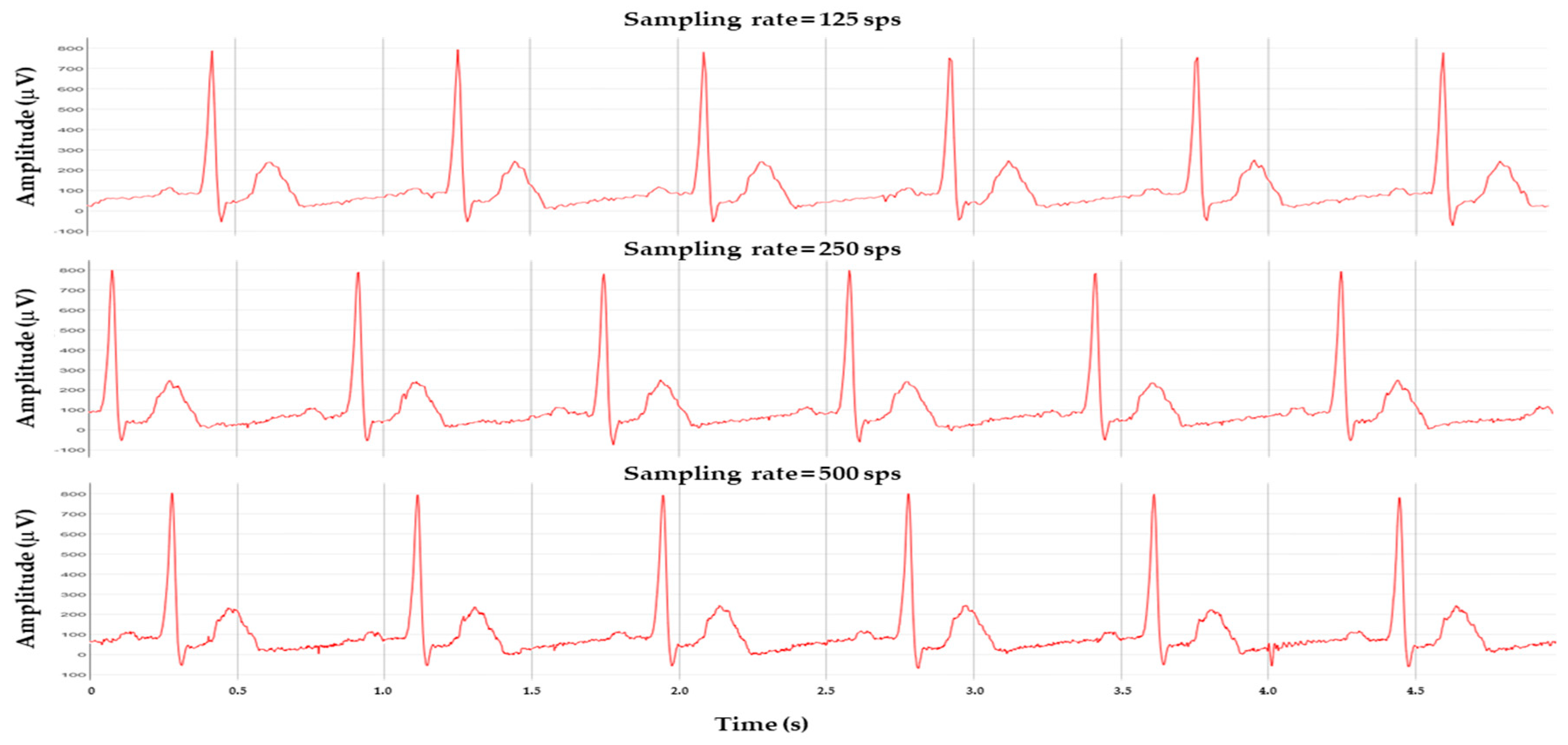
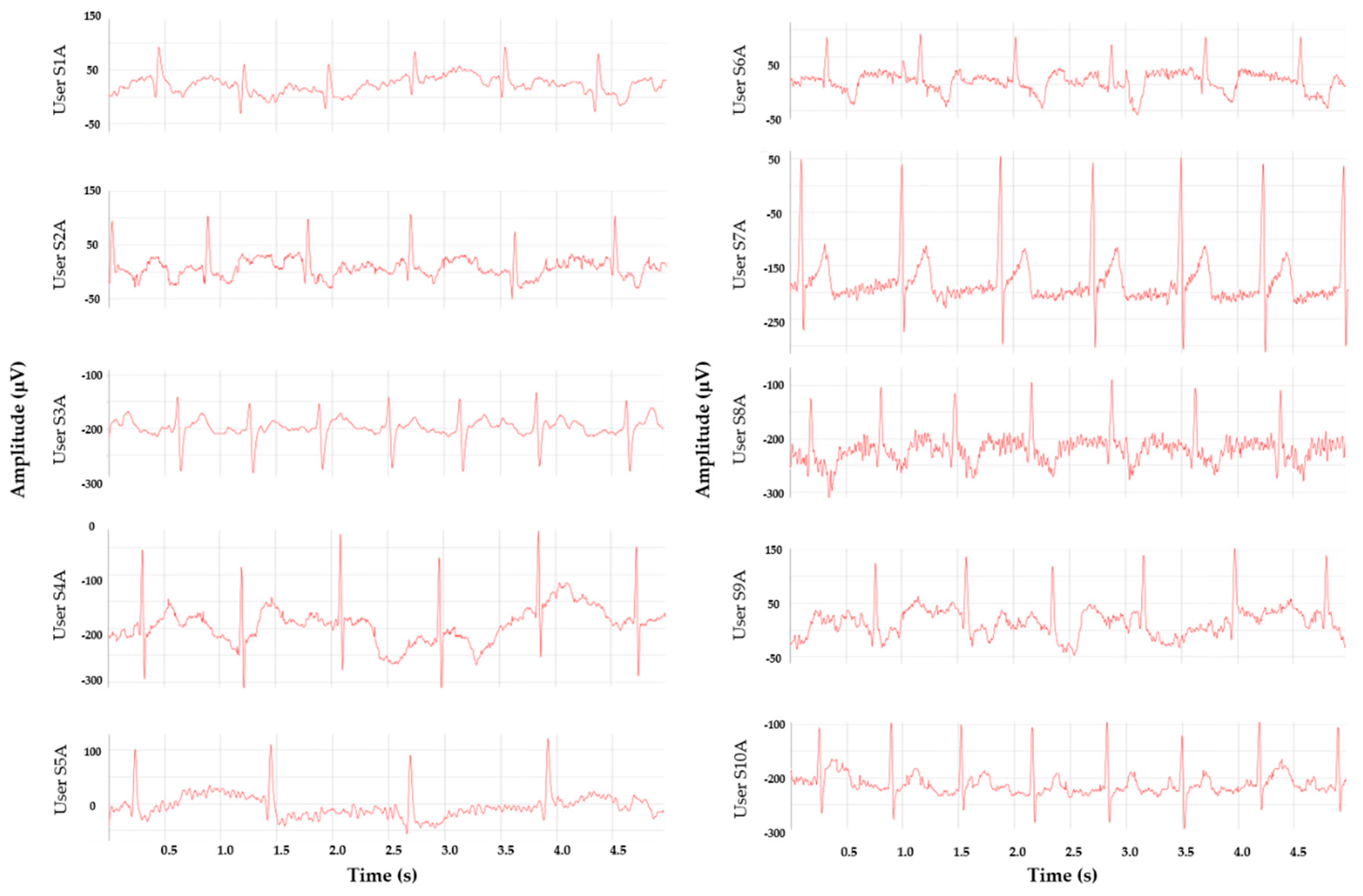
3.6. In-Vivo Arm-ECG Recordings Assessment Results

Once the initial bench assessments using the synthetic signal were finalized, some validation test arm-ECG recordings from volunteers, within the research team, were conducted. These recordings were aimed to test the following performance aspects: (a) the ability for recording a visually distinguishable arm-ECG signal; (b) the capacity to detect ECG R-peaks required for measuring R-R intervals in dynamic heartbeat rate calculations; (c) the user wearing comfort opinion; and (d) performance achieved while the subject is resting and while under low-level physical activities (e.g., doing some office work in a laboratory, or moderate walking). All subjects were recruited from within the research team and were agreeable to participate in the arm-ECG recording tests, and in accordance with the Declaration of Helsinki, with ethical approval HSC REC B (Health and Social Care, Research Ethical Committee, reference: 16/NI/0158), and IRAS (Integrated Research Application System, project ID: 203125).

3.6.1. Arm-ECG Signals while Resting

Ten male volunteers (average age 39.1 years old, standard deviation of 15.11) wore the WAMECG1 arm-ECG sensor band on their left arm, as shown in Figure 21. They were asked to sit in a chair for a 50-second recording; letting their arms rest naturally in a comfortable position, without making abrupt movements. Figure 22 shows sample strips of recorded bipolar arm-ECG lead signals for each of the 10 subjects. In all of them, it was possible to visually identify the R-peak and the structure of the QRS complex. The T wave was identifiable in 40% of the cases (4/10), while the P wave was not observed in any user. The R-peak detection (visual and automated) and SNR calculation results are presented in Table 9. The total number of detected R-peaks in the experimental data was 617, representing an error of +0.65% of the manually counted value (613).
There were substantial differences in the arm-ECG signal amplitudes among the subjects, ranging from 80 uV to 400 uV (p-p).

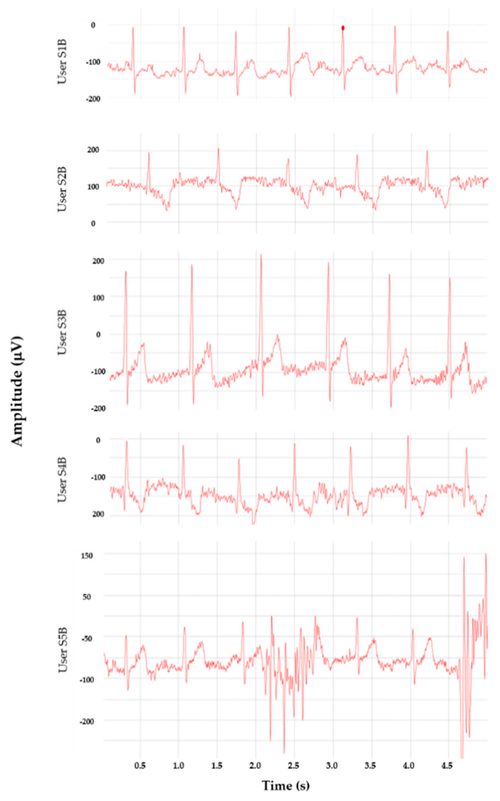
3.6.2. Arm-ECG Signals during Low-Level Physical Activity

As a final validation test, five subjects wore the arm-ECG sensor system during a longer recording time of one to two hours while doing their regular work at the laboratory facilities. They were asked to do their regular activities (mainly sitting in front of a computer or doing experiments with laboratory instruments) as usual, only trying not to jog or run while wearing the sensor. This test was aimed to assess the functionality of the system in a real-life scenario rather than systematically conducting pre-defined physical activities. After using the device, all volunteers agreed the device was comfortable to wear, even though their arms were different in size and thickness. Only one of them reported some minor discomfort, manifesting a low itching sensation caused by the elastic band of the sensor. Three users said they “had forgotten” about the fact of wearing the device after a few minutes. Figure 23 show segments of the arm-ECG signals recorded from these subjects. Depending on the particular subject’s activity level, it was possible to observe the presence of muscular and movement artefacts. Finally, a 10-minute-long data segment of each valid recording was selected for performance evaluation of the R-peak detection capacity and SNR calculations; the results are summarized in Table 10. The total number of manually counted R-peaks was 3104, while the system detected 3163 (a false R-peak detection error of +1.90%).

4. Discussion and Conclusions

In this work, we have presented a wireless sensor system capable of acquiring, storing and visualizing ECG signals recorded from bipolar leads on the left upper-arm. The final wearable sensor band prototype (WAMECG1) has a flexible adjustable belt strap, making it easy to adjust and providing a comfortable feeling for the user, according to the opinion reported by the subjects in the particular test results (80% experienced comfortable feeling). We consider this an important aspect of our design, given that it is aimed to be worn continuously over long periods.
A series of functional tests were completed to evaluate the behavior of the components in the system. These included simple calibration and verification experiments required to analyze and optimize the system implementation, in comparison to the targeted design specifications. Overall, the results evidenced an adequate performance of all the integral parts of the system, however, some key points were identified for future improvement upgrades in both hardware and software components.
After calibration, it was found that an ECG signal recorded with our system prototype showed no appreciable distortion when compared to the output of a reference medical-grade ECG recorder. A cross-correlation value of 0.997 and a maximum system error less than 0.75% of the input range confirmed the visual observations. The use of a simple fourth-order moving average filter yielded an average increment up to 32.44% in the signal-to-noise ratio when recording the synthetic ECG calibration signal. This result proved the convenience of incorporating this filter as part of the acquisition chain.
Compared with similar devices presented in the literature, our prototype has a lower power consumption than other Wi-Fi based systems [34,35] which is similar to results achieved by other systems using Bluetooth [13,31,32,33] and ISM wireless communication [19,29].
The portable low-power ECG/EMG sensor described in [39] has a convenient small size factor and can be worn on the chest (for ECG measurement) or in the arm (for EMG). However, the device did not provide any digitization, data storage, or wireless communication capabilities. The power consumption of this sensor was estimated as 350 uA, higher than the 300 uA drawn by the analog front-end used in our system (including external passive components). The wearable device presented by Celik et al. [40] uses graphene-coated electrodes attached behind the ear, upper neck, and left arm. The electrodes are wired to a measurement module placed on the arm. Compared with this device, our system is smaller and more convenient to use, requiring no extra wires or additional modules attached to the user’s body. Our device has more autonomy due to the use of a higher capacity battery since the estimated power consumptions are similar. The system proposed in [41] has the advantage of acquiring photoplethysmographic (PPG) and ECG signals simultaneously but is less portable, harder to set up, and does not offer wireless communication, keeping the user connected to a computer via USB port. It is worthwhile to note that none of the last-mentioned systems is capable of stand-alone operation, requiring a computer [41] or mobile phone [40] continuously connected for ECG data storing or monitoring, while stand-alone operation is an advantage found in our design.
We analyzed the ability of the system to recover a visually recognizable ECG trace in two different scenarios according to the user’s physical activity level. For the first scenario, the subjects were resting while sitting. The qualitative visual inspection of the arm-ECG waveforms under this condition showed clear and appreciable ECG traces, with eventual moving artefacts and low to moderate high-frequency noise. Despite there being significant differences in the arm-ECG signal amplitudes for all the users, the visual identification of the QRS complexes was successful in all cases. The automated R-peak detection algorithm achieved an average sensitivity of 99.66% with a positive predictive value (PPV) of 99.1%. These values point out that the recorded signal indeed can be used, with minimal post-processing, for heartbeat rate calculation and therefore for arrhythmia detection since the vast majority of the heartbeats were correctly located. We found that the digitized experimental in-vivo recorded signals exhibited a higher SNR than most of the average values reported (after applying advanced denoising technics) in [4,42] (See Table 9). This suggests that the signals acquired with the WAMECG1 prototype are better in quality (less noisy) than the signals used by the previous studies. It is expected that the future inclusion of some of the reported advanced denoising methods in the microcontroller firmware can greatly improve this parameter.
In the second testing scenario, five users were instructed to do their regular activities inside a research laboratory under ambient conditions while trying not to make sudden movements or strong muscular contractions on their left arm. Four of them (80%) followed the instructions for the required time, while one did more physical activity than expected, including going up and down stairs and rapidly walking across the laboratory facilities. The data from this last subject were not presented in Table 10, due to the presence of continuous muscular artefacts affecting the signal. In the recordings from the rest of the users, we observed the presence of multiple artefacts and noisy episodes as well. Nevertheless, the bipolar arm-ECG signal integrity was well-enough preserved for visual analysis. In this second testing scenario, the R-peak detection showed a sensitivity of 94.64% and a precision of 92.68%, with an increase of 1.25% in the detection error, evidencing a minor effectivity when comparing to the resting data. The maximum difference between the automatically detected R-peaks and the manual count was less than 2%, thus indicating that using the proper post-processing is possible to locate this feature from the recorded arm-ECG signal effectively.
The results indicate that the presence of muscular and electrode movement artefacts still represents a big issue for the developed prototype, as they are capable of contaminating the recorded signal at intolerable levels. We anticipate that the future implementation of more advanced denoising technics, as well the incorporation of sensors for motion and muscular activity measurements, will lead to better noise mitigation when the user is performing physical activities such as moderate walking. The inclusion of these additional real-time processing capabilities is possible since the current implementation has used less than 40% of the total program memory and 30% of the RAM available in the microcontroller.
We have successfully tested the functionality of the WAMECG1 sensor system in a small group of subjects. The results suggest that the bipolar far-field ECG bio-potentials, sensed by our prototype using transversally located electrodes on the left upper-arm, can be used for automatic heartbeat extraction as required in long-term arrhythmia monitoring. Nevertheless, we will require collecting additional experimental data from more, healthy and non-healthy subjects, performing different physical activities in future development stages for reliable heart rhythm analysis algorithms based on machine learning techniques. For the latter purpose (recognition of normal and abnormal ECG rhythms), the system will also require further optimization in physical size, power consumption and embedded implementation of additional signal enhancement techniques.
The major drawback of Wi-Fi-based healthcare monitoring systems, as in the WAMECG1 prototype, is power consumption. However, the average current drawn by the system (18 mA) is comparable to current approaches based on other high-performance microcontrollers and wireless communication technologies, as shown in Table 2. This value showed to be low enough to achieve the desired autonomy, fulfilling our initial requirements. We have used the less aggressive power reduction strategy available in the ESP8266 SoC, which only switches off the Wi-Fi radio momentarily, leaving the core-processing unit running at full speed. This allows our prototype to have a trade-off compromise between autonomy and performance, keeping the Web interface responsive in the monitoring mode while consuming less than 36 mA. For further power optimization, the ESP8266 implements another two low-power operation modes that switch the Wi-Fi radio off completely and stop the processor for long times. Although we found them not applicable to our development at this moment (because they would interfere with the data acquisition routines), their existence opens the possibility of using an additional ultra-low-power microcontroller as an auxiliary processor only for data acquisition. This would allow developing a solution capable of monitoring/recording a bipolar arm-ECG lead signal for several weeks.

Author Contributions

Initial conceptualization, O.E. and D.M.; electronics and programming, A.V.; writing—original draft preparation: A.V.; writing—review and final editing, O.E.; ethical procedures and clinical protocol design, D.M. All authors contributed equally to data analysis and interpretation of results.

Funding

This research was supported by funding from the European Union (EU): H2020-MSCA-RISE Programme (WASTCArD Project, Grant #645759). Professor Omar Escalona’s dedication to this study was supported by philanthropic funds; equally from the Ulster Garden Villages Ltd. and the McGrath Trust (UK).

Conflicts of Interest

The authors declare no conflict of interest.

References

  1. Katritsis, D.G.; Gersh, B.J.; Camm, A.J. A Clinical Perspective on Sudden Cardiac Death. Arrhythm. Electrophysiol. Rev. 2016, 5, 177–182. [Google Scholar] [CrossRef]
  2. Krahn, A.D.; Klein, G.J.; Skanes, A.C.; Yee, R. Insertable Loop Recorder Use for Detection of Intermittent Arrhythmias. Pacing Clin. Electrophysiol. 2004, 27, 657–664. [Google Scholar] [CrossRef]
  3. Lynn, W.D.; Escalona, O.J.; McEneaney, D.J. Arm and wrist surface potential mapping for wearable ECG rhythm recording devices: A pilot clinical study. J. Phys. Conf. Ser. 2013, 450, 3–8. [Google Scholar] [CrossRef]
  4. Escalona, O.J.; Lynn, W.D.; Perpiñan, G.; McFrederick, L.; McEneaney, D.J. Data-Driven ECG Denoising Techniques for Characterising Bipolar Lead Sets along the Left Arm in Wearable Long-Term Heart Rhythm Monitoring. Electronics 2017, 6, 84. [Google Scholar] [CrossRef]
  5. Escalona, O.; Mcfrederick, L.; Borges, M.; Linares Herrera, P.; Villegas, R.; Perpiñan, G.; McLaughlin, J.; Mceneaney, D. Wrist and Arm Body Surface Bipolar ECG Leads Signal and Sensor Study for Long-term Rhythm Monitoring. In Proceedings of the Computing in Cardiology (CinC), Rennes, France, 24–27 September 2017. [Google Scholar]
  6. Dey, N.; Ashour, A.S.; Shi, F.; Fong, S.; Sherratt, R. Developing Residential Wireless Sensor Networks for ECG Healthcare Monitoring. IEEE Trans. Consum. Electron. 2017, 63, 442–449. [Google Scholar] [CrossRef]
  7. Boehm, A.; Yu, X.; Neu, W.; Leonhardt, S.; Teichmann, D. A Novel 12-Lead ECG T-Shirt with Active Electrodes. Electronics 2016, 5, 75. [Google Scholar] [CrossRef]
  8. Chi, Y.M.; Jung, T.; Cauwenberghs, G. Dry-Contact and Noncontact Biopotential Electrodes: Methodological Review. IEEE Rev. Biomed. Eng. 2010, 3, 106–119. [Google Scholar] [CrossRef]
  9. Chowdhury, M.E.H.; Alzoubi, K.; Khandakar, A.; Khallifa, R.; Abouhasera, R.; Koubaa, S.; Ahmed, R.A.; Hasan, A. Wearable Real-Time Heart Attack Detection and Warning System to Reduce Road Accidents. Sensors 2019, 19, 2780. [Google Scholar] [CrossRef]
  10. Massot, B.; Hutu, F.; Gehin, C.; Noury, N. Design and Optimization of an Autonomous, Ambulatory Cardiac Event Monitor. In Proceedings of the IEEE 20th International Conference on e-Health Networking, Applications and Services (Healthcom), Ostrava, Czech Republic, 17–20 September 2018. [Google Scholar]
  11. Liu, S.; Cai, G.; Huang, Y.; Chen, Y. A wearable ECG apperatus for ubiquitous health care. In Proceedings of the IEEE International Conference on Systems, Man, and Cybernetics (SMC), Budapest, Hungary, 9–12 October 2016; pp. 4471–4476. [Google Scholar]
  12. Preejith, S.P.; Dhinesh, R.; Joseph, J.; Sivaprakasam, M. Wearable ECG platform for continuous cardiac monitoring. In Proceedings of the 38th Annual International Conference of the IEEE Engineering in Medicine and Biology Society (EMBC), Orlando, FL, USA, 16–20 August 2016; pp. 623–626. [Google Scholar]
  13. Rachim, V.P.; Chung, W. Wearable Noncontact Armband for Mobile ECG Monitoring System. IEEE Trans. Biomed. Circuits Syst. 2016, 10, 1112–1118. [Google Scholar] [CrossRef]
  14. Lynn, W.; Escalona, O.; McEneaney, D. A Low Latency Electrocardiographic QRS Activity Recovery Technique for Use on the Upper Left Arm. Electronics 2014, 3, 409–418. [Google Scholar] [CrossRef] [Green Version]
  15. Vizcaya, P.R.; Perpiñan, G.I.; McEneaney, D.J.; Escalona, O.J. Standard ECG lead I prospective estimation study from far-field bipolar leads on the left upper arm: A neural network approach. Biomed. Signal Process. Control 2019, 51, 171–180. [Google Scholar] [CrossRef]
  16. Gemperle, F.; Kasabach, C.; Stivoric, J.; Bauer, M.; Martin, R. Design for Wearability. In Proceedings of the ISWC Second International Symposium on Wearable Computers (ISWC’98), Pittsburgh, PA, USA, 19–20 October 1998; p. 116. [Google Scholar]
  17. Chen, C.-Y.; Chang, C.-L.; Chang, C.-W.; Lai, S.-C.; Chien, T.-F.; Huang, H.-Y.; Chiou, J.-C.; Luo, C.-H. A Low-Power Bio-Potential Acquisition System with Flexible PDMS Dry Electrodes for Portable Ubiquitous Healthcare Applications. Sensors 2013, 13, 3077–3091. [Google Scholar] [CrossRef]
  18. Aleksandrowicz, A.; Leonhardt, S. Wireless and Non-contact ECG Measurement System—The “Aachen SmartChair”. Acta Polytech. 2007, 47, 68–71. [Google Scholar]
  19. Nemati, E.; Deen, M.J.; Mondal, M. A Wireless Wearable ECG Sensor for Long-Term Applications. IEEE Commun. Mag. 2012, 50, 36–43. [Google Scholar] [CrossRef]
  20. Saponara, S.; Donati, M.; Fanucci, L.; Celli, A. An Embedded Sensing and Communication Platform, and a Healthcare Model for Remote Monitoring of Chronic Diseases. Electronics 2016, 5, 47. [Google Scholar] [CrossRef]
  21. Meziane, N.; Webster, J.G.; Attari, M.; Nimunkar, A.J. Dry electrodes for electrocardiography. Physiol. Meas. 2013, 34, 47–69. [Google Scholar] [CrossRef]
  22. Bosnjak, A.; Kennedy, A.; Linares, P.; Borges, M.; McLaughlin, J.; Escalona, O.J. Performance assessment of dry electrodes for wearable long term cardiac rhythm monitoring: Skin-electrode impedance spectroscopy. In Proceedings of the 39th Annual International Conference of the IEEE Engineering in Medicine and Biology Society (EMBC), Seogwipo, Korea, 11–15 July 2017; pp. 1861–1864. [Google Scholar]
  23. Hoffmann, K.; Ruff, R.; Poppendieck, W. Long-Term Characterization of Electrode Materials for Surface Electrodes in Biopotential Recording. In Proceedings of the International Conference of the IEEE Engineering in Medicine and Biology Society, New York, NY, USA, 30 August–3 September 2006; pp. 2239–2242. [Google Scholar]
  24. Tallgren, P.; Vanhatalo, S.; Kaila, K.; Voipio, J. Evaluation of commercially available electrodes and gels for recording of slow EEG potentials. Clin. Neurophysiol. 2005, 16, 799–806. [Google Scholar] [CrossRef]
  25. Neuman, M.R. Biopotential Electrodes. In Medical Instrumentation: Application and Design; Webster, J.G., Ed.; John Wiley & Sons: Hoboken, NJ, USA, 2010; pp. 189–241. [Google Scholar]
  26. Gifari, M.W.; Zakaria, H.; Richard, M. Design of ECG Homecare: 12-lead ECG acquisition using single channel ECG device developed on AD8232 analog front end. In Proceedings of the International Conference on Electrical Engineering and Informatics (ICEEI), Denpasar, Indonesia, 10–11 August 2015; pp. 371–376. [Google Scholar]
  27. Bond, R.R.; Finlay, D.D.; Nugent, C.D.; Moore, G. A review of ECG storage formats. Int. J. Med Inform. 2011, 80, 681–697. [Google Scholar] [CrossRef]
  28. Kemp, B.; Värri, A.; Rosa, A.C.; Nielsen, K.D.; Gade, J. A simple format for exchange of digitized polygraphic recordings. Electroencephalogr. Clin. Neurophysiol. 1992, 82, 391–393. [Google Scholar] [CrossRef]
  29. Gaxiola-Sosa, J.E.; Nasreen Mohsin, A.J.; Palliyali, R.T.; Kamran, E. A PorTable 12-Lead ECG Wireless Medical System for Continuous Cardiac-Activity Monitoring. In Proceedings of the IEEE Middle East Conference on Biomedical Engineering (MECBME), Doha, Qatar, 17–20 February 2014; pp. 123–126. [Google Scholar]
  30. Lee, S.H.; Jung, S.M.; Lee, C.K.; Jeong, K.S.; Cho, G.; Yoo, S.K. Wearable ECG Monitoring System Using Conductive Fabrics and Active Electrodes. In International Conference on Human-Computer Interaction; Springer: Berlin/Heidelberg, Germany, 2009; pp. 778–783. [Google Scholar]
  31. ElSaadany, Y.; Majumder, A.J.A.; Ucci, D.R. A Wireless Early Prediction System of Cardiac Arrest through IoT. In Proceedings of the IEEE 41st Annual Computer Software and Applications Conference, Turin, Italy, 4–8 July 2017. [Google Scholar]
  32. Touati, F.; Tabish, R.; Mnaouer, A.B. A Real-Time BLE enabled ECG System for Remote Monitoring. APCBEE Procedia 2013, 7, 124–131. [Google Scholar] [CrossRef]
  33. Pineda-López, F.; Martínez-Fernández, A.; Rojo-Álvarez, J.L.; García-Alberola, A.; Blanco-Velasco, M. A Flexible 12-Lead/Holter Device with Compression Capabilities for Low-Bandwidth Mobile-ECG Telemedicine Applications. Sensors 2018, 18, 3773. [Google Scholar] [CrossRef] [PubMed]
  34. Ahammed, S.S.; Pillai, B.C. Design of Wi-Fi Based Mobile Electrocardiogram Monitoring System on Concerto Platform. Procedia Eng. 2013, 64, 65–73. [Google Scholar] [CrossRef] [Green Version]
  35. Khalaf, A.; Abdoola, R. Wireless Body Sensor Network and ECG Android Application for eHealth. In Proceedings of the Fourth International Conference on Advances in Biomedical Engineering (ICABME), Beirut, Lebanon, 19–21 October 2017. [Google Scholar]
  36. Luz, E.J.D.S.; Schwartz, W.R.; Cámara-Chávez, G.; Menotti, D. ECG-based heartbeat classification for arrhythmia detection: A survey. Comput. Methods Programs Biomed. 2016, 127, 144–164. [Google Scholar] [CrossRef] [PubMed]
  37. Escalona, O.J.; Mitchell, R.H.; Balderson, D.E.; Harron, D.W. Fast and reliable QRS alignment technique for high-frequency analysis of signal-averaged ECG. Med. Biol. Eng. Comput. 1993, 31, 137–146. [Google Scholar] [CrossRef]
  38. Yeh, Y.C.; Wang, W.J. QRS complexes detection for ECG signal: The Difference Operation Method. Comput. Methods Programs Biomed. 2008, 91, 245–254. [Google Scholar] [CrossRef]
  39. Jani, A.B.; Bagree, R.; Roy, A.K. Design of a low-power, low-cost ECG & EMG sensor for wearable biometric and medical application. In Proceedings of the IEEE SENSORS, Glasgow, UK, 29 October–1 November 2017; pp. 1–3. [Google Scholar] [CrossRef]
  40. Celik, N.B.W.; Manivannan, N.; Winter, E.; Schnalzer, B.; Burgsteiner, H. Wearable mobile ear-based ECG monitoring device using graphene-coated sensors. In Proceedings of the IEEE SENSORS, Glasgow, UK, 29 October–1 November 2017. [Google Scholar]
  41. Vinciguerra, V.A.E.; Maddiona, L.; Romeo, M.; Mazzillo, M. PPG/ECG Multisite Combo System Based on SiPM Technology. In Convegno Nazionale Sensori; Springer: Cham, Switzerland, 2018. [Google Scholar]
  42. Lynn, W.D.; Escalona, O.J.; Vizcaya, P.R.; McEneaney, D.J. Arm-ECG bipolar leads signal recovery methods for wearable long-term heart rate and rhythm monitoring. In Proceedings of the Computing in Cardiology (CinC), Rennes, France, 24–27 September 2017. [Google Scholar]
Figure 1. Suggested electrode locations for electrocardiographic signals (ECG) recovery along the left arm [4].
Electronics 08 01300 g001
Figure 2. Arm-ECG sensor: (a) top and bottom views of the sintered Ag–AgCl electrodes disks used in the system; (b) electrode positions on the left upper-arm.
Electronics 08 01300 g002
Figure 3. Typical ECG data acquisition block diagram using discrete components.
Electronics 08 01300 g003
Figure 4. Simplified schematic of filters topology using the AD8232 configuration.
Electronics 08 01300 g004
Figure 5. Functional diagram of the developed arm-ECG wireless sensor system (WAMECG1).
Electronics 08 01300 g005
Figure 6. Architecture block diagram of the devised arm-ECG wireless sensor system (WAMECG1).
Electronics 08 01300 g006
Figure 7. Arm-ECG sensor system WAMECG1: (a) prototype assembly; (b) top and bottom views of the system.
Electronics 08 01300 g007
Figure 8. Three-layer firmware architecture for the arm-ECG sensor system (WAMECG1).
Electronics 08 01300 g008
Figure 9. Firmware flow-chart: (a) start-up or setup sequence; (b) main program loop; (c) interrupt service routine (ISR).
Electronics 08 01300 g009
Figure 10. ECGView application approach: (a) three-layer architecture structure; (b) state diagram.
Electronics 08 01300 g010
Figure 11. ECGView application main screen.
Electronics 08 01300 g011
Figure 12. Amplitude calibration setup.
Electronics 08 01300 g012
Figure 13. Common mode rejection ratio (CMRR) and noise experimental determination: (a) circuits for differential and common mode gain measurement; (b) measurement of input noise.
Electronics 08 01300 g013
Figure 14. System output signals presented (electronic background noise) recorded when the system inputs were grounded for estimating error and offset correction figures.
Electronics 08 01300 g014
Figure 15. Synthetic data acquired from a patient simulator at different sampling rates.
Electronics 08 01300 g015
Figure 16. Calibration of the arm-ECG sensor against a commercial high-resolution reference device.
Electronics 08 01300 g016
Figure 17. ECGView application running in different setups: (a) Chrome (PC, Win 10); (b) Firefox (PC, Win 10); (c) Chrome (Laptop, Win 7); (d) Android mobile.
Electronics 08 01300 g017
Figure 18. ECG amplifier characterization: (a) measured system gain in dB; (b) estimated CMMR vs. frequency; (c) noise amplitude spectrum.
Electronics 08 01300 g018
Figure 19. Direct Form II topology used for notch filter implementation.
Electronics 08 01300 g019
Figure 20. The 50 Hz power-line noise mitigation strategies results: (a) raw signal (no noise mitigation); (b) use of RLD circuit for common-mode noise reduction; (c) power-line removal using IIR notch filter; (d) combination of both strategies (final result).
Electronics 08 01300 g020
Figure 21. Photos of the devised arm-ECG sensor prototype (WAMECG1) being worn by volunteers.
Electronics 08 01300 g021
Figure 22. Raw arm-ECG signals recorded from users resting.
Electronics 08 01300 g022
Figure 23. Arm-ECG signals from users working in the laboratory. The signal recorded from User No. 5 was strongly contaminated by muscular artifacts making it unusable for the rest of the test.
Electronics 08 01300 g023
Table 1. Commercially available ECG front-end circuits.
CharacteristicADS129XADS119XADAS1000-3AD8233AD8232MAX30001
Input channels2,4,6,84,6,83111
Noise level (uVpp)4–812148.5126.6
Single supplyYesYesNoYesYesNo
ADC bits241624N/AN/A18
Adjustable filtersNoNoYesYesYesYes
Gain range1 to 121 to 121.4 to 4.2min 100min 10020 to 160
Typical package 28/64 TQFP64 TQFP64 LQFP20 WLCSP20 LFCSP30 WLCSP
Hand solderingYesYesYesNoYesNo
Referential cost (£)10.11–31.2814.24–22.8517.373.683.09.13
Table 2. Wireless technologies used in ECG monitoring systems.
AuthorWireless TechnologyPower Consumption System Data Rate
Nemati et al. [19]ISM 2.4 GHz (ANT)25 mA38.4 kbps
Gaxiola-Sosa et al. [29]ISM 2.45 GHz33–40 mA500 kbps
Lee et al. [30]ZigBee17.4–18.8 mA250 kbps
Aleksandrowicz and Leonhardt [18] ZigBee15 mA250 kbps
Rachim and Chung [13]Bluetooth19.6–24 mA ND
ElSaadany et al. [31]Bluetooth3–30 mA300 kbps
Touati et al. [32]Bluetooth27 mA1 Mbps
Pineda-López et al. [33] Bluetooth59.58–110 mA8.192 kbps
Ahammed and Pillai [34]Wi-Fi 260–275 mA24 Mbps
Khalaf and Abdoola [35]Wi-Fi309 mA1 Mbps
Table 3. SNR (signal-to-noise ratio) measurement in the synthetic data.
SpsSNR (Raw Data) 1SNR (Smoothed Data) 1SNR (Raw Data) 2SNR (Smoothed Data) 2
125103.31103.4777.0391.20
25086.37118.8578.71112.59
50082.13113.8885.40116.05
1 Calculated as in [5]. 2 Calculated as in [4].
Table 4. Calibration metrics.
Parameter After CalibrationCalibration + Filtering
MAE18.19 uV (0.61% of fs)7.25 uV (0.24% of fs)
RMSE22.13uV (0.74% of fs)11.08 uV (0.34% of fs)
CC0.9830.997
Table 5. Setup for clients running ECGView application.
Operative SystemBasic DescriptionWeb Browser
Personal Computer (PC)Windows 10
64 bits
Intel Core i7
8 GB RAM
Google Chrome (v76)
Mozilla Firefox (v59)
Laptop ComputerWindow 7
64 bits
Intel Pentium P6100
4 GB RAM
Google Chrome (v76)
Mozilla Firefox (v)
Mobile Android 5.1.1Qualcomm Snapdragon 210 1 GB RAMGoogle Chrome (v46)
Table 6. Measurement of current drawn by the arm-ECG sensor system (WAMECG1).
Operating ConditionAverage Current (mA)Estimated Autonomy (hours)
Holter mode (recording)18.0127
Holter mode (not recording)27.882
Real-time mode35.365
File transmission 100 mAN/A
Table 7. Data transfer rate measurement estimations.
ECG Recording Length (min)File Size (KB)Download time (s) 1Transfer Rate (Mbps)
51420.5812.03
308752.6992.66
6017545.852.46
3601054330.422.86
1 Average value based on ten repetitions and measured with Google Chrome Web browser.
Table 8. Arm-ECG sensor system final prototype main performance specifications achieved.
ItemValue
Data channels1
Sampling rate125, 250, 500 Hz
Electrode typeSintered Ag/AgCl
Wireless CommunicationWi-Fi
Average data transfer rate2.5 Mbps
Storage mediaMicroSD Card (up to 32 GB capacity)
Battery used 3.7 VDC @ 2300 mAh Rechargeable LiPo
Battery charge current~425 mA
Operation time Up to 72 h
External power input 5 to 7.5 V DC
Average power consumption18 mA (normal operation)
36 mA (real-time mode)
~100 mA (Wi-Fi file transmission)
Table 9. R-peak detection and SNR calculations for users resting.
UserManual CountR-peaks DetectedSe (%)PPV (%)F1-Score (%)SNR [5]SNR [4]
S1A646410010010023.6020.17
S2A585810010010020.8717.20
S3A737310010010039.8833.84
S4A585798.2810099.1337.5625.82
S5A434310010010016.3015.01
S6A596010098.3399.1611.9211.39
S7A626210010010022.6219.21
S8A666610010010011.6710.27
S9A596098.3196.6796.6713.0911.55
S10A717410095.9597.9322.6817.30
Table 10. R-peak detection and SNR calculation only for four of the subjects who restricted their physical activity to a low level, as requested (TP is the number of true R-peaks detected).
UserManual CountR-Peaks DetectedTPSe (%)PPV (%)F1-Score (%)SNR [5]SNR [4]Recording Time (seconds)
S1B87387883895.9995.4495.7219.2914.797190
S2B72275170998.2094.4196.2718.5918.863590
S3B74574468892.7292.4792.6024.1619.983590
S4B76479069391.3087.8389.5310.9510.893590

