Abstract
The Phase Locked Loop (PLL) technique has been studied to obtain the phase and frequency information in grid-connected distributed generations for the sake of synchronizing the grid voltage and the inverter output current. In particular, the line frequency information, such as the anti-islanding function, is very important for the grid connection requirement. This paper presents a novel frequency measurement method from the digital PLL control structure for single-phase grid-connected PV applications. The conventional PLL controller uses the phase information to calculate the frequency of PV inverter output voltage after every line cycle and has shown a relatively low accuracy. This paper uses the angular frequency to directly measure the frequency after every line cycle. To verify the validity of the proposed method compared with the conventional method, a simulation was conducted. According to the simulation results, the measurement error of the proposed method is 80 times lower than the conventional one.
1. Introduction
The grid interactive PV system has the fastest growth rate in the world energy industry and has started to play the dominant role in that industry [1,2,3]. To obtain grid synchronization between the grid voltage and the inverter output current, it is very important to obtain grid voltage information, such as the phase, frequency, and magnitude [3,4,5,6,7,8,9]. The frequency measurement, used in the PV inverter controller, is especially important, since it plays a key role in the inverter current command, such as the anti-islanding function [10,11,12,13,14,15].
In general, PLL control methods are commonly used to estimate the phase and frequency of PV inverter output voltage in order to synchronize them with the utility voltage in distributed power systems. The simple Zero Crossing Detection (ZCD) method has been used to obtain voltage phase information by detecting the zero-crossing points of the PV inverter output voltage [16,17]. The ZCD method has several disadvantages, such as low detection speed and possible inaccurate phase information between the two crossing points [16,17,18]. Another method, called the digital PLL, uses the quadrature of the input waveform, shifted by 90 degrees, and has been studied widely until the present day [18]. In a three-phase system, the dq transformation of the three-phase variables has the same properties as the digital PLL, and the PLL can be implemented easily [18]. However, in a single-phase system, it must achieve an additional signal, introducing a phase shift of 90 degrees with respect to the fundamental frequency of the power system. Single-phase PV systems have received considerable attention because of their emerging applications, such as PV micro-inverter systems, as well as vehicle-to-grid and grid-to-vehicle connections [19,20].
Usually, PLL is used to detect voltage information [21,22]. The conventional PLL controller uses phase information to calculate the frequency of PV inverter output voltage after every line cycle, and has shown a relatively low accuracy [23,24,25,26,27,28]. This paper presents a novel frequency measurement method, with high accuracy, from the digital PLL control structure for single-phase grid-connected PV applications. Unlike the conventional PLL technique, the PLL method proposed in this paper uses the angular frequency to directly measure the frequency after every line cycle.
This paper consists of three sections. Firstly, the control system for a digital PLL, using an all pass filer, is described. Secondly, the proposed PLL method for a novel line frequency measurement is explained, analyzed, and compared with the conventional method. Lastly, a frequency measurement performance comparison between the proposed method and the conventional one, is discussed through several simulation results for a 350 W single-phase PV micro-inverter.
2. System Configuration
In a three-phase system, utility voltage information, such as the magnitude and angle of the grid-voltage vector, can easily be obtained. In a single-phase system, the grid voltage information is obtained by detecting the zero-crossing point. However, the zero-crossing detection method is not practical due to its sensitivity to noise. Therefore, two virtual phases of PLL operation must be used for a single-phase system.
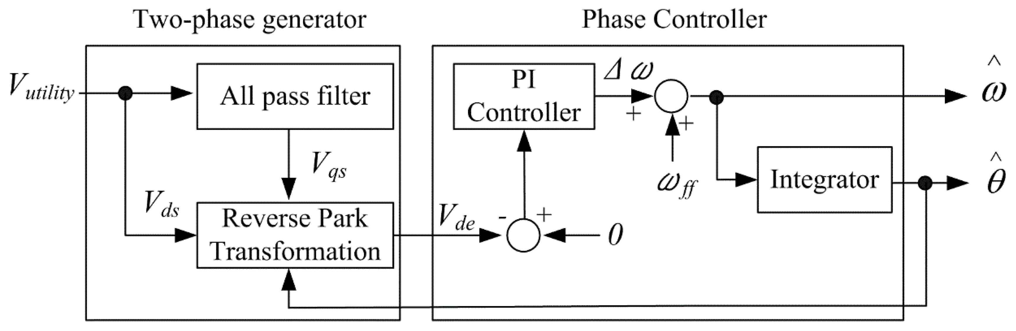
To use the reference frame theory for a simple control, the single-phase voltage should be virtual two-phase voltage that has a 90-degree out-of-phase component. Based on this concept, the PLL for a single-phase system consists of two stages: A two-phase generator and a phase controller, as shown in Figure 1.
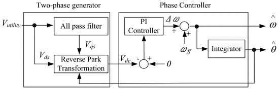
Figure 1.
Block diagram of PLL for a single-phase PV inverter controller.
2.1. Two-Phase Generator
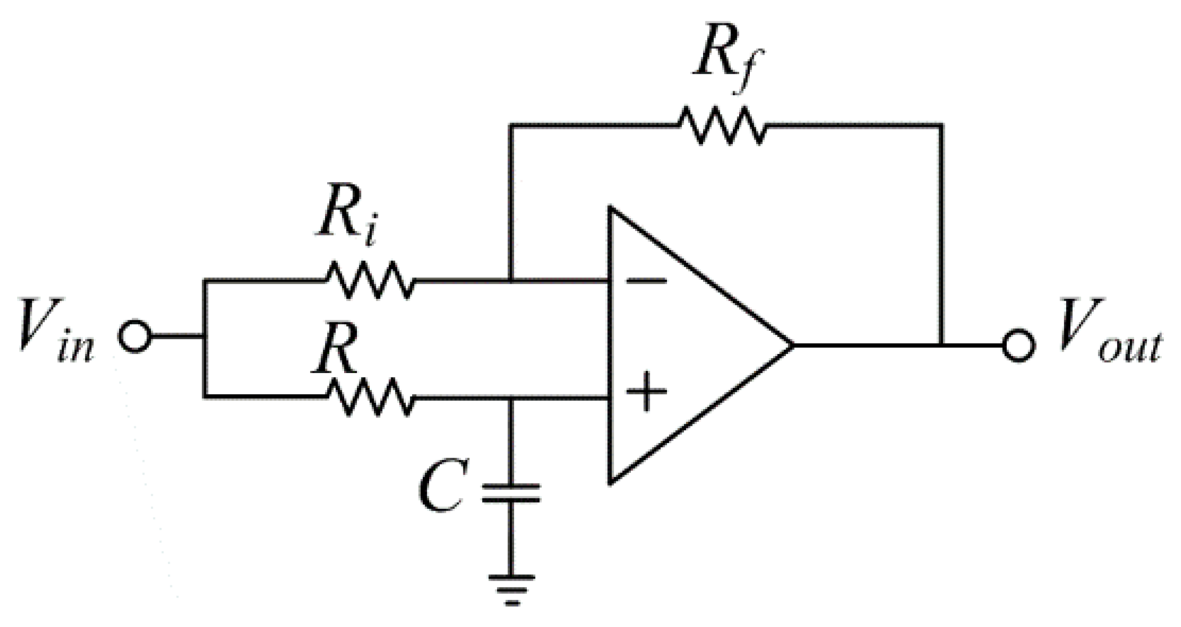
In Figure 1, Vqs is defined as a 90-degree lagging component of Vds. There are a few ways to calculate Vqs. In this paper, an all-pass filter is used to achieve the 90-degree out-of-phase component in the utility voltage, as shown in Figure 2. When the input resistance Ri is equal to the feedback resistance Rf, there is no magnitude attenuation.
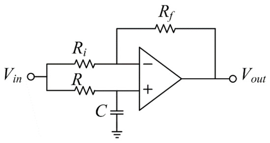
Figure 2.
Analog lagging all-pass filter topology.
The output voltage phase will be changed to the transfer function in (1), based on the input voltage.
After applying a bilinear transformation of (5) into (4), the discrete all-pass filter equation can be drawn as Equations (6) and (7).
where Ts is the sampling period
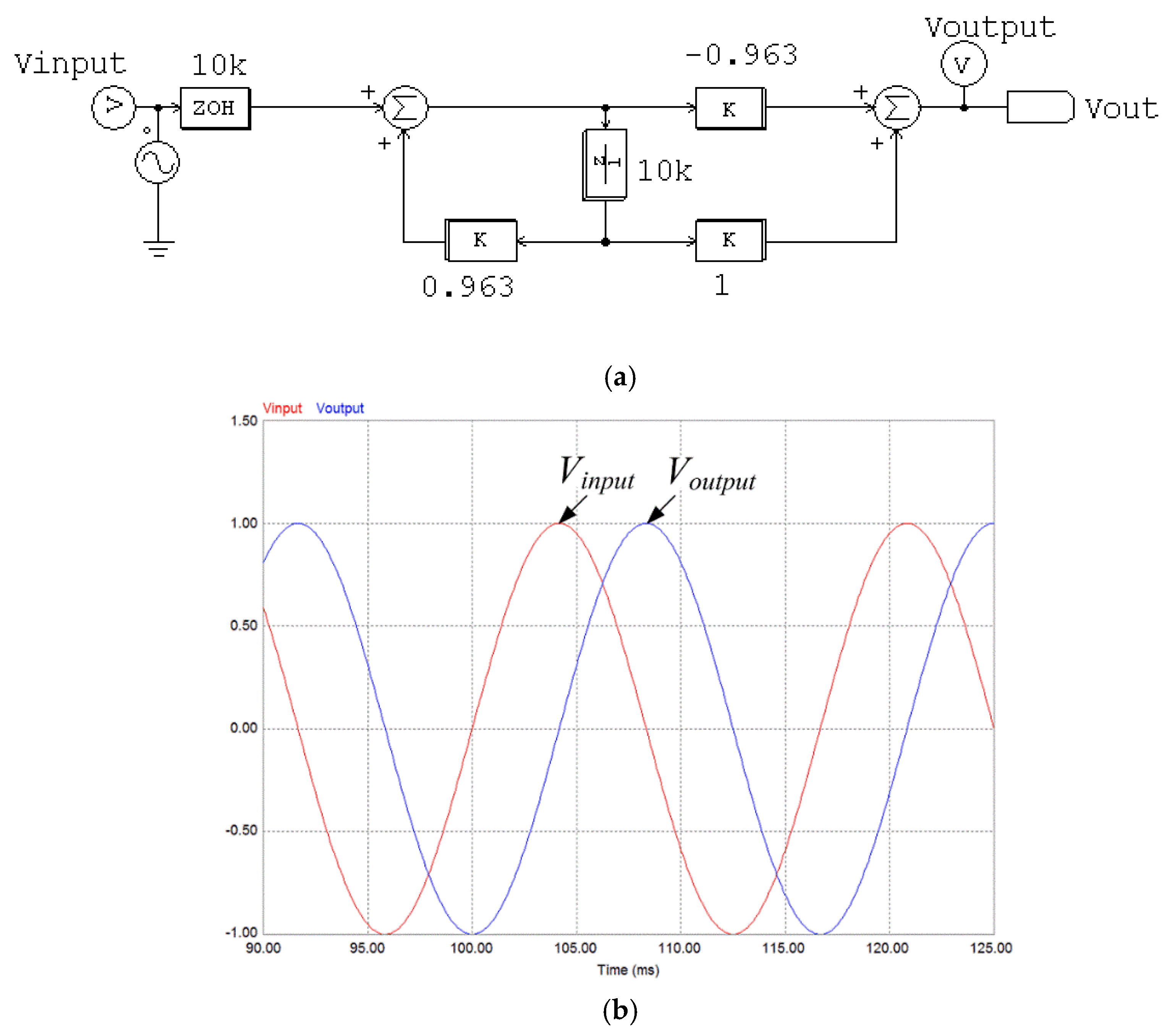
To obtain a 90-degree out-of-phase component from the input voltage, the filter resistance and capacitance should be determined by (3). If the filter resistance is 1 kΩ, then the filter capacitance will be 1.5315 μF. In that case, the β is 0.963, and it can be simulated based on (7), as shown in Figure 3. Obviously, the output signal has a 90-degree out-of-phase lag with respect to the input voltage.
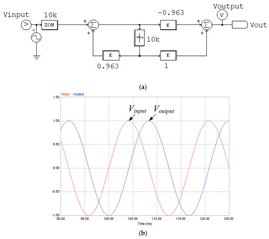
Figure 3.
Digital all-pass filter simulation results for 90-degree out-of-phase lagging.
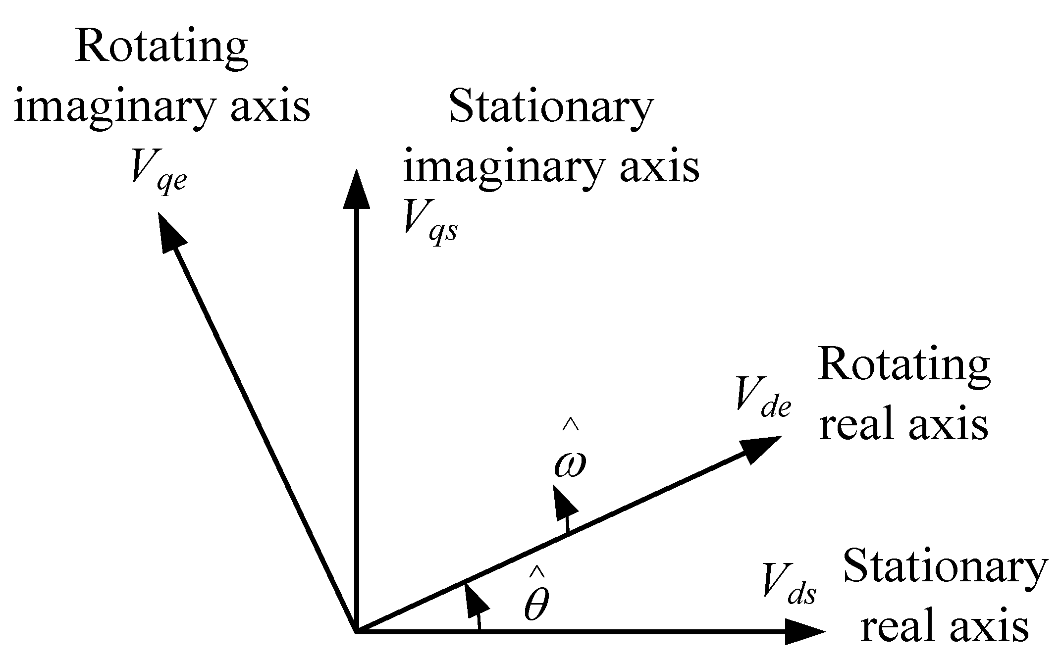
With the grid voltage Vds and the calculated 90-degree out-of-phase lagging voltage Vqs, the active and reactive component in the reference frame can be drawn by applying the reverse Park transformation as (8). In (8) and (9), the rotating reference frame is based on the estimated phase angle and the estimated frequency , as shown in Figure 4.

Figure 4.
Estimated reference frame for a single-phase system.
2.2. Phase Controller
As shown in (9), the reactive voltage component Vde should be maintained at zero for the unity power factor of the estimated phase angle to be equal to the real phase angle θ. To control the estimated phase angle error, Δω is obtained using a PI controller. Δω is added to the initial value ωff to achieve the estimated frequency and the estimated phase angle , as shown in Figure 1.
3. The Line Frequency Measurement Techniques from the Digital PLL
The accurate line frequency information from the PLL controller is very significant for the evaluation of the system’s safety status, which is required to meet national and international grid code requirements [29,30,31]. In addition, this information is used to generate the PV inverter controller command, such as the anti-islanding function and the Active Frequency Drift (AFD) method [10,11,12,14]. This section discusses both the conventional PLL technique and the proposed one to calculate the line frequency.
3.1. The Conventional Method
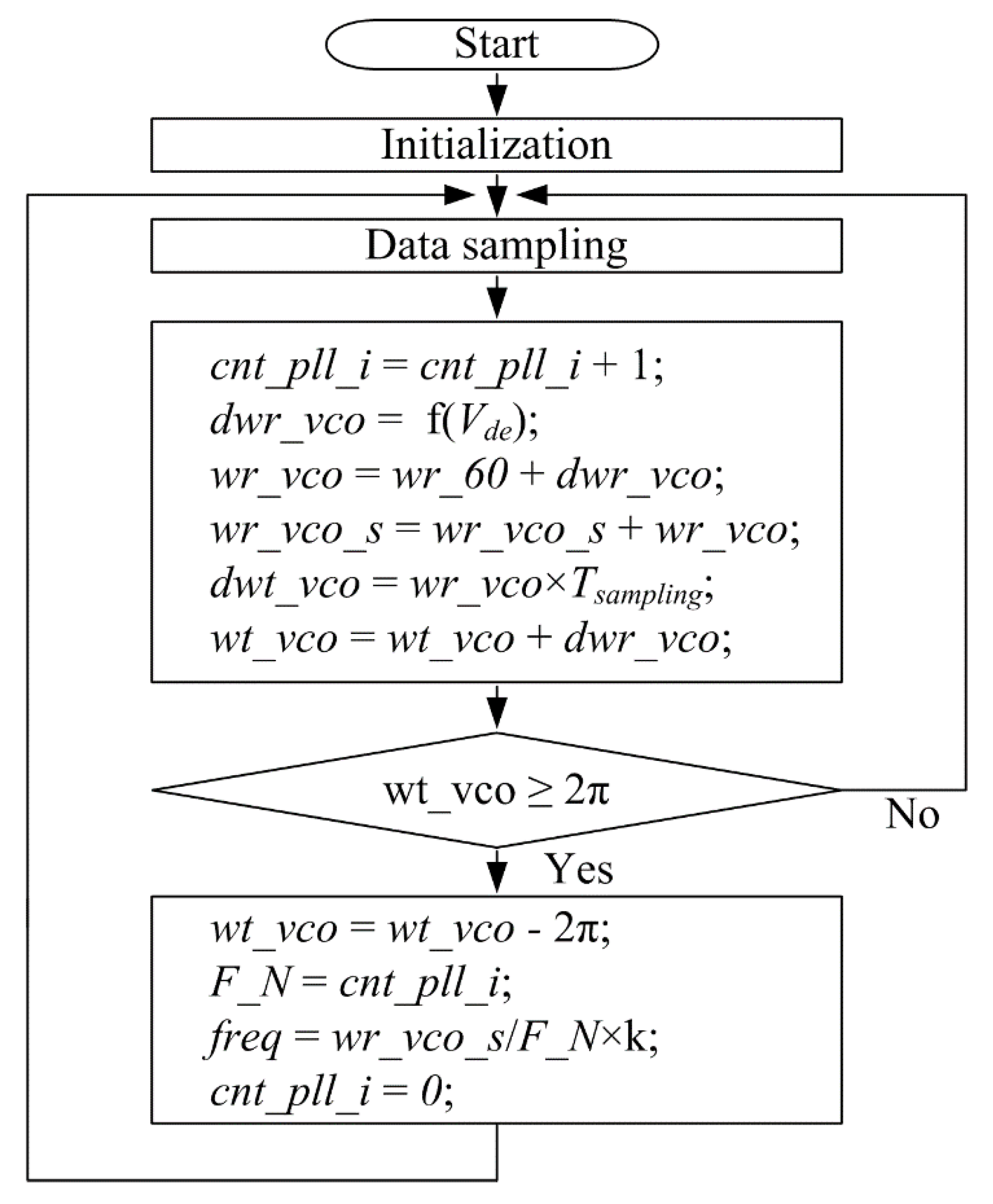
The operational principle of the conventional PLL technique to calculate the line frequency of PV inverter output voltage is shown in Figure 5. Angular frequency information (), as shown in Figure 1, is also used to calculate phase information. Based on the phase information, the line frequency is calculated by the relationship between the sampling frequency (fsampling) and the number of the counter (F_N) during a line cycle, as shown in Figure 5. After a line cycle, the phase information (wt_vco) does not match the exact one-line cycle phase 2π, because the incremental phase (dwt_vco) is not small enough. Since the sampling frequency is limited by the microcontroller performance, it is hard to increase the sampling frequency. In other words, the incremental phase is not small enough. Thus, the amount of error caused by the phase difference between wt_vco, after a line cycle, and 2π has a negative effect on the calculated line frequency measurement. Thus, the conventional PLL technique to measure the line frequency has shown low accuracy.
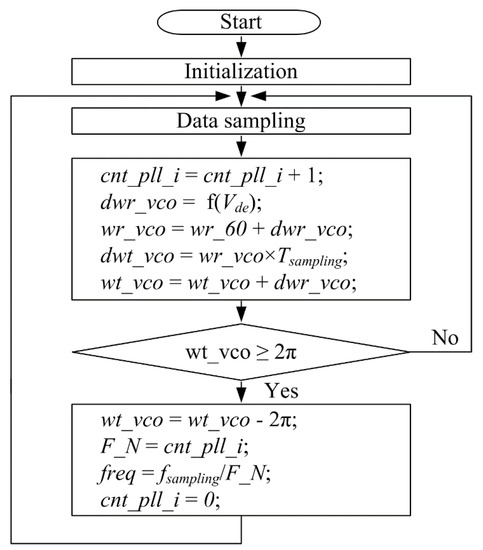
Figure 5.
Flowchart of the conventional PLL technique to calculate the line frequency.
3.2. The Proposed Method
The operational principle of the proposed PLL technique to calculate the line frequency of PV inverter output voltage is shown in Figure 6. Unlike the conventional method, this method uses the angular frequency to directly measure the frequency after every line cycle. As shown in Figure 6, by summing the angular frequency (wt_vco) during a single line cycle, the summation of angular frequency wt_vco_s can be achieved. After a line cycle, the averaged angular frequency information can be generated by dividing the number of the counter F_N for a line cycle. It could be converted to the line frequency with an appropriate scaling factor k. The scaling factor k is related to several parameters, such as the sampling frequency of the microcontroller, the nominal line frequency, etc. In this paper, the scaling factor k was easily determined by using only one example case. Unlike the conventional method, there is little relationship between the proposed method and the phase error, causing a phase difference between wt_vco and 2π. With the proposed method, the phase error only affects the number of the counter, and its impact is negligible. Therefore, the averaged angular frequency information is quite reliable for calculating the line frequency.
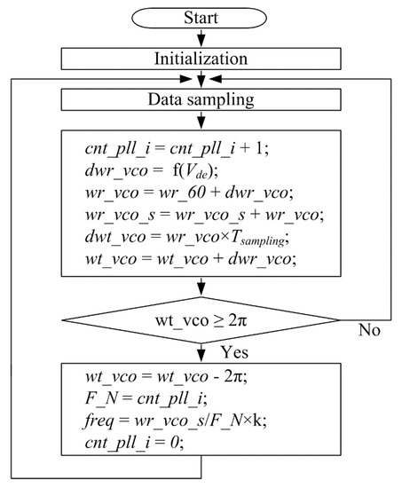
Figure 6.
Flowchart of the proposed PLL technique to calculate the line frequency.
4. Simulation Results
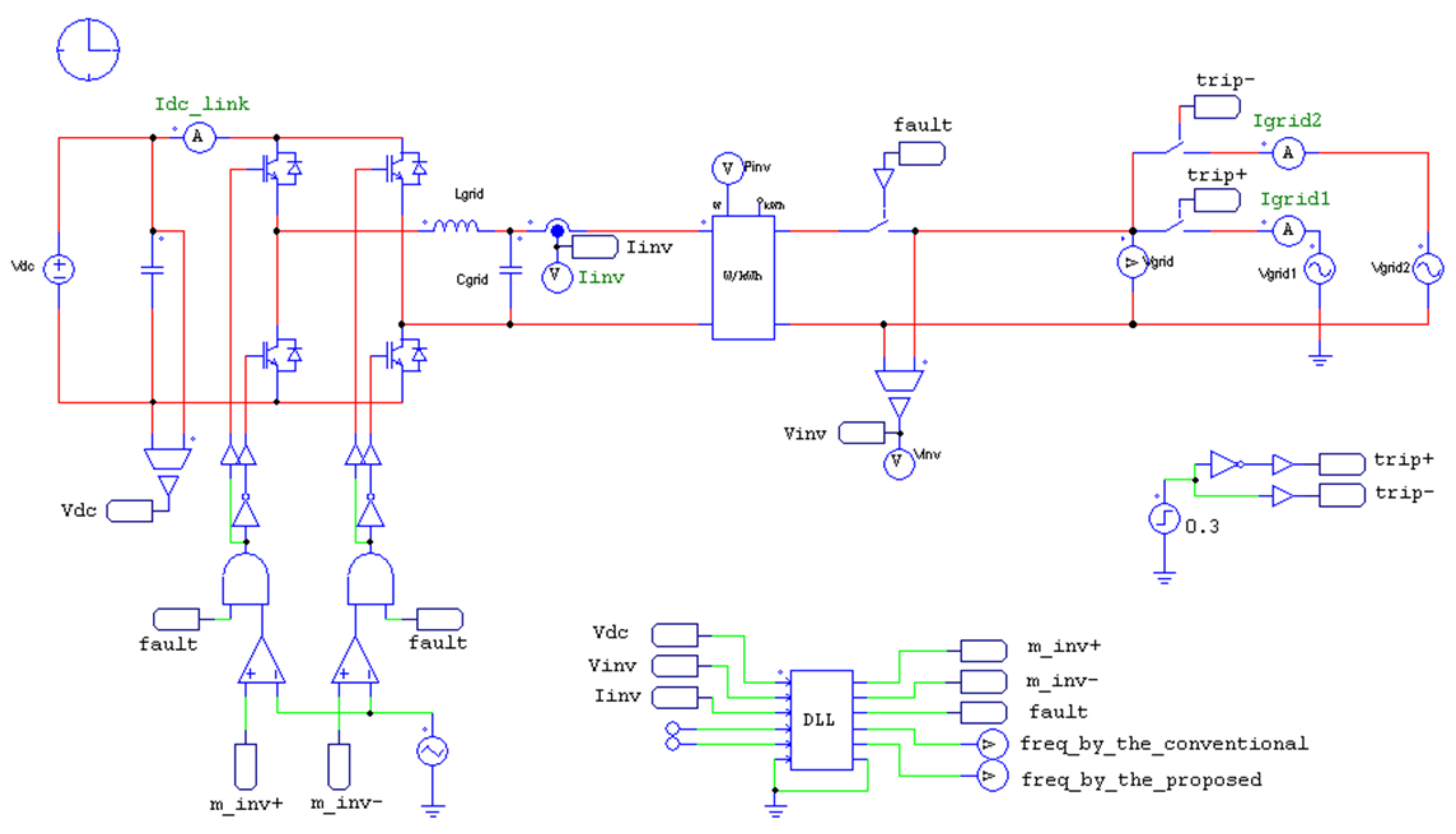
To verify the performance accuracy of the proposed PLL method, a simulation was conducted using a 350 W grid-connected PV micro-inverter application, as shown in Figure 7. Further electrical specifications of the simulation circuit are shown in Table 1. According to the related international standards, such as IEEE Std. 1547, the normal frequency range was determined to be between 59.3 Hz and 60.5 Hz [21].
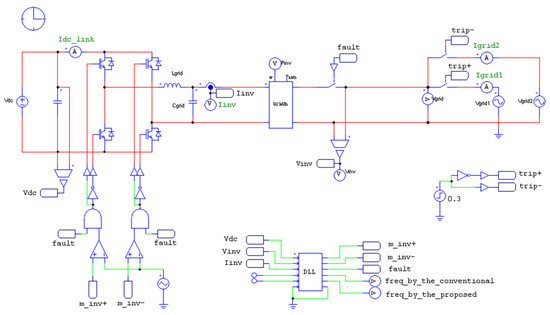
Figure 7.
Simulation circuit of a single-phase PV micro-inverter for evaluating the grid-connection.

Table 1.
Electrical specification of the simulation circuit.
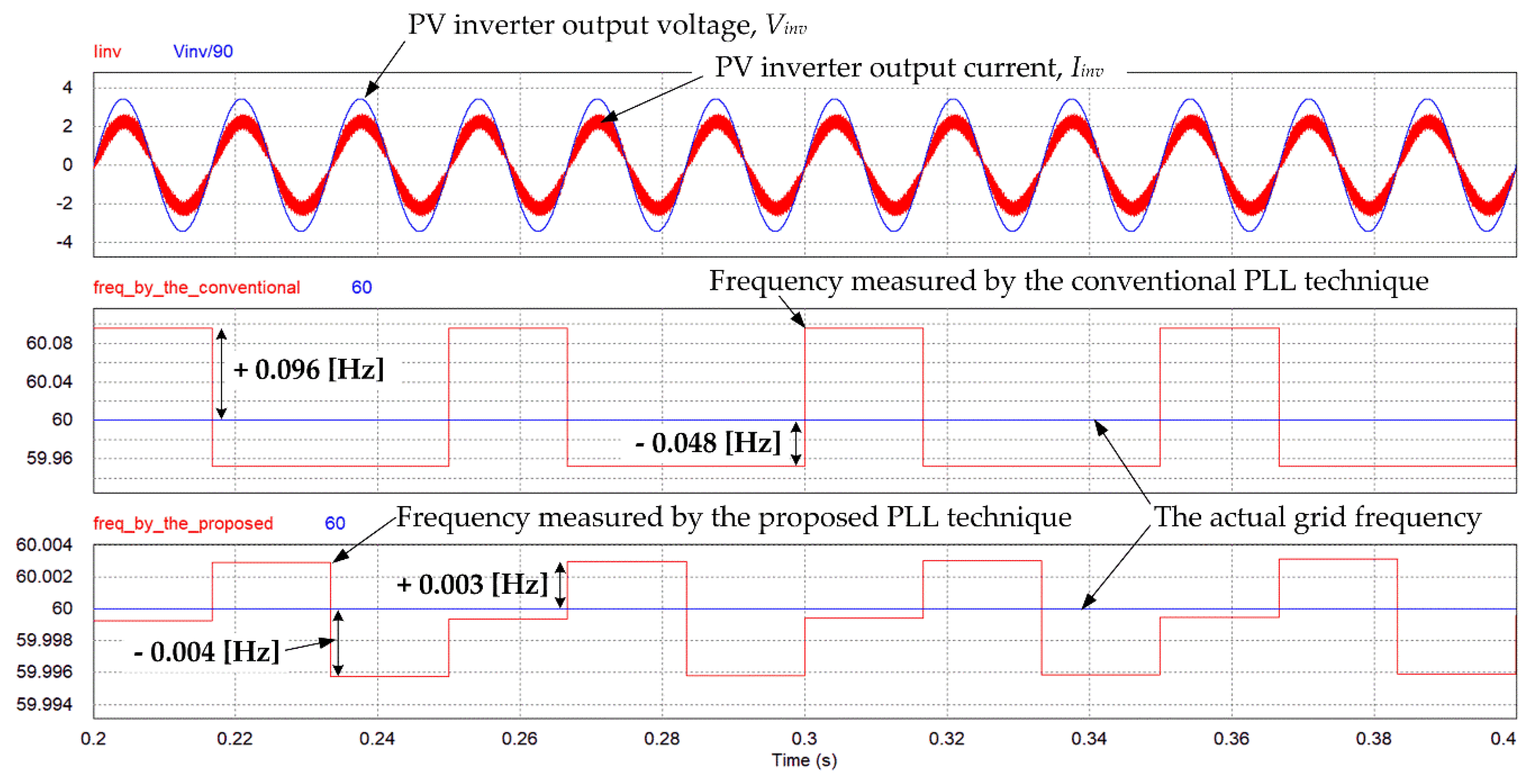
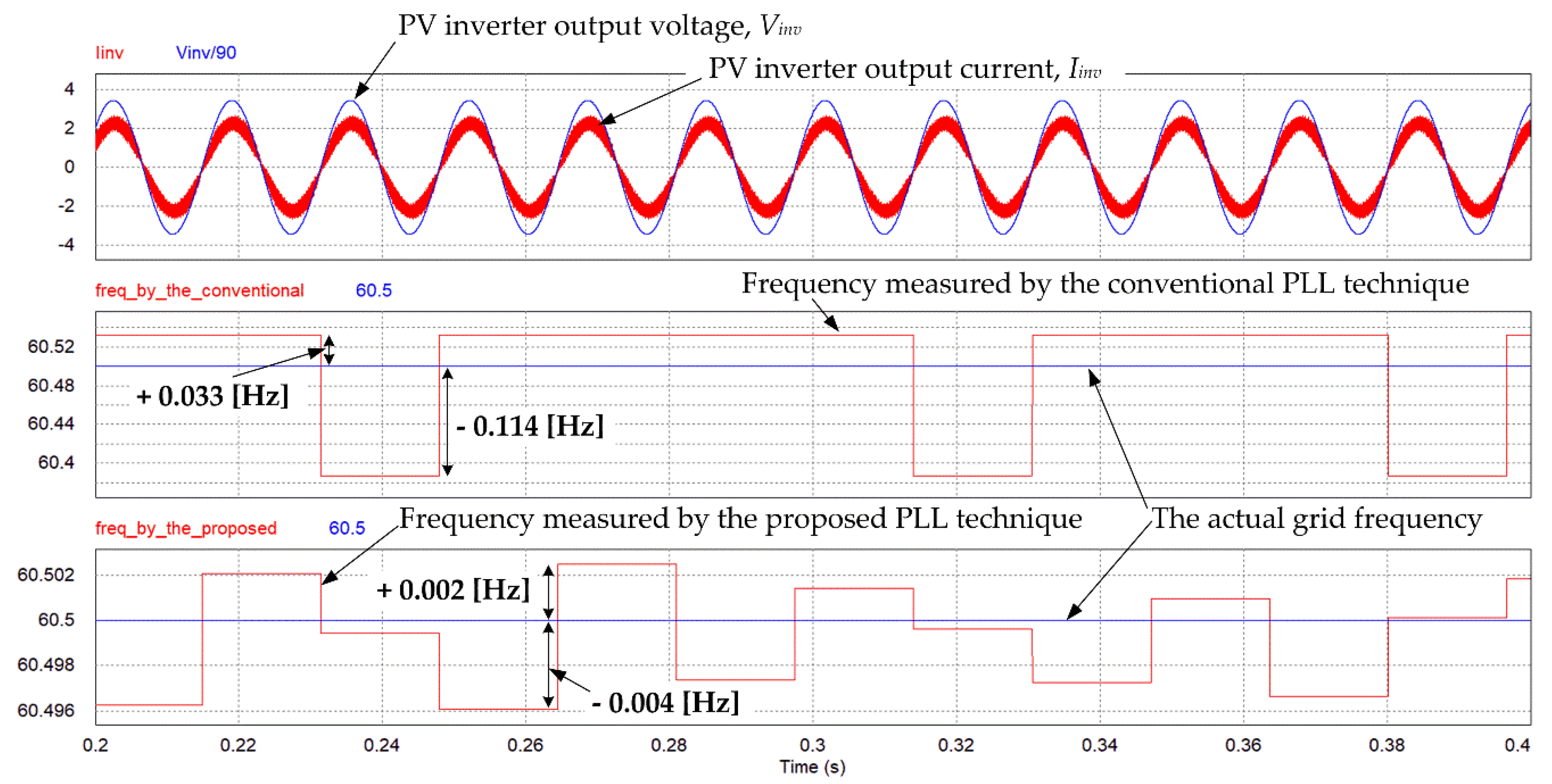
First, the steady-state responses were discussed. Throughout the normal frequency range, measured line frequency information was obtained using both the conventional PLL technique and the proposed one, shown in Figure 8, Figure 9, Figure 10, Figure 11 and Figure 12. In these figures, the actual frequency means the frequency command of the grid voltage Vgrid, as shown in Figure 7. As shown in Figure 8, when the grid voltage source is operated at 60 Hz, the PV inverter output current is maintained in phase with the PV inverter output voltage. The line frequencies are measured by two different PLL techniques, as shown in Figure 8. While the measurement error of the line frequency using the conventional method changes from −0.048 Hz to +0.096 Hz, the measurement error of the line frequency using the proposed method varies from –0.004 Hz to +0.003 Hz. Obviously, the proposed method shows a measurement error at least 10 times smaller than that of the conventional method. Similarly, the measured line frequencies, when the grid frequencies are 60.5 Hz and 59.3 Hz, are shown in Figure 9 and Figure 10. According to the results shown in Figure 9 and Figure 10, the proposed method shows higher accuracies than the conventional one. The quantitative analysis of the accuracy of both PLL techniques is summarized in Table 2. Using the proposed method, the measurement error is around 80 times lower that using the conventional one.
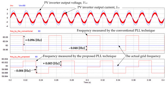
Figure 8.
Key waveforms of the PV inverter when the grid voltage frequency is 60 Hz.
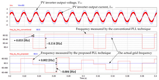
Figure 9.
Key waveforms of the PV inverter when the grid voltage frequency is 60.5 Hz.
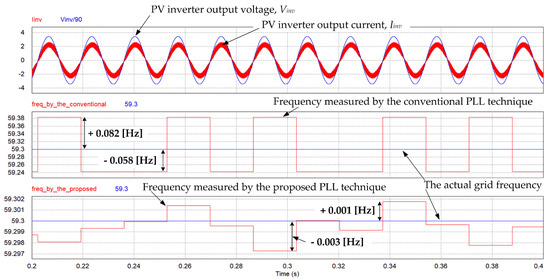
Figure 10.
Key waveforms of the PV inverter when the grid voltage frequency is 59.3 Hz.

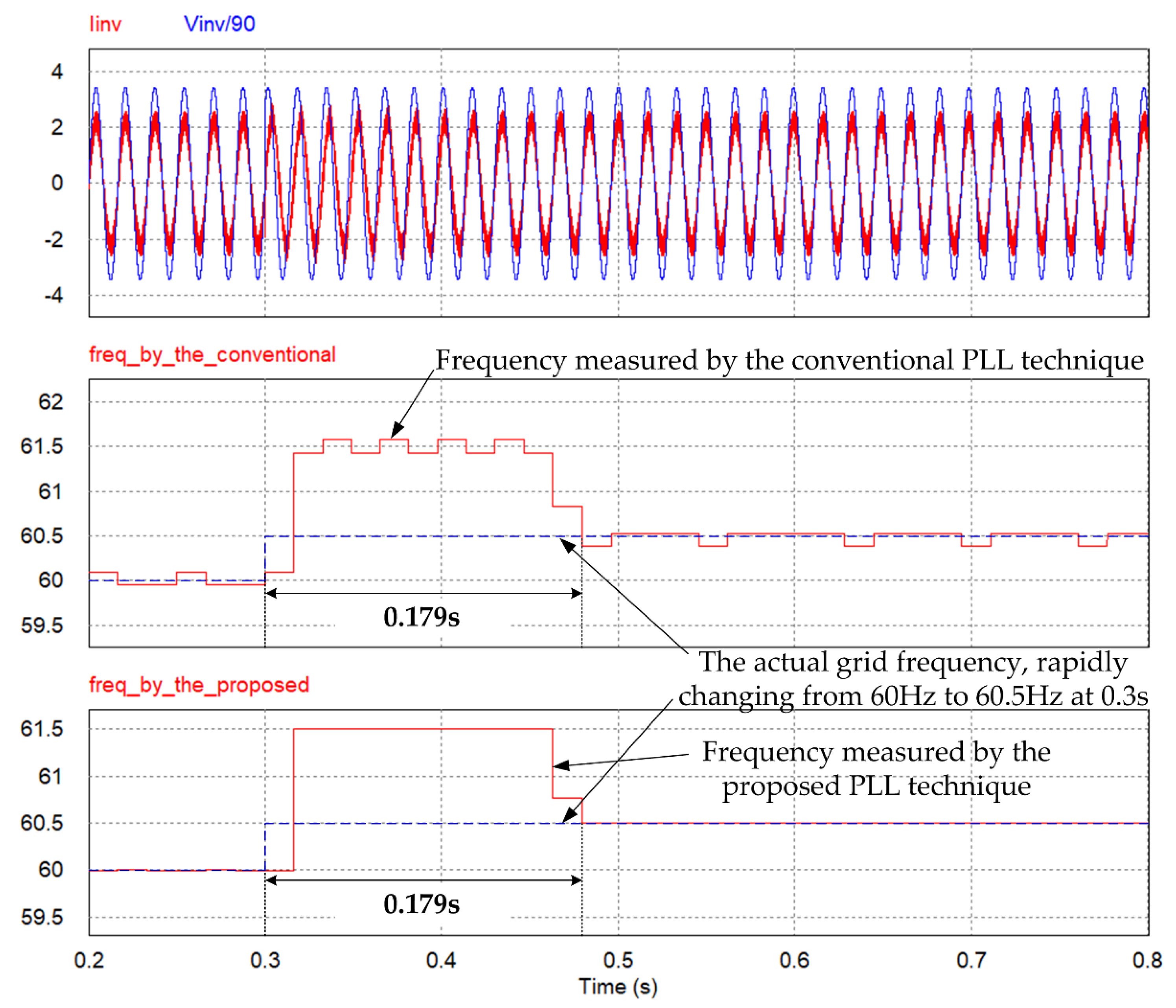
Figure 11.
Key waveforms of the PV inverter when the grid voltage frequency is rapidly changing from 60 Hz to 60.5 Hz.
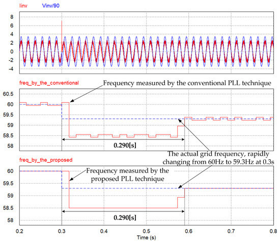
Figure 12.
Key waveforms of the PV inverter when the grid voltage frequency is rapidly changing from 60 Hz to 59.3 Hz.
Table 2.
Measurement error using two different PLL techniques.
Secondly, the transient responses using both PLL techniques were analyzed when the grid voltage frequency was changing dramatically. It was assumed that the grid voltage frequency was changing from the nominal frequency 60 Hz to two other states, 60.5 Hz and 59.3 Hz. This condition can be implemented by changing the frequency command of the grid voltage Vgrid at 0.3 s, as shown in Figure 8. The key waveforms of the PV inverter, when the grid voltage frequency is changing rapidly from 60 Hz to 60.5 Hz at 0.3 s, are shown in Figure 11. Both methods have the same transient time of 0.179 s. Similarly, both methods have the same transient time of 0.290 s when the grid voltage frequency is changing rapidly from 60 Hz to 59.3 Hz at 0.3 s, as shown in Figure 12. This is because both methods have the same sampling counter for detecting a line cycle.
According to the simulation results, it can be stated that the proposed PLL technique has a higher accuracy than the conventional one and the same transient response time.
5. Conclusions
In this paper, a novel frequency measurement method for the digital PLL control structure for single phase grid-connected PV applications is presented. While the conventional PLL controller uses phase information to calculate the frequency of PV inverter output voltage after every line cycle, this paper uses the angular frequency to directly measure the frequency after every line cycle. Thus, the measured frequency of the proposed method is more accurate than that of the conventional one. According to the corresponding simulation, measuring the line frequency, the measurement error of the proposed method is around 80 times less than that of the conventional one. By using the proposed PLL technique, a more accurate line frequency can be achieved, and a more accurate control command, such as the anti-islanding function and over/under frequency protection, can be generated.
Funding
This work was supported by the National Research Foundation of Korea (NRF) grant funded by the Korea government (MSIP) (grant number 2016R1C1B1007001).
Conflicts of Interest
The author declares no conflict of interest.
References
- Kurtz, S.; Sample, T.; Wohlgemuth, J.; Zhou, W.; Bosco, N.; Althaus, J.; Philips, N.; Deceglie, M.; Flueckiger, C.; Hacke, P.; et al. Moving toward quantifying reliability—The next step in a rapidly maturing PV industry. In Proceedings of the 2015 IEEE 42nd Photovoltaic Specialist Conference, New Orleans, LA, USA, 14–19 June 2015; pp. 1–8. [Google Scholar]
- Jaber, A.; Abu, Q.; Jiang, Y. Distributed photovoltaic solar system architecture with single-power inductor single-power converter and single-sensor single maximum power point tracking controller. IET Power Electron. 2014, 7, 2600–2609. [Google Scholar]
- Blaabjerg, F.; Consoli, A.; Ferreira, J.A.; Wyk, J.D. The future of electronic power processing and conversion. IEEE Trans. Power Electron. 2005, 20, 715–720. [Google Scholar] [CrossRef]
- Chung, S.K. A phase tracking system for three phase utility interface inverters. IEEE Trans. Power Electron. 2000, 15, 431–438. [Google Scholar] [CrossRef]
- Hadjidemetriou, L.; Kyriakides, E.; Blaabjerg, F. A robust synchronization to enhance the power quality of renewable energy systems. IEEE Trans. Ind. Electron. 2015, 62, 4858–4868. [Google Scholar] [CrossRef]
- Golestan, S.; Guerrero, J.M.; Vasquez, J.C. Single-phase PLLs: A review of recent advances. IEEE Trans. Power Electron. 2017, 32, 9013–9030. [Google Scholar] [CrossRef]
- Xun, P.; Zhu, P.; Zhang, Z.; Cui, P.; Xiong, Y. Detectors on edge nodes against false data injection on transmission lines of smart grid. Electronics 2018, 7, 89. [Google Scholar] [CrossRef]
- Capizzi, G.; Tina, G. Long-term operation optimization of integrated generation systems by fuzzy logic-based management. Energy 2007, 32, 1047–1054. [Google Scholar] [CrossRef]
- Bonanno, F.; Gapizzi, G.; Sciuto, G.L. A neuro wavelet-based approach for short-term load forecasting in integrated generation systems. In Proceedings of the 2013 International Conference on Clean Electrical Power (ICCEP), Alghero, Italy, 11–13 June 2018; pp. 772–776. [Google Scholar]
- Ropp, M.E.; Begovic, M.; Rohatgi, A. Analysis and performance assessment of the active frequency drift method of islanding prevention. IEEE Trans. Energy Convers. 1999, 14, 810–816. [Google Scholar] [CrossRef]
- Hung, G.K.; Chang, C.C.; Chen, C.L. Automatic phase-shift method for islanding detection of grid-connected photovoltaic inverters. IEEE Trans. Energy Convers. 2003, 18, 169–173. [Google Scholar] [CrossRef]
- Liu, F.; Zhang, Y.; Xue, M.; Lin, X.; Kang, Y. Investigation and evaluation of active frequency drifting methods in multiple grid-connected inverters. IET Power Electron. 2012, 5, 485–492. [Google Scholar] [CrossRef]
- Vieira, J.C.; Freitas, W.; Xu, W.; Morelato, A. Performance of frequency relays for distributed generation protection. IEEE Trans. Power Deliv. 2006, 21, 1120–1127. [Google Scholar] [CrossRef]
- Lopes, L.A.C.; Zhang, Y. Islanding detection assessment of multi-inverter systems with active frequency drifting methods. IEEE Trans. Power Deliv. 2008, 23, 480–486. [Google Scholar] [CrossRef]
- Velasco, D.; Trujillo, C.L.; Narvaez, E.A. Review of anti-islanding methods: Analysis by figures of merit tools for controllers reconfiguration in microgrids. IEEE Lat. Am. Trans. 2015, 13, 679–686. [Google Scholar] [CrossRef]
- Thacker, T.; Boroyevich, D.; Burgos, R.; Wang, F. Phase-locked loop noise reduction via phase detector implementation for single phase systems. IEEE Trans. Ind. Electron. 2011, 58, 2482–2490. [Google Scholar] [CrossRef]
- Golesatan, S.; Guerrero, J.M.; Vasquez, J.C. A PLL-based controller for three-phase grid-connected power converters. IEEE Trans. Power Electron. 2018, 33, 911–916. [Google Scholar] [CrossRef]
- Chung, S.K. Phase-locked loop for grid-connected three-phase power conversion systems. IEE Proc.—Electr. Power Appl. 2000, 147, 213–219. [Google Scholar] [CrossRef]
- Pahlevani, M.; Jain, P. A fast DC-bus voltage controller for bidirectional single-phase AC/DC converters. IEEE Trans. Power Electron. 2015, 30, 4536–4547. [Google Scholar] [CrossRef]
- Liu, Y.C.; Chen, M.C.; Yang, C.Y.; Kim, K.A.; Chiu, H.J. High-efficiency isolated photovoltaic microinverter using wide-band gap switches for standalone and grid-tied applications. Energies 2018, 11, 569. [Google Scholar] [CrossRef]
- Dong, D.; Wen, B.; Boroyevich, D.; Mattavelli, P.; Xue, Y. Analysis of phase-locked loop low-frequency stability in three-phase grid-connected power converters considering impedance interactions. IEEE Trans. Ind. Electron. 2015, 62, 310–321. [Google Scholar] [CrossRef]
- Golestan, S.; Guerrero, J.M.; Abusorrah, A.; Al-Hindawi, M.; Al-Turki, Y. An adaptive quadrature singal generation-based single-phase phase-locked loop for grid-connected applications. IEEE Trans. Ind. Electron. 2017, 64, 2848–2854. [Google Scholar] [CrossRef]
- Yu, B.; Matsui, M.; Yu, G. A correlation-based islanding-detection method using current-magnitude disturbance for PV system. IEEE Trans. Ind. Electron. 2011, 58, 2935–2943. [Google Scholar] [CrossRef]
- Zhang, Q.; Sung, X.D.; Zhong, Y.R.; Matsui, M.; Ren, B.Y. Analysis and design of a digital phase-locked loop for single-phase grid-connected power conversion systems. IEEE Trans. Ind. Electron. 2011, 58, 3581–3592. [Google Scholar] [CrossRef]
- Geng, H.; Xu, D.; Wu, B. A novel hardware-based all-digital phase-locked loop applied to grid-connected power converters. IEEE Trans. Ind. Electron. 2011, 58, 1737–1745. [Google Scholar] [CrossRef]
- Yu, B. An improved active frequency drift anti-islanding method for multiple PV micro-inverter systems. IEICE Electron. Express 2014, 11, 1–11. [Google Scholar] [CrossRef]
- Golestan, S.; Ramezani, M.; Guerrero, J.M.; Freijedo, F.D.; Monfared, M. Moving average filter based phase-locked loops: Performance analysis and design guidelines. IEEE Trans. Power Electron. 2014, 29, 2750–2763. [Google Scholar] [CrossRef]
- Lu, C.; Zhou, Z.; Jiang, A.; Luo, M.; Shen, P.; Han, Y. Comparative performance evaluation of phase locked loop (PLL) algorithms for single-phase grid-connected converters. In Proceedings of the 2016 IEEE 8th International Power Electronics and Motion Control Conference (IPEMC-ECCE Asia), Hefei, China, 22–25 May 2016; pp. 902–907. [Google Scholar]
- IEEE Standard Conformance Test Procedures for Equipment Interconnecting Distributed Resources with Electric Power Systems; IEEE Std.1547.1-2005; IEEE Standard Association: Piscataway, NJ, USA, 2005.
- Photovoltaic (PV) Systems—Characteristics of the Utility Interface; IEC Standard IEC 61727:2004; IEC Webstore; IEC: Geneva, Switzerland, 2004.
- Test Procedure of Islanding Prevention Measures for Utility-Interconnected Photovoltaic Inverters; IEC Standard IEC 62116: 2014; IEC Webstore; IEC: Geneva, Switzerland, 2014.


© 2018 by the author. Licensee MDPI, Basel, Switzerland. This article is an open access article distributed under the terms and conditions of the Creative Commons Attribution (CC BY) license (http://creativecommons.org/licenses/by/4.0/).