Article

An Effective Switching Algorithm for Single Phase Matrix Converter in Induction Heating Applications

by
Anand Kumar
1,*,
Pradip Kumar Sadhu
1,
Dusmanta Kumar Mohanta
2 and
Maddikara Jaya Bharata Reddy
3
1
Department of Electrical Engineering, Indian Institute of Technology, Indian School of Mines, Dhanbad 826004, India
2
Department of Electrical and Electronics Engineering, Birla Institute of Technology, Mesra, Ranchi 835215, India
3
Department of Electrical and Electronics Engineering, National Institute of Technology, Trichy 620015, India
*
Author to whom correspondence should be addressed.
Electronics 2018, 7(8), 149; https://doi.org/10.3390/electronics7080149
Submission received: 26 June 2018 / Revised: 8 August 2018 / Accepted: 16 August 2018 / Published: 18 August 2018

Abstract

:
Prevalent converters for induction heating (IH) applications employ two-stage conversion for generating high-frequency magnetic field, namely, AC to DC and then DC to high-frequency AC (HFAC). This research embarks upon a direct conversion of utility AC to high frequency AC with the design of a single-phase matrix converter (SPMC) as a resonant converter using a modified switching technique for IH application. The efficacy of the proposed approach is validated through different attributes such as unity power factor, sinusoidal input current and low total harmonic distortion (THD). The developed prototype-embedded system has high pragmatic deployment potential owing to its cost effectiveness using Arduino mega 2560 and high voltage/current as well as low switching time IXRH40N120 insulated-gate bipolar transistor (IGBT). Different results of the prototype-embedded system for IH application have been verified using Matlab Simulink environment to corroborate its efficacy.

1. Introduction

The recent trend shows that the industrial as well as domestic induction heating (IH) has become extremely popular because of its unique advantages such as higher efficiency, reduced heating time and environmental friendliness. To implement the IH for different appliances, a high-frequency (HF) alternating electromotive force (e.m.f.) is required that typically lies between 20 KHz to 100 KHz depending on the type of applications such as brazing, melting processes and for domestic cooking [1,2,3,4]. In the last few decades, various new topologies of HF resonant inverter have been proposed to generate H.F alternating e.m.f. [5]. However, ongoing research and development are entering into a new phase ensuring cost-effectiveness [6,7], increased cooling capabilities [8] and high efficiency [9,10] within the field of electrical power conversion and process.
The conventional IH system follows two stages: (a) rectification [11,12] and (b) HF resonant inverter operation [13,14,15]. In the first stage, DC power is obtained using a full bridge diode rectifier. After rectification, a small value of inductor and capacitor is connected to obtain DC with ripple content ensuring unity input power factor [12]. This high ripple DC link voltage acts as a power supply for the HF resonant inverter (Figure 1a). This is also an indirect method for the conversion of supply/grid frequency to HFAC.
Various topologies of HF resonant inverters have been developed such as the half-bridge series resonant inverter (HB-SRI) [16], full bridge series resonant inverter (FB-SRI) [17], single switch topology [18] etc. Although, these converters have been designed using insulated-gate bipolar transistor (IGBT) because of its higher current/voltage handling capability, reduced control complexity and less cost. In addition, IGBTs should have low reverse recovery time and high switching frequency. It can be seen that owing to different stages in the conventional IH system, its efficiency is automatically reduced. Moreover, indirect method of conversion uses reactive energy storage elements. Thus, this method makes the converter bulky and unnecessary losses occur across the diode. Additionally, two-stage conversion of AC to HFAC conversion increases the number of components used along with complex control algorithms (such as Phase Locked Loop (PLL), Proportional Integral Derivative (PID) and Fuzzy logic controller) for obtaining high power factor, low total harmonic distortion (THD) at the input side and good power quality [19,20]. Overall, these existing topologies increase the cost as well as complexity of the controller.
Because of some preceding demerits, the popularity of an indirect method started decreasing and therefore, researchers started focussing on a direct method of AC conversion [21]. However, a lot of work has been done in this field and has been widely used in several applications [22,23]. By employing direct AC–AC converters, reductions in both component count, as well as intermediate DC link reactive element, have been accomplished [24,25]. Matrix converters, Cycloconverter and AC voltage controllers are examples of direct AC–AC conversion. Recent research shows that with the evolution of these direct AC–AC converters and their various advanced control techniques, it is possible to avail it in many applications such as traction system, industrial as well as domestic IH. The matrix converters are newly advanced converters (AC–AC) that enables high power density and eliminates DC link components with improved operational life [26].
Currently, direct AC–AC conversion is being applied for IH applications [27,28,29]. All these converters use HB–SRI, which relies on four-quadrant equivalent switching devices that are combination of two anti-series IGBTs. In [30], a SiC based AC to AC converter for domestic IH has been proposed, which uses solely four switches and only single stage energy conversion has been achieved. Moreover, single-phase matrix converter (SPMC) (which is the part of Matrix Converter) may also be used for IH applications [31]. Numerous studies have been done related to SPMC and its switching algorithm but because of its complicacy, less use of SPMC has been seen for IH application till date [21,32]. However, some authors have proposed a suitable switching algorithm ensuring unity power factor, commutation strategy and low THD for SPMC in IH applications [33,34]. But these switching algorithms seem too complicated. Therefore, in this article, to enhance potency and eliminate DC link components, a SPMC (direct AC–AC converter) is proposed using modified technique to make it appropriate for IH applications (Figure 1b). This modified switching algorithm/technique requires only two pulse width modulation (PWM) signal to operate SPMC as a frequency changer or as resonant converter for IH applications and these pulses has been generated through embedded system. Due to requirement of less number of PWM signals, the overall cost and complexity of the controller reduces.
The major contribution of this research is to develop an effective switching pattern such that SPMC works as a resonant converter and hence, can be applied for IH applications. In pursuance of this goal, switching frequency is kept higher than the resonant frequency so as to ensure zero voltage switching (ZVS). The high power factor, sinusoidal input current and low THD have been major achievements for improving its efficacy considerably. The proposed prototype system is in full agreement with recent developments in embedded technology Arduino mega 2560 and high voltage/current as well as low switching time IXRH40N120 IGBT (Appendix A, IXYS Corporation, Santa Clara, CA, USA). Another unique feature of the proposed technique based on embedded system is that it utilizes a single stage conversion of 50–60 Hz AC power to HFAC directly (i.e., as a frequency changer) without any intermediate DC link element using proposed switching algorithm and it has been congruous with simulated results. Using this technique, a higher frequency can be generated to meet the criteria of IH system.
The rest of the article is divided into five sections. In Section 2, the modified switching algorithm for SPMC as a resonant converter for IH application is extensively explained. Simulation results using modified switching algorithm for SPMC as a resonant converter for IH application has been done in MATLAB Simulink environment and is presented in Section 3 for validation. Finally, the hardware/experimental results have been shown in Section 4 which validates the simulation results and the main conclusion of the proposed article is given in Section 5.

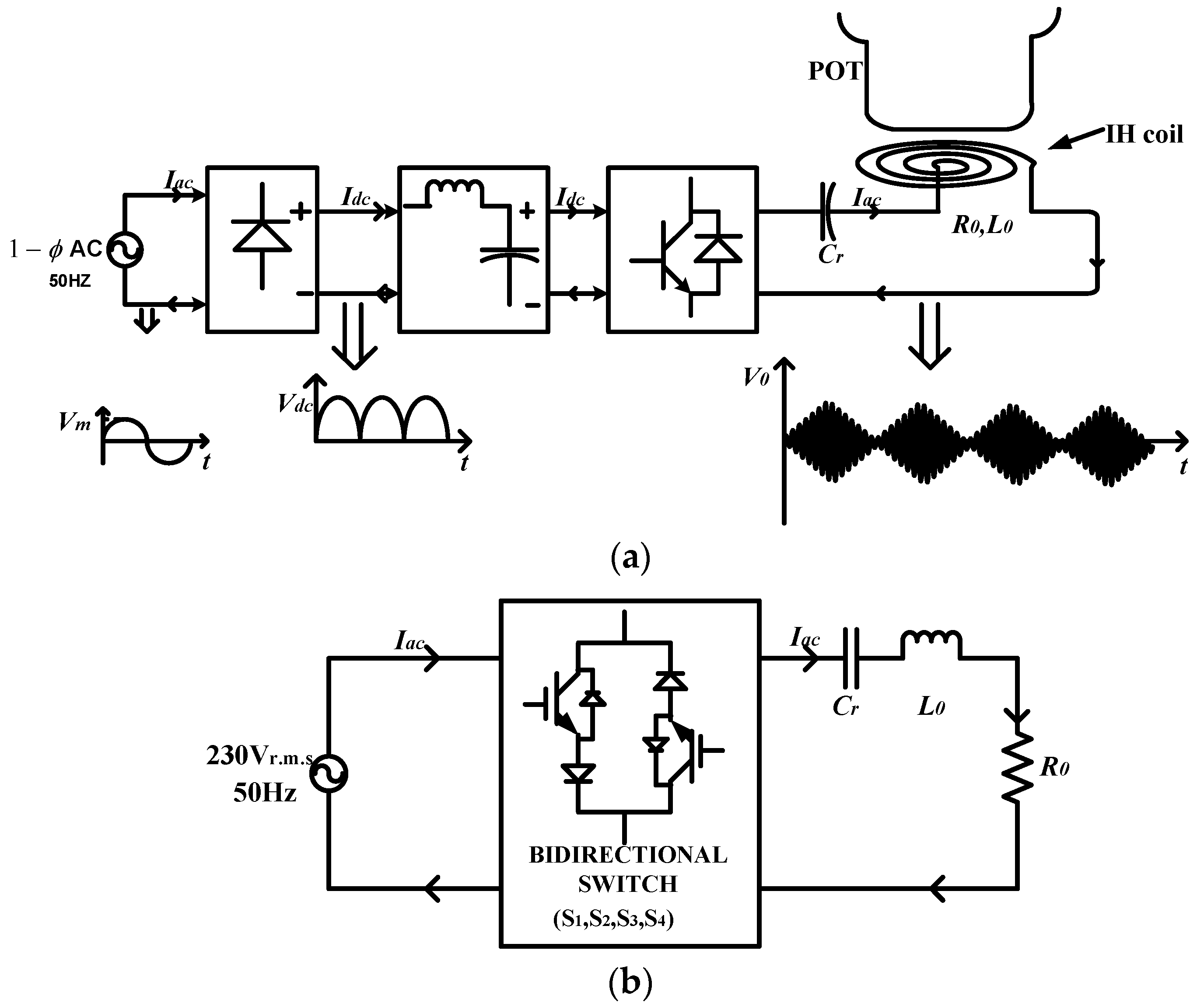
2. Single-Phase Matrix Converter and Its Modified Switching Technique for Induction Heating (IH) Applications

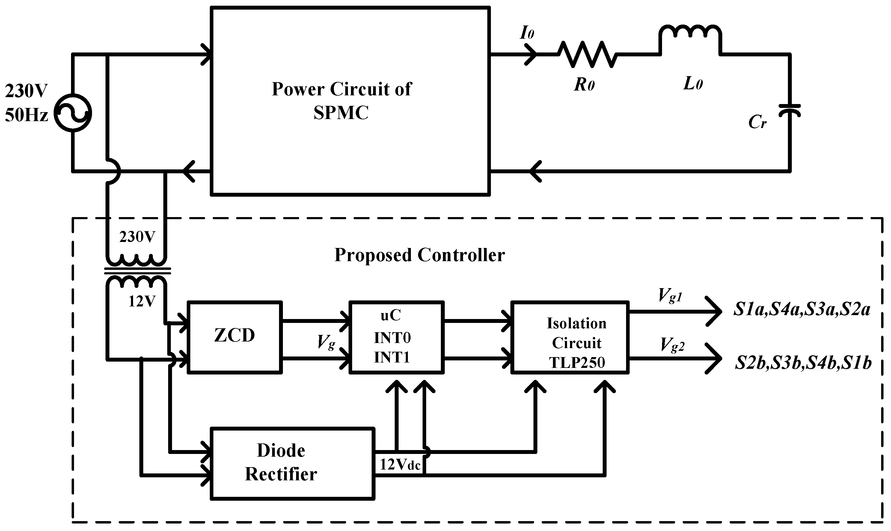
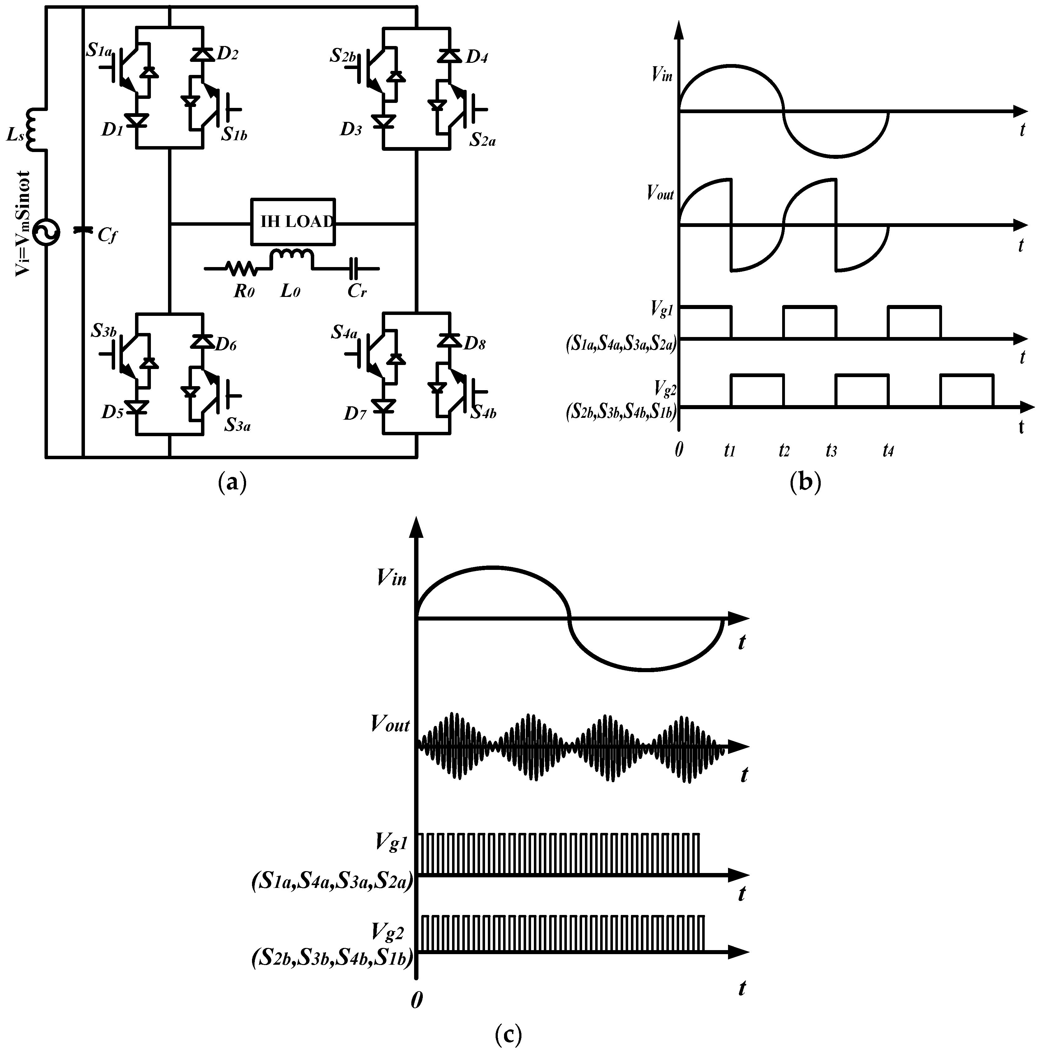
2.1. Single-Phase Matrix Converter (SPMC)

In this presented work, modified switching technique has been developed for SPMC topology to generate high frequency directly from grid/supply frequency. SPMC topology was first invented by Zuckerberger in 1997. It consists of a matrix of input and output lines with four bidirectional switches which connect the 1-ø input to 1-ø output (Figure 2a,b). Each bidirectional switch has the capability of conducting current as well as blocking voltage of both polarities simultaneously depending on the control signal. Generally, common emitter configuration is used for making bi-directional switches for SPMC. It is also referred to as 2 × 2 order matrix converter. Actually, SPMC can be operated in many types of converters such as controlled rectifier (AC–DC), inverter (DC–AC), a boost converter (DC–DC) and as a cycloconverter (AC–AC) [35]. However, in this article, only SPMC as a frequency changer or as resonant converter is discussed, which is appropriate for the IH applications. This section discusses how input frequency can be synthesized with the help of this SPMC configuration using modified switching technique and makes it essential for IH applications.

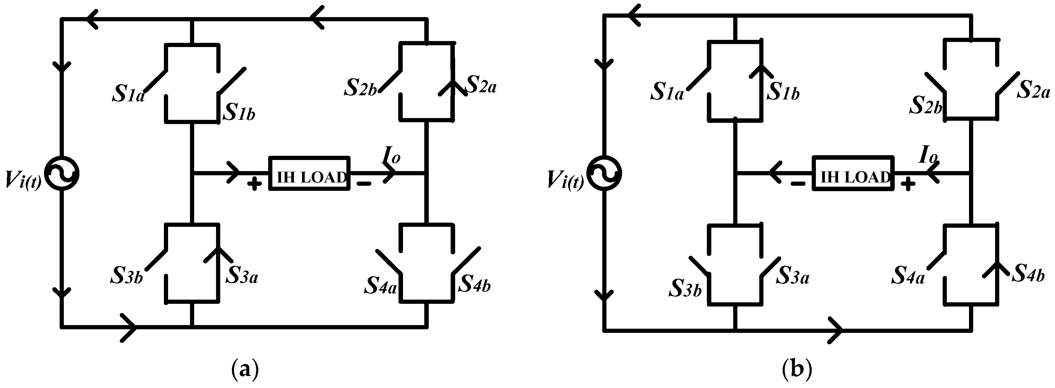
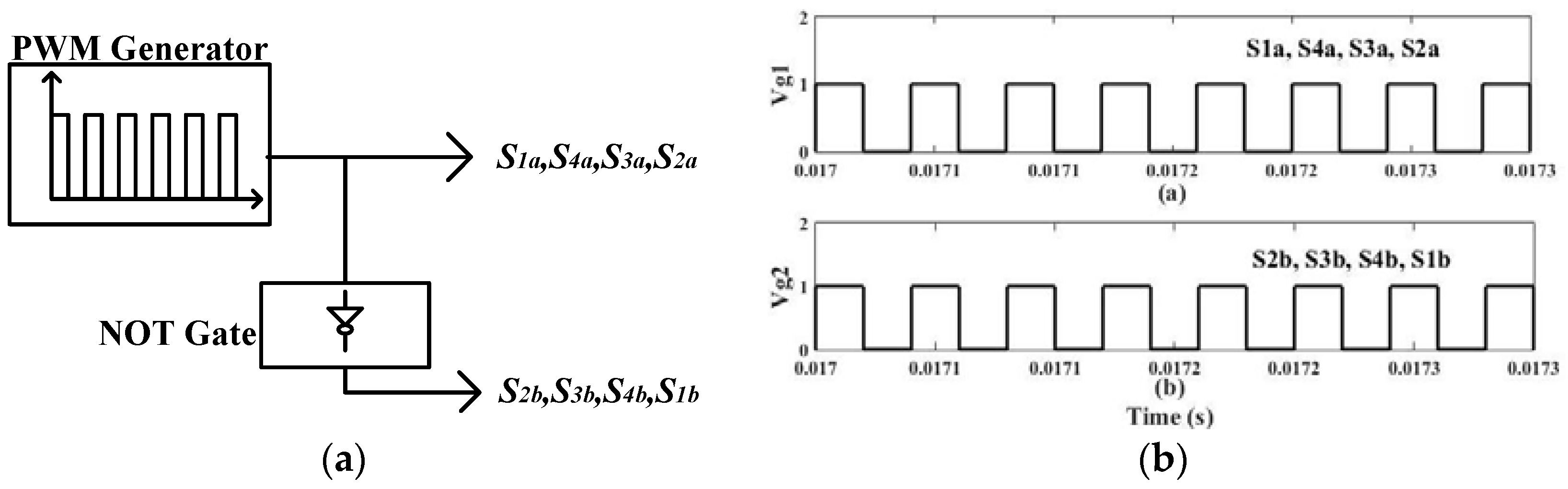
2.2. Proposed Switching Technique for SPMC in IH Applications

In the proposed switching technique, only two PWM signal (i.e., Vg1 and Vg2) is required to operate SPMC as a resonant converter for IH applications. Regarding the generation of these pulses, a controller has been designed which is based on embedded system. The IH system based on SPMC topology using proposed controller which generates pulses Vg1 and Vg2 is shown in Figure 3. In this figure, the proposed controller comprises of zero crossing detector (ZCD), microcontroller unit and isolation circuit. For generation of pulses, the AC voltage (230 Vr.m.s) is stepped down to 12 Vr.m.s. Subsequently, this stepped down AC is given to ZCD block that is used to synchronize the pulses (Vg1 and Vg2) with the input AC supply. Now this output of ZCD is fed to the microcontroller Atmega 2560, which detects the rising and falling edge of the pulse, i.e., Vg (generated from the ZCD). According to the program fed to the microcontroller, when it detects the rising edge of the pulse (Vg), it generates the pulse (Vg1) of 10 ms (if the 100 Hz output of the converter is required). When it detects the falling edge, again it generates a pulse (Vg2) of 10 ms, but this pulse is in complete phase opposition from previous pulses, shown in Figure 4b. For generating a higher frequency of the pulse, the time period of the pulses should be considered less during programming. The detailed explanation of prototype implementation and the experimental results of this proposed controller regarding generation of pulses (Vg1 and Vg2) have been well explained in Section 4.
Now, with the help of these two pulses (Vg1 and Vg2), frequency synthesization has been well presented. The proposed configuration (power circuit of SPMC as in Figure 3) of SPMC as a frequency changer/resonant converter for IH applications is shown in Figure 4a–c which shows the waveform of SPMC as a frequency changer (i.e., at 100 Hz output) and as a resonant converter (i.e., at high frequency of output) using proposed control technique. In Figure 4a, Vi is the input supply voltage, Ls and Cf are the input inductor and filter capacitor respectively, that are used to reduce the electromagnetic interference (EMI) effect and also prevent the HF component of voltage/current (generated from the load side). Four bidirectional switches are used and each of them is a combination of two IGBTs and two diodes. It is already known that the resonant inverter works at a resonant frequency (Equation (1)). However, for the IH application, the switching frequency of the resonant inverter should be kept higher or lower than the resonant frequency to ensure zero voltage switching (ZVS) or zero current switching (ZCS) conditions for reducing the switching losses across switches [36]. In this work, ZVS condition has been achieved by maintaining the switching frequency higher than the resonant frequency. To analyze the system behaviour, IH coil and its load can be modelled as the series equivalent of R0 and L0, which is already shown in Figure 4a. In addition, the resonating capacitor (Cr) is connected in series with R0 and L0 to create the series resonance condition.
The operation of the SPMC using modified switching technique for IH application can be understood by using 4 modes of operation according to the polarity of the input voltage. Modes 1 and 2 are explained for the positive half cycle and Modes 3 and 4 are explained for the negative half cycle.
Mode 1 (0 < t < t1): In the positive half cycle, switches S1a, S4a, S2b, S3b are forward biased and S3a, S2a, S4b, S1b are reverse biased. Forward biased switches can be turned ON at any time between 0 to t1 by applying the pulses (Vg1 and Vg2). During this time 0 < t < t1, among the forward biased switches only two switches (i.e., S1a and S4a) are receiving PWM signal (Vg1) shown in Figure 4b. Owing to this, only S1a and S4a will be turned ON to create a path for the load current that is, S 1 a D 1 l o a d S 4 a D 7 shown in Figure 5a.
Mode 2 (t1 < t < t2): This mode is also for the positive half cycle. In this mode, since switches S1a and S4a are not receiving PWM signal (Vg1), these switches get turned OFF. Now in this mode, among the forward biased switches, only two switches (S2b and S3b) are receiving PWM signal (Vg2) shown in Figure 4b. Owing to this, S2b and S3b will be turned ON. Now, the path for the load current becomes reverse i.e., S 2 b D 3 l o a d S 3 b D 5 shown in Figure 5b.
Mode 3 (t2 < t < t3): In the negative half cycle, switches S1a, S4a, S2b, S3b are reverse biased and S3a, S2a, S4b, S1b are forward biased. Forward biased switches can be turned ON at any time between t2 to t3 by applying the pulses (Vg1 and Vg2). During this time t2 < t < t3, among the forward biased switches only two switches (i.e., S3a and S2a) are receiving PWM signal (Vg1) shown in Figure 4b. Owing to this, only S3a and S2a will be turned ON to create a path for the load current that is, S 3 a D 6 l o a d S 2 a D 4 shown in Figure 6a.
Mode 4 (t3 < t < t4): This mode is also for the negative half cycle. In this mode, since switches S3a and S2a are not receiving PWM signal (Vg1), these switches gets turned OFF. Now in this mode, among the forward biased switches, only two switches (S4b and S1b) are receiving PWM signal (Vg2) shown in Figure 4b. Owing to this, S4b and S1b will be turned ON. Now, the path for the load current becomes reverse i.e., S 4 b D 8 l o a d S 1 b D 2 shown in Figure 6b.
The aforementioned four modes of operations have been applied and are illustrated in Figure 5 and Figure 6.
From the above modes of operation it can be concluded that SPMC can work as a frequency changer device as well as resonant converter. From the circuit diagram shown in Figure 4a, it can be seen that there are two paths for load current in each half cycle. In the positive half cycle, the two paths for the load current are S1a, D1, load, S4a, D7 and S2b, D3, load, S3b, D5, respectively. In the negative half cycle, the two paths for the load current are S4b, D8, load, S1b, D2 and S3a, D6, load, S2a, D4, respectively. Therefore, in this proposed switching algorithm, in each half cycle, the direction of load current could be changed depending on the time period of the conduction of switches. In other words, the desired output frequency of the load voltage/current depends on the switching frequency of the switches. Due to its frequency changer operation, it can be applied in IH application which has been shown in Figure 4c. By using the above modes of operation, switches’ operation status is given in Table 1.
There are several merits of the proposed switching strategy over conventional techniques [21]. Some of them are:
  • Compared to a previous switching strategy, the modified switching strategy has a simple but unique generation capability of resonant frequency or switching frequency which is the basic need of SPMC as a resonant converter for IH application.
  • Using this modified/proposed switching technique, SPMC can achieve a high frequency current very easily but using traditional/conventional switching technique, SPMC can generate only integral multiple of input supply frequency i.e., 50 Hz, 100 Hz, 150 Hz and so on. That is why previous switching topology cannot be applied in the field of IH applications.
  • Also, the design of the controller for the proposed technique is quite simple because it needs to generate only two pulses as compared to previously developed switching techniques in which four pulses are needed for synthesization of frequency. Owing to this, the proposed technique reduces the design complexity of the controller.
  • The proposed switching technique can be applied for both operation of SPMC i.e., as a frequency changer or as resonant converter.
Consequently, the proposed configuration of SPMC for IH applications shown in Figure 4a has been modelled as an RLC circuit, which consists of a resistor (Ro), an inductor (Lo) and a capacitor (Cr) can be used to analyze the system behavior. It should also be noted that, at the resonant frequency, maximum output power is transferred to the load. Owing to this, a practical converter for IH applications always works at equal to or greater than the resonant frequency. For analyzing the circuit of SPMC as a resonant converter for IH applications, the following equations have been applied:

2.2.1. Resonant Frequency

f r = 1 2 π L 0 C r
In terms of angular resonant frequency:
ω r = 1 L 0 C r

2.2.2. Characteristics Impedances

Z e q = L 0 C r = 1 2 π f r C r = 2 π f r L 0
In terms of angular frequency:
Z e q = L 0 C r = 1 ω r C r = ω r L 0

2.2.3. Load Quality Factor

Q = Z e q R 0 = 2 π f r L 0 R 0 = 1 2 π f r R 0 C r
In terms of angular frequency:
Q = Z e q R 0 = ω r L 0 R 0 = 1 ω r R 0 C r

2.2.4. Output Impedance of Equivalent Circuit (Figure 4a)

Z e q = R 0 + j ( 2 π f r 1 2 π f r C r ) = R 0 { 1 + j Q ( 2 π f n 1 2 π f n ) }
Z e q = R 0 1 + Q 2 ( 2 π f n 1 2 π f n ) 2
where 2 π f n = 2 π f 2 π f r , φ = arg { Z ( 2 π f ) } = arctan { Q ( 2 π f n 1 2 π f n ) } 0 .

2.2.5. Fundamental Output Voltage

V 0 = { V d , 0 < 2 π f s t < π V d , π < 2 π f s t < 2 π }
V m = 2 V d π

2.2.6. Ieq, That Is, Load Current Flowing Through Tank

i L o = I m sin ( ω t φ )
where I m = V m | Z e q | = 2 V d π | Z e q | = 2 V d cos φ π R o = 2 V d π R o 1 + Q 2 ( 2 π f n 1 2 π f n ) .

2.2.7. The Output Power

P o u t = I m 2 R 0 2 = 2 V d 2 π R o { 1 + Q 2 ( 2 π f n 1 2 π f n ) 2 }
In Equation (11), at ω n = 2 π f n = 1 , the circuit becomes resonant, therefore, maximum power is transferred to the load. Moreover, output power could be varied with the help of a different value of quality factor (Q).

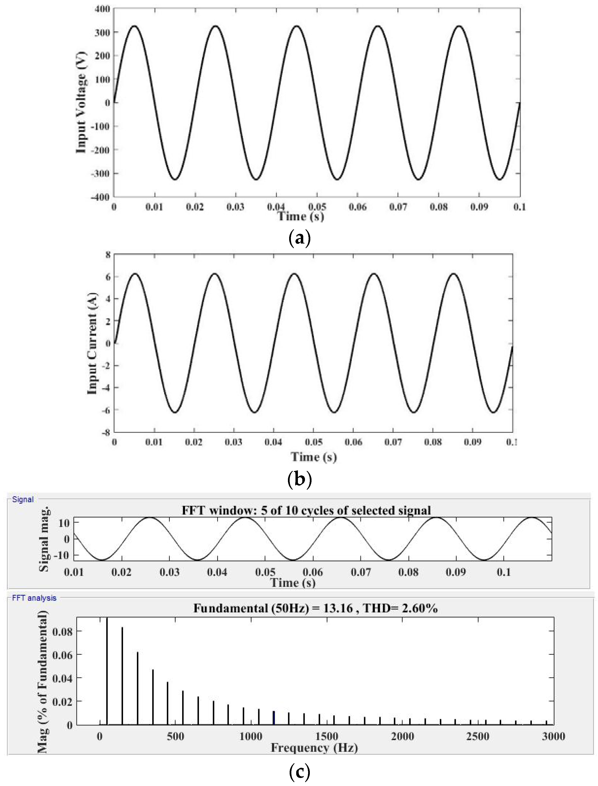
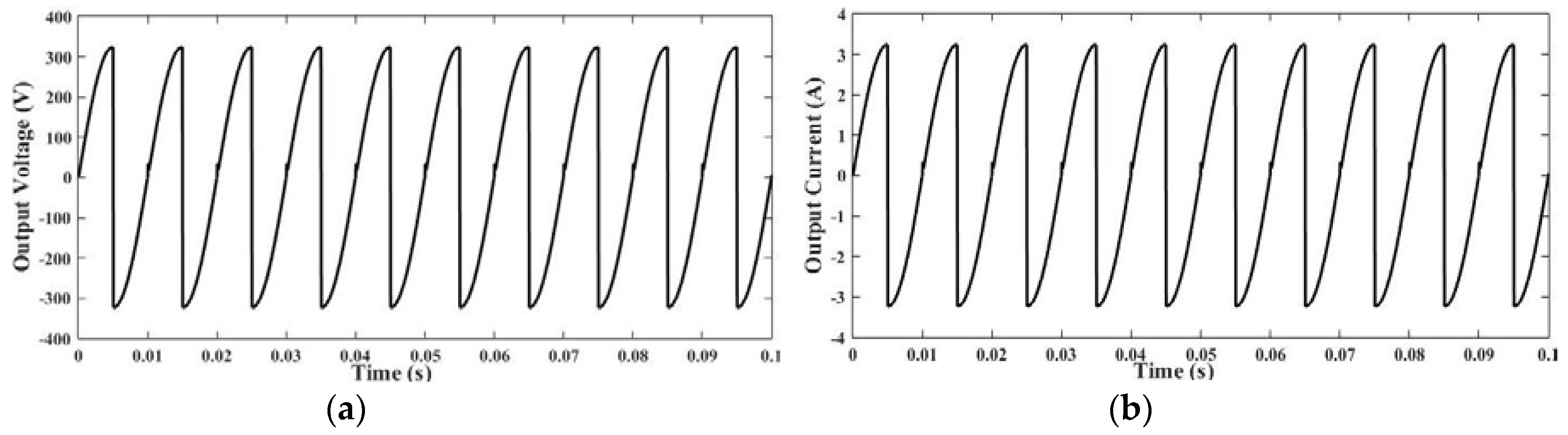
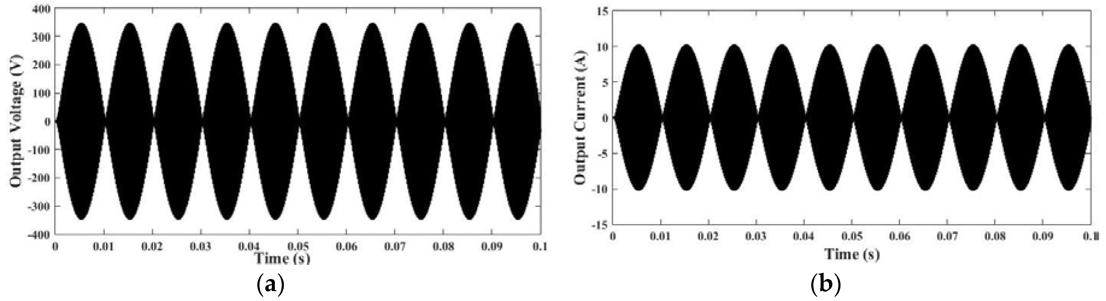
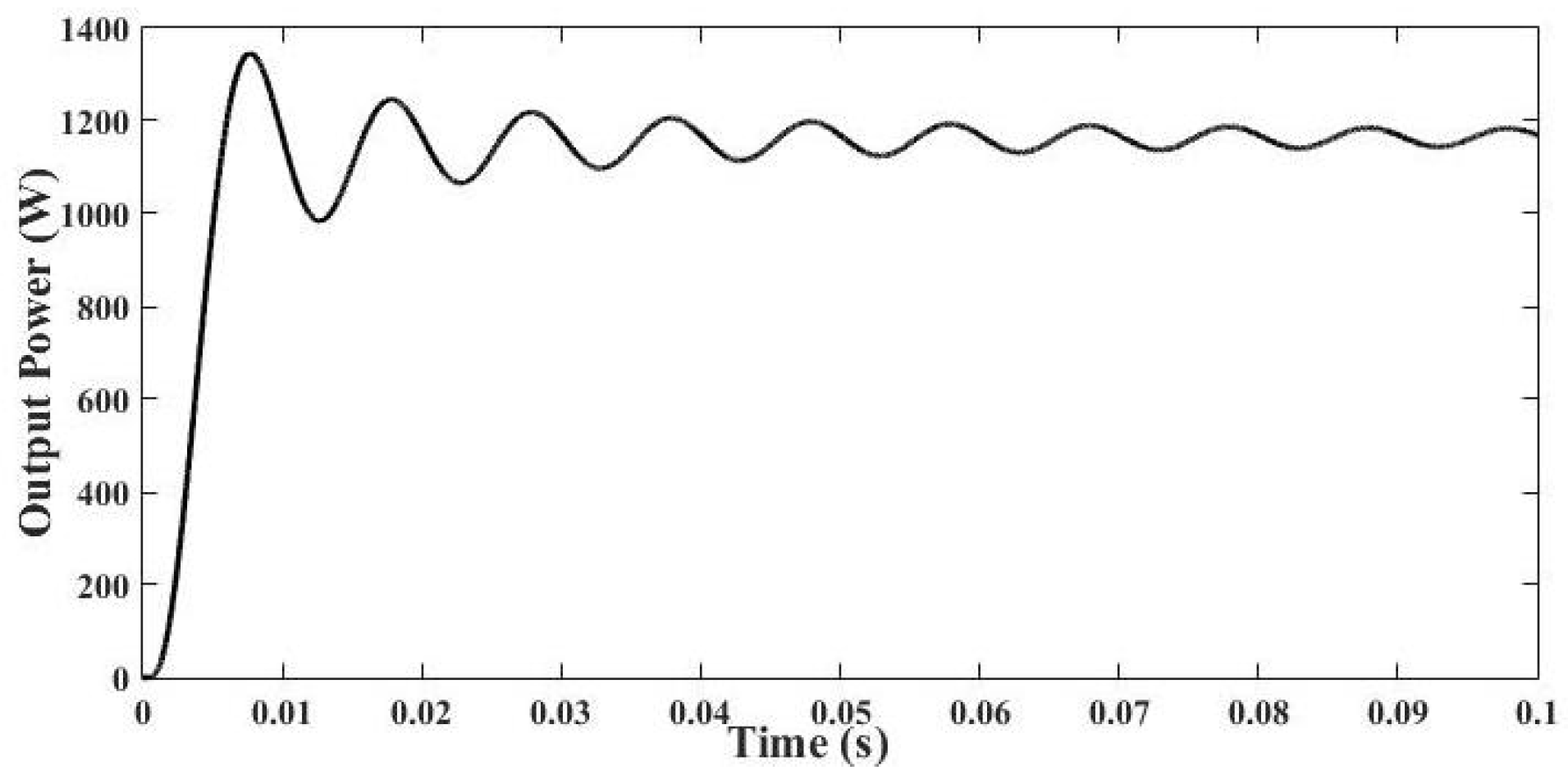
3. Simulation Results and Its Discussion

To validate the modified proposed technique, simulation has been done in MATLAB/SIMULINK (R2012a, Dhanbad, Jharkhand, India) environment by using parameters given in Table 2. Firstly, simulation has been done for the general SPMC under R (100 Ω) load to create different output frequencies, that is, 100 Hz, 150 Hz and 200 Hz, by using the modified proposed technique with experimental validation. Subsequently, simulation has been done for the SPMC as a resonant converter, which works at a switching frequency of 25 kHz (Table 2) in order to validate the modified technique. Various results and waveforms of voltage and current have been taken along with THD of the input current through the simulation. Figure 7a shows the PWM controller that generates pulses (Vg1 and Vg2) of different frequencies. Figure 7b depicts the simulation results of pulses waveform (Vg1 and Vg2), generated by the PWM controller are given to the switches of SPMC converter to generate output voltage/current of a different step up frequency. The frequency and duty cycle of this pulse is maintained at 25 kHz and 50% respectively. By changing the time period of this PWM controller, the desired output frequency can be achieved. Basically, in this study, SPMC as a resonant converter for IH application is focused upon. This direct AC–AC converter has been designed to operate at a resonant frequency (switching frequency) of 25 kHz, which is greater than the frequency as per calculation from equation (1), with the parameters of L0 = 52.7 × 10⁻⁶ and Cr = 0.8 × 10⁻⁶ to satisfy the criteria of ZVS.
Figure 8a,b shows the waveforms of the input voltage (230 Vr.m.s) and input current. Figure 8c shows the value of THD in input current which was found to be 2.60%. To achieve this low THD value, a passive filter has been used which is an essential part of SPMC when it needs to operate as resonant converter for IH system. The HF switching results in the generation of HF harmonics that has an inherent tendency to back flow towards the supply side and deteriorate the power quality, resulting in a wide variety of problem like distortion in the grid voltage/current. Thus, the low value of THD of 2.60% in input current ensures the attenuation of HF harmonics and makes the power supply of IH system practically viable. As aforementioned, first simulation has been done for generating 100 Hz output using proposed switching technique which is shown in Figure 9a,b. Figure 10 shows the typical simulated results of output voltage and load current for SPMC as a resonant converter in IH applications. The root mean square (RMS) value of output voltage and load current are 225.2 V and 5.162 A, which have been calculated from the continuous RMS block. Therefore, average output power can be calculated by using the product of these two RMS values. Here, for the calculation of maximum output average power, ideally cos ϕ (power factor) is taken as unity because it is known that at resonant frequency, capacitive reactance and inductive reactance becomes equal, but it is not the case for practical purposes.
P = V I cos ϕ ; cos ϕ 1
P = 225.2 × 5.162 × 1 = 1162   W
Figure 11 depicts the simulated result of the output average power. In this study, the passive filter has been designed to protect from the high-frequency component at the input side. The equivalent circuit of the passive filter is shown in Figure 12a. From this figure, it can be observed that Zeq is too high at a higher resonant frequency (switching frequency), which prevents the flow of HF component current at the grid side. The simulated voltage waveform across the filter capacitor is shown in Figure 12b. This figure shows how the HF component has been blocked at the input side.
In this section, various simulation results of the proposed SPMC as a resonant converter for IH application using the modified switching technique and its performance analysis have been provided. As aforementioned, the RLC circuit, which is modeled as an IH load, has been used for analysis. In the next section, prototype implementation of SPMC as a resonant inverter and its results has been discussed.

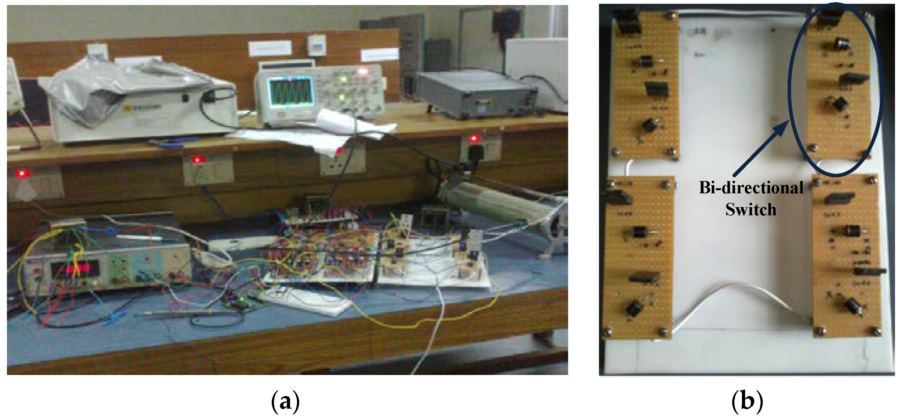
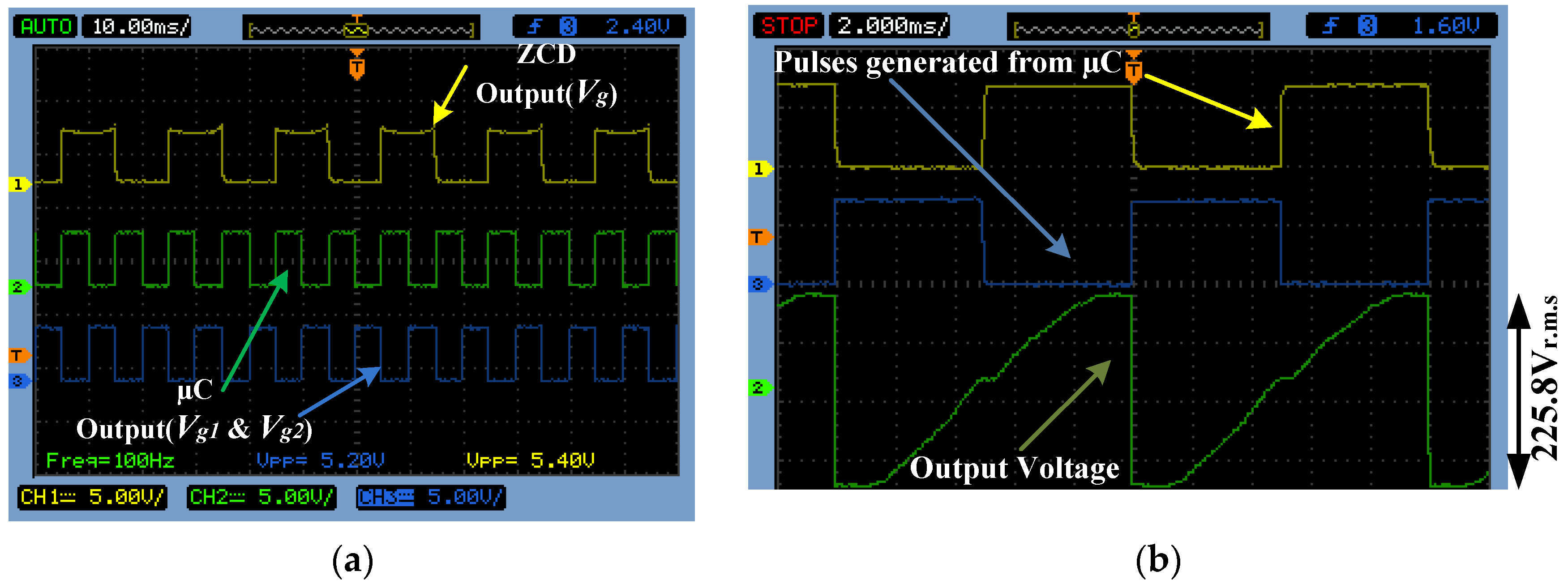
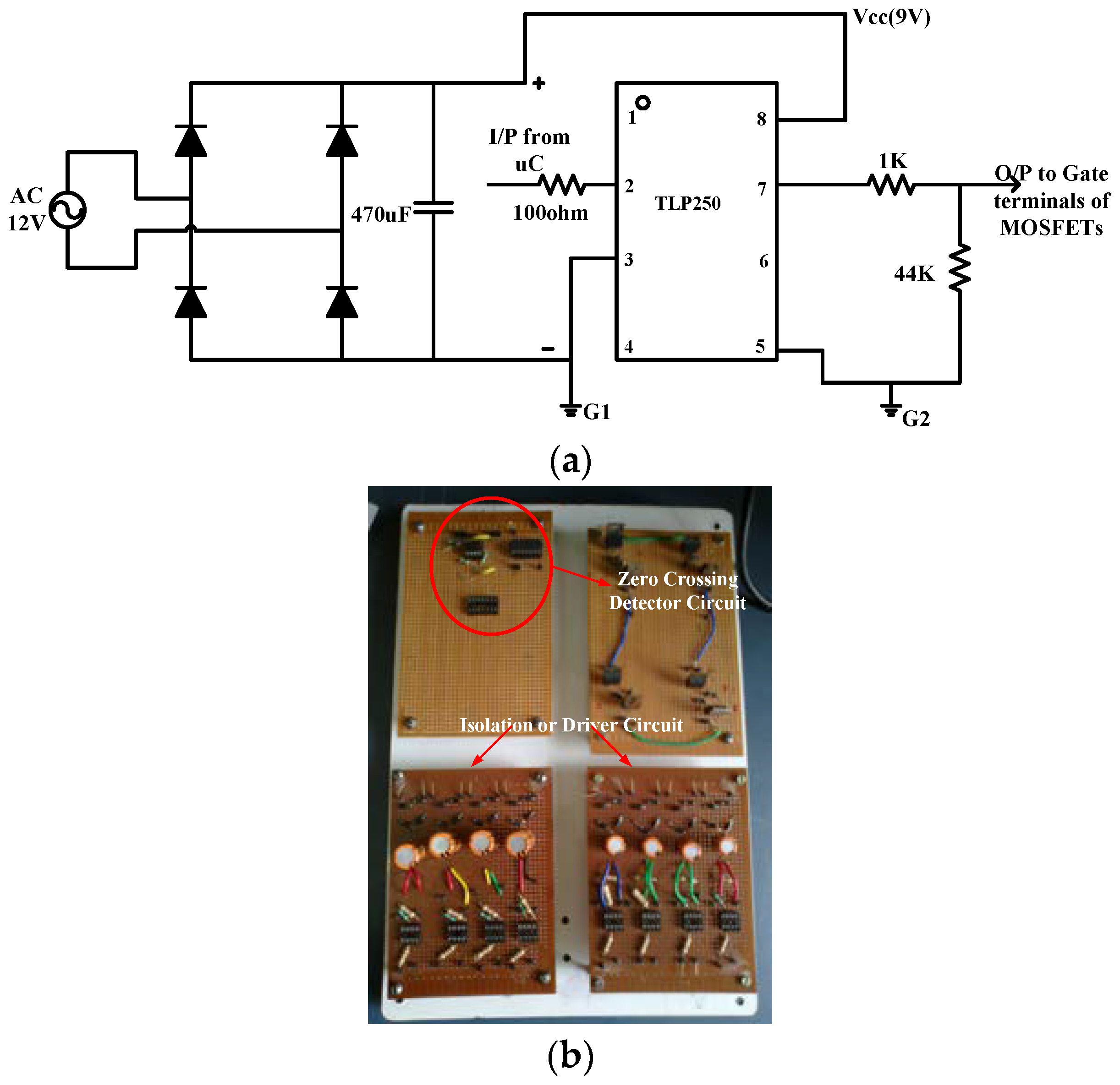
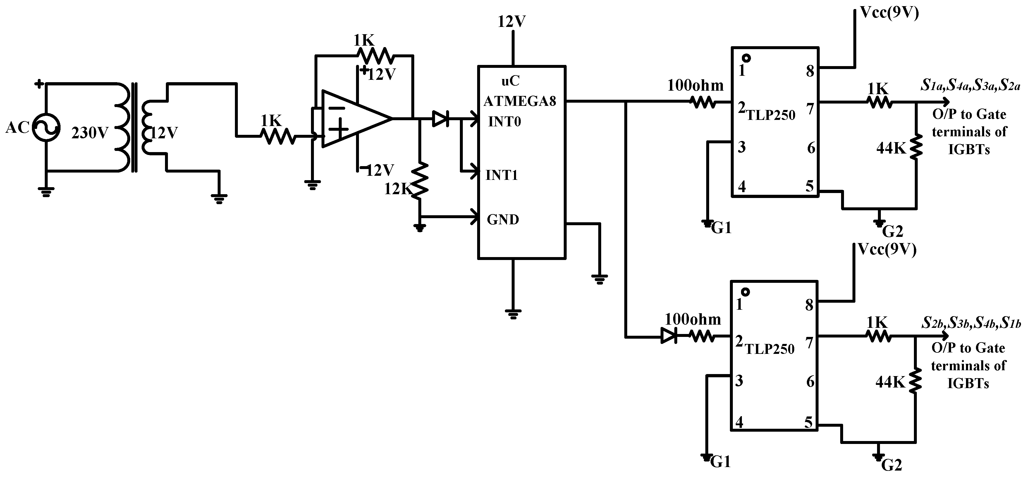
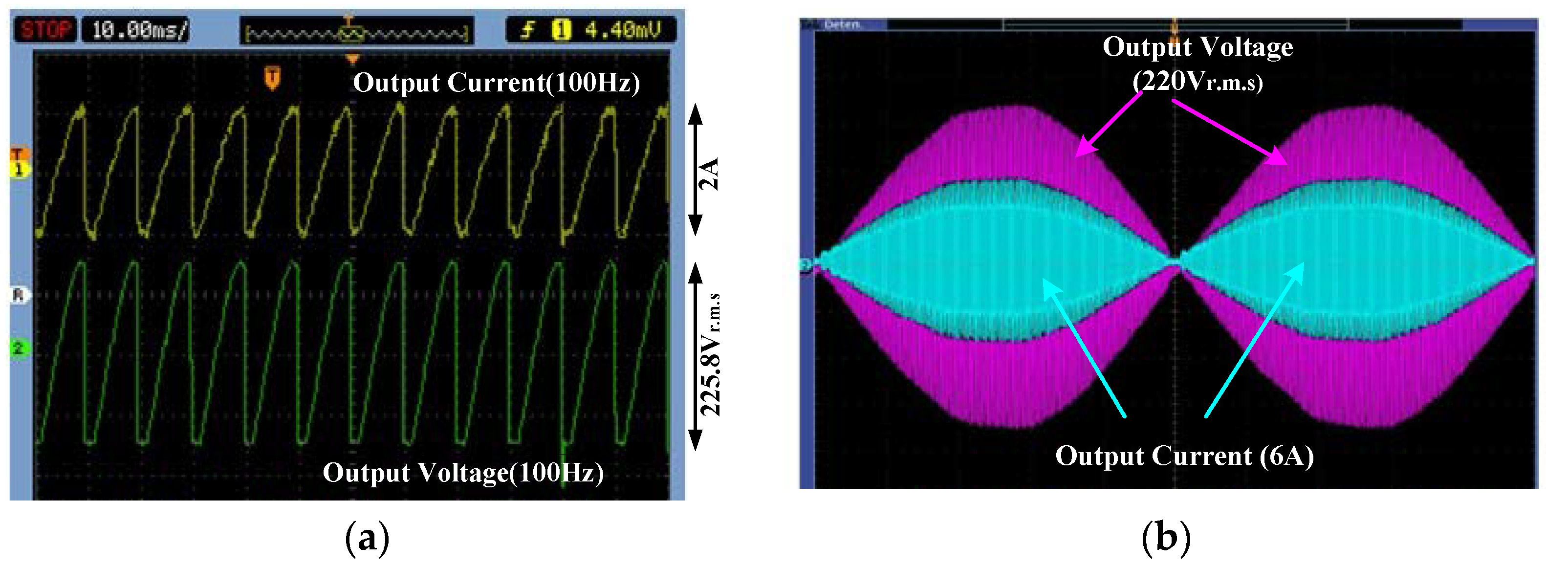
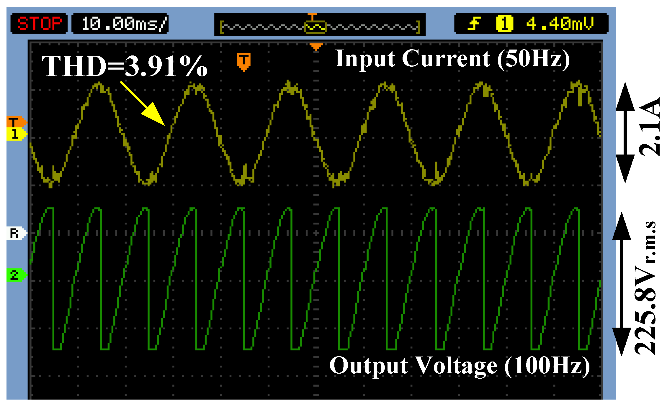
4. Prototype Implementation and Its Results

To verify the converter performance followed by simulation result of SPMC, based on proposed switching technique for IH application, a prototype laboratory set up has been developed with resistive load which is shown in Figure 13. When this converter needs to be operated as a resonant converter for IH application, IH coil could be connected instead of resistive load. An embedded technology-based Arduino mega 2560 (Mouser electronics, Banglore, India) is used for generating PWM for the gate of the switches. In this study, firstly, a prototype of the SPMC has been tested for 100 Hz output (i.e., as a frequency changer operation) using the modified technique. For this, only the resistive load is assumed. Subsequently, this converter has been tested as a resonant inverter for IH application using the same modified technique to show the uniqueness of developed technique.
The implementation of the hardware circuit is divided into four parts: (a) designing of Power circuit; (b) ZCD circuit; (c) controller; (d) isolation and protection circuit. For designing of the power circuit, eight IGBTs and eight diodes have been used. Two IGBTs and two diodes have been used for making one bidirectional switch. In this study, four bidirectional switches have been used for a prototype implementation of the power circuit of SPMC, which has been shown in the Figure 13b. It is known that ZCD is used to detect every zero crossing of input AC voltage for synchronization of pulses. ZCD has been implemented with the help of Opamp IC741 (Fairchild semiconductor, San Jose, CA, United States), which works as a voltage amplifier. A synchronized pulse (Vg) generated from the ZCD is given to interrupt pin of Atmega 2560 (Mouser electronics, Banglore, India) (i.e., digital pin 2 and digital pin 3) which is assigned as INT0 and INT1, detects the rising and falling edge of the pulse i.e., Vg (generated from the ZCD). As explained in Section 2.2, that according to program fed to the microcontroller, when it detects the rising edge of the pulse (Vg), it generates the pulse (Vg1) of 10 ms (if the 100 Hz output of the converter is needed). Similarly, when it detects the falling edge, again microcontroller generates a pulse (Vg2) of 10 ms, but this pulse is in complete phase opposition from previous pulse. The experimental validation of synchronized pulse is shown in Figure 14a,b shows the validity of synchronization of output voltage with respect to pulses (Vg1 and Vg2).
After the synchronized pulses (Vg1 and Vg2) generation, it is given to the isolation circuit which isolates the converter (higher power level) and controller part (lower power level). The supply for the microcontroller and isolation circuit is given through a diode rectifier, which is shown in the block diagram of Figure 3. Subsequently, an isolation circuit has been prepared which is also called the gate driver circuit. For this, TLP250 optocoupler has been used. The circuit diagram and prototype implementation of the isolation or driver circuit are shown in Figure 15a,b, respectively. The output pulses (Vg1 and Vg2) from the isolation circuit are given to the switches of SPMC power circuit.
As discussed in Section 2.2, proposed controller comprises of three main units i.e., ZCD unit, microcontroller unit and isolation circuit unit. On combining these three units, the detailed hardware circuit diagram of the controller is shown in the Figure 16.
As aforementioned, using the modified technique, SPMC is operated first as a frequency changer (which converts 50 Hz grid frequency to 100 Hz with the input of 230 Vr.m.s) with a resistive load and later, it is tested as a resonant converter for IH application. Figure 17a,b shows the experimental results of SPMC as a frequency changer (at 100 Hz output voltage/current) and SPMC as a resonant converter for IH applications at a frequency of 25 kHz which validate simulation results. As seen from the Figure 17a,b, current and voltage are almost in the same phase. So experimentally, the load power factor in case of when SPMC has operated as a frequency changer (i.e., at 100 Hz output on resistive load) was found to be 0.98 which is quite close to unity. In the case of when SPMC has operated as resonant converter for IH applications was found to be 0.91. Figure 18 shows the experimental result of output voltage with respect to input current which validate that output is perfectly synchronized with input supply. The value of THD for the input current is experimentally found to be 3.91% which is quite low. Various experimental results of voltage and current waveform under R load or IH coil have been taken in a 200 MHz digital signal oscilloscope (DSO) using a current sensor probe to verify the validity of proposed/modified switching algorithm. It has been found that, the proposed technique can be used in the field of IH applications.

5. Conclusions

In this proposed work, a cogent switching algorithm has been employed for direct conversion of utility frequency to HFAC through SPMC topology for IH applications. The algorithm requires less number of components along with fewer PWM signals as compared to the conventional IH system, thus leading to reduction in the cost and complexity of the controller. This direct AC to high frequency AC conversion based on proposed switching algorithm enhances the overall efficiency of the IH system. Various simulation and experimental results corroborate the potential pragmatic applications of the SPMC as a resonant converter using the proposed switching technique to generate 25 kHz current/voltage directly from the 50 Hz grid frequency. It has the additional ability of reducing switching losses by incorporating a ZVS condition, high power factor and low input THD which improve the power quality at the input side.

Author Contributions

A.K. and P.K.S. developed the concept and also wrote this research article. A.K. designed and performed all the experiment. D.K.M. and M.J.B.R. thoroughly analyzed the data, simulation results and experimental results. All authors in this paper contributed equally.

Funding

This research received no external funding.

Acknowledgments

Authors acknowledges the “Indian Institute of Technology (Indian School of Mines), Dhanbad, India” for providing infrastructure support.

Conflicts of Interest

The authors declare no conflict of interest.

Appendix A

Table A1. List of components used for experimental design and their specification.
ComponentsSpecification/Ratings
GBT (IXRH40N120)
diode (10A7)
microcontroller
op-amp
diode (1N4007)
centre taped transformer
TLP250
IC Socket base
heat sink
resistance
capacitor
IH coil
(1200 V, 55 A)
(700 V, 10 A)
Atmega 2560
IC741
(1000 V, 1 A)
(12–0–12) V, 2 A
25 kHz
8 pin DIP
for IGBT
1 K, 12 K, 100 Ω, 44 K
470 μF
Litz wire based

References

  1. Acero, J.; Burdio, J.M.; Barragan, L.A.; Navarro, D.; Alonso, R.; Ramon, J.; Monterde, F.; Hernandez, P.; Llorente, S.; Garde, I. Domestic induction appliances. IEEE Ind. Appl. Mag. 2010, 16, 39–47. [Google Scholar] [CrossRef]
  2. Sarnago, H.; Lucia, O.; Mediano, A.; Burdio, J.M. Modulation scheme for improved operation of an RB-IGBT-based resonant inverter applied to domestic induction heating. IEEE Trans. Ind. Electron. 2013, 60, 2066–2073. [Google Scholar] [CrossRef]
  3. Sarnago, H.; Lucía, O.; Mediano, A.; Burdío, J.M. Class-D/DE dual-mode-operation resonant converter for improved-efficiency domestic induction heating system. IEEE Trans. Power Electron. 2013, 28, 1274–1285. [Google Scholar] [CrossRef]
  4. Lucia, O.; Burdio, J.M.; Millan, I.; Acero, J.; Puyal, D. Load-adaptive control algorithm of half-bridge series resonant inverter for domestic induction heating. IEEE Trans. Ind. Electron. 2009, 56, 3106–3116. [Google Scholar] [CrossRef]
  5. Lucía, O.; Maussion, P.; Dede, E.; Burdío, J.M. Induction heating technology and its applications: Past Developments, current Technology, and future challenges. IEEE Trans. Ind. Electron. 2011, 61, 2509–2520. [Google Scholar] [CrossRef] [Green Version]
  6. Mishima, T.; Takami, C.; Nakaoka, M. A new current phasor-controlled ZVS twin half-bridge high-frequency resonant inverter for induction heating. IEEE Trans. Ind. Electron. 2014, 61, 2531–2545. [Google Scholar] [CrossRef]
  7. Saha, B.; Kim, R.Y. High Power Density Series Resonant Inverter Using an Auxiliary Switched Capacitor Cell for Induction Heating Applications. IEEE Trans. Power Electron. 2014, 29, 1909–1918. [Google Scholar] [CrossRef]
  8. Lucía, O.; Burdío, J.M.; Millán, I.; Acero, J.; Barragán, L.A. Efficiency-oriented design of ZVS half-bridge series resonant inverter with variable frequency duty cycle control. IEEE Trans. Power Electron. 2010, 25, 1671–1674. [Google Scholar] [CrossRef]
  9. Sarnago, H.; Lucía, O.; Pérez-Tarragona, M.; Burdío, J.M. Dual-Output Boost Resonant Full-Bridge Topology and its Modulation Strategies for High-Performance Induction Heating Applications. IEEE Trans. Ind. Electron. 2016, 63, 3554–3561. [Google Scholar] [CrossRef]
  10. Singh, B.; Pandey, R. Improved Power Quality Buck-Boost Converter fed LLC Resonant Converter for Induction Heater. In Proceedings of the 2016 IEEE 6th International Conference on Power Systems (ICPS), New Delhi, India, 4–6 March 2016; pp. 1–6. [Google Scholar]
  11. Pham, H.; Fujita, H.; Ozaki, K.; Uchida, N. Dynamic analysis and control of a zone-control induction heating system. In Proceedings of the 2011 IEEE conference of Energy Conversion Congress and Exposition(ECCE), Phoenix, AZ, USA, 17–22 September 2011; pp. 4093–4100. [Google Scholar]
  12. Fujita, H.; Akagi, H. Pulse-Density-Modulated Power Control of a 4 kW, 450 kHz Voltage-Source Inverter for Induction Melting Applications. IEEE Trans. Ind. Appl. 1996, 32, 279–286. [Google Scholar] [CrossRef] [Green Version]
  13. Grajales, L.; Sabatk, J.A.; Wang, K.R.; Tabisz, W.A.; Lee, F.C. Design of a 10 kW, 500 kHz Phase-Shift Controlled Series-Resonant Inverter for Induction Heating. In Proceedings of the 1993 IEEE Industry Applications Conference Twenty-Eighth IAS Annual Meeting, Toronto, ON, Canada, 2–8 October 1993; pp. 843–849. [Google Scholar]
  14. Yilmaz, I.; Ermiş, M.; Çadirci, I. Medium-frequency induction melting furnace as a load on the power system. IEEE Trans. Ind. Appl. 2012, 48, 1203–1214. [Google Scholar] [CrossRef]
  15. Millan, I.; Burdio, J.M.; Acero, J.; Lucia, O.; Liorente, S. Series resonant inverter with selective harmonic operation applied to all-metal domestic induction heating. IET Power Electron. 2011, 4, 587–592. [Google Scholar] [CrossRef]
  16. Koertzen, H.W.; Van Wyk, J.D.; Ferreira, J.A. Design of the half-bridge series resonant converters for induction cooking. In Proceedings of the Power Electronics Specialist Conference (PESC), Atlanta, GA, USA, 18–22 June 1995; pp. 729–735. [Google Scholar]
  17. Dawson, F.P.; Jain, P. A Comparison of Load Commutated Inverter Systems for Induction Heating and Melting Applications. IEEE Trans. Power Electron. 1991, 6, 430–441. [Google Scholar] [CrossRef]
  18. Koertzen, H.W.; Ferreira, J.A.; Van Wyk, J.D. A comparative study of single switch induction heating converters using novel component effectivity concepts. In Proceedings of the 23rd Annual IEEE Power Electronics Specialists Conference (PESC), Toledo, Spain, 29 June–3 July 1992; pp. 298–305. [Google Scholar]
  19. Jimenez, O.; Lucia, O.; Urriza, I.; Barragan, L.A.; Mattavelli, P.; Boroyevich, D. An FPGA-based gain-scheduled controller for resonant converters applied to induction cooktops. IEEE Trans. Power Electron. 2014, 29, 2143–2152. [Google Scholar] [CrossRef]
  20. Nagarajan, B.; Sathi, R.R. Phase locked loop based pulse density modulation scheme for the power control of induction heating applications. J. Power Electron. 2015, 15, 65–77. [Google Scholar] [CrossRef]
  21. Idris, Z.; Hamzah, M.K.; Saidon, M.F. Implementation of single-phase matrix converter as a direct AC–AC converter with commutation strategies. In Proceedings of the 2006 37th IEEE Power Electronics Specialists Conference, Jeju, South Korea, 18–22 June 2006; pp. 1–7. [Google Scholar]
  22. Li, H.L.; Hu, A.P.; Covic, G.A. A direct AC–AC converter for inductive power-transfer systems. IEEE Trans. Power Electron. 2012, 27, 661–668. [Google Scholar] [CrossRef]
  23. Arevalo, S.L.; Zanchetta, P.; Wheeler, P.W.; Trentin, A.; Empringham, L. Control and implementation of a matrix-converter-based AC ground power-supply unit for aircraft servicing. IEEE Trans. Ind. Electron. 2010, 57, 2076–2084. [Google Scholar] [CrossRef]
  24. Kolar, J.W.; Schafmeister, F.; Round, S.D.; Ertl, H. Novel three-Phase AC–AC sparse matrix converters. IEEE Trans. Power Electron. 2007, 22, 1649–1661. [Google Scholar] [CrossRef]
  25. Trentin, A.; Zanchetta, P.; Clare, J.; Wheeler, P. Automated optimal design of input filters for direct ac/ac matrix converters. IEEE Trans. Ind. Electron. 2012, 59, 2811–2823. [Google Scholar] [CrossRef]
  26. Yamamoto, E.; Hara, H.; Uchino, T.; Kawaji, M.; Kume, T.J.; Kang, J.K.; Krug, H.P. Development of MCs and its applications in industry. IEEE Ind. Electron. Mag. 2011, 5, 4–12. [Google Scholar] [CrossRef]
  27. Hosseini, S.H.; Sharifian, M.B.; Sabahi, M.; Yazdanpanah, A.; Gharehpetian, G.H. Bi-directional power electronic transformer for induction heating systems. In Proceedings of the 2008 Canadian Conference on Electrical and Computer Engineering, Niagara Falls, ON, Canada, 4–7 May 2008; pp. 347–350. [Google Scholar]
  28. Kim, Y.; Okuma, S.; Iwata, K. Characteristics and Starting Method of a Cycloconverter With a Tank Circuit for Induction Heating. IEEE Trans. Power Electron. 1988, 3, 236–244. [Google Scholar] [CrossRef]
  29. Sugimura, H.; Mun, S.P.; Kwon, S.K.; Mishima, T.; Nakaoka, M. Direct AC–AC resonant converter using one-chip reverse blocking IGBT-Based bidirectional switches for HF induction heaters. In Proceedings of the 2008 IEEE International Symposium on Industrial Electronics, Cambridge, UK, 30 June–2 July 2008; pp. 406–412. [Google Scholar]
  30. Salehifar, M.; Moreno-eguilaz, M.; Sala, V.; Romeral, L. A Novel AC–AC Converter Based SiC for Domestic Induction Cooking Applications. In Proceedings of the 2013 28th Twenty-Eighth Annual IEEE Applied Power Electronics Conference and Exposition (APEC), Long Beach, CA, USA, 17–21 March 2013; pp. 3216–3223. [Google Scholar]
  31. Nguyen-Quang, N.; Stone, D.A.; Bingham, C.M.; Foster, M.P. Single phase matrix converter for radio frequency induction heating. In Proceedings of the International Symposium on Power Electronics, Electrical Drives, Automation and Motion (SPEEDAM), Taormina, Italy, 23–26 May 2006; pp. 614–618. [Google Scholar]
  32. Mohite, S.B.; Gujarathi, P.K. A Design and Implementation of a Novel Multimode Single Phase Matrix Converter. In Proceedings of the 2010 IEEE Power Electronics Electrical Drives Automation and Motion SPEEDAM, Pisa, Italy, 14–16 June 2010; pp. 1227–1230. [Google Scholar]
  33. Nguyen-Quang, N.; Stone, D.A.; Bingham, C.M.; Foster, M.P. A three-phase to single-phase matrix converter for high-frequency induction heating. In Proceedings of the 2009 13th European Conference on Power Electronics and Applications, Barcelona, Spain, 8–10 September 2009; pp. 1–10. [Google Scholar]
  34. Nguyen-Quang, N.; Stone, D.A.; Bingham, C.M.; Foster, M.P. Comparison of single-phase matrix converter and H-bridge converter for radio frequency induction heating. In Proceedings of the 2007 European Conference on Power Electronics and Applications, Aalborg, Denmark, 2–5 September 2007; pp. 1–7. [Google Scholar]
  35. Jose, P.S.; Deepika, N.C.; Nisha, S.N. Applications of single phase matrix converter. In Proceedings of the 2011 International Conference on Emerging Trends in Electrical and Computer Technology, Nagercoil, India, 23–24 March 2011; pp. 386–391. [Google Scholar]
  36. Kumar, A.; Sadhu, M.; Das, N.; Sadhu, P.K.; Roy, D.; Ankur, G. A Survey on High-Frequency Inverter and Their Power Control Techniques for Induction Heating Applications. J. Power Technol. 2011, 97, 201–213. [Google Scholar]
Figure 1. (a) Conventional IH Topology and (b) Block diagram of proposed topology.
Electronics 07 00149 g001
Figure 2. (a) 1-ø matrix converter topology and (b) bi-directional switch (common emitter configuration mode).
Electronics 07 00149 g002
Figure 3. Proposed IH system using SPMC topology incorporated with proposed controller.
Electronics 07 00149 g003
Figure 4. Power circuit of SPMC and its output voltage waveform (a) SPMC as a resonant converter for (IH) application; (b) Output voltage waveform of SPMC as frequency changer operation (at 100 Hz output) and (c) Output voltage waveform of SPMC as resonant converter (at HF output) using modified switching technique.
Electronics 07 00149 g004
Figure 5. Positive mode of operation (a) Mode 1 and (b) Mode 2.
Electronics 07 00149 g005
Figure 6. Negative mode of operation (a) Mode 3 and (b) Mode 4.
Electronics 07 00149 g006
Figure 7. (a) PWM Controller; (b) Simulation results of pulses i.e., Vg1 and Vg2 (180° out of phase).
Electronics 07 00149 g007
Figure 8. Simulated waveforms of (a) input voltage (Vin) (b) input current (Iin) and (c) THD analysis of input current (Iin).
Electronics 07 00149 g008
Figure 9. Simulated waveforms of (a) Output voltage (Vout) and (b) Output current (Iout) at 100 Hz.
Electronics 07 00149 g009
Figure 10. (a) Simulated waveform of output voltage (Vout) and (b) simulated waveform of output current (Iout) as a resonant converter for IH application.
Electronics 07 00149 g010
Figure 11. Simulation results of output average power (P).
Electronics 07 00149 g011
Figure 12. (a) Passive filter and (b) voltage across capacitive filter.
Electronics 07 00149 g012
Figure 13. Experimental setup of (a) SPMC and its (b) bi-directional switch.
Electronics 07 00149 g013
Figure 14. (a) Experimental results of ZCD and microcontroller output. (Scale: 5 V/div) and (b) experimental validation of synchronized output w.r.t. pulses. (Scale: output voltage, 75 V/div and Time, 10 ms/div).
Electronics 07 00149 g014
Figure 15. (a) Circuit diagram and its (b) experimental setup of isolation or driver circuit.
Electronics 07 00149 g015
Figure 16. Circuit implementation of proposed controller for SPMC as a resonant converter for IH applications.
Electronics 07 00149 g016
Figure 17. (a) Experimental verification of simulated output voltage and current at 100 Hz i.e., as a frequency changer. (Scale: output voltage, 75 V/div; output current, 1 A/div and time, 10 ms/div) and (b) experimental validation of output voltage and current of SPMC as a resonant converter for IH applications at 25 KHz. (Scale: Output voltage, 35 V/div; output current, 2 A/div).
Electronics 07 00149 g017
Figure 18. Experimental results of output voltage w.r.t. input current (Scale: Output voltage, 75 V/div; input current, 1 A/div; and Time, 10 ms/div).
Electronics 07 00149 g018
Table 1. Switches operation status of SPMC.
Input Voltage (Vin)ModeSwitches StatusTime IntervalOutput Voltage (Vout)
Vin > 0Mode 1(S1a/S4a) ON
(S2b/S3b) OFF
0 to t1Vout > 0
Mode 2(S1a/S4a) OFF
(S2b/S3b) ON
t1 to t2Vout < 0
Vin < 0Mode 3(S3a/S2a) ON
(S4b/S1b) OFF
t2 to t3Vout > 0
Mode 4(S3a/S2a) OFF
(S4b/S1b) ON
t3 to t4Vout < 0
Table 2. Parameters used for the simulation.
SymbolParametersValue
VinInput Voltage230 Vr.m.s
LsFilter inductance20 mH
CfFilter Capacitance3 uF
fFundamental Frequency50 Hz
CrResonant Capacitor0.8 uF
L0Coil Inductance52.7 uH
R0Coil Equivalent Resistance5 Ω
P0Output Power for heating1100 W
fsResonance Frequency (Switching Frequency)25 kHz

