Article

High Frequency Transformer’s Parasitic Capacitance Minimization for Photovoltaic (PV) High-Frequency Link-Based Medium Voltage (MV) Inverter

1
School of Electrical Engineering, Pusan National University, Busandaehak-ro 63 beon-gil 2, Busan 46241, Korea
2
Institute of Robotics and Mechatronics, German Aerospace Center (DLR), 82234 Wessling, Germany
*
Author to whom correspondence should be addressed.
Electronics 2018, 7(8), 142; https://doi.org/10.3390/electronics7080142
Submission received: 18 June 2018 / Revised: 4 August 2018 / Accepted: 6 August 2018 / Published: 8 August 2018

Abstract

:
The high-frequency-based medium voltage (MV) inverter is used in renewable energy power sources for power transmission. However, power quality is compromised as a result of the increase in common mode noise currents by the high inter-winding parasitic capacitance in high-frequency link transformers. This fast voltage transient response leads to harmonic distortion and transformer overheating, which causes power supply failure or many other electrical hazards. This paper presents a comparative study between conventional and modified toroid transformer designs for isolated power supply. A half bridge high-frequency (10 kHz) MV DC–AC inverter was designed along with power source; a 680 W solar module renewable system was built. An FEM-simulation with Matlab-FFT analysis was used to determine the core flux distribution and to calculate the total harmonics distortion (THD). A GWInstek LCR meter and Fluke VT04A measured the inter-winding capacitance and temperature in all four transformer prototypes, respectively. The modified design of a toroid ferrite core transformer offers more resistance to temperature increase without the use of any cooling agent or external circuitry, while reducing the parasitic capacitance by 87%. Experiments were conducted along with a mathematical derivation of the inter-winding capacitance to confirm the validity of the approach.

Graphical Abstract

1. Introduction

A transformer plays a vital role in energy conversion and is at the heart of the electric power system. The transformer size decreases with increasing frequency, which allows for the building of smaller, less expensive, and compact portable electrical devices [1,2]. Therefore, high frequency power transformers are preferred over traditional frequency transformers (50–60 Hz) in the power electronic fields, such as switching power supplies; converters; and inverters, including medium voltage (MV) inverters, which offer a step-up transformer-less solution to interconnect photovoltaic (PV) arrays to the MV grid [3,4,5,6,7,8].
Green energy is a priority of many researchers because of population and industrial growth, which are leading the world towards an extensive rise of global warming threats and visible climate change. Therefore, renewable energy sources are in high demand, particularly solar and wind energy. These sources are projected to fulfill 50% of the energy requirement by the year 2050 [9]. On the other hand, the intermittent nature of these power sources is a major limitation to connecting them straight to electrical/electronic systems or national grids. This critical obstacle can be overcome using external devices, such as energy storage, converters, and inverters (see Figure 1) [10,11,12,13]. As a result of the high penetration of these high-frequency-based MV inverters into the renewable energy power plants, energy demands could be fulfilled for industries and home power requirements. However, these high-frequency links, for example, high-frequency transformer, H-bridge inverter dead time, and non-linear load, generates high harmonic content. This can cause serious damage to the equipment including overheating, power supply failure, or electric shock hazards [14,15]. Consequently, to protect the component and the connected loads from overheating and to provide a power supply without any disturbances, the power quality of these MV inverters needs to be taken into consideration [16,17,18,19].
An electromagnetic interference (EMI) in inverters can affect the power quality of transients, both short time and longtime deviation, which can cause harmonics. In these devices, harmonics can be categorized into two classes: common and differential conduction modes (CCM and DCM) [20,21,22]. The high-frequency transformer is one of the sources of EMI and contributes to the common mode harmonics because of the intrinsic coupling capacitance, and electric and magnetic fields [23]. The duty cycle is inversely proportional to the harmonics. Therefore, DCM operations of pulse-width modulation (PWM) converters increase the harmonics, which adds power losses in transformer windings. Similarly, high-frequency operation causes skin and proximity effects that elevate the harmonic losses, winding power losses, and rapid growth in the operating temperature [24,25]. On the other hand, high frequency winding losses and lowering the leakage inductance has been a major research focus, while the winding capacitance requires equally serious attention during the design of transformers. Capacitive coupling is one of the paths that can carry high frequency noise; premature resonance; electrostatic coupling to other circuits; and fast transient voltages from primary to secondary circuitry, which produces common mode noise currents and an increase in transformer temperature in the device, resulting in a deterioration of the overall system operation, noise, health, and safety threats.
This capacitive coupling is an eruption effect of a transformer parasitic, rooted by a wide range of capacitance across the transformer, which circulates as a result of winding arrangements. Therefore, the key to overcoming this critical hurdle is lowering the inter-winding capacitance. Conventional methods to reduce the emergence of capacitive coupling at the transformer include increasing the insulation between the primary and secondary winding or increasing the distance between the primary and secondary winding by winding them on opposite sides of the toroidal core. These changes in the transformer will, however, cause other drawbacks, such as high leakage inductance, larger physical size, and poor inductive coupling. Accordingly, conventional methods are not completely effective in improving the power quality. On the other hand, previous studies [26,27,28,29,30,31,32] examined the techniques on smart transformers fuzzy logic based transformers by winding using fiber optic sensors and certain oils for cooling the transformer. They, however, were arranged specifically for the coupling capacitance and temperature control and showed no significant difference when compared with the less expensive conventional solutions.
The leakage inductance and primary/secondary capacitance are mutually exclusive and are governed by the distance between the windings and the unwounded core. As a result of this, it is difficult to achieve both low capacitive coupling and a high degree of inductive coupling in a power transformer [33,34]. To circumvent this inherent tradeoff in this study, the conventional toroid ferrite core transformer was modified by an additional 3D printed polylactic acid (PLA) mold, which separates the primary and secondary windings, and helps to implement unique sector winding. Although the distance between windings will introduce leakage inductance, there is some gain in capacitance due to the dielectric constant of PLA. However, the magnetic core geometry and winding arrangements have a large influence on self-capacitance and leakage inductance of the transformer and because of the addition of a mold, it enables access to various types of winding arrangements. This paper reports a comparative analysis on the high frequency-link MV inverter for power-quality improvement by effective subtraction of capacitive coupling and reducing the temperature increase without using any extra circuitry or cooling agents.

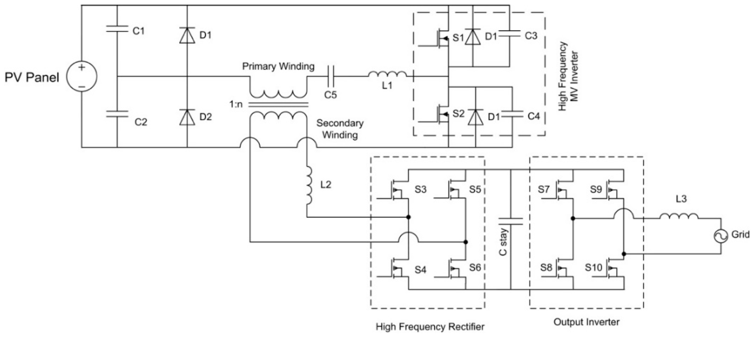
2. High-Frequency Link Based MV Inverter Design Consideration

2.1. Toroid Ferrite Core

To utilize the intrinsic ferrite material properties, it is essential to use a ring configuration of the ferrite core. Therefore, the toroid core was used in this paper, as it is commonly used for high-frequency square/sine wave-based applications, such as power input filters, ground-fault interrupters, common-mode filters, and pulse and broadband filters.
A 77 material ferrite toroid was used as the core for MV inverter high-frequency link transformer. Figure 2 presents a schematic diagram of the core and is defined by its outer diameter (A), inner diameter (B), and thickness (C) (See Table 1). Figure 3 shows how the increasing temperature affects the core properties and Table 2 presents toroid ferrite77 core material’s electrical properties.

2.2. Harmonic Current Contribution on Transformer Losses and Temperature Rise

Total harmonics distortion (THD) is a widely-used notion to define the harmonic content in alternating signals. This value is defined as the ratio sum of the powers of all harmonic components to the power of the fundamental frequency. THD is used for low, medium, and high voltage systems, where the current and voltage distortion is defined as THDI and THDV, and can be calculated using the following Equations (1)–(2).
T H D v = [ ( h 1 H   | V h | 2 ) 1 2 / | V 1 | ] × 100 %
T H D I = [ ( h 1 H   | I i h | 2 ) 1 2 / | I 1 | ] × 100 %
where h is the harmonic content order, and Vh and Ih are the voltage and current amplitude of order “h” harmonic component, respectively. V1 and I1 are the voltage and current amplitude of the fundamental component, respectively.
The International Electrotechnical Commission (IEC) 61727 imposes the limits for harmonics in the current—Electromagnetic compatibility (EMC)-Part 3–2: Limits for harmonics current emission. The IEEE Single Phase Harmonics Task Force (P1495) has set similar limitations. U.S. and European power systems are different from each other in many standards. Therefore, the United States should be different than the IEC stance. Thus, there is a flexibility to follow the certain standard (Table 3).
The losses in transformers can be classified as load loss (impedance loss), no-load loss (excitation loss), and total loss (no-load + load-loss). Load loss can be subdivided further into stray magnetic losses in the core, eddy currents, and resistive losses in the windings.
p t = p f h = 1 h = h max I h 2 h 2
where Pf is the eddy current loss at the fundamental frequency, and f and Ih are the fractions of the total RMS load current at the harmonic number h.

2.3. Circuit Operation

Figure 4 shows, A single-phase half bridge (10 kHz) is comprised of two power MOSFET (IRF 250) (Texas Instruments, Dallas, TX, USA), S1 and S2, which are driven by a DSP F28335 (Texas Instruments, Dallas, TX, USA) chip to generate a pulse width modulated waveform and feedback diodes, D1 and D2. These are called freewheeling diodes with two DC bus capacitors to stabilize the DC voltage. Two-stage power conversions with the help of the high-frequency transformer. High-frequency operation is possible at the first DC/DC stage and at the second stage modified amplitude of converted high-frequency AC voltage by high-frequency transformer secondary, which is connected to high-frequency rectifier AC/DC and an output inverter, which converts the DC voltage to the required frequency AC voltage in the case of utility grid 50/60 Hz.

3. Fabrication

This study examined a new design for the high-frequency link of an MV inverter, which mitigates the temperature increase occurring as a result of harmful harmonics by reducing the capacitive coupling at the high-frequency transformer. Four toroid core transformers with conventional and modified configurations, with 180° and 360° sector windings, were fabricated, and their THD, self-induced capacitance, and temperature were measured and compared. The transformer windings for all four configurations were wound manually. The core material, dimensions, copper wire, and a number of winding turns were the same for the conventional and modified configuration, as listed in Table 3. The difference between the conventional and modified configuration was a two-part mold that was mounted over the secondary windings and ferrite core. The primary winding was then wound over this additional piece of hardware, which altered the dimensions of the primary winding and provided scope to unique winding arrangements. The mold was printed using a 3D printer with a PLA filament material. This was comprised of two parts, top and bottom, each with a width of 0.5 mm each with very negligible extra weight and cost [35,36].

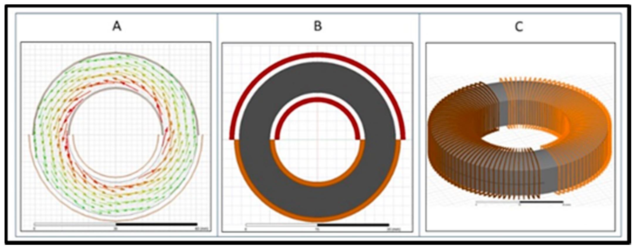
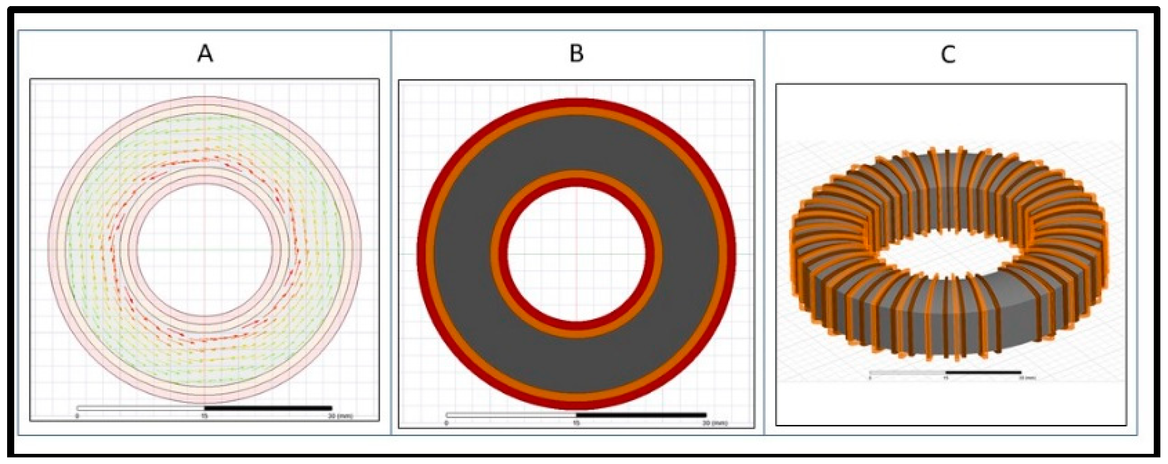
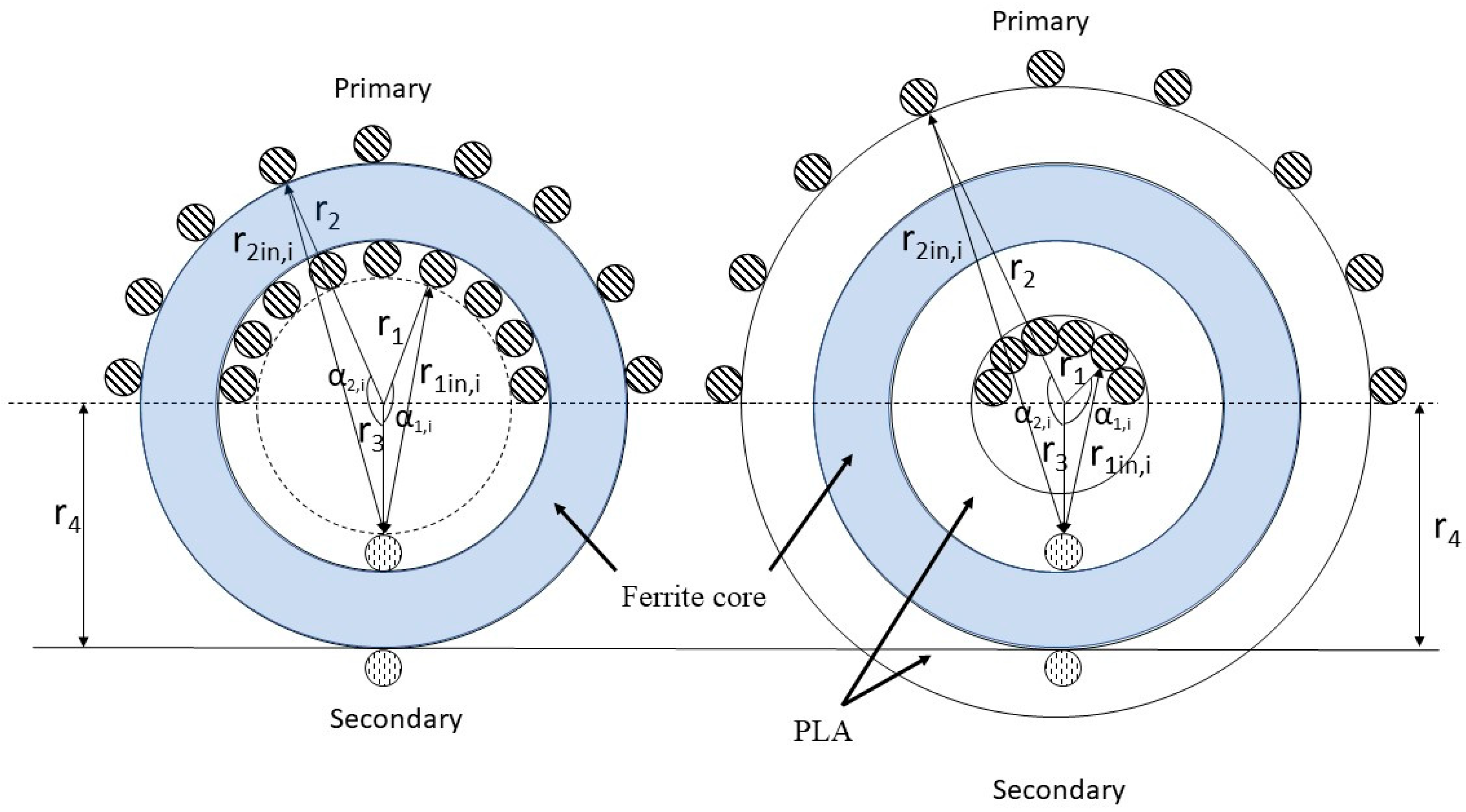
3.1. Case 1: Conventional Toroid Core Transformer with 180° Sector Windings

In this configuration, the entire secondary winding is distributed over the 180° sector of the toroid core in a back-and-forth manner. The other half of the toroid core is wound with primary windings in a similar manner, as shown in Figure 5.

3.2. Case 2: Modified Toroid Core Transformer with 180° Sector Windings

In this configuration, the secondary winding is distributed over the 180° sector of the toroid core in a back-and-forth manner, just as in the previous case. The two parts of the 3D printed mold using a PLA filament material were mounted over the ferrite toroid core and secondary windings, to completely encapsulate them. Owing to the assembly of the mold, the secondary winding is completely hidden, which leaves an entire 360° span for the primary winding. The initial experiments were carried out with the primary windings over the 360° sector and 180° sector of the core. On the other hand, the lowest leakage inductance was achieved when the primary had a 180° sector winding without overlapping the secondary winding, as shown in Figure 6.

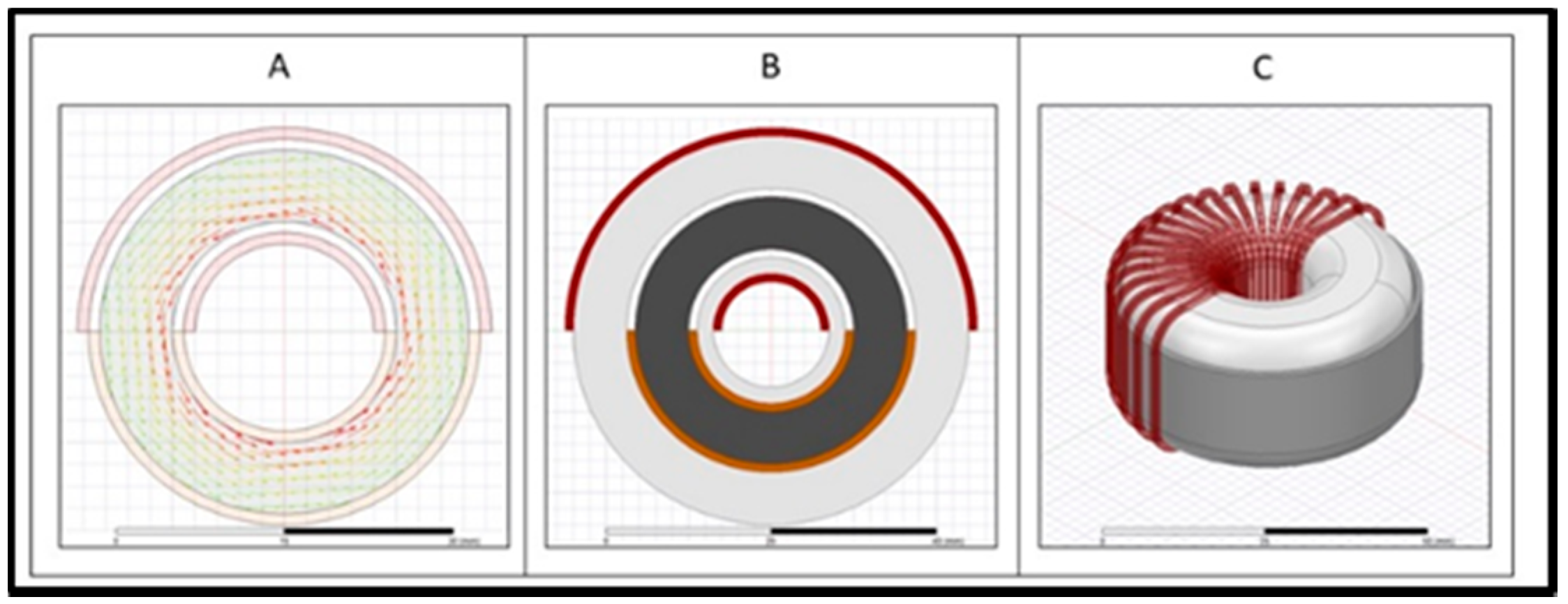
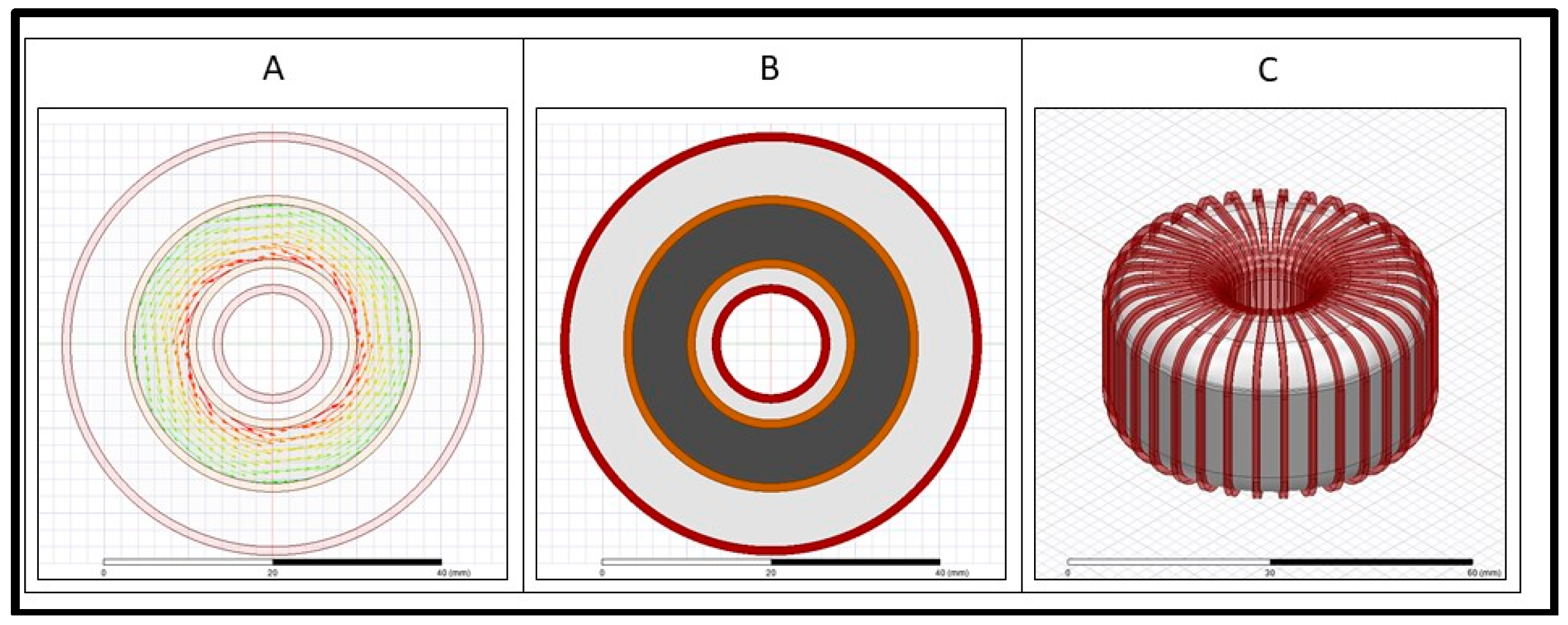
3.3. Case 3: A Conventional 360° Wound Toroid Core Transformer

In this case, the secondary winding is distributed over the entire 360° sector of the toroid ferrite core. The primary winding is also distributed over the 360° sector on top of the secondary winding (Figure 7).

3.4. Case 4: A Modified 360° Wound Toroid Core Transformer

In this case, the secondary winding is distributed over 360° sector of the toroid core in a back-and-forth manner, as in the former case. The toroid ferrite core along with the secondary winding is encapsulated with the 3D printed mold, over which the primary winding is wound around a 360° span (Figure 8).

4. Calculation of the Transformer Inter-Winding Capacitance

The general structure (2D, 3D, and flux flow in core) of the four designed transformer’s prototypes under test are illustrated in the fabrication section (3). In this section, prototype transformer calculations were carried out for inter-winding capacitance. Figure 9 shows the conceptual structure of case 1 and case 2 transformer prototypes for inter-winding capacitance calculation. Likewise, the capacitance for other prototypes can be evaluated in a similar manner.
Ferrite core material 77 has a negligible effect on parasitic capacitance; therefore, only winding configurations were taken into account. For the sake of simplicity, only one winding of the secondary side, which is wound on the ferrite core, is considered for calculation of inter-winding capacitance. The same position of the secondary winding is considered for all four cases.
The distance between the inner secondary winding and inner primary windings can be expressed as follows:
r 1 i n , i = r 1 2 + r 2 2 2 r 1 r 2 cos ( π 2 + π i n p )
where r1 is the distance from the center of the core to the inner primary windings, r2 is the distance from the center of the core to the outer primary windings, r3 is the distance from the center of the core to the inner secondary windings, r4 is the distance from the center of the core to the outer secondary windings (Figure 9), and np is the total number of primary turns. In all four cases, r 3 and r 4 values are the same, as secondary winding is wounded on the ferrite core and core dimension is same for all transformer prototypes. On the other hand, r 1 and r 2 values will vary with respect to each case, for example, r 1 , for case 4 ( r 1 ,   4 ) and case 2 ( r 1 ,   2 ) will be same, but they are less than case 3 ( r 1 ,   3 ), which in turn is less than case 1 ( r 1 ,   1 ). The details of r 1 , r 2 , r 3 , r 4 for the four different configurations are given as follows:
A :   r 1 ,   4 = r 1 ,   2 < r 1 ,   3 < r 1 ,   1 B :   r 2 ,   1 < r 2 ,   3 < r 2 ,   2 = r 2 ,   4 C :   r 3 ,   1 = r 3 ,   2 = r 3 ,   3 = r 3 ,   4 D :   r 4 ,   1 = r 4 ,   2 = r 4 ,   3 = r 4 ,   4
The static capacitance between the inner primary and inner secondary is as follows:
C 1 i n , i = d π l 1 2 r 1 i n , i = d π l 1 2 r 1 2 + r 2 2 2   r 1 r 2 cos ( π 2 + π i n p )
where Є∘ is the permittivity of free space, d is the diameter of the wire used for primary and secondary windings, and l1 is the overlapped length.
Assuming that the voltage potential distribution along the primary turn varies linearly,
V p [ i ] = i n p 1 V p
The total stored energy between the inner primary and secondary is as follows:
E 1 i n = 1 2 i = 0 n p 1 ( C 1 i n , i ( i n p 1 V p ) 2 )
Similarly, the capacitance between the inner primary–outer secondary, outer primary–outer secondary, and outer primary–outer secondary can be calculated. Equations (4)–(7) can be used to find the capacitance and energy for the other three cases as well (Table 4). The simulation was run on MATLAB to calculate the capacitance in all four cases. For the sake of simplicity and to ignore the repetitive process of inter-winding capacitance calculations, only one winding in the same position of the secondary side is considered for all four cases. To see the effect of inter-winding capacitance, we choose three primary winding for 180° conventional and modified configurations instead of 116, and 6 primary windings for 360° conventional and modified configurations instead of 220.
It can be seen from Table 5 that the inter-winding capacitance would be highest for case 3, followed by that for case 1, case 4, and case 2. These analytical calculations hold well with the experimental data for inter-winding capacitance, which is shown in the next section.

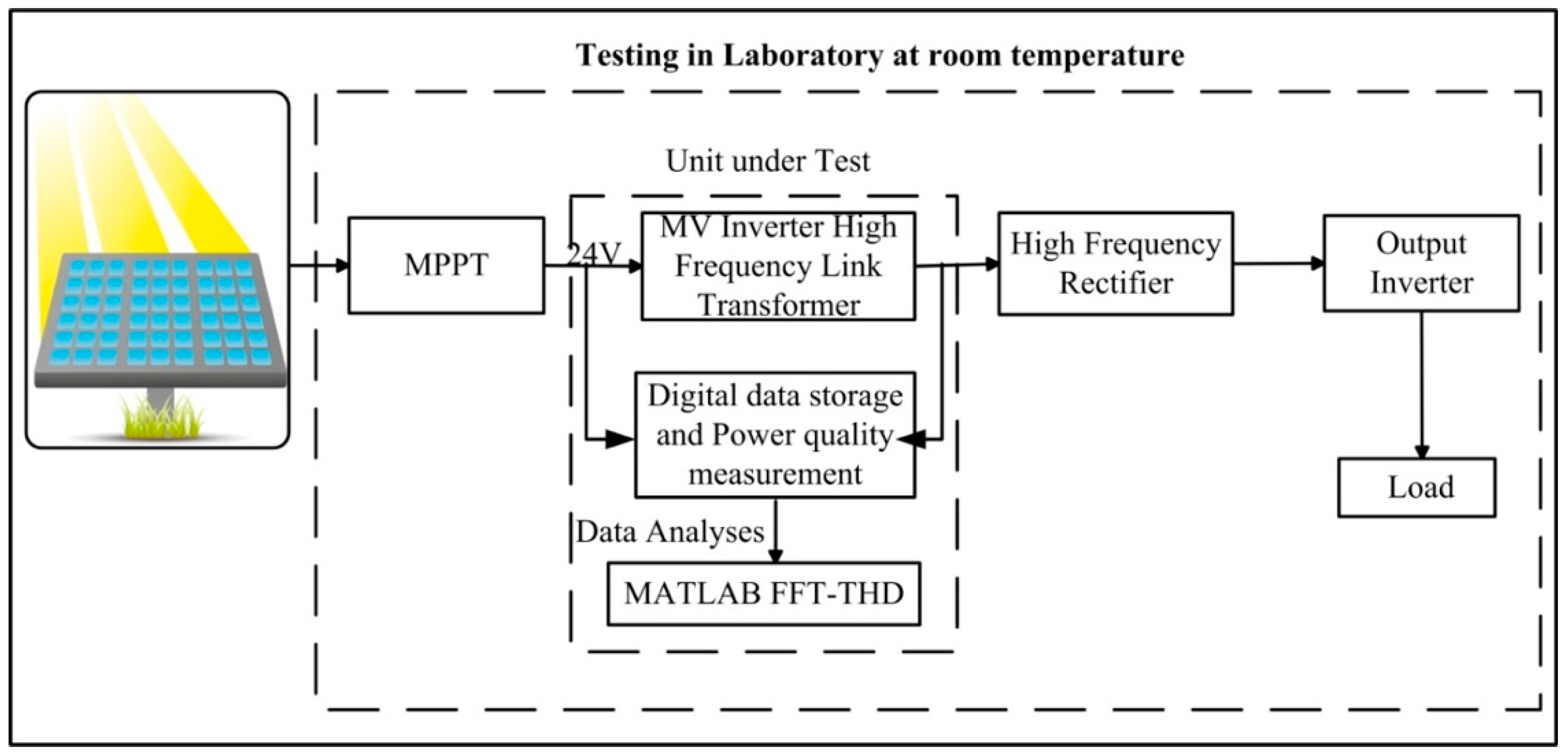
5. Experimental Setup

The high-frequency transformer temperature, capacitive coupling, and leakage inductance were measured using a Fluke VT04A (Fluke, Everett, WA, USA) Thermometer and GWInstek LCR (GWINSTEK, New Taipei City, Tucheng Dist., Taiwan) meter. The experiments were conducted at constant ambient room temperature, on the high-frequency link of a 1 kW half bridge MV inverter. Two 38 V, 350 W standalone solar modules connected in parallel served as input for the developed inverter. Owing to the addition of a 3D printed mold and sector winding, it was possible to have different winding arrangements. A number of modified toroid high-frequency transformers have been developed with different sector windings, such as 45°, 90°, 120°, 180°, 270°, and 360°. Figure 10 presents a block diagram of the experimental setup. The input and output waveforms of the transformer were stored, and the harmonic contents present in the waveform were analyzed by Matlab-FFT (MathWorks, Natick, MA, USA).

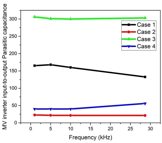
6. Results and Discussion

For the comparative analysis, we designed a conventional toroid transformer with the same 180° and 360° sector windings and the same core dimension. The comparative experimental studies stated that the proposed modified design succeeded in lowering the inter-winding capacitance (approximately 87%) and controlling temperature increase issues (less than 30°) when compared with conventional designs; detailed discussion based on sectored winding is shown below. Table 6 compares the THD of the aforementioned transformer prototypes. By comparative analysis of normative Table 3 and experimental result Table 6, it is clearly visible that all the prototypes have a minimum risk. Although, modified designs have registered more or less similar distortion compared with conventional designs.

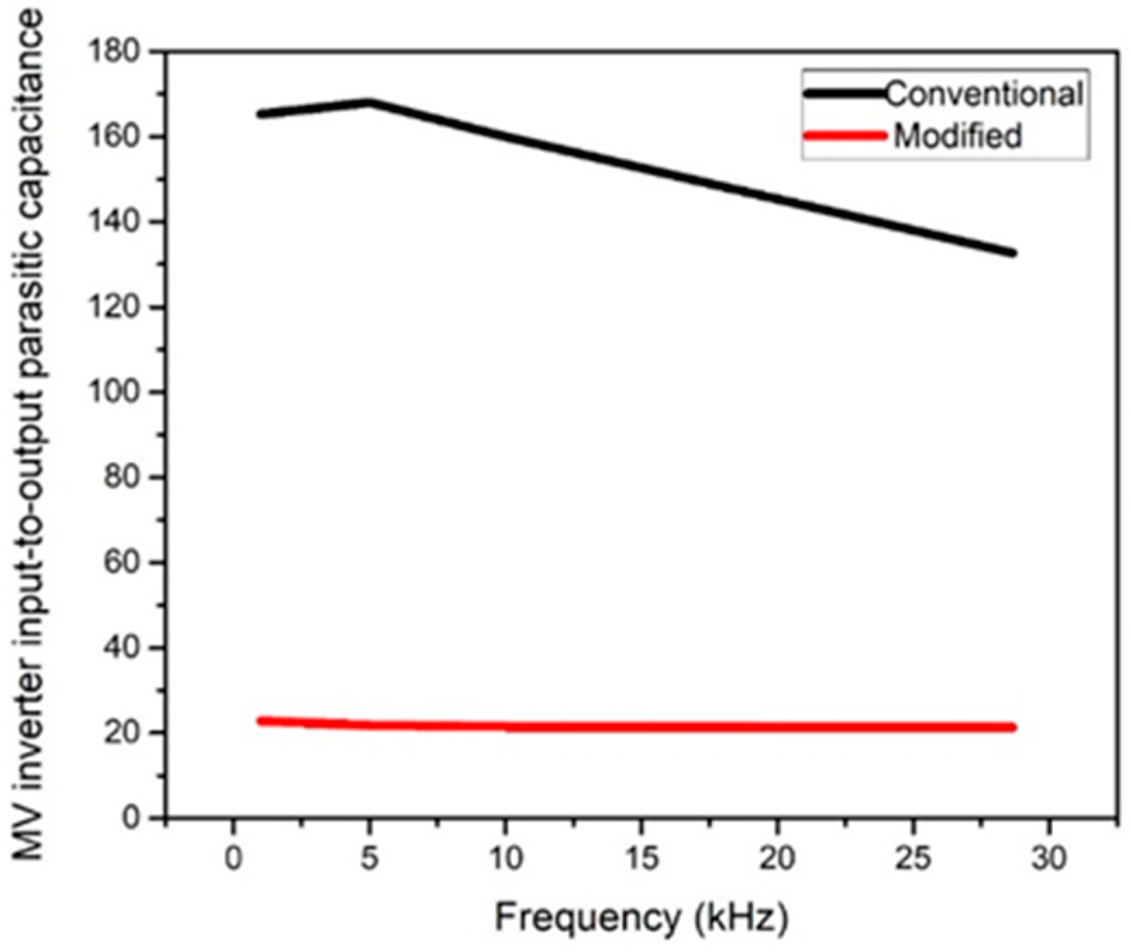
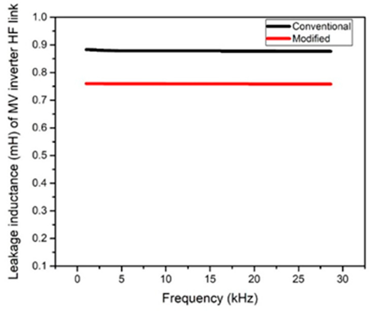
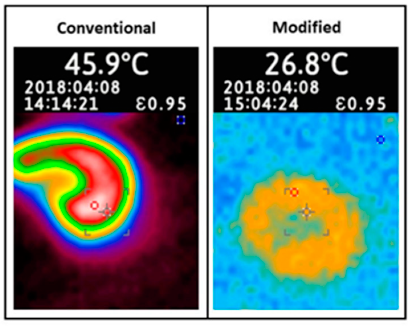
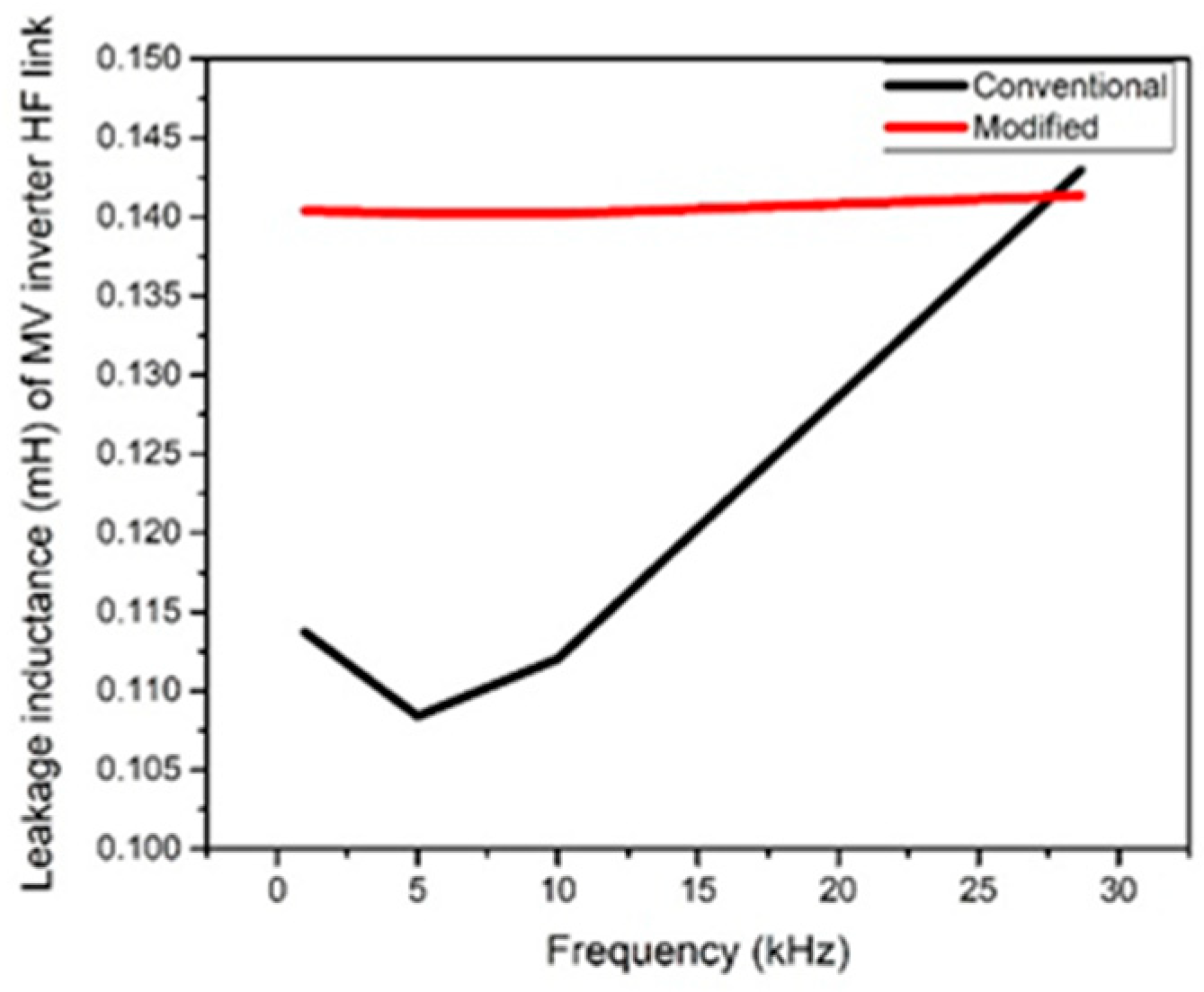
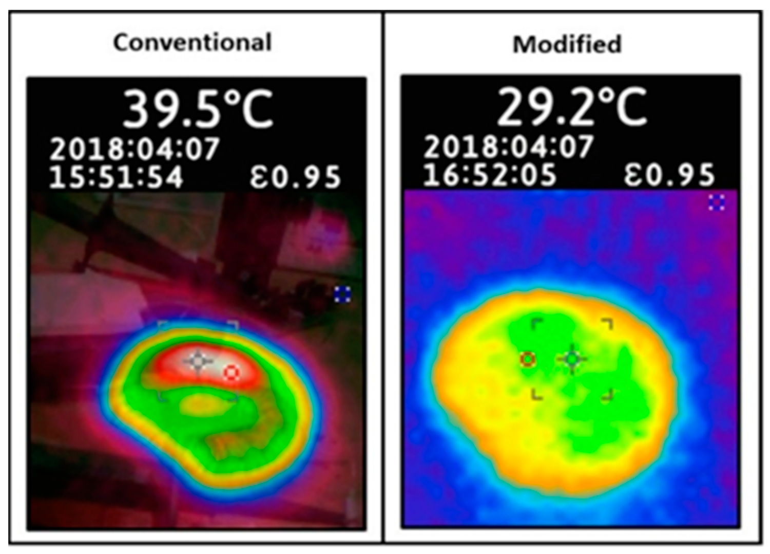
6.1. Toroidal Transformer with 180° Sectored Winding

Inter-winding Capacitance: Large inter-winding capacitance causes a significant amount of common mode noise at high-frequency operations. Figure 11 shows the comparison for parasitic capacitance from 1 to 30 kHz frequency at a high-frequency-based MV inverter. It is clearly visible that the proposed modified design has minimized the parasitic capacitance close to 20 pF, which is much lower than the conventional design. This was because of the mold, which helped increase the distance between the windings.
Leakage Inductance: In a sectored wound transformer, when the winding covers only 180°, leakage flux path changes in the core. According to theory, we expected the leakage inductance to be higher in modified design when compared with the conventional design because of the distance between windings created by the PLA mold. However, the 3D printed mold using PLA filament was mounted over the ferrite toroid core and secondary windings to completely encapsulate them and provided scope to increase the mean length turn of the primary winding, which is required to reduce the leakage inductance. This theory is supported by the experiment results [37]. Figure 12 demonstrates that the modified design recorded less leakage inductance than the conventional design.
Temperature: By comparing modified and conventional transformers on full load, it is clearly visible that lowering the interwinding capacitance and harmonics distortion helped significantly in controlling the temperature rise issue in the transformer (Figure 13).

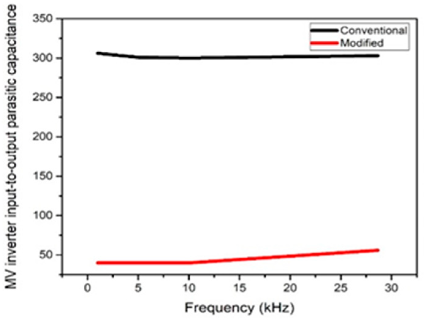
6.2. Toroidal Transformer with 360° Sectored Winding

The primary winding is on top of the secondary winding for the entire 360°, leakage flux is produced by the current in the windings, which are opposite in direction and equal in magnitude ( N 1 I 1 = N 2 I 2 ), thus magnetizing or leakage flux cancels itself in the core.
Inter-winding Capacitance: Larger values of self-capacitance of the transformer, which occur between primary and secondary windings, play a vital role in large primary current distortions. Self-capacitance value of the proposed modified transformer prototype has been largely reduced (40 pF) with the help of 3D designed cover, spaces between windings, and proposed different winding arrangements compared with the conventional prototype. In Figure 14, winding capacitance for both conventional and modified transformers were plotted. It is noted that the modified design succeeded in minimizing the transformer self-capacitance by approximately 87% compared with conventional designs.
Leakage Inductance: The leakage inductance and primary/secondary capacitance are mutually exclusive and are governed by the distance between the windings and unwounded core. Therefore, it is difficult to achieve both low capacitive coupling and a high degree of inductive coupling in a power transformer. However, the magnetic core geometry and winding arrangements have a large influence on self-capacitance and leakage inductance of the transformer and because of the addition of a mold, it enables access to various types of winding arrangements. Thus, the modified design has successfully lowered the inter-winding capacitance and achieves the minimum difference between leakage inductance. The experimental results are shown in Figure 15.
Temperature: Modified design shows significant control in temperature rise by lowering the inter-winding capacitance and controlled leakage inductance over conventional designs (Figure 16).
An MV inverter high-frequency link-modified toroid transformer was designed differently from the conventional toroid designs. Both modified prototypes, case 2 and 4, showed extremely low coupling capacitance, that is, 20 pF and 40 pF, respectively. The toroidal transformer at 180° sectored winding has registered higher leakage inductance, which can be utilized in other topologies, such as dual active bridge topologies. The experimental results matched the calculated analysis quite well. Thus, the feasibility of the converter was validated.

7. Conclusions

Overall, the MV inverter with the proposed modified transformer design has a minimized total circuit input–output capacitance to approximately 20 pF, while the temperature increase was kept below 29.5 °C, without using any extra circuitry or cooling agent. The modified design is certainly a powerful solution to reduce the distortion in the waveform. This leads to an improved power quality of renewable power sources and an increase in the operational lifetime of the devices and loads involved in power systems. Hence, the MV inverter with the modified design transformer is more robust than other available power inverters of the same power rate. These experimental measurements, which agree with the mathematical derivation, prove that the transformer shape and winding arrangements have a huge impact on the inter-winding capacitance, and cannot be ignored in power inverters when power quality improvement is of concern.
Finally, the overall result achieved with the prototype provides a very high resistance to the common mode noise current caused by rapid voltage transients, which makes the MV inverter feasible for renewable energy sources applications. For future research, a study of the optimal design method on advanced prototypes with higher inductive coupling with more controlled THD will be conducted.

Author Contributions

H.-J.K., G.S.P., H.S., and H. conceptualized the idea of this research project. H.-J.K. and G.S.P. developed the proposal to the funding body. Finally, the project was awarded the funding. H., P.S., and H.S. discuss the design for the MV inverter high-frequency toroid transformer. H. and H.Y.L. developed the 3D design model including material selection. The fabrication and integration of the experimental setup were mostly carried out by the H., M.A.K. and M.U.A., under the supervision of H.J.K. and G.S.P. Mathematics derivation and real-time data was analyzed by H.S. and H. The paper was written by H. and H.J.K.

Funding

This research was supported by Basic Research Laboratory through the National Research Foundations of Korea. Funded by the Ministry of Science, ICT, and Future Planning (NRF-2015R1A4A1041584).

Conflicts of Interest

The authors declare no conflict of interest.

References

  1. Gu, W.J.; Liu, R. A study of volume and weight vs. frequency for high-frequency transformers. In Proceedings of the IEEE Power Electronics Specialist Conference (PESC 1993), Seattle, WA, USA, 20–24 June 1993; pp. 1123–1129. [Google Scholar]
  2. Leibl, M.; Ortiz, G.; Kolar, J.W. Design and experimental analysis of a medium-frequency transformer for solid-state transformer applications. IEEE J. Emerg. Sel. Top. Power Electron. 2017, 5, 110–123. [Google Scholar] [CrossRef]
  3. Kulkarni, A.; John, V. New start-up scheme for HF transformer link photovoltaic inverter. IEEE Trans. Ind. Appl. 2017, 53, 232–241. [Google Scholar] [CrossRef]
  4. Basu, K.; Mohan, N. A high-frequency link single-stage PWM inverter with common-mode voltage suppression and source-based commutation of leakage energy. IEEE Trans. Power Electron. 2014, 29, 3907–3918. [Google Scholar] [CrossRef]
  5. De, D.; Ramanarayanan, V. A proportional $bm +$ multiresonant controller for three-phase four-wire high-frequency link inverter. IEEE Trans. Power Electron. 2010, 25, 899–906. [Google Scholar] [CrossRef]
  6. Hayashi, Y.; Matsugaki, Y.; Ninomiya, T. Design Consideration for High Step-up Nonisolated Multicellular dc-dc Converter for PV Micro Converters. Available online: https://www.hindawi.com/journals/je/2018/5098083/ (accessed on 11 June 2018).
  7. Kouro, S.; Leon, J.I.; Vinnikov, D.; Franquelo, L.G. Grid-connected photovoltaic systems: an overview of recent research and emerging PV converter technology. IEEE Ind. Electron. Mag. 2015, 9, 47–61. [Google Scholar] [CrossRef]
  8. Sathishkumar, P.; Krishna, T.N.V.; Himanshu; Khan, M.A.; Zeb, K.; Kim, H.-J. Digital soft start implementation for minimizing start up transients in high power DAB-IBDC converter. Energies 2018, 11, 956. [Google Scholar] [CrossRef]
  9. Alexander, S. Development of solar photovoltaic inverter with reduced harmonic distortions suitable for Indian sub-continent. Renew. Sustain. Energy Rev. 2016, 56, 694–704. [Google Scholar] [CrossRef]
  10. Sathishkumar, P.; Himanshu; Piao, S.; Khan, M.A.; Kim, D.-H.; Kim, M.-S.; Jeong, D.-K.; Lee, C.; Kim, H.-J. A blended SPS-ESPS control DAB-IBDC converter for a standalone solar power system. Energies 2017, 10, 1431. [Google Scholar] [CrossRef]
  11. Singh, R.; Taghizadeh, S.; Tan, N.M.L.; Pasupuleti, J. Battery energy storage system for PV output power leveling. J. Eng. 2018, 2018, 5098083. Available online: https://www.hindawi.com/journals/ape/2014/796708/ (accessed on 11 June 2018). [CrossRef]
  12. Bolduc, P.; Lehmicke, D.; Smith, J. Performance of a grid-connected PV system with energy storage. In Proceedings of the 23th IEEE Photovoltaic Specialists Conference (Cat. No.93CH3283-9), Louisville, KY, USA, 10–14 May 1993; pp. 1159–1162. [Google Scholar]
  13. Tan, N.M.L.; Abe, T.; Akagi, H. Design and performance of a bidirectional isolated DC–DC converter for a battery energy storage system. IEEE Trans. Power Electron. 2012, 27, 1237–1248. [Google Scholar] [CrossRef]
  14. McBee, K.D. Transformer aging due to high penetrations of PV, EV charging, and energy storage applications. In Proceedings of the 2017 Ninth Annual IEEE Green Technologies Conference (GreenTech), Denver, CO, USA, 29–31 March 2017; pp. 163–170. [Google Scholar]
  15. Bojoi, R.I.; Limongi, L.R.; Roiu, D.; Tenconi, A. Enhanced power quality control strategy for single-phase inverters in distributed generation systems. IEEE Trans. Power Electron. 2011, 26, 798–806. [Google Scholar] [CrossRef]
  16. Eltawil, M.A.; Zhao, Z. Grid-connected photovoltaic power systems: Technical and potential problems—A review. Renew. Sustain. Energy Rev. 2010, 14, 112–129. [Google Scholar] [CrossRef]
  17. Popavath, L.N.; Kaliannan, P. Photovoltaic-STATCOM with Low Voltage Ride through Strategy and Power Quality Enhancement in a Grid Integrated Wind-PV System. Electronics 2018, 7, 51. [Google Scholar] [CrossRef]
  18. Real-Calvo, R.; Moreno-Munoz, A.; Gonzalez-De-La-Rosa, J.J.; Pallares-Lopez, V.; Gonzalez-Redondo, M.J.; Moreno-Garcia, I.M. An embedded system in smart inverters for power quality and safety functionality. Energies 2016, 9, 219. [Google Scholar] [CrossRef]
  19. Li, Y.; Oruganti, R. A flyback-CCM inverter scheme for photovoltaic AC module application. Aust. J. Electr. Electron. Eng. 2009, 6, 301–309. [Google Scholar] [CrossRef]
  20. Pairodamonchai, P.; Suwankawin, S.; Sangwongwanich, S. Design and implementation of a hybrid output EMI filter for high-frequency common-mode voltage compensation in PWM inverters. IEEE Trans. Ind. Appl. 2009, 45, 1647–1659. [Google Scholar] [CrossRef]
  21. Wang, F.; Duarte, J.L.; Hendrix, M.A.M.; Ribeiro, P.F. Modeling and analysis of grid harmonic distortion impact of aggregated DG inverters. IEEE Trans. Power Electron. 2011, 26, 786–797. [Google Scholar] [CrossRef]
  22. Grady, W.M.; Santoso, S. Understanding power system hannonics. IEEE Power Eng. Rev. 2001, 21, 8–11. [Google Scholar] [CrossRef]
  23. Abdi, B.; Ranjbar, A.H.; Farabi, V.; Yazdanparast, M.S. Effect of transformer’s parameters on harmonic generation. Energy Procedia 2011, 12, 679–685. [Google Scholar] [CrossRef]
  24. Murthy-Bellur, D.; Kazimierczuk, M.K. Winding losses caused by harmonics in high-frequency flyback transformers for pulse-width modulated dc-dc converters in discontinuous conduction mode. IET Power Electron. 2010, 3, 804–817. [Google Scholar] [CrossRef]
  25. Zolfaghari, A.; Chan, A.; Razavi, B. Stacked inductors and transformers in CMOS technology. IEEE J. Solid-State Circuits 2001, 36, 620–628. [Google Scholar] [CrossRef]
  26. Portolan, A.; Hofsajer, I.W. The analysis and design of an inter-winding shielding structure of a high frequency transformer. In Proceedings of the 2007 IEEE Power Engineering Society Conference and Exposition in Africa-PowerAfrica, Johannesburg, South Africa, 16–20 July 2007; pp. 1–6. [Google Scholar]
  27. Nguyen-Duy, K.; Ouyang, Z.; Knott, A.; Andersen, M.A.E. Minimization of the transformer inter-winding parasitic capacitance for modular stacking power supply applications. In Proceedings of the 2014 16th IEEE European Conference on Power Electronics and Applications, Lappeenranta, Finland, 26–28 August 2014; pp. 1–10. [Google Scholar]
  28. Ali, M.U.; Nengroo, S.H.; Khan, M.A.; Zeb, K.; Kamran, M.A.; Kim, H.J. A real-time simulink interfaced fast-charging methodology of lithium-ion batteries under temperature feedback with fuzzy logic control. Energies 2018, 11, 1122. [Google Scholar]
  29. Ajami, A.; Farakhor, A.; Ardi, H. Minimisations of total harmonic distortion in cascaded transformers multilevel inverter by modifying turn ratios of the transformers and input voltage regulation. IET Power Electron. 2014, 7, 2687–2694. [Google Scholar] [CrossRef]
  30. Kashyap, M.; Kansal, S. Temperature control in transformer using intelligent system. In Proceedings of the 2015 2nd IEEE International Conference on Recent Advances in Engineering Computational Sciences (RAECS), Chandigarh, India, 21–22 December 2015; pp. 1–6. [Google Scholar]
  31. Hurezeanu, I.; Nicola, C.I.; Sacerdoţianu, D.; Nicola, M.; Aciu, A.M.; Niţu, M.C. Temperature control and monitoring system for power transformer windings using fiber optic sensors. In Proceedings of the 2016 IEEE International Symposium on Fundamentals of Electrical Engineering (ISFEE), Bucharest, Romania, 30 June–2 July 2016; pp. 1–4. [Google Scholar]
  32. Blache, F.; Keradec, J.P.; Cogitore, B. Stray capacitances of two winding transformers: equivalent circuit, measurements, calculation and lowering. In Proceedings of the 1994 IEEE Industry Applications Society Annual Meeting, Denver, CO, USA, 2–6 October 1994; pp. 1211–1217. [Google Scholar]
  33. Conway, D.W. Shielded Electrical Wire Construction, and Transformer Utilizing the same for Reduction of Capacitive Coupling. U.S. Patent 5,012,125, 30 April 1991. [Google Scholar]
  34. De León, F.; Purushothaman, S.; Qaseer, L. Leakage inductance design of toroidal transformers by sector winding. IEEE Trans. Power Electron. 2014, 29, 473–480. [Google Scholar] [CrossRef]
  35. Mathew, A.P.; Oksman, K.; Sain, M. Mechanical properties of biodegradable composites from poly lactic acid (PLA) and microcrystalline cellulose (MCC). J. Appl. Polym. Sci. 2005, 97, 2014–2025. [Google Scholar] [CrossRef] [Green Version]
  36. Silverajah, V.S.G.; Ibrahim, N.A.; Zainuddin, N.; Yunus, W.M.Z.W.; Hassan, H.A. Mechanical, thermal and morphological properties of poly (lactic acid)/epoxidized palm olein blend. Molecules 2012, 17, 11729–11747. [Google Scholar] [CrossRef] [PubMed]
  37. Mclyman, C.W. Transformer and Inductor Design Handbook; CRC Press: Boca Raton, FL, USA, 2004; Available online: https://www.taylorfrancis.com/books/9780203913598 (accessed on 31 March 2004).
Figure 1. Renewable energy source on and off grid system.
Electronics 07 00142 g001
Figure 2. Ferrite 77 material core dimensions (courtesy: Fair-Rite products Corp).
Electronics 07 00142 g002
Figure 3. Temperature effects on Ferrite 77 material properties (courtesy: Fair-Rite products Corp).
Electronics 07 00142 g003
Figure 4. Circuit layout for photovoltaic (PV) high-frequency-based medium voltage (MV) inverter system.
Electronics 07 00142 g004
Figure 5. The 180° conventional (A) flux pattern in core; (B) 2D model; (C) 3D model.
Electronics 07 00142 g005
Figure 6. The 180° modified (A) flux pattern in core; (B) 2D model; (C) 3D model.
Electronics 07 00142 g006
Figure 7. The 360° conventional (A) 2D model; (B) flux distribution; (C) 3D model.
Electronics 07 00142 g007
Figure 8. The 360° modified (A) 2D model; (B) flux distribution; (C) 3D model.
Electronics 07 00142 g008
Figure 9. Toroidal transformer with 180° sectored winding, Conceptual presentation of transformer prototypes from left to right conventional and modified. PLA—polylactic acid.
Electronics 07 00142 g009
Figure 10. Block diagram for the testing process for prototypes PV high frequency based MV inverter systems. THD—total harmonics distortion.
Electronics 07 00142 g010
Figure 11. Toroidal transformers at 180° sectored winding, parasitic coupling capacitance comparison between the conventional and modified design of high-frequency link based MV inverter systems.
Electronics 07 00142 g011
Figure 12. Toroidal transformers at 180° sectored winding, leakage inductance comparison between the conventional and modified design of high-frequency link based MV inverter systems.
Electronics 07 00142 g012
Figure 13. Toroidal transformers at 180° sectored winding, temperature comparison between the conventional and modified transformer design.
Electronics 07 00142 g013
Figure 14. Toroidal transformers at 360° sectored winding, parasitic coupling capacitance comparison between the conventional and modified design of high-frequency link based MV inverter systems.
Electronics 07 00142 g014
Figure 15. Toroidal transformers at 360° sectored winding, leakage inductance comparison of modified and conventional design of high-frequency link-based MV inverter systems.
Electronics 07 00142 g015
Figure 16. Toroidal transformers at 360° sectored winding, temperature comparison between the conventional and modified design of high-frequency link-based MV inverter systems.
Electronics 07 00142 g016
Table 1. Ferrite 77 toroid core dimensions (courtesy: Fair-Rite products Corp).
DimmmMm tolNominal
A61.00±1.302.400
B35.55±0.851.400
C12.70±0.500.500
Table 2. Ferrite 77 toroid core electrical properties (courtesy: Fair-Rite products Corp).
Electrical Properties
AL (nH)2950 ± 25%
AE (cm2)1.58000
∑I/A (cm−1)9.20
Ie (cm)14.50
Ve (cm3)22.80000
Table 3. Current and Voltage total harmonic distortion allowing values and their associated risks (courtesy: Interpreting European norm (EN) 50160 and International Electrotechnical Commission (IEC) standard 61727). THD—total harmonics distortion.
THDVTHDIRisk
<8%<5%normal situation considerable
8–15%5–50%Minor harmonic pollution with malfunctions possibility
>15%>50%major harmonic pollution with malfunctions probability
Table 4. Detailed parameters of the transformer prototypes. PLA—polylactic acid.
Prototypes Physical PropertiesCase 1Case 2Case 3Case 4
Copper Wire standard24 AWG24 AWG24 AWG24 AWG
Primary Turns116116220220
Secondary Turns116116220220
Core Material (Table 1) Ferrite 77Ferrite 77Ferrite77Ferrite 77
Core shapeRingRingRingRing
Permittivity (F/m)8.85 × 10−12 (Air)8.4190×10⁻¹² (Air + PLA)8.85×10⁻¹² (Air)8.419 × 10⁻¹² (Air + PLA)
Inner Radius (mm)17.77515.27517.77515.275
Outer Radius (mm)30.532.530.532.5
Primary Voltage (V)24242424
Secondary Voltage (V)~24~24~24~24
Frequency (kHz)1–301–301–301–30
r 1 17.26514.76516.75514.765
r 2 30.532.531.0132.5
r 3 17.26517.26517.26517.265
r 4 30.530.530.530.5
Table 5. Theoratical analysis of all presented prototypes, calculated energy, and inter-winding capacitance.
Case 1
E1E2E3E4EtotalCapacitanceeq (F)
Energy (J)5.63 × 10−103.87 × 10−103.54 × 10−102.87 × 10−101.59 × 10−102.76 × 10⁻¹²
Percentage %35.424.322.318100
Case 2
E1E2E3E4EtotalCapacitanceeq (F)
Energy (J)5.31 × 10−103.74 × 10−103.66 × 10−102.94 × 10−101.57 × 10−92.72 × 10−12
Percentage %33.923.923.418.8100
Case 3
E1E2E3E4EtotalCapacitanceeq (F)
Energy (J)5.69 × 10−103.87 × 10−103.56 × 10−102.90 × 10−101.60 × 10−92.78 × 10−12
Percentage %35.524.222.218.1100
Case 4
E1E2E3E4EtotalCapacitanceeq (F)
Energy (J)5.29 × 10−103.73 × 10−103.73 × 10−103.00 × 10−101.57 × 10−92.73 × 10−12
Percentage %33.623.723.719100
Table 6. Voltage and current THD for all prototypes.
Source Input Voltage (V)CaseTHDV %THDI %
PrimarySecondaryPrimarySecondary
24145.5322.345.67.20
24234.7022.1512.2211.85
24311.9216.3348.1949.56
2449.8114.9443.0644.32

