Article

Photovoltaic-STATCOM with Low Voltage Ride through Strategy and Power Quality Enhancement in a Grid Integrated Wind-PV System

by
Lakshman Naik Popavath
* and
Palanisamy Kaliannan
School of Electrical Engineering, VIT University, Vellore-632014, India
*
Author to whom correspondence should be addressed.
Electronics 2018, 7(4), 51; https://doi.org/10.3390/electronics7040051
Submission received: 5 March 2018 / Revised: 7 April 2018 / Accepted: 7 April 2018 / Published: 12 April 2018
(This article belongs to the Special Issue Grid Connected Photovoltaic Systems)

Abstract

:
The traditional configurations of power systems are changing due to the greater penetration of renewable energy sources (solar and wind), resulting in reliability issues. At present, the most severe power quality problems in distribution systems are current harmonics, reactive power demands, and the islanding of renewables caused by severe voltage variations (voltage sag and swell). Current harmonics and voltage sag strongly affect the performance of renewable-based power systems. Various conventional methods (passive filters, capacitor bank, and UPS) are not able to mitigate harmonics and voltage sag completely. Based on several studies, custom power devices can mitigate harmonics completely and slightly mitigate voltage sags with reactive power supplies. To ensure the generating units remain grid-connected during voltage sags and to improve system operation during abnormal conditions, efficient and reliable utilization of PV solar farm inverter as STATCOMs is needed. This paper elaborates the dynamic performance of a VSC-based PV-STATCOM for power quality enhancement in a grid integrated system and low voltage ride through (LVRT) capability. LVRT requirements suggest that the injection of real and reactive power supports grid voltage during abnormal grid conditions. The proposed strategy was demonstrated with MATLAB simulations.

1. Introduction

At present, the increased utilization of non-linear loads and greater penetration of renewable energy sources is contributing to power quality problems, such as current harmonics, reactive power demands and voltage variations (voltage sag and swell), in distribution and transmission systems. Among the various power quality issues, harmonics and voltage sag are the most common and severe issues in power systems [1]. The main cause of harmonics is the increased use of power electronic-based electrical appliance controls to improve their performance. The main causes of voltage sag are the escalation of load current caused by the starting of large motors, transformer energization, switch ON and OFF operation of circuit breakers, faults within the customer’s facility, equipment failure, abnormal weather conditions (lightning strikes on power systems) and the highly intermittent nature of renewable sources connected to distribution systems [1,2]. As per IEEE Std. 1159, voltage sag is defined as the reduction in RMS (Root Mean Square) voltage (AC voltage) from 90% to 10% of the nominal voltage at power frequencies within 0.5 cycles to 1 min [3,4]. Voltage sags are classified based on magnitude and sag duration. Voltage sag contributes to over 80% of the power quality concerns that exist in distribution and transmission systems [5].
The most important characteristics of voltage sags are voltage magnitude/depth and sag duration. Harmonics and voltage sags affect the dynamic performance of sensitive equipment, such as robotics, Adjustable Speed Drives (ASD), high intensity discharging lamps, and PLC.
The various conventional methods (passive filters, capacitor bank parallel feeder, and UPS) employed to mitigate harmonics and voltage sags are not able to mitigate these issues completely. Based on several research studies on active power filters, PV-STATCOM can mitigate harmonics and voltage sags and ensure energy sources remain grid-connected during abnormal conditions. This paper considers the active performance of PV-STATCOM for the mitigation of harmonics and voltage sags created in the proposed test model, with the help of an advanced control strategy.
Low voltage ride through (LVRT) indicates that all generating units should remain connected within a grid, continuously, to provide the required amount of real and reactive power (Q) to support grid voltage recovery during a sag [6,7,8]. Figure 1 depicts the voltage profiles that generating units must sustain according to various grid codes [9]. The injection demands of reactive power during sags to support grid stability that is required by the German Grid Code, the Italian Grid Code, and the Japanese Grid code [9,10,11], are shown in Figure 2. LVRT strategy can prevent inverter over-current and provide reactive power support for sag mitigation [7,9]. The various grid standards are mainly focused on power quality issues, frequency stability and voltage stability [10,11]. It is required that generating units should cease to energize local loads during a grid fault, for example voltage sag or frequency disturbance, which is known as anti-islanding protection [10,11]. In normal operating conditions, PV-STATCOM will inject the reactive power that is demanded by the load on the grid integrated system; whereas, in abnormal operating conditions (i.e., grid fault conditions) as per the LVRT requirement, the shunt connected Voltage Source Converter (VSC)-based PV-STATCOM will inject reactive power to the grid, in addition to the reactive power demanded by the load and wind generators.
This article is organized as follows. We will give an overview of voltage sag mitigation and the operation principle of a proposed control strategy for PV-STATCOM. The analysis, results, and conclusions will be presented in Section 2, Section 3, Section 4 and Section 5, respectively.

2. Voltage Sag Mitigation

This section mainly discusses the alignment of the test model and the dynamic performance of PV-STATCOM for the mitigation of voltage sag in a grid integrated system. A Voltage Source Converter (VSC)-based PV-STATCOM was connected in shunt for the injection of the required active and reactive power to provide support for grid voltage recovery, in addition to harmonics compensation [7]. A non-linear load was supplied by both the main grid source and the wind farm, as shown in Figure 3.
The shunt active filter was supplied by the photovoltaic (PV) system for the mitigation of harmonics and voltage sag at the Point of Common Coupling (PCC) in the grid-integrated Wind-PV system.

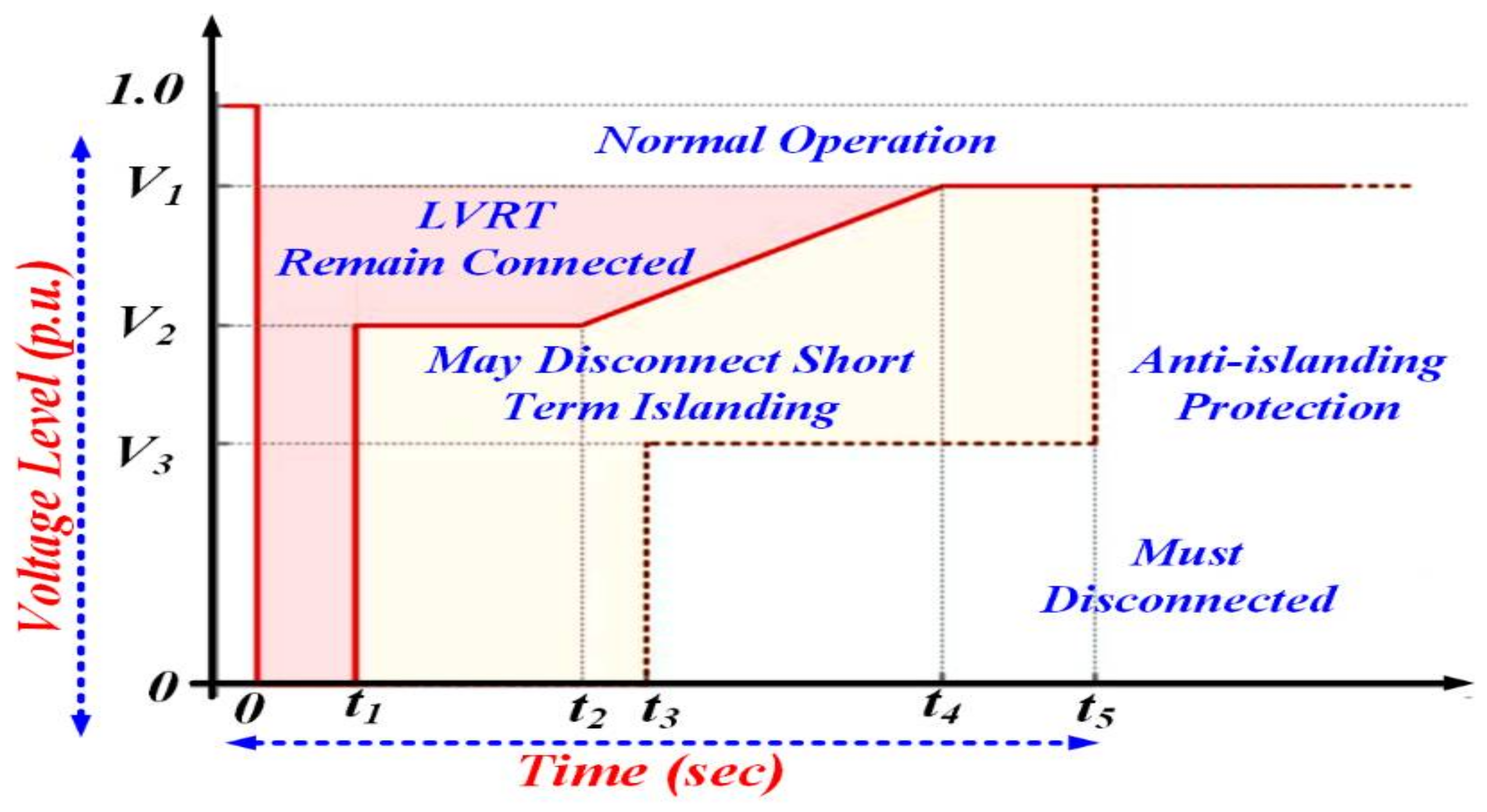
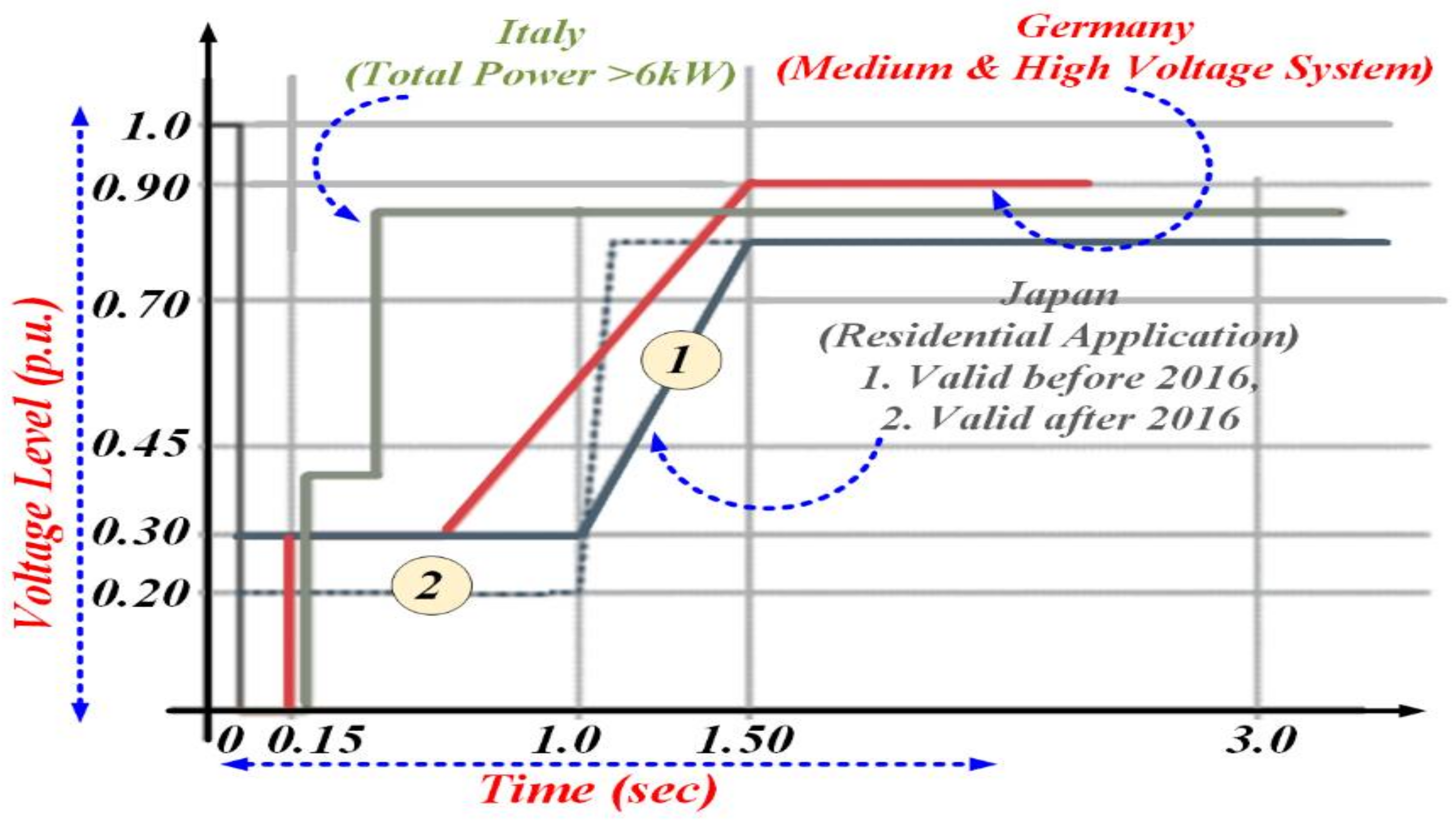
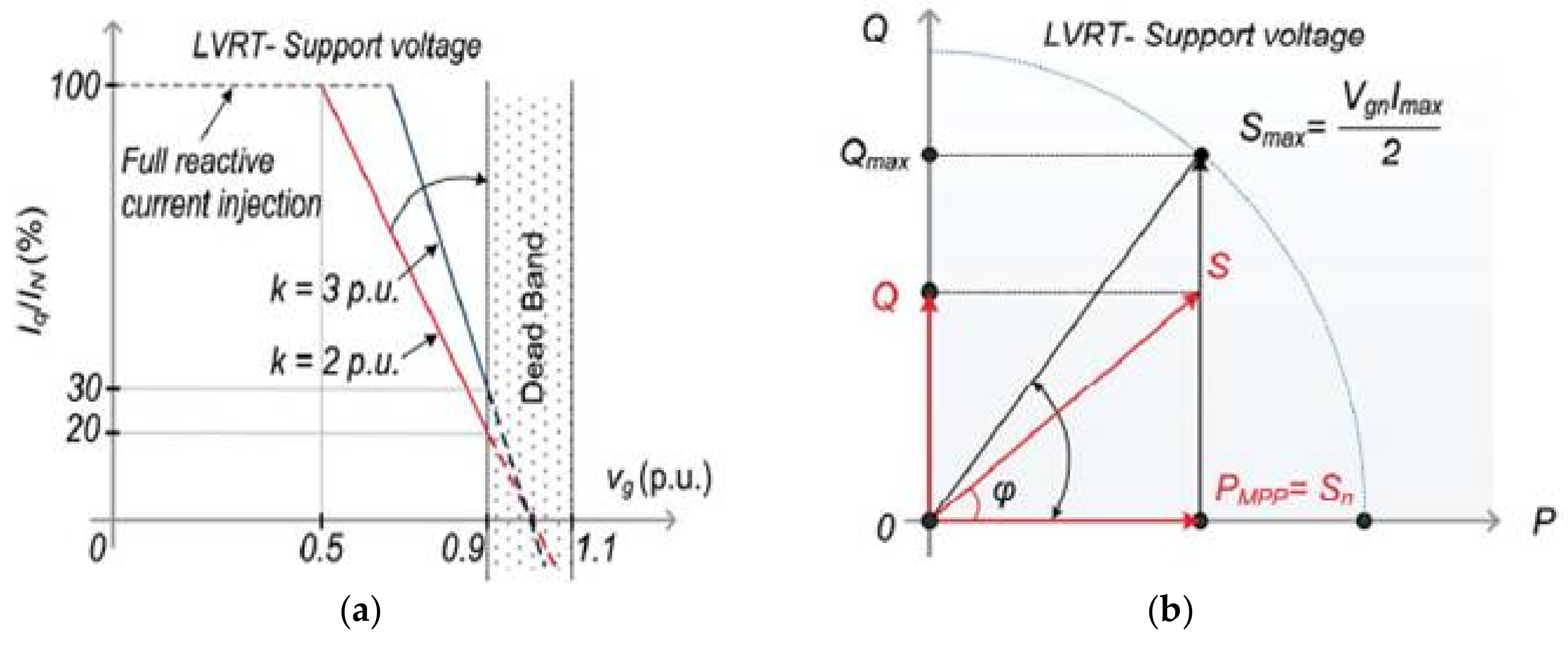
2.1. LVRT Requirements in the Grid Codes

Voltage sag is one of the most severe power quality issues among all power quality issues in electrical distribution and transmission systems. Generally, voltage sags are caused by faults (short-circuits) within a system [3,5,6]. As per various international standards, a voltage sag is mainly characterized by its magnitude and duration [6]. Low Voltage Ride Through (LVRT) technology gives robust support to the power grid for grid voltage recovery under abnormal conditions [7,12,13,14,15]. LVRT requirements in grid codes suggest that all generating units must remain connected with the grid to provide stable operation during the sag, even if, in some cases, the voltage value is reduced to zero at PCC [7]. This requirement is known as LVRT.

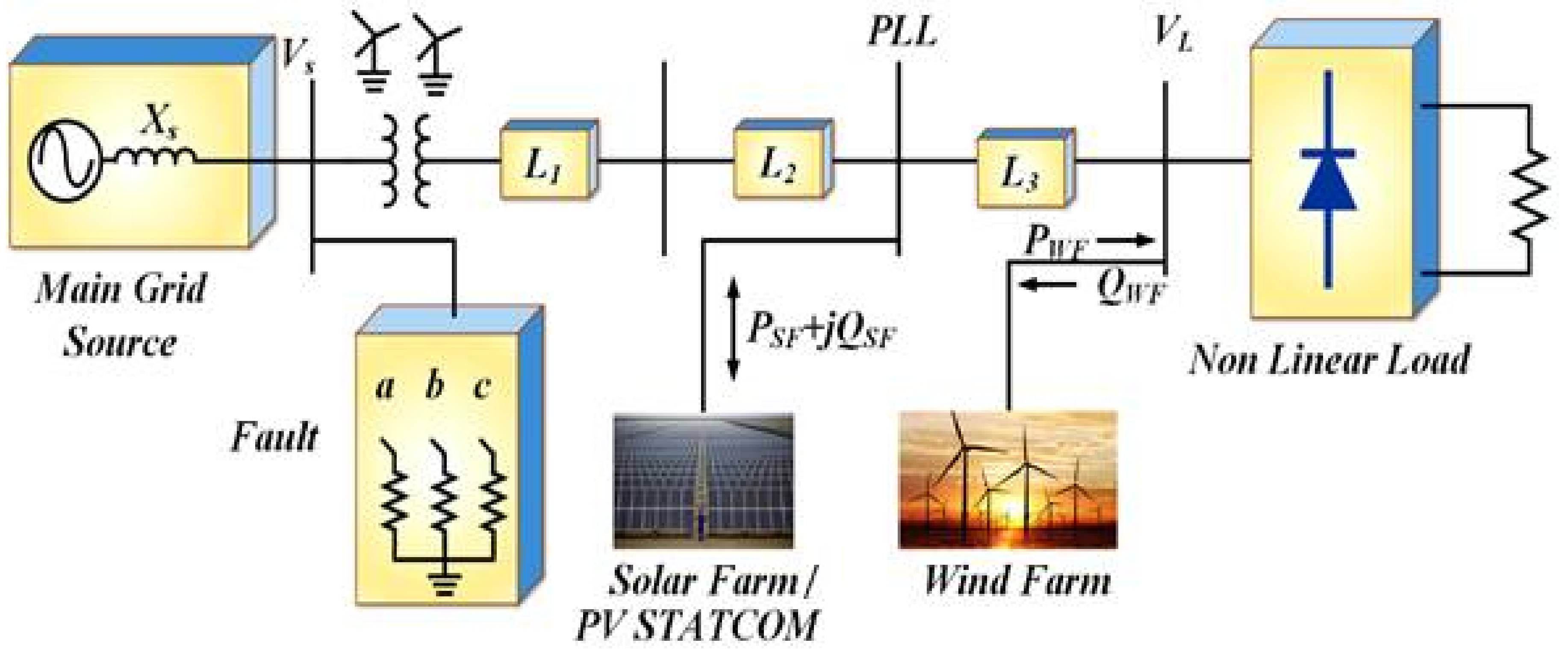
2.2. VSC-Based PV-STATCOM

PV-STATCOM has typically been used to manage reactive power and harmonics at the PCC in distribution networks for the mitigation of power quality issues. The photovoltaic (PV) solar system collects energy from sunlight and generates a direct current [16]. In the proposed test model, a Shunt Active Power Filter (SAPF) was configured from a solar PV inverter control. PV-STATCOM is a shunt connected 3-phase VSC that is actually meant for the evacuation of PV generated power [6,17]. It consists of a capacitor on the DC side and a small reactor on the AC side for filtration of the high frequency components injected by the Insulted Gate Bipolar Transistor (IGBT)-based VSC [17,18], as shown in Figure 4.
As per the LVRT requirements, the PV-STATCOM could supply reactive power to mitigate voltage sag by effectively utilizing the proposed control strategy. The active and reactive power management of PV-STATCOM could be determined by steady state equations, such as the following [6,19]:
P s = | V s | | V s t o | X s sin ( δ )
Q s = | V s | | V s t o | X s cos ( δ ) | V s 2 | X s
where P s and Q s are active and reactive powers, respectively, managed by PV-STATCOM. V s t is the voltage at the STATCOM terminals (see the STATCOM terminal voltages V s t a , V s t b , and V s t c in Figure 4), and V s is the system voltage. The voltage V s t o is the STATCOM output AC voltage at the PCC (see the STATCOM output AC voltages V s t o a , V s t o b , and V s t o c in Figure 4), X s is the reactance and δ is the phase difference between both voltages.

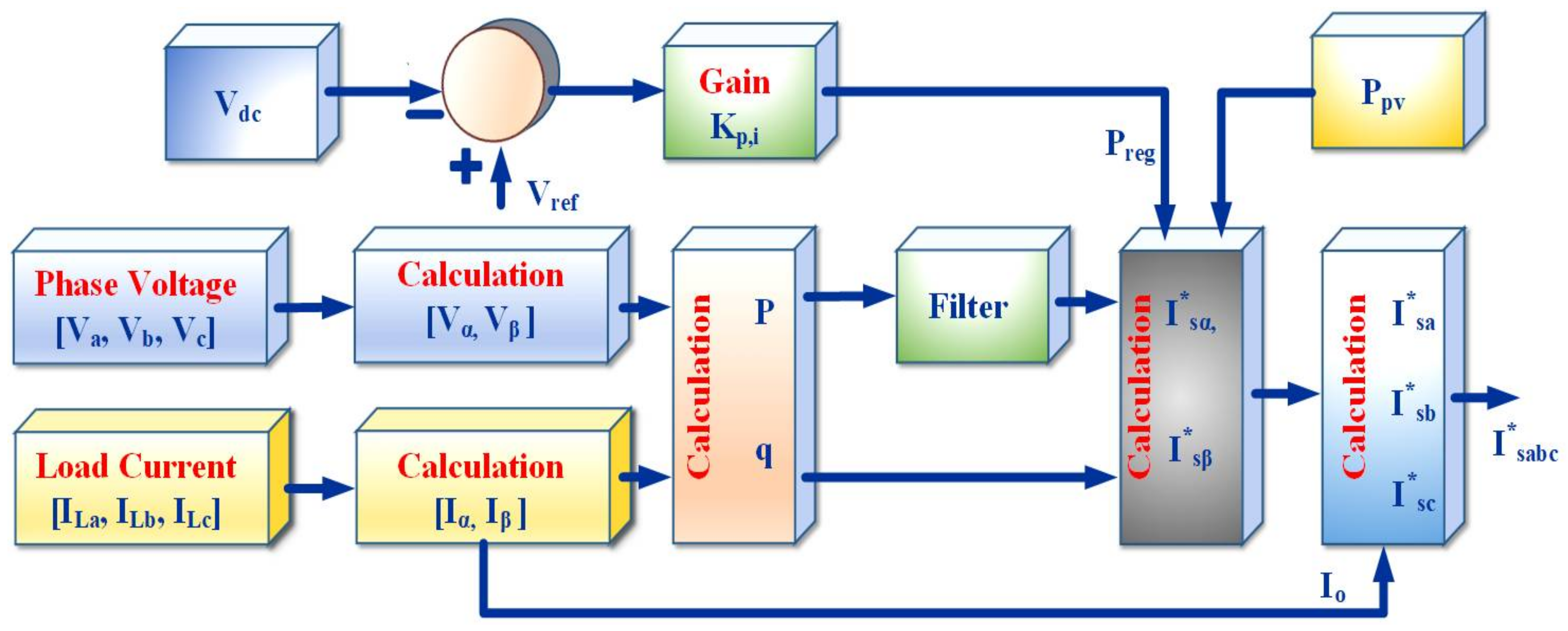
3. Control Strategy for PV-STATCOM

To meet the LVRT requirements, the proposed control strategy was designed to inject the real power and the required reactive power to enhance of power quality in the grid integrated system [20,21,22,23,24]. As per the various grid standards, the present controller was the pivotal part of this test model used to meet the Low Voltage Ride Through (LVRT) requirement for the mitigation of harmonics and voltage sag. The P-Q control strategy (instantaneous reactive power theory) is a time domain-controlled strategy valid for both steady state and transient state system conditions [12,25].

3.1. Grid Voltages and Currents

It is very important to analyse the grid voltages and currents for the mitigation of harmonics and voltage sag, as per the LVRT requirements. With the help of the Clarke transformation, the 3-phase voltage and currents were transformed to α β 0 ( abc α β 0 ) . The grid voltages and currents were given as follows:
V a = V m S i n ( ω t )
V b = V m S i n ( ω t 2 π 3 )
V c = V m S i n ( ω t 4 π 3 )
The instantaneous load currents were:
i L a = I L a n S i n { n ( ω t ) θ a n }
i L b = I L b n S i n { n ( ω t 2 π 3 ) θ b n }
i L c = I L c n S i n { n ( ω t 4 π 3 ) θ c n }
The stationary frame representations of the grid voltages and currents were expressed as per a Clarke transformation ( abc α β 0 ) , as follows:
[ V α V β ] = 2 3   [ 1 0   1 / 2 3 / 2   1 / 2 3 / 2 ] [ V a V b V c ]
[ i α i β ] = 2 3   [ 1 0   1 / 2 3 / 2   1 / 2 3 / 2 ] [ i L a i L b i L c ]
The active and reactive powers were calculated as:
p = v α i α + v β i β
q = v β i α + v α i β
The instantaneous real and reactive powers included AC and DC components, such as:
p = p ¯ + p ˜ ,   q = q ¯ + q ˜
where p ¯ and q ¯ were average active and reactive power, respectively, and p ˜ and q ˜ were the corresponding AC components, including harmonics.
[ i s α * i s β * ] = 1 Δ [ v α v β v β v α ] [ p ˜ + p r e g + p p v q ]
The powers p r e g and p p v could be computed as:
p r e g = k p ( V d c * V d c ) + k i ( V d c * V d c ) d v
P P V = V d c * I P V
where Δ = v α 2 + v β 2 ,   V d c is the voltage across the DC capacitor, and I P V is the solar PV output current. The reactive power during normal voltage is q   =   q L (reactive power required by the load) VAR, and during voltage sag (Grid faults) is q = q L + q L V R T VAR. As per the inverse Clarke transformation technique, the reference currents for activation of VSC-based PV-STATCOM was calculated as follows:
[ i s a * i s b * i s c *   ] = 2 3 [ 1 / 2 1 0 1 / 2 1 / 2 3 / 2 1 / 2 1 / 2 3 / 2 ] [ i 0 *   i s α *   i s β *   ]
where the subscripts α and   β denote the stationary reference frame axes.

3.2. Real and Reactive Power Control

Various standard grid codes recommend real and reactive power injection during LVRT operation, based on the PCC voltage magnitude. The instantaneous reactive power control method can develop power in stationary reference frames ( α β -Frame). Reactive power injection (RPI) control can be implemented by setting the active power ( p ) and the reactive power ( q ), followed by generating the reference grid current ( i s a b c * ) [11]. The whole control block diagram for instantaneous reactive power theory (P-Q control theory) is depicted in Figure 5.
In normal operation mode, the PV-STATCOM active power ( p ) is at maximum and reactive power is decided by the load ( q = q L VAR); however, under abnormal conditions, the RPI control method is enabled and sufficient VAR power is injected by PV-STATCOM, as per standard grid codes, to meet the LVRT requirements [11], as shown in Figure 6a. During LVRT operation, the PV-STATCOM should inject the required reactive current according to the sag voltage level as per the following relationship:
k = ( I q I q 0 ) / I N ( 1 v g )   w h e n   I q < I N
where v g is the grid voltage, I N is the rated current, I q is the reactive current and I q 0 is the initial reactive current before the sag. During normal operation, the PV-STATCOM injects reactive power, i.e., ( I q 0 = i q L A), whereas in grid fault conditions, PV-STATCOM should inject the required reactive current. Note that as per grid codes, k should be greater than 2 p.u. (i.e., k 2 p.u.) for minimum reactive current injections [11,25]. For normal sag voltage (e.g., v g = 0.7 p.u.), PV-STATCOM injects a minimum reactive current I q (46% of I N ), whereas for severe voltage sags (e.g., v g = 0.3 p.u., i.e., v g < 0.5   p . u . ), PV-STATCOM injects full reactive power, as shown in Figure 6a, and the active power injection should be deactivated. The injected reactive power is controlled by the converter apparent power S m a x [11], as depicted in Figure 6b.
The reactive power injection by PV-STATCOM for different sag voltage levels is given as follows:
{ I q = I N ;   0 v g < ( 1 1 k ) p . u . I q = k   ( 1 v g ) I N ;   ( 1 1 k ) p . u v g < 0.9   p . u .
With the help of a RPI control strategy, the average active power is kept constant based on P-Q theory and per phase power is given as:
P =   1 2 v g I d
where Id is the active current. In the normal operation mode I d = I N 2 I q L 2 ; hence, q = q L VAR. During the LVRT condition with constant power (Constant-P) control, the average active power is given as:
P = k d P N = ( k d 2 ) v g n I N
where k d is the power derating factor, and v g n and I N are nominal values of the grid voltage and current, respectively. If the voltage sag is less than ( 1 1 k )   p.u., i.e., ( 0 v g < 0.5   p . u . ), then PV-STATCOM injects the full reactive power ( I q = I N ) and p = 0 watts. For sag voltage level v g : ( 1 1 k ) p . u .   v g   <   0.9   p . u . , the PV-STATCOM injects the required amount of reactive power to enhance the power quality in the grid integrated system. The system parameters and their specification for the proposed work are given in Table 1.

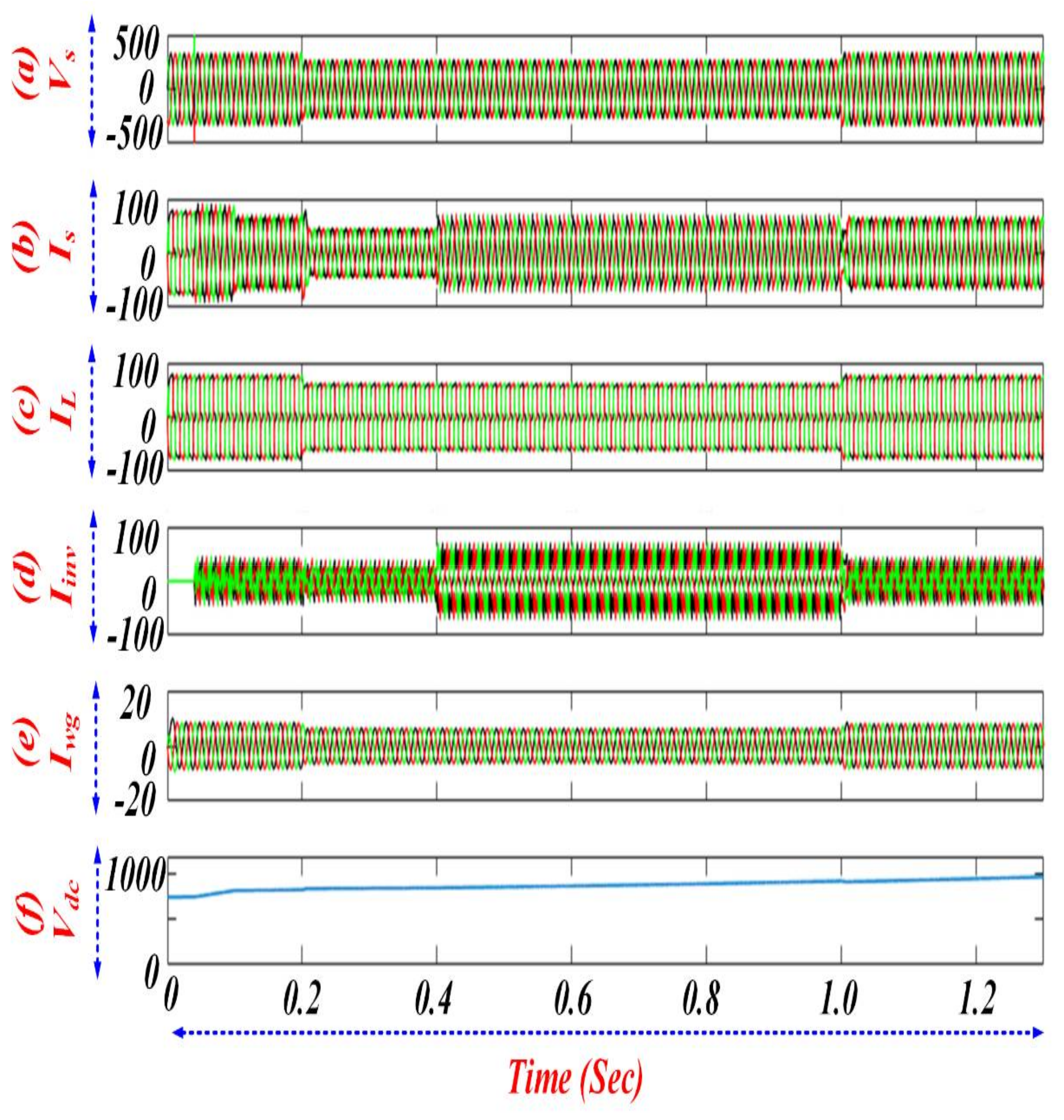
4. Result and Discussion

The MATLAB/Simulink-based proposed test model results depicted the active performance of a shunt connected PV-STATCOM for the mitigation of current harmonics and voltage sag. The test model also consisted of the non-linear load (3-phase uncontrolled rectifier supplying RL load) that was supplied by both the main grid and the wind generator. The gain values k p   (proportional gain) and k i (integral gain) were considered as 5 and 2.5, respectively, for the extraction of gate signals for the activation of electronic valves of VSC-based PV-STATCOM.
In the proposed test model, the voltage sag of 0.2 p.u. was created from 0.2 s to 1 s. Solar PV STATCOM was allowed to operate from 0.04 s to 2 s as a STATCOM, and from 0.1 s to 2 s, the PV module was connected. Reactive power was supplied based on the LVRT concept from 0.4 s to 1 s to support the grid. The proposed micro-grid was supplied by both the main grid and the wind generator. Figure 7a clearly shows that the source voltage was reduced from its normal value, from 0.2 s to 1 s (sag period), because of faults in the test model and voltage sag was mitigated by the PV-STATCOM. The current harmonics caused by the presence of non-linear loads was completely mitigated by the active filter from 0.04 s to 2 s. Before 0.04 s (STATCOM in the OFF condition), the harmonics were polluted the source current from its original nature, as shown in Figure 7b. Figure 7d shows the compensation action of PV-STATCOM, which injected the required amount of current at the desired phase and magnitude for the mitigation of harmonics. From Figure 7d, it is clear that during normal operation (from 0.04 s to 0.2 s and after 1 s), the PV-STATCOM injected the reactive current, 8.38 A, required by the load and wind generator i.e., ( I q 0 = i q L A), and during the abnormal condition, the PV-STATCOM injected the increased reactive current of 23.38 A to take care of the load, wind generator and grid i.e., ( I q = i q L + i q L V R T A), as per the LVRT requirement ( I q = I N ;   0 v g < ( 1 1 k ) p . u . ; I q = k   ( 1 v g ) I N ;   ( 1 1 k ) p . u v g < 0.9   p . u . ). Figure 7e shows that the wind generator supplied a current without any fluctuations. All the aforementioned compensation actions (mitigation of harmonics and voltage sag) occurred while keeping DC bus capacitor voltage constant ( V d c = 828   V ), as shown in Figure 7f.
Figure 8 demonstrates the active power injection and reactive power compensation by PV-STATCOM for the mitigation of power quality issues in the microgrid system. The Figure 8a clearly shows that, because of the faults, the main grid source was supplying less than the rated real power from 0.2 s to 1 s (sag period), i.e., the source active power was reduced from 41.4 kW to 17.88 kW. The test model consisted of reactive components, an induction generator and non-linear loads; thus, it had a reactive power demand of 15 kVAR. Figure 8b clearly shows that the reactive power was compensated by PV-STATCOM. To ensure the generating units remained grid-connected during the sag period and to keep the load power constant for stable operation, the PV-STATCOM injected both real and reactive powers from 0.04 s to 2 s (PV-STATCOM in the ON condition), as shown in Figure 8c. From Figure 8c, it is clear that during normal operation (i.e., from 0.04 s to 0.2 s and after 1 s), the PV-STATCOM injected the reactive power, 5.2 kVAR, that was required by the load and wind generator, i.e., ( q = q L VAR), and during the abnormal condition, the PV-STATCOM injected the required reactive power of 17.77 kVAR i.e., ( q = q L + q L V R T VAR), as per the LVRT requirement. During normal operation (before the voltage sag), the PV-STATCOM injected 7.4 kW of real power and 5.2 kVAR of reactive power. During abnormal conditions (from 0.2 s to 1 s of sag period), the PV-STATCOM injected reactive power of 17.77 kVAR (which was greater than the normal condition VAR power) for the mitigation of harmonics and voltage sag. Figure 8d shows the injected active and reactive powers by induction generator in the proposed microgrid system. The presented MATLAB simulation results reveal the performance of the VSC-based PV-STATCOM for the mitigation of harmonics and voltage sag in the proposed test model.

5. Conclusions

A novel PV-STATCOM Low Voltage Ride Through (LVRT) strategy, employed for the mitigation of current harmonics during normal operating conditions and for the mitigation of both current harmonics and voltage sag during grid faults in a grid integrated system, was presented in this article. The simulation results illustrated the power quality magnification in distribution systems. Power electronic-based (non-linear) loads are responsible for the creation of power quality issues, such as current harmonics, reactive power demand and voltage variations in distribution systems. With the active and efficient participation of a shunt-connected PV-STATCOM, the current harmonics and voltage sags were found to be completely mitigated in the test model. From the MATLAB simulation results, it is clear that the proposed P-Q control theory (instantaneous reactive power theory) was effectively utilized by PV-STATCOM for the injection of active and reactive power in a grid integrated system to keep load power constant and for the mitigation of current harmonics and voltage sag in the distribution system. The voltage at the Point of Common Coupling (PCC) was regulated by keeping DC capacitor voltage constant. The power factor was improved from lagging PF to Unity PF and the Total Harmonic Distortion (THD) value was reduced from 26.7% to 5.0%, which is within IEEE standards.

Acknowledgments

The authors would like to thank the Management of VIT University for providing an excellent research environment in which to complete this work.

Author Contributions

Lakshman Naik Popavath and Palanisamy Kaliannan both devised the model, undertook the data analysis and contributed to the writing of the manuscript.

Conflicts of Interest

The authors declare no conflict of interest.

References

  1. Manish, P.; Prabir, R.K. Voltage Sag Mitigation by D-STATCOM Using Voltage Regulation Technique. Int. J. Eng. Res. Technol. 2014, 3, 1–7. [Google Scholar]
  2. Ismail, N.; Wan Abdullah, W.N. Enhancement of Power Quality in Distribution System Using D-Statcom. In Proceedings of the 4th International Power Engineering and Optimization Conference (PEOCO2010), Shah Alam, Malaysia, 23–24 June 2010. [Google Scholar]
  3. Singh, S.; Rai, V.; Kumar, A.; Sahay, K.B. Simulation and comparison of DVR and D-STATCOM for voltage sag mitigation. In Proceedings of the 2016 IEEE 6th International Conference on Power Systems (ICPS), New Delhi, India, 4–6 March 2016; pp. 1–6. [Google Scholar]
  4. Dugan, R.C. Electrical Power Systems Quality, 2nd ed.; Professional Engineering; McGraw-Hill Companies: New York, NY, USA, 2004; pp. 1–525. [Google Scholar]
  5. Mariun, N.; Masdi, H.; Bashi, S.M.; Mohamed, A.; Yusuf, S. Design of a Prototype D-STATCOM Using DSP Controller for Voltage Sag Mitigation. In Proceedings of the 2006 IEEE Power India Conference, New Delhi, India, 10–12 April 2006; pp. 1–6. [Google Scholar]
  6. Obando-Montaño, A.F.; Carrillo, C.; Cidrás, J.; Díaz-Dorado, E. A STATCOM with Supercapacitors for Low-Voltage Ride-Through in Fixed-Speed Wind Turbines. Energies 2014, 7, 5922–5952. [Google Scholar] [CrossRef] [Green Version]
  7. Yanan, L.; Lijun, T. Research on Low Voltage Ride through Technology of Grid-Connected Photovoltaic System. In Proceedings of the International Conference on Smart Grid and Clean Energy Technologies, Chengdu, China, 19–22 October 2016. [Google Scholar]
  8. Zhang, M.G.; Chen, X.J. A control strategy of low voltage ride through for grid-connected photovoltaic power system. Power Syst. Prot. Control 2014, 42, 28–33. [Google Scholar]
  9. Hsu, C.-W.; Lee, C.-T.; Cheng, P.-T. A Low-Voltage Ride-Through Technique for Grid-Connected Converters of Distributed Energy Resources. IEEE Trans. Ind. Appl. 2011, 47, 1821–1832. [Google Scholar]
  10. Yang, Y.; Blaabjerg, F.; Wang, H. Low Voltage Ride-Through of Single-Phase Transformerless Photovoltaic Inverters. IEEE Trans. Ind. Appl. 2014, 50, 1942–1952. [Google Scholar] [CrossRef]
  11. Yang, Y.; Wang, H.; Blaabjerg, F. Reactive Power Injection Strategies for Single-Phase Photovoltaic Systems Considering Grid Requirements. IEEE Trans. Ind. Appl. 2014, 50, 4065–4076. [Google Scholar] [CrossRef]
  12. Gabashm, A.; Li, P. On Variable Reverse Power Flow-Part I: Active-Reactive Optimal Power Flow with Reactive Power of Wind Stations. Energies 2016, 9, 1–12. [Google Scholar]
  13. Ghorbanian, M.J.; Goodarzvand, F. Mitigating Voltage Sag by Implementing STATCOM onDFIG-based Wind Farms Connected to a Power System. In Proceedings of the 4th International Conference on Engineering Technology and Technopreneuship (ICE2T), Kuala Lumpur, Malaysia, 27–29 August 2014. [Google Scholar]
  14. Castilla, M.; Miret, J.; Camacho, A.; Matas, J.; de Vicuña, L.J. Voltage Support Control Strategies for Static Synchronous Compensators under Unbalanced Voltage Sags. IEEE Trans. Ind. Electron. 2014, 61, 456–467. [Google Scholar] [CrossRef]
  15. Liang, H.F.; Feng, Y.C.; Liu, Z.X.; Gao, Y.J.; Wang, C.S. Research on low voltage ride through of photovoltaic plant based on deadbeat control. Power Syst. Prot. Control 2013, 41, 110–115. [Google Scholar]
  16. Gabash, A.; Li, P. Active-reactive optimal power flow for low-voltage networks with photovoltaic distributed generation. In Proceedings of the 2nd IEEE Energy Conference, Florence, Italy, 9–12 September 2012; pp. 381–386. [Google Scholar]
  17. Masdi, H.; Mariun, N.; Mahmud, S.; Mohamcd, A.; Yusuf, S. Design of a Prototype D-Statcom for Voltage Sag Mitigation. In Proceedings of the Kuala Lumpur Malaysia 61National Power & Gncrgy Coiiferctlcc (1′ECon), Kuala Lumpur, Malaysia, 29–30 November 2004. [Google Scholar]
  18. Naik, L.; Palanisamy, K. A Dual Operation of PV-Statcom as Active Power Filter and Active Power Injector in Grid Tie Wind-PV System. Int. J. Renew. Energy Res. 2015, 5, 1–5. [Google Scholar]
  19. Singh, B.; Saha, R.; Chandra, A.; Al-Haddad, K. Static synchronous compensators (STATCOM): A review. IET Power Electron. 2009, 2, 297–324. [Google Scholar] [CrossRef]
  20. Arnold, G. Challenges of Integrating Multi-GW Solar Power Into the German Distribution Grids. In Proceedings of the 17th Power System Computation Conference PSCC, Stockholm, Sweden, 22–26 August 2011. [Google Scholar]
  21. Yang, Y.; Blaabjerg, F.; Wang, H.; Simoes, M. Power control flexibilities for grid-connected multifunctional photovoltaic inverters. In Proceedings of the 4th International Workshop on Integration of Solar Power into Power Systems, Berlin, Germany, 10–11 November 2014; Energynautics GmbH: Darmstadt, Germany, 2014; pp. 233–239. [Google Scholar]
  22. Liu, Y.Y.; Zeng, C.B.; Miao, H.; Fu, W.W. Research on a New Method to Achieve Low Voltage Ride through of PV. In Proceedings of the 2014 International Conference on Power System Technology (POWERCON), Chengdu, China, 20–22 October 2014; pp. 1628–1634. [Google Scholar]
  23. Teodorescu, R.; Liserre, M.; Rodriguez, P. Grid Converters for Photovoltaic and Wind Power System; Wiley: Hoboken, NJ, USA, 2011. [Google Scholar]
  24. Naderipour, A.; Zin, A.A.M.; Habibuddin, M.H.; Mortadi, M.; Miveh, M.; Afrouzi, H.N. A New Compensation Control Strategy for Grid-Connected Wind Turbine and Fuel Cell Inverters in a Microgrid. Int. J. Power Electron. Drive Syst. 2017, 8, 272–278. [Google Scholar] [CrossRef]
  25. Akagi, H.; Watanabe, E.H.; Arede, M. Instantaneous Power Theory and Applications to Power Conditioning; John Wiley & Sons: Hoboken, NJ, USA, 2007; Volume 31. [Google Scholar]
Figure 1. Low voltage ride through (LVRT) requirements of the connected time under abnormal conditions and anti-islanding protection [11].
Electronics 07 00051 g001
Figure 2. LVRT requirements defined by various country’s grid codes covering wide-scale applications [10,11].
Electronics 07 00051 g002
Figure 3. Proposed test model of the Grid Integrated Wind-PV System for the mitigation of harmonics and voltage sag.
Electronics 07 00051 g003
Figure 4. Representation of the Voltage Source Converter (VSC) for the PV-STATCOM.
Electronics 07 00051 g004
Figure 5. Shunt Active Power Filter compensation-based control strategy (P-Q theory).
Electronics 07 00051 g005
Figure 6. Reactive power profiles for the proposed grid integrated system: (a) during LVRT mode for medium- and/or high-voltage systems; and (b) reactive power capability of a PV-STATCOM.
Electronics 07 00051 g006
Figure 7. Operation of PV-STATCOM: (a) source voltage; (b) source current; (c) load current; (d) PV-STATCOM injected current; (e) wind generator current; and (f) DC bus capacitor voltage.
Electronics 07 00051 g007
Figure 8. PV-STATCOM performance: (a) source powers (P&Q); (b) load powers (P&Q); (c) PV-STATCOM powers (P&Q); and (d) wind generator powers (P&Q).
Electronics 07 00051 g008
Table 1. System Parameter Specifications.
S. NoParameterSpecifications
1Source Voltage415 V, 50 Hz
2Line ParametersR = 0.1 Ω, Lr = 0.05 m H
3Solar Plant10 kVA
4Wind Generator3.30 kVA, 415 V, 50 Hz, N = 1500 rpm, P = 4, Rr = 20 Ω, Lr = 0.06 H
5DC Bus CapacitorVdc = 750 V, Cdc = 10 mF
6Interfacing Inductor (Lf)Lf = 1.75 mH
7Distorting Load8 Ω, 8 mH

