Review

Digital Control Techniques Based on Voltage Source Inverters in Renewable Energy Applications: A Review

1
School of Electronic, Information and Electrical Engineering, Shanghai Jiao Tong University, Shanghai 200000, China
2
Department of Electrical Engineering, COMSATS Institute of Information Technology, Sahiwal 58801, Pakistan
3
Department of Electrical Engineering, Mehran University of Engineering & Technology, Khairpur Mirs 67480, Pakistan
4
Department of Electrical Engineering, Quaid e Awam University of Engineering & Technology, Larkana 77150, Pakistan
*
Author to whom correspondence should be addressed.
Electronics 2018, 7(2), 18; https://doi.org/10.3390/electronics7020018
Submission received: 4 December 2017 / Revised: 26 January 2018 / Accepted: 2 February 2018 / Published: 7 February 2018
(This article belongs to the Special Issue Applications of Power Electronics)

Abstract

:
In the modern era, distributed generation is considered as an alternative source for power generation. Especially, need of the time is to provide the three-phase loads with smooth sinusoidal voltages having fixed frequency and amplitude. A common solution is the integration of power electronics converters in the systems for connecting distributed generation systems to the stand-alone loads. Thus, the presence of suitable control techniques, in the power electronic converters, for robust stability, abrupt response, optimal tracking ability and error eradication are inevitable. A comprehensive review based on design, analysis, validation of the most suitable digital control techniques and the options available for the researchers for improving the power quality is presented in this paper with their pros and cons. Comparisons based on the cost, schemes, performance, modulation techniques and coordinates system are also presented. Finally, the paper describes the performance evaluation of the control schemes on a voltage source inverter (VSI) and proposes the different aspects to be considered for selecting a power electronics inverter topology, reference frames, filters, as well as control strategy.

1. Introduction

Nowadays, energy demand is getting increased with the passage of time and distributed generation (DG) power systems especially through wind, solar and fuel cells as well as their related power conversion systems are conferred immensely. Many problems like grid instability, low power factor and power outage etc. for power distribution have also been increased with increase in energy demand [1]. However, DG power systems are found to be a sensible solution for such problems as they have relatively robust stability and causes additional flexibility balance. Moreover, their utilization can also improve the distribution networks management and carbon release is also reduced. VSIs are extensively necessitated for the commercial purpose as well as for the industrial applications as they play a key role in converting the DC voltage and current, usually produced by various DG applications, into AC before being discharged into the grid or consumed by the load. Several control systems are introduced, various schemes are proposed and numerous techniques are updated in order to facilitate the control of three-phase VSI. The objectives of these control schemes are to constrain the high and low-frequency electromagnetic pollution and to inject the active power with zero power factor into the grid [2]. The smooth and steady sinusoidal waveform can be a good input to a load for getting the most suitable response, therefore, the output of the inverter, which normally enjoys special standards and characteristics, should be controlled for providing an aforementioned waveform to load and grid.
Generally, it is observed that several problems are caused in linking the DG power system to a grid or grid to load in bidirectional inverters, i.e., grid instability, distortion in the waveform, attenuation as well as major and minor disturbances. Hence, in order to overcome these problems and to provide high-quality power, appropriate controllers with rapid response, compatible algorithm, ability to remove stable errors, less transit time, high tracking ability, less total harmonic distortion, THD value and smooth sinusoidal output should be designed. Various controllers are designed for achieving these qualities. The cascade technologies are introduced in the literature comprises of an inner current loop and outer voltage loop [3,4,5,6,7,8,9,10,11,12]. As the inner-loop current controller plays a fundamental role in closed-loop performance, various control approaches like PI [3,4,5,6], H [7,8], deadbeat [9,10,11,13] and μ -synthesis [11] are extensively applied. Outer voltage loop in the aforementioned cases refines the tracking ability and decreases the tracking error. In case of no input limitations, aforesaid PI controllers are the best choice for stabilizing the inner loop performance. However, input constraints restrict their performance and no optimization is usually observed by using PI controllers. The deadbeat control method is proposed in [9] to enhance the closed-loop performance but unfortunately, it was found highly sensitive to the disturbances, parameters mismatches and measurement noise. Later on, some observed based deadbeat controllers are introduced in order to provide compensation for these discrepancies, however, a trade-off was observed between phase margin and closed-loop performance [9,10]. Afterwards, H controllers in [7,8] are offering robust output response instead of input constraints, however, guaranteeing only the local stability like the μ -synthesis controller in [12].
Several other manuscripts are also amalgamated with literature for fulfilling the demand of electric power regarding fulfilling the environmental principles concerning green-house effects [14,15,16,17,18]. Various structures and topologies for interconnecting DGs are presented in [19,20,21] for parallel operation and in [22,23,24] for independent operation. For this reason, various control strategies are anticipated for stabilizing the system to control the voltage and frequency in case of unbalanced load and nonlinear loads. Many researchers have proposed several schemes for designing the controller in order to refine the quality of output voltage of DC to AC inverter. In [25], a control scheme is presented for a DG unit in islanded mode, this control technique is suitable for balanced load conditions for a DG unit when it is electronically coupled. However, this technique is constrained to small load variations and remain unable to stabilize the system in large load variations. A robust controller is proposed in [26] for balanced as well as unbalanced systems. However, it fails to address non-linear load properly. In [27], a repetitive control is implemented for controlling the inverters but the relatively slow response and absence of a systematical technique for stabilizing the error dynamics are the core problems. In [28], the uncomplicatedly designed controller is used to mitigate the load disturbances up to a significant extent through a feedforward compensation element, however, it is only restricted to balanced load conditions. In [29], a spatial repetitive control technique is implemented for controlling the current in a single-phase inverter. The results are satisfactory under non-linear load conditions; however, it is not guaranteeing the optimal tracking ability for a three-phase inverter. In [30], a discrete-time sliding mode current controller is proposed, it is optimally operating to control the system at a sudden load change, an unbalanced load and a nonlinear load, however, the system is quite intricate. In [31], the voltage and frequency controller is presented through a discrete-time mathematical model in order to operate the distributed resource units. This technique is achieving good voltage regulations under different load conditions but the results are not verified through the experimental setup. In [32], a controller is proposed having an adaptive feedforward compensation method applied through a Kalman filter for estimating the variation in parameters, the response was robust; however, tuning of covariance matrices are not appropriately described in the paper. In [33], a corresponding controller is recommended for distributed generation systems in grid applications, the anticipated controller is good in handling the grid disturbances and handling the nonlinearities, however, it is not suitable in stand-alone mode due to the nonexistence of voltage loop. In [34,35], the adaptive controller is used and voltage tracking is achieved precisely. The system is guaranteed under systems parameter variations, however, complexity in computation exists and a certain pre-defined value is needed for parameters. In [36], an output voltage controller based on the resonant harmonic filters is presented. It measures the capacitor current and load current in the same sensor. Unbalanced voltage condition and harmonic distortion are compensated in this controller. However, THD value is not defined appropriately, therefore, it is complicated to assess the quality of the controller. An adaptive control technique based proportional derivative controller is presented in [37], for a pulse width modulated inverter operation in islanded distributed generation system, voltage regulation under numerous load conditions is evaluated, though it is not easy to achieve the suitable control gains as par the designing procedure specified in the paper. Moreover, voltage and frequency are optimally controlled, active and reactive power unbalancing is aptly compensated through small signal modeling of inverters in [38].
The key purpose of this study is to provide a comprehensive review of the digital control strategies for different types of three-phase inverters in stand-alone as well as grid-connected modes. Correspondingly, explanation, discussion and comparison of the various control strategies are described in this manuscript in detail.
The manuscript is organized as: classification of voltage source inverters is described in Section 2. Section 3 discusses the characteristics of control systems, followed by a depiction of reference frames in Section 4. The control strategy in decoupled dq frame and time-delay sampling scheme for VSI are depicted in Section 5 and Section 6 respectively. An overview of the most commonly used filters and damping techniques is illustrated in Section 7 and Section 8 respectively. The grid synchronization techniques followed by modulation techniques are described in Section 9 and Section 10 of the manuscript, respectively. Moreover, control Techniques along with their pros. & cons. are described in Section 11. In Section 12, comparative analysis and future goals for the researchers are elaborated. Whereas, conclusions are drawn in Section 13.

2. Classification of VSIs

There are various types, in which the inverters are categorized. Figure 1 shows the complete detail of categories in which voltage source inverters are classified.

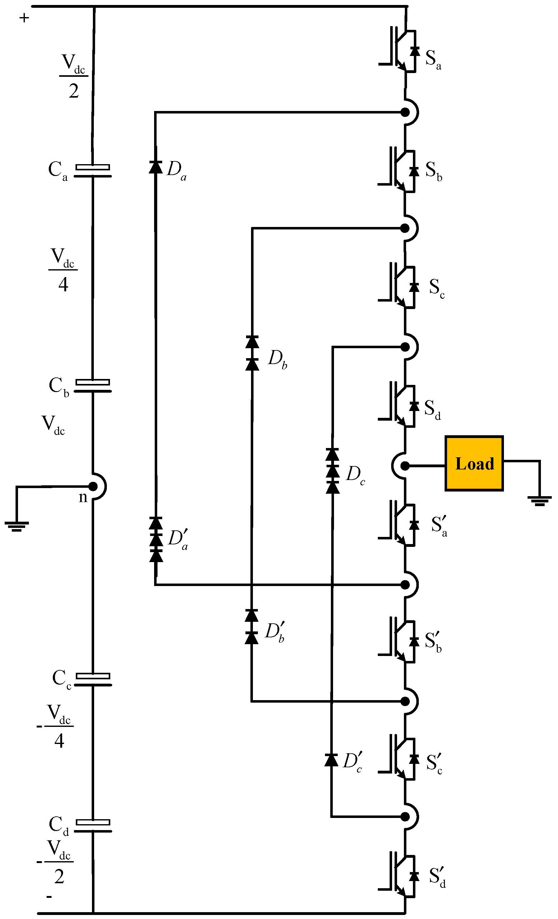
2.1. Multilevel Diode Neutral-Point Clamped Inverter

Multilevel inverter (MLI) was proposed in 1975, its design was like a cascade inverter with diodes facing the source. This inverter was later transformed into a Diode Clamped Multilevel Inverter, which is also named as a Neutral-Point Clamped Inverter (NPC) [39]. In this type of multilevel inverters, the integration of voltage clamping diodes is indispensable. An ordinary DC-bus is separated by an even number of bulk capacitors connected in series with a neutral point in the middle of the line that is dependent on the voltage levels of the inverter. In Figure 2, a five-level NPC-MLI is shown, here the clamping diodes are interlinked to M-1 regulatory pairs if M is considered as voltage levels of the inverter.
The neutral point converter was designed by Nabae, Takahashi and Akagi in 1981, this was basically a three-level diode-clamped inverter [40]. A three-phase Three-level diode-clamped inverter is shown in Figure 3.
The NPC-MLI is considered as an important device in conventional high-power ac motor drive applications like mills, fans, pumps and conveyors, moreover, it also offers solutions for industries including chemicals, gas, power, metals, oil, marine, water and mining. The back-to-back configuration of inverters for reformative applications is also considered as a major plus point of this topology, used, for example, in regenerative conveyors, mining industry and grid interfacing of renewable energy sources like wind power [41].
There are several benefits as well as drawbacks of multilevel diode-clamped [39,42]. A common dc bus is shared by all the phases, this results in the reduction of capacitance requirements of the inverter. Due to this reason, implementation of a back-to-back topology is not only credible but can also be applied practically for performing different operations in an adjustable speed drive and a high-voltage back-to-back inter-connection. The capacitors can be recharged as a group. On fundamental frequency, switching efficacy is relatively higher. However, real power flow is problematic in case of a single inverter as the intermediate dc levels will tend to overcharge or discharge due to inappropriate monitoring and control. The number of clamping diodes are quadratically associated with the number of levels, which can be unwieldy for units with a high number of levels.

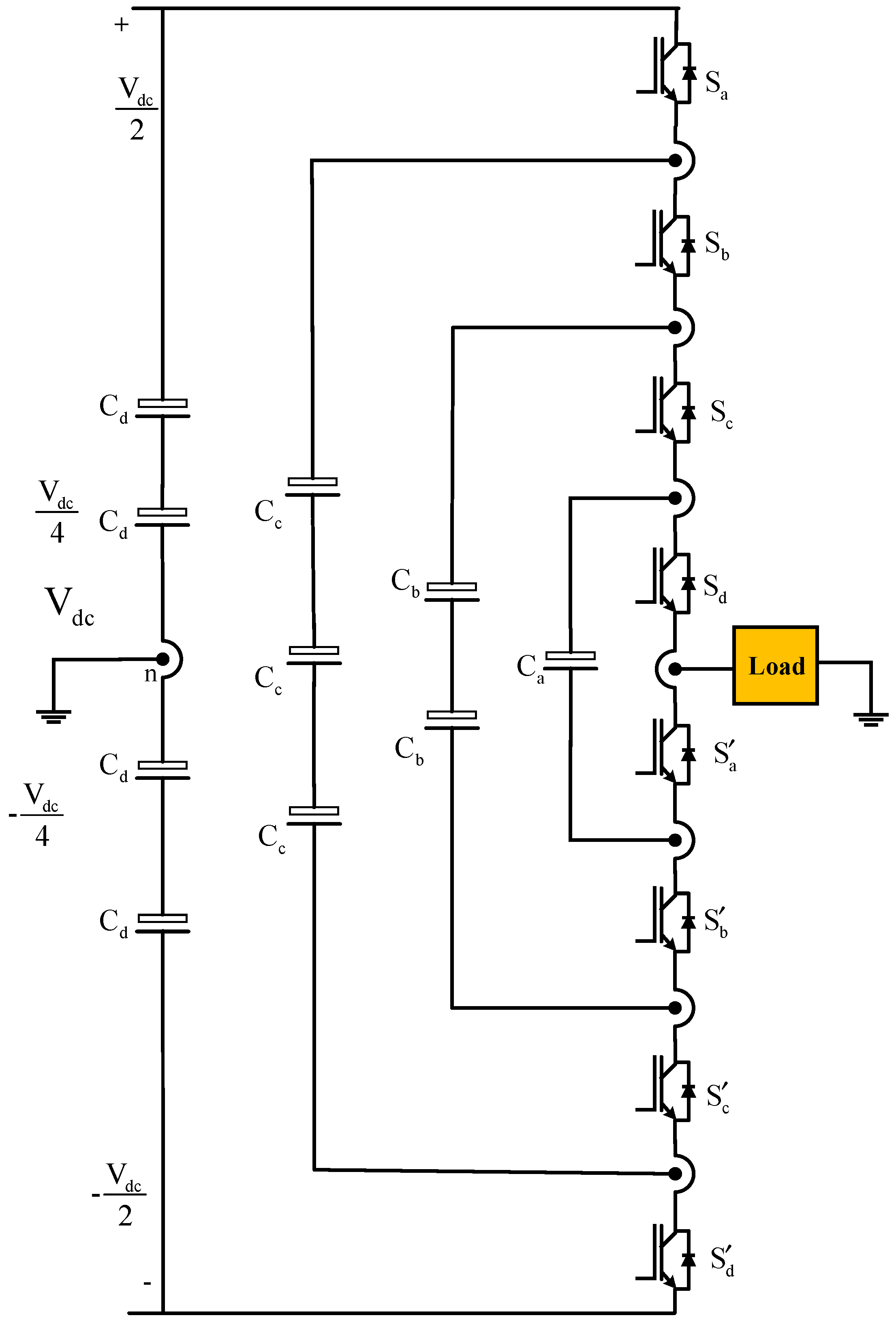
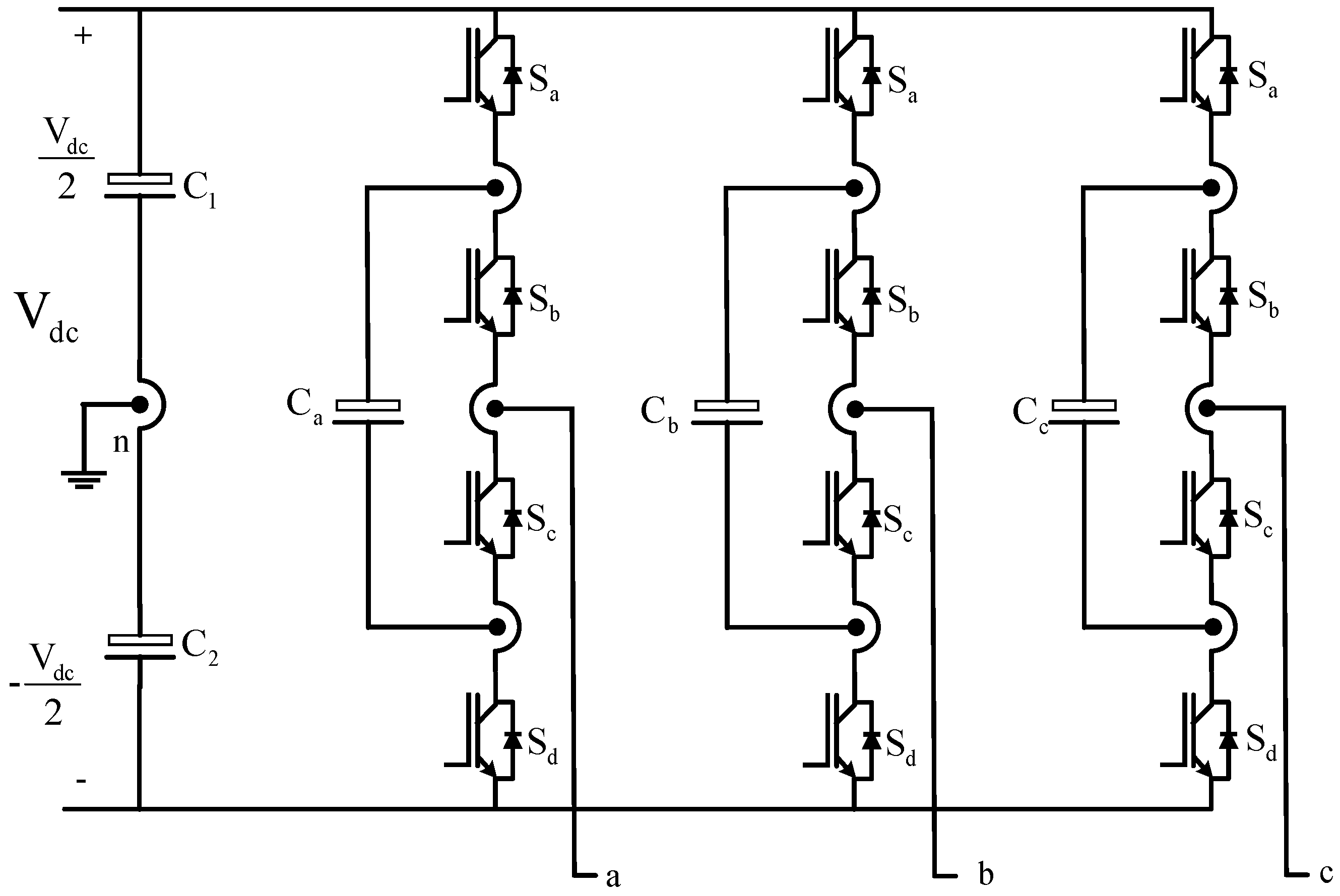
2.2. Multilevel Capacitor Clamped/Flying Capacitor Inverter

A corresponding topology for the NPC-MLI topology is the Flying Capacitor (FC), or Capacitor Clamped, MLI topology, it is depicted in Figure 4. As an alternative to clamping diodes, capacitors are used for holding the voltages to the referred values. In the NPC-MLI, M − 1 number of capacitors are integrated on a shared DC-bus, where M is the level number of the inverter and 2(M − 1) switch-diode regulatory pairs are used. Though, for the FC-MLI, instead of clamping diodes, one or more capacitors are used to produce the output voltages depends upon the position and the level of the inverter. They are coupled to the midpoints of two regulatory pairs on the same position on each side of a midpoint [42], see capacitors Ca, Cb and Cc in Figure 5.
The basic difference is the usage of clamping capacitors in place of clamping diodes, as using them increases the number of switching combinations as capacitors do not block reverse voltages [42]. Numerous switching states would be able to produce the same voltage level and the redundant switching states would also be available.
DC side capacitors in this topology have a ladder-like structure and the voltage on each capacitor deviates from that of the other capacitor. The voltage increment between two adjacent legs of the capacitors provides the size of the voltage steps in the output waveform. One advantage of the flying-capacitor-based inverter is the redundancies for inner voltage levels; i.e., two or more effective switching amalgamations can produce an output voltage.
Unlike the diode-clamped inverter, the flying-capacitor inverter never requires all of the switches to be on (conducting state) in a consecutive series. Moreover, the flying-capacitor inverter has phase redundancies, while the diode-clamped inverters have only the line-line redundancies [40]. These redundancies provide selective charging and discharging of specific capacitors and it can be incorporated in the control system for the voltage balancing across the various levels.
There are several advantages and disadvantages of multilevel flying capacitor inverters [41,43]. Phase redundancies are offered for balancing the voltage levels between the capacitors. Active and reactive power flow can be regulated. The presence of various capacitors allows the inverter to ride through outages for short duration and deep voltage sags. However, the control system is complex for tracking the voltage levels for all of the capacitors. Correspondingly, recharging all the capacitors to the same voltage level and startup are complex. Switching operation and efficacy are poor for real power transmission. The installation of large numbers of capacitors is not much economical and it also makes the system bulky as compared to the clamping diodes in multilevel diode-clamped converters. Likewise, packing is also tougher in the inverters with a higher number of levels. The five-level and three-level FC-MLIs are represented in Figure 4 and Figure 5 respectively.

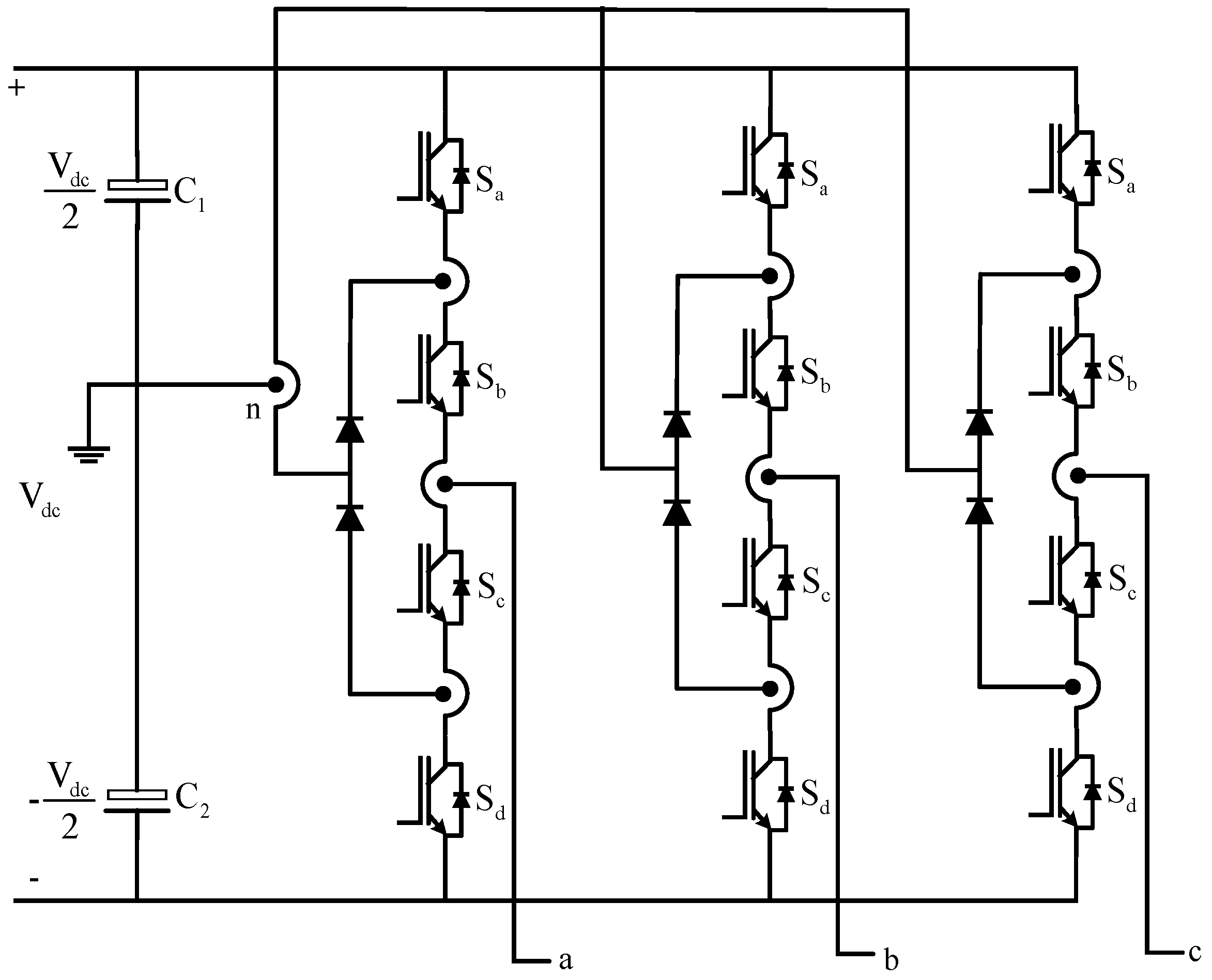
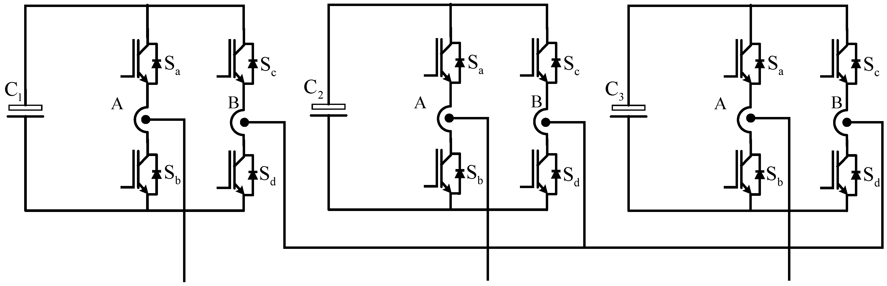
2.3. Cascaded H-Bridge Inverter

There are minimum three voltage levels for a multilevel inverter using cascaded topologies. In order to attain a three-level waveform, a single full-bridge or H-bridge inverter is considered. Each inverter is provided with a separate DC source. A three-level cascaded inverter is shown in Figure 6.
By using different combinations of the four switches, Sa, Sb, Sc and Sd, each inverter level can produce three different outputs of voltage, i.e., V dc , 0 and V dc by connecting the dc source to the ac output. V dc can be obtained by turning on switches Sb and Sc whereas for obtaining V dc , switches Sa and Sd can be turned on. However, for achieving the output voltage on 0 level either Sa and Sb or Sc and Sd can be turned on. The different full-bridge inverters must be connected in series in the way that the finally produced voltage waveform should be the sum of the inverter outputs. Multilevel cascaded inverters are proposed for the applications such as static VAR generation (reactive power control), an interface with renewable energy sources and for battery-based applications. The main reasons for preferring a cascaded multilevel H-bridge inverter are the availability of possible output levels more than twice the number of dc sources [42,43,44]. The series of H-bridges enables the manufacturing and packaging process more easy, quick and economical. However, the requirement of a separate dc source for each H-bridge constrains the applications of these inverters to the products having multiple separate DC sources already or readily available.

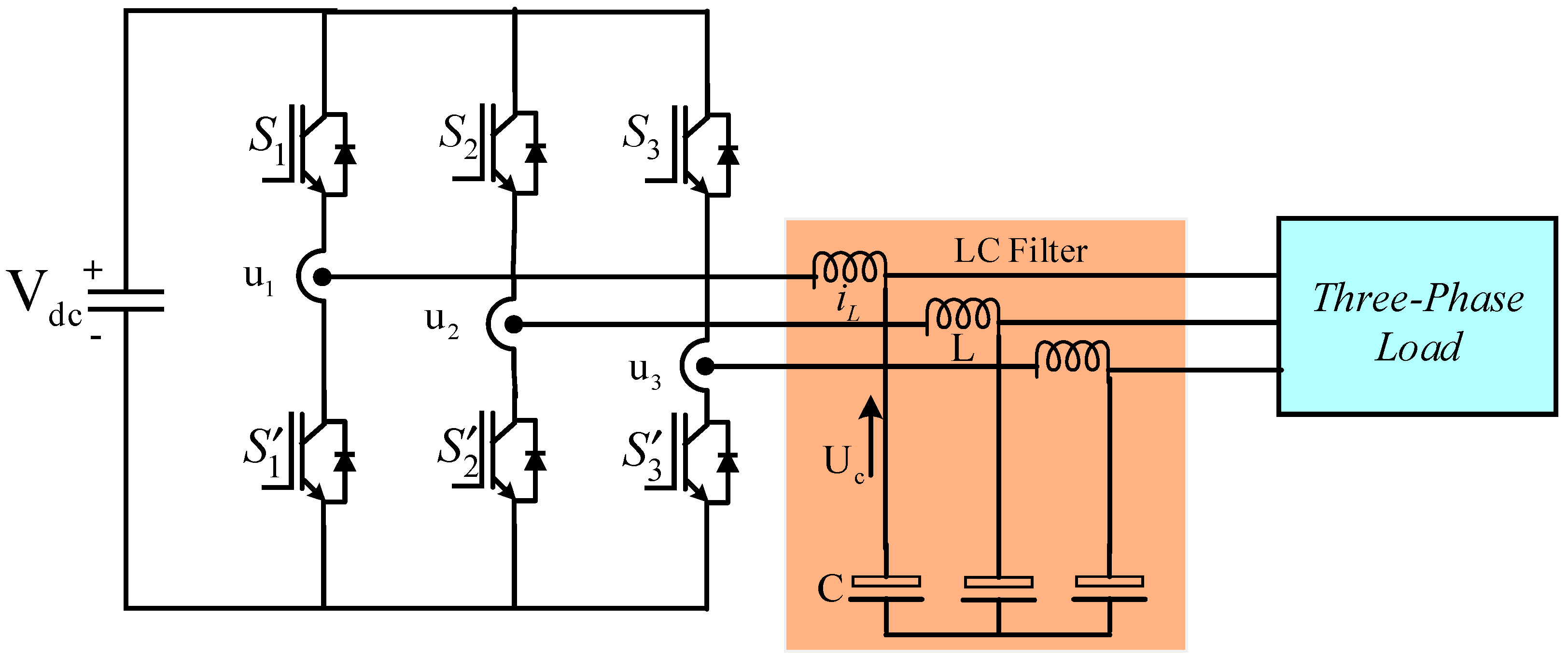
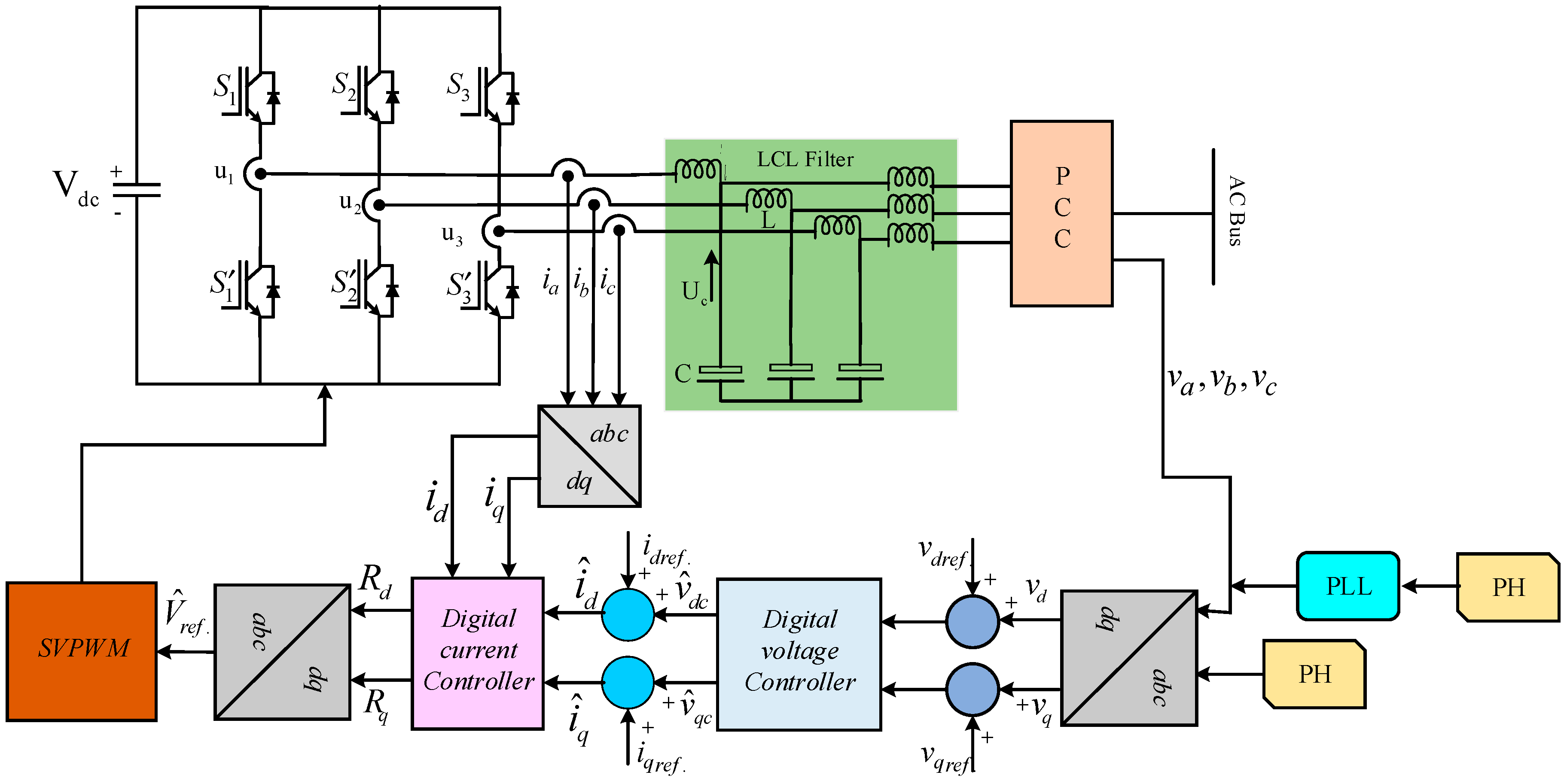
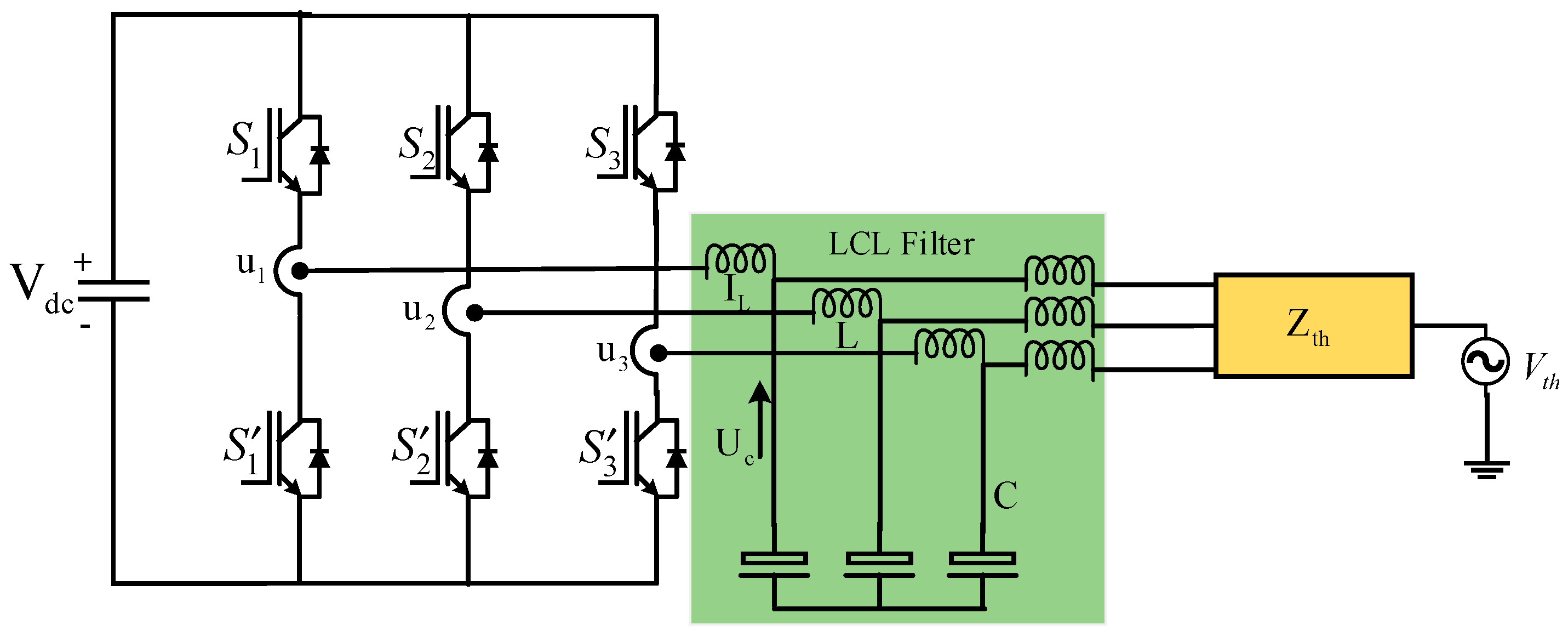
2.4. Two-Level Three Phase VSI with an Output Filter

A simple two-level inverter is used to convert dc to ac output. It consists of six switches, IGBTs and MOSFETs are the two most suitable switching components for these inverters. Due to simplicity in their structure and ability to handle the voltage by keeping the system stable, they are preferred utmost in the industry and for commercial purpose due to their support in uninterruptible power supply applications. These are usually connected to the load or the grid by using LC or LCL filter. Various types of control systems are implemented by the researchers to improve their performance, robustness and stabilization, compensating the power losses and lowering the THD value. SPWM or SVPWM are mostly applied to these types of inverters for getting appropriate values. Two level three phase VSI is shown in Figure 7. In Figure 7, the S1 to S3 and S 1 to S 3 shows the switches of the inverter. Whereas, u c represents the voltage across the capacitors, C.

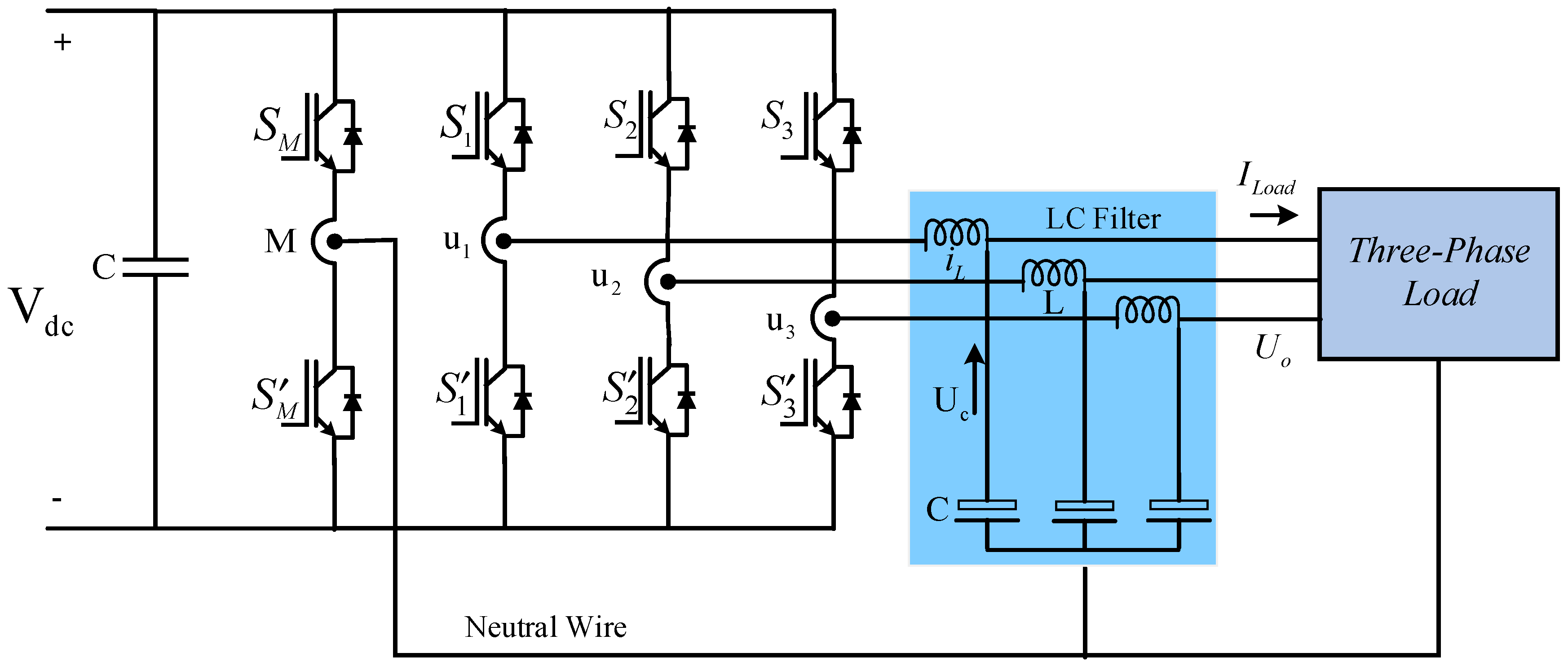
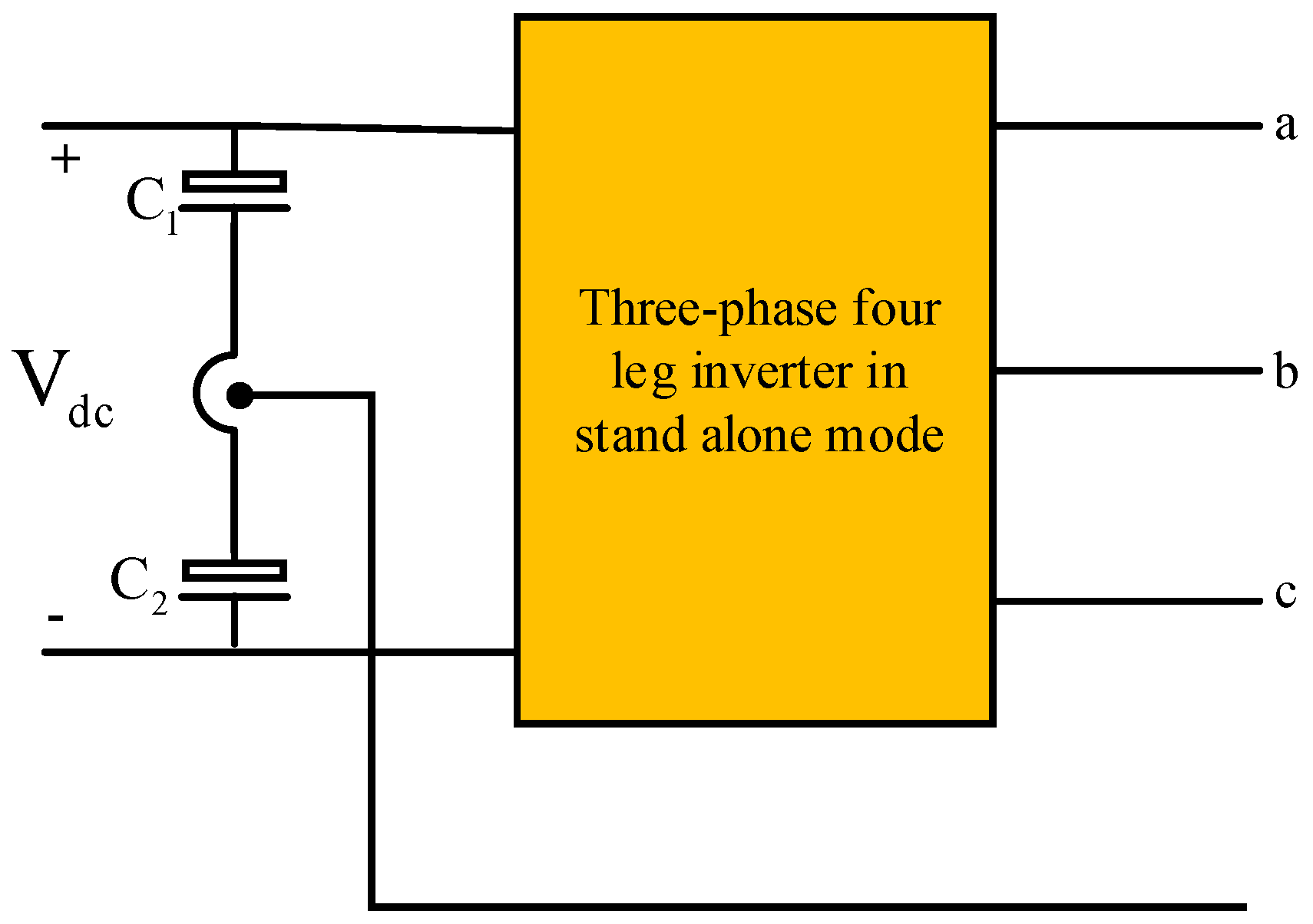
2.5. Three Phase Four-Leg VSI with an Output Filter

Nowadays, a growing interest in using the three-phase four-leg inverters is observed from the researchers’ due to their ability to handle the unbalanced loads efficaciously in four-wire systems [45,46]. In this topology, the neutral point is proposed by connecting the neutral path to the mid-point of the additional fourth leg, as shown in Figure 8. In Figure 8, u o represents the output voltage of the LC filter, whereas M represents the point neutral point between two switches, S M and S M . Even though the configuration in this topology does not need expensive and large capacitors and produces lower ripple on the DC link voltage, however, using two extra switches lead to a complex control system [47]. Additionally, the split DC-link voltage is about 15% less as compared to the AC voltage in this configuration [48].
Another topology can be using split DC link, which is the most common way of providing a neutral point to three-phase VSIs. This configuration can be provided by using two capacitors i.e., splitting the DC-bus into two parts by using a pair of capacitors and by connecting a neutral path to the mid-point of these capacitors, as shown in Figure 9. Both these configurations have several advantages and disadvantages, however, the split dc-link is found unsuitable for handling the unbalanced loads, whereas, three-phase four leg inverter is found most appropriate for handling the non-linear and unbalanced load conditions. A comparison of different types of VSIs with respect to their characteristics, control contents and complexity is described in Table 1.

3. Characteristics of Control Systems

There are several parameters and characteristics through which a particular control system is identified. Mainly, there are two characteristics of a control system are found i.e., analog or digital control systems. Both are having some advantages and disadvantages, described as follows:

3.1. Analog Control System

The control systems in which the input and output are designed and analyzed by continuous time analysis or Laplace transform (in s-domain) using state-space formulations. In analog control systems, the representation of the time domain variable is assumed to have infinite precision. Hence, the equations of state space model are differential equations. These systems can be designed without using a computer, microcontrollers or a programmable logic control (PLC). Implementation of analog signals is generally done by using Op-amps, capacitors etc. Robustness against crash or breakdown, having a wide dynamic range, analytical composition accessibility and continuous processing indicate numerous advantages of the analog control systems. However, slow processing speed, interference, complicated implementation in comparative logic, intelligent control systems, neural networks and MIMO are several disadvantages of analog control systems.

3.2. Digital Control System

In digital control systems, modeling, designing, implementation and analysis is carried out in discrete-time or z-transformation domain. In digital control systems, as the name depicts that digital signals are analyzed. Therefore, time is sampled and quantized for state space equations. Additionally, as a digital computer has finite precision, extra attention is needed to ensure that error in coefficients, i.e., A/D conversion, D/A conversion etc. are not producing any disturbances or inadequate effects. In a digital controller, the output is a weighted sum of current as well as previous input and output samples, therefore, its implementation requires the storage of relevant values in a digital controller.
Mostly, a digital controller is implemented via a computer, so, found most economical to control the plants. Moreover, it is relatively easier to constitute and reconstitute through software. Likewise, programs can be leveled to the confines of storage without any additional cost. Correspondingly, digital controllers are compliant with constraints of the program can be changed. Furthermore, the digital controllers are less responsive to the changes in environmental conditions, unlike the analog controllers. Flexibility, swift expansion, uncomplicated implementation in comparative logic, intelligent systems and MIMO, high accuracy as well as robustness against interference are several advantages of these systems. Though, low processing speed, low dynamic range and non-user-friendly interface are the several drawbacks of the digital control systems. The digital controllers are implemented with various technologies which are classified into three categories expressed as follows:
  • Microcontroller Based implementation (MC) [49,50,51]
  • Digital Signal processing-based implementation (DSP) [52,53,54]
  • Field programmable gate array-based implementation (FPGA) [55,56,57]
In reliable scientific research, generally, DSP is used. Fixed point arithmetic and floating-point algorithms are mostly used in implementing the digital control technique by DSP. A traditional slow microprocessor is used normally in slow applications. However, an FPGA is found adequate in fast controllers, due to its abilities of bug fixing and to be reprogrammed in complex structures.
A general structure of a closed loop grid connected digital control system, with an inner current loop and an outer voltage loop, is depicted in Figure 10. In this figure, a voltage source inverter with an output filter is considered. An AC bus is connected to point of common coupling, PCC. Moreover, coordinates transformation from abc to dq is achieved by a phase angle, PH. However, PLL represents the phase locked loop. The symbols S 1 , S 2 , S 3 , S 1 , S 2 and S 3 represents the switches, responsible for positive and negative sequences of the inverter output.
The v d r e f . and v q r e f . represents the reference voltages in dq frame. SVPWM shows the space vector pulse width modulation technique for generating drive signals for a voltage source inverter.
The voltage across capacitors, u c and current across inductors, i L are measured and transformed into a synchronized dq reference frame. The input voltage is computed in the dq frame on the basis of v r e f . in the three-phase reference frame. The computed data is then transformed from rotating dq to abc reference frame. Afterward, the PWM technique would be selected accordingly.

4. Reference Frames

Control systems are implemented in either a single phase or a three-phase synchronous reference frame. These frames are synchronized with each other through special formulation in order to be compatible for facilitating the modeling, design, analysis and transformation of one phase and three phase systems into other systems. Complex structures, especially for multi-level converters, can be simplified by using these reference frames describes as follows [1,58].

4.1. abc Reference Frame

A general three-phase system is said to be applied to abc frame without any transformation. An individual controller is to be used for each phase current in abc frame but Delta and star connection has to be considered for designing a control system. Non-linear controllers are used in this system due to their rapid dynamic response.

4.2. dq Reference Frame

This frame is used in three-phase systems. Park’s Transformation is used for transforming the abc frame into dq frame. This transformation causes the current and voltage waveforms to be converted into a frame that rotates synchronously with the grid voltage. As a result, the variables are converted into DC variables and they can easily be controlled and filtered if required.

4.3. αβ Reference Frame

This frame is used in three-phase systems and sometimes sensationally in single phase systems too. Grid current is transformed into a stationary reference frame from abc frame or single-phase frame by using Clark’s transformation. Therefore, by using this transformation control variable can be transformed into sinusoidal quantities.

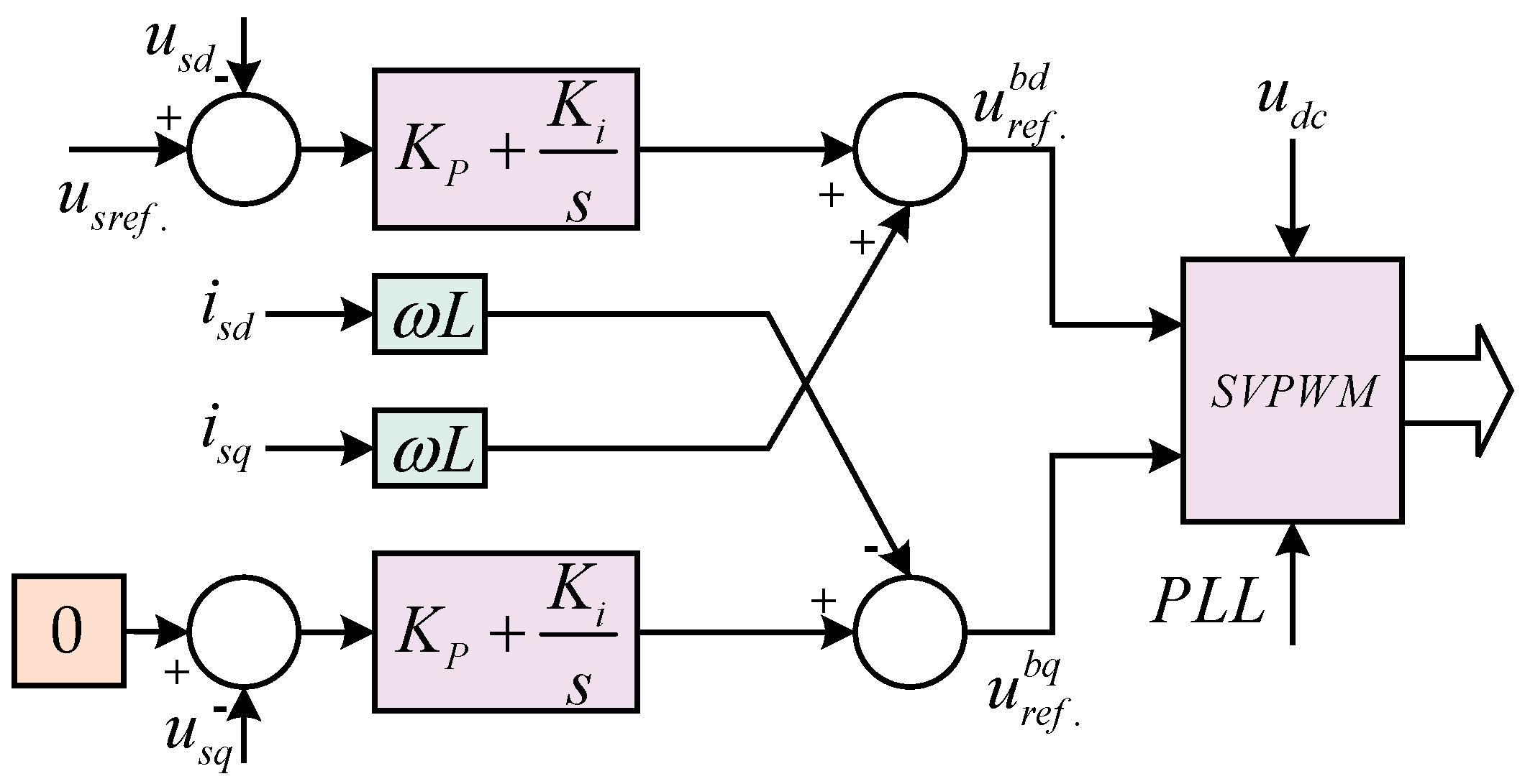
5. The Control Strategy in Decoupled dq Frame

In a digital control scheme in dq reference frame, decoupling is the most important issue to be discussed. Generally, a balanced and interrupted sinusoidal waveform can be obtained by adopting ac voltage control in an inverter station. Therefore, the fundamental requirement is to simplify the control design [59]. The controller in an inverter station is based on a mathematical steady-state model in the synchronous reference frame. Moreover, during a balanced network state, the direction of the current injected into the loads is assumed as the reference direction. The mathematical representation of a steady-state model is expressed as following:
{ u b d = ω L i s q + u s d u b q = ω L i s d + u s q
In Equation (1), the terms u b d and u b q represents the voltages in dq frame under balanced network conditions. Likewise, k p and k i represents the proportional and integrated controllers and the equation by using aforementioned coefficients represents a PI controller. Correspondingly, u s d and u s q represents the bus voltages in dq axis. However, i s d and i s q represents the active and reactive current respectively. Commonly, the d-axis is fixed to the voltage source space vector, i.e., the amplitude of the desired ac voltage space vector is kept constant and the value of u s q = 0 . Then Equation (1) can be simplified as:
{ u b d = ω L i s q + u s d u b q = ω L i s d
According to Equation (2), the control structure of the inverter station is shown in Figure 11, where a PI controller is employed in the ac voltage control [60]. Moreover, u s r e f . is the reference voltage which can be set accordingly for the desirable amplitude of AC bus voltage.

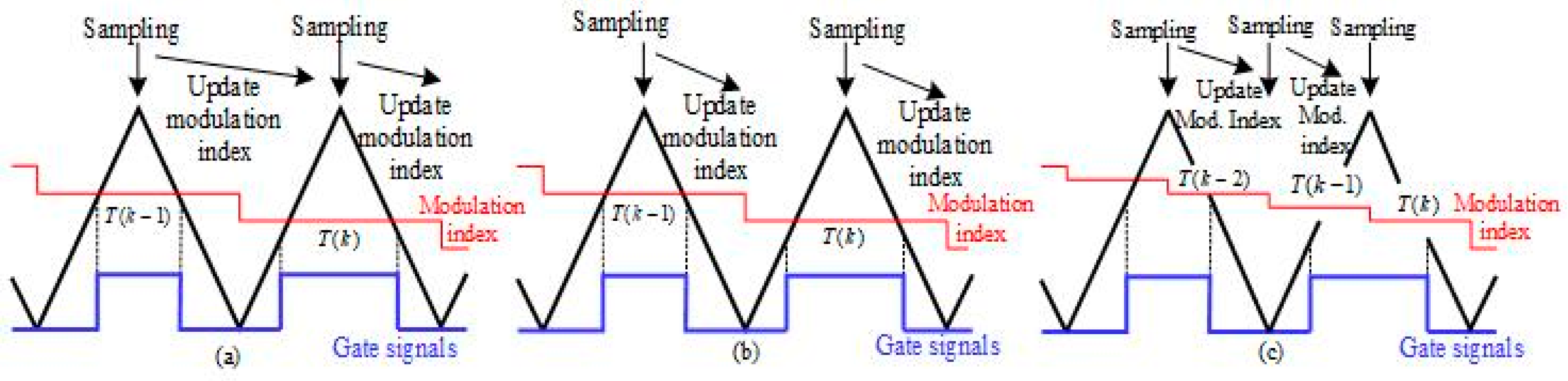
6. Time Delay Sampling Scheme for VSI

Time sampling for digital controllers is done by using a discrete time-domain analysis, i.e., z-domain. Two fundamental advantages of using z-domain analysis over s-domain (continuous time domain) analysis for designing a current controller are: First the control implementation is achieved on a computer-based system, i.e., the control calculation, sampling measurements and PWM signals sequence are updated in discrete time steps. Although, this sample and hold feature is a characteristic of a control system and effects its dynamics as per the referred sampling frequency. Secondly, the multiple time delays can be modeled by using a backshift operator, which affords no simplifications in linear control design, unlike continuous time domain, where the multiple time delays were sampled using an exponential term, which is approximated generally by applying Taylor-series expansion. The sampling effect is a most critical requirement to handle model uncertainties, issues in power supplies and relative disturbances. Therefore, in order to deal with aforementioned issues, zero order hold, ZOH should be incorporated in the control system. In ZOH, a pole or a zero is added into the existed controller through the compensator. The fundamental advantage of this technique is its uncomplicated structure to be implemented on a system, though, it only affects a limited share of the overall delay.
There are two basic sampling routines generally employed in the digital control systems, i.e., single updated sampling and double updated sampling [61]. A single-update sampling method comprises of the measurement samplings, in which calculated modulation indexes are updated once in every switching period. Whereas, a double-update sampling concept conferred to a PWM concept in which the measurement sampling and therefore, the calculated modulation index are updated twice in every switching period [61]. The detailed single-update and double-update sampling are shown in Figure 12, where, T(k) represents the switching period of the present time slot. However, T(k − 1) and T(k − 2) shows the switching period of the former time slots.
A single-update PWM-technique with sampling at the beginning of a switching period is depicted in Figure 12a. In this technique, the modulation index is updated once in beginning of a switching period. A time domain of one sampling time is introduced in the control loops. This effect is modeled with a backshift operator while taking discrete time domain into the account.
Figure 12b shows another scheme of a single-update PWM sampling in which the modulation index is updated in middle of a switching period. Therefore, the time delay due to sampling and updating routine is the mean value of the two converter voltage reference values, i.e., actual and former control cycles. Therefore, the transfer function of a single-update PWM technique with sampling in middle of a switching period is determined.
In the double-update sampling concept, sampling and updating occurs twice in each sampling period. In this technique, the modulation index is updated on the basis of former control cycle’s measurements. According to this behavior, the time-delay is one control cycle. The pattern of a double-update sampling is presented in Figure 12c.

7. Output Filters for Inverters

The harmonics reduction is the foremost priority of the researchers while designing a power electronics or an electrical system. Therefore, an output filter is used for this purpose. An output filter uses the controlled phenomenon of switching the semiconductor devices for harmonics reduction. There are numerous topologies of such filters introduced in the literature by combining the inductor (L) and capacitor (C) i.e., L, LC and LCL filters unified with the inverters to their output.

7.1. L-Filter

In high switching frequency inverters, the first order L-filter is considered as the most suitable filter. However, inductance decreases the dynamics of the whole system.

7.2. LC-Filter

An LC filter is a second-order filter having substantially sophisticated damping behavior as compared to an L-filter. This filter topology is relatively easier to design and it is a compromise between the values of inductance and capacitance. The cut-off frequency needs the relatively higher value of inductance whereas the voltage quality can be improved through the higher value of capacitance. The value of resonant frequency is dependent on the impedance of the grid when the system is connected to the grid supply. An LC-filter is mostly preferred in standalone mode. The three-phase two-level and three-phase four legs voltage source inverters with an integrated LC filter are shown in Figure 7 and Figure 8 respectively.

7.3. LCL-Filter

An LCL filter is a third order filter, mostly used for the grid-tied inverters. The lower frequency is preferable in presence of aforementioned filters. This filter supports the comparatively healthier decoupling between the filter and the grid impedance. This filter should be precisely designed by taking into consideration the parameters of the inverters. Otherwise even the smaller values of inductance can bring resonance and unstable states into the system. However, the smaller inductance can provide optimized current ripple diminishing values. A three-phase VSI with an LCL filter is shown in Figure 13. Where, V t h and Z th represents the Thevenin voltage and Thevenin impedance respectively. However, the complexity of the control system inflated significantly and the dynamic performance of the inverter can perhaps be affected when relatively complex filter structures are employed. Thus, these topologies are most suitable for high power applications, which employ low switching frequencies. However, Figure 14 and Figure 15 show the one-leg block diagram of a single-phase and three-phase grid-connected systems, respectively. Where, K pwm represents the pulse width modulation characteristic of the system, whereas, u g , u i , u c , L g , L i , i i and i g represents the grid side voltage, inverter side voltage, voltage across capacitor, grid side inductance, inverter side inductance, inverter side current and grid side current respectively.

8. Damping Techniques for Grid-Connected VSIs

In the grid-connected applications, LCL filter is highly preferred due to its harmonic suppressing capability. In this case, the voltage across the point of common coupling PCC is controlled in synchronism with the current. Therefore, it becomes possible to regulate the active and reactive power injected into the grid according to the requirement. The LCL filter offers a resonance frequency which can be a source of instability in the closed-loop system. This problem is stated by various researchers in the literature and numerous damping strategies are proposed to solve it [62,63,64,65]. Damping methods can be classified into two groups. (i) Passive damping and (ii) Active damping.

8.1. Passive Damping

Passive damping is to inserting passive elements in the filter for reduction of the resonant peak in the system [32]. Generally, passive damping schemes never desire any amendments in the control strategy. Though, these approaches change attenuation of the filter, as a result of which losses increases [18,32,34]. The passive damping techniques, presented generally in the literature, results in the addition of a simple resistor in series with the filter capacitor [63]. The major drawback of this technique is a reduction in filter attenuation, increasing power losses and large filter volume [62]. A general schematic of passive damping control strategy for a grid connected VSI is shown in Figure 16.

8.2. Active Damping

The active damping methods are proposed to overcome the drawbacks associated with the passive damping techniques. Active damping techniques offer modifications in the control policy in order to afford closed loop damping [65,66]. The active damping techniques are classified into 3 groups, i.e., single loop, multi-loop and complex controllers. Single loop methods are incorporated to damp the LCL filter resonance, without supplementary measurement. These methods comprise of low pass filter-based method, virtual flux estimation method, sensor-less method, splitting capacitor method, notch-filter method and grid current feedback method. Generally, single-loop methods are found relatively robust during uncertainty in parameters and variation in grid inductance [62]. Multiloop methods explore additional measurements. This group comprises of capacitor current feedback, capacitor voltage feedback and weighted average current control techniques. However, the third group of active damping methods is based on complex control structures. This outcome of these techniques is usually a suitable and a robust dynamic response [67]. These techniques include predictive control, state-space controllers, adaptive controllers, sliding mode controller and vector control. Additionally, when LCL filter is selected, there are two options for current control: grid current or converter current. Various techniques are proposed but there exists a disagreement in the literature about the suitable solution of these issues and it is agreed that the current control strategy should be carefully selected. An active damping technique with a damping resistance as well as a harmonic compensator are described in [65]. A general schematic of active damping control strategy for a grid connected VSI is shown in Figure 17.

9. Grid Synchronization Techniques

The grid voltage must be synchronized with the injected current in a utility network for a significant output. In synchronization algorithm, phase of the grid voltage vector is considered and control variables i.e., grid voltages and grid currents are synchronized by using it. Various methods are introduced in literature for extracting the phase angle [68]. Some commonly used techniques found in credible research articles are discussed as:

9.1. Zero-Crossing Technique

The simplest method to implement is Zero-Crossing method. However, it is not considered on a larger scale due to poor performances reported in the literature. Especially, during voltage variations, ample values of harmonics and notches are observed.

9.2. Filtering of Grid Voltages

The grid voltages can be filtered in the dq frame as well as in the αβ reference frame. The performance of zero-crossing method is improved by voltage filtering [68]. However, it is a complicated process to extract the phase angle out of utility voltage, especially during a fault condition. This method uses the arctangent function to realize the phase angle. Generally, a delay is observed in processing a signal while using the filtering method. Therefore, designing of the filter must be considered critically.

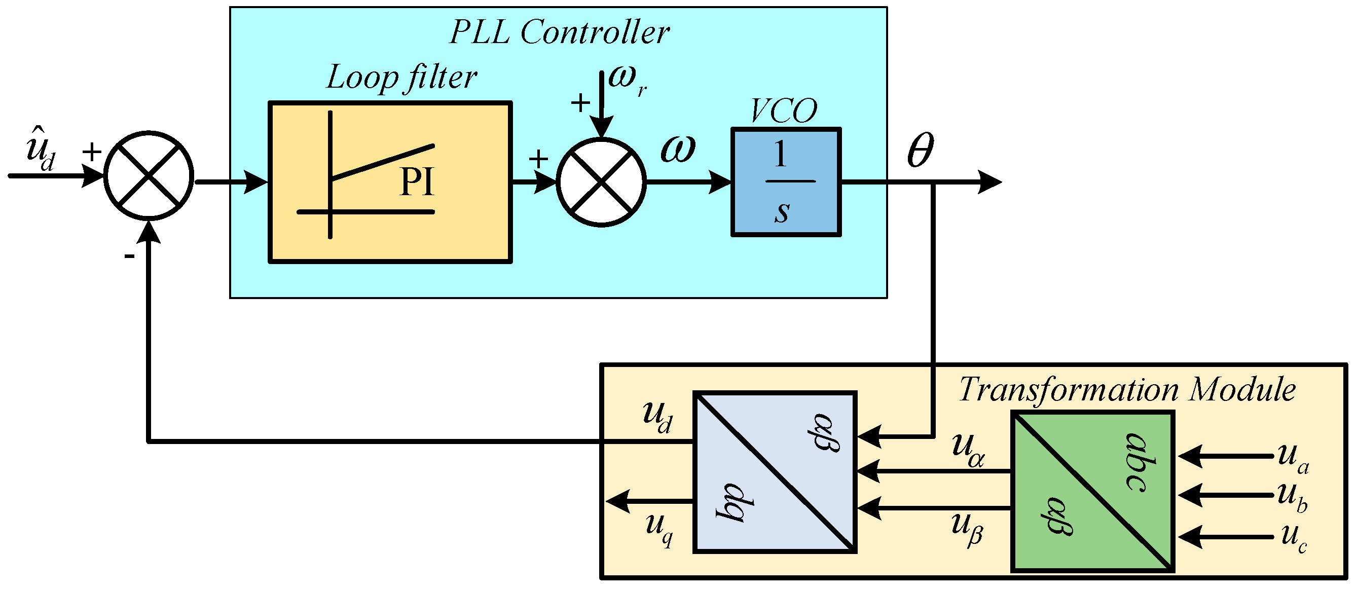
9.3. Phase Locked Loop Technique

The phase locked loop, PLL technique is considered as the state-of-the-art method to obtain the phase angle of the grid voltages. The PLL is implemented in dq-synchronous reference frame. In this case, the coordinates transformation from abc to dq is preferred and reference voltage, u ^ d would be set to zero for realizing the lock. A general schematic of PLL technique is depicted in Figure 18. A PI regulator is generally used to control the reference variable. Afterward, the grid frequency is integrated in the system and utility voltage angle is acquired after passing through a voltage-controlled oscillator, VCO. This voltage angle is then fed into the αβ to dq transformation module for transforming into the synchronous reference frame.
This technique is found the most suitable for rejecting notches, grid harmonics and other disturbances. However, additional improvements are needed to handle the unsymmetrical voltage faults. Especially, filtering techniques to filter the negative sequence should be proposed in case of unsymmetrical voltage faults, as second-order harmonics are propagated by the PLL system and reflected in the obtained phase angle. Moreover, it should be assured to estimate the phase angle of the positive sequence of the grid voltages during unbalanced grid voltages [68].

10. Modulation Schemes

In power electronics converters, the major problem is the reduction in harmonics. PWM control techniques provide the most suitable solution for harmonics reduction. A sinusoidal output having controlled values of frequency and magnitude is the core purpose for using these PWM techniques. Primarily, PWM techniques are classified into three major categories i.e., Triangular Comparison-based PWM (TC-PWM), Space Vector-based PWM (SV-PWM) and Voltage look-up table-based PWM (VLUT-PWM).

10.1. Triangular Comparison Based PWM

In Triangular Comparison based PWM (TC-PWM) techniques, PWM waves are produced by the combination of an ordinary triangular carrier and a fundamental modulating reference signal. The triangular carrier signal has relatively very higher frequency than that of a fundamental modulating reference signal. The magnitude and frequency of the fundamental modulating reference signal control the magnitude and frequency of the central module in the grid side. PWM and Synchronous PWM (SPWM) are the core techniques to be mentioned in TC-PWM [69].

10.2. Space Vector Based PWM

In SVPWM techniques, the revolving reference vectors provide the reference signals. The magnitude and frequency of central module in grid side are controlled by the frequency and magnitude of the revolving reference vectors respectively. This technique was first introduced to generate vector based PWM in the three-phase inverters. However, nowadays it is expanded to various other newly introduced inverters. SV-PWM is considered to be the more advanced technique for PWM generation for getting qualified sinusoidal output with low THD values [69].

10.3. Voltage Look-Up Table-Based PWM

In VLUT-PWM, a new method is introduced to obtain the voltage reference based on the current reference for an inverter. The major advantage of this technique is its compatibility and simplicity with the load conditions. The switching frequency in this technique is usually taken significantly lower as compared to various other presented techniques [52].

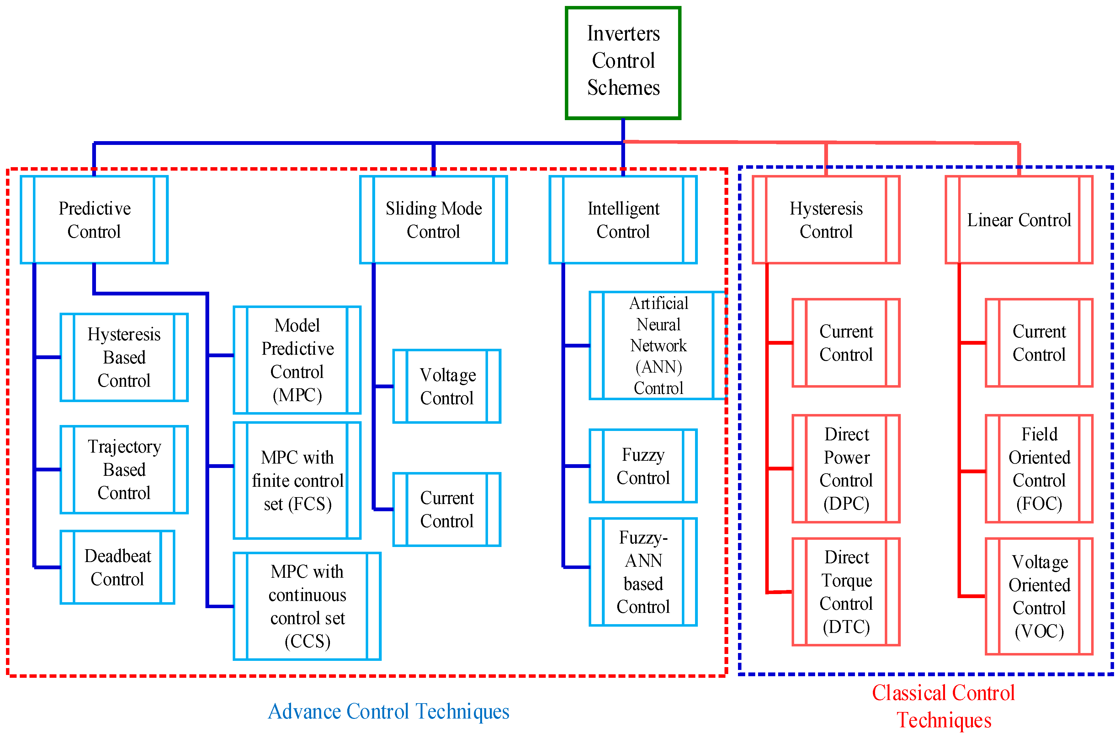
11. Control Techniques

Connecting the grid to the distributed generation system plays a key role and if bit negligence is shown in implementing this procedure, a number of problems can arise i.e., the grid uncertainty and disturbance, so in order to overcome this situation, a suitable controller must be designed for it. In this section, the most appropriate control techniques are described according to their applications. Various single loop and multiloop control systems are discussed in the literature for power droop control, voltage and current control. In which inner loop is for current regulation and outer loop is for voltage regulation [13,70,71]. In Figure 19, the categorization of classical an advanced control technique is depicted clearly.

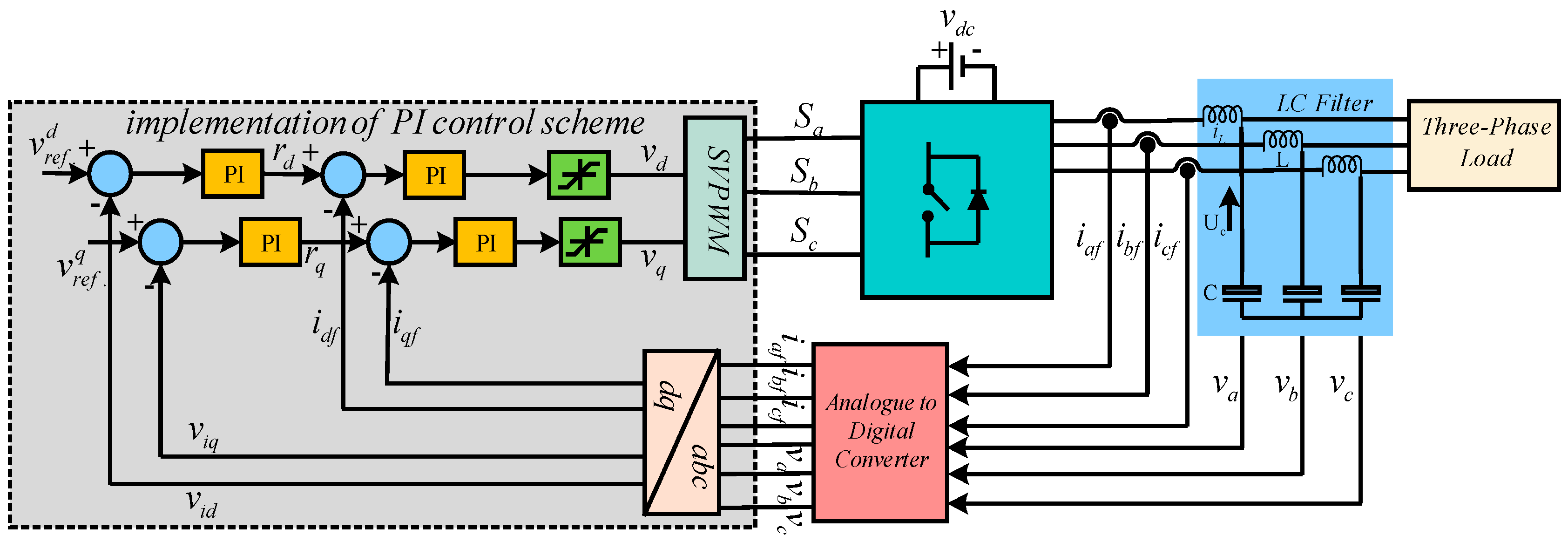
11.1. Classical Control Techniques

The classical controllers include the category of controllers for adding or subtracting a proportion and adjusting the system accordingly. These controllers involve proportional (P), proportional integration (PI), proportional integral derivative (PID) and proportional derivative (PD) controllers. These controllers are considered as the most fundamental controllers in the industry for controlling linear systems and considered as the base of control theory. Lot of work in literature is being done on these controllers [49,50,51,52,72,73,74,75,76,77,78]. The fundamental benefits of implementing these controllers are their ability to tune themselves according to the requirement of the plant and their simple structure. Moreover, they are the most commonly used controllers on commercial levels, so easily available. However, their tracking ability, response time and ability to handle stable error are relatively lower as compared to modern state-of-the-art controller. The schematic of a digital PI controller for controlling a three-phase VSI with an LC filter in stand-alone mode is shown in Figure 20. In Figure 20, i a f , i b f and i c f represents the filter current across phase a, b and c respectively. Likewise, v a , v b and v c characterizes the voltage across phase a, b and c respectively. Likewise, i d and i q represents the current across the d and q axis respectively. Moreover, S a , S b and S c represents the switching commands across phase a, b and c respectively. Correspondingly, V r e f . d and V r e f . q symbolizes the reference voltages along d and q axis respectively.

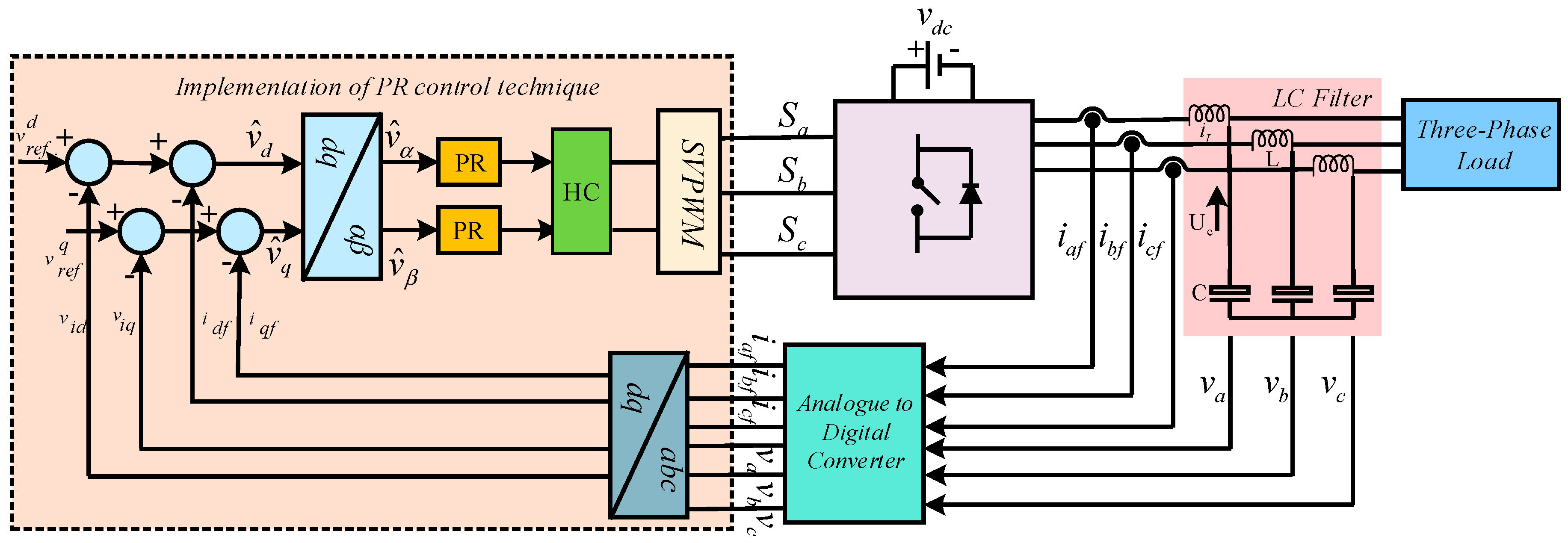
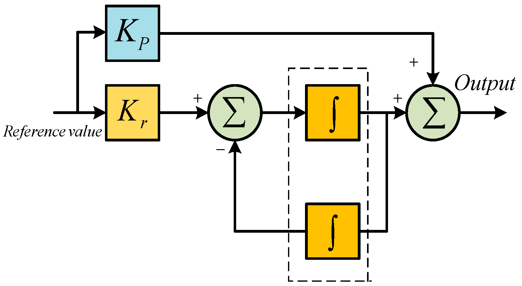
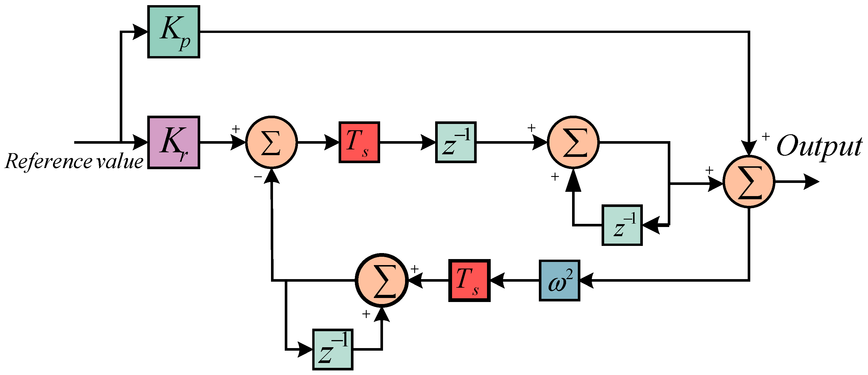
11.2. PR Controllers

PR controllers are the combination of proportional and resonant controllers. The frequencies closer to resonant frequency are integrated by the integrator. Therefore, phase shift or stationary error do not occur. This controller can be applied in both ABC and αβ frames. Due to high gain near resonant frequencies, this controller has the ability to eliminate the steady-state errors of electrical quantities. The resonant controller maintains the network frequency equal to the resonant frequency. It is capable of adjusting the frequency according to changes in grid frequency. However, an accurate tuning is always needed for optimal results and this technique is found sensitive to the frequency variations [30,31]. These controllers are relatively better than PI controllers in terms of their tracking ability and response time. If used with a harmonic compensator, they can optimally handle THD. Their capability to handle current in grid-connected inverters is also remarkable. However, damping issues still exist. The active and passive damping adjustments and integration in a system with a harmonic compensator are somehow, the complicated issues. Moreover, they do not have outstanding ability to handle stable error and phase shift. The limitation to handle specific frequencies i.e., closer to resonant frequencies is also a drawback of these controllers. A PR controller with a harmonic compensator, HC, in stand-alone mode for a VSI is shown in Figure 21. Structures of a simple PR controller and a discrete PR controller are shown in Figure 22 and Figure 23, respectively. Where, T s represents the sampling period, ω represents the grid angular frequency. However, K p and K r denotes the proportional and resonant coefficients respectively. The PR controller with a harmonic compensator is proposed in [65].

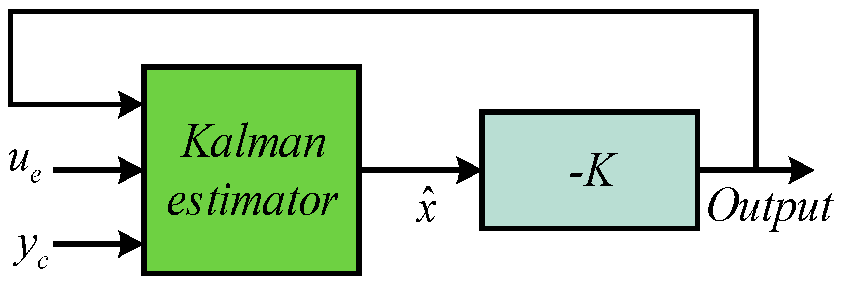
11.3. LQG Control Technique

The integration of Kalman filter with an LQR controller gives rise to an LQG controller. In this technique, Kalman Filter, as well as an LQG controller, can be designed independently of each other. This control scheme is valid for both linear time-invariant systems as well as for linear time-varying systems. LQG control technique facilitates the designing of a linear feedback controller for an uncertain nonlinear control system [79,80,81]. An LQG control structure with a Kalman estimator is shown in Figure 24. Where, u e represents the known input and y c is the estimated noise/disturbance. The Kalman estimator provides the optimal solution to the continuous or discrete estimation problems.

11.3.1. Linear Quadratic Regulator

The linear quadratic regulator (LQR) technique is found optimal for steady as well as transient states [82,83,84]. As the name depicts, this control technique is a combination of linear and quadratic functions, where the dynamics of the system are described by a set of linear equations and the cost of the system is a quadratic function. The cost function parameters are considered critically while designing the controller. LQR algorithm is an automatic approach for finding a suitable state-feedback controller. Pole placement with state feedback controller provides the system with a high degree of freedom and makes it simpler to implement. This method is characteristically steady and it can be employed even if some of the system parameters are unknown. However, exertion in finding the exact weighting factors limits the applications of LQR control scheme. Moreover, it has a discrepancy of tracking accuracy during load changes [83,84,85].

11.3.2. Linear Quadratic Integrator

In linear quadratic integrator (LQI) scheme, cost minimization is considered critically. This technique is implemented for nullifying the steady-state error between actual grid voltage and reference grid voltage during load variations [82]. An integral term used with LQ control is for minimizing the tracking error produced by uncertain disturbances in instantaneous reference voltage. Optimal gains for providing adequate tracking with zero steady-state error are relatively simpler to attain by using this technique. The rapid dynamic response, accurate tracking ability and relatively simpler designing procedure provide this technique a benefit over other techniques. However, complications in extracting the model and phase shift in voltage tracking even in normal operative condition are the major drawbacks of this scheme.

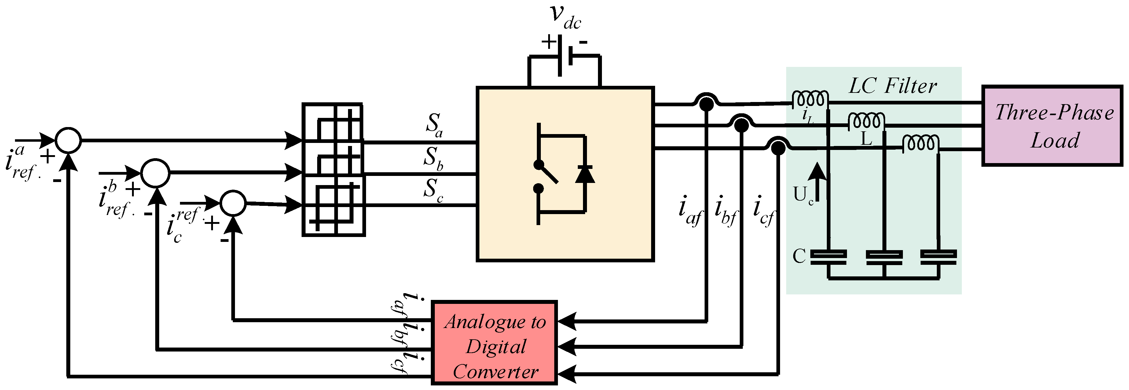
11.4. Hysteresis Control Technique

Hysteresis control is considered as a nonlinear method [86,87,88,89,90,91,92,93]. The hysteresis controllers are used to track the error between the referred and measured currents. Therefore, the gating signals are generated on the basis of this reference tracking. Hysteresis bandwidth is adjusted for error removal in reference tracking. This is an uncomplicated concept and has been used since analog control platforms were intensively used. This technique does not require a modulator; therefore, the switching frequency of an inverter is dependent on the hysteresis bandwidth operating conditions and filter parameters [94]. The major drawback of hysteresis controller is its uncontrolled switching frequency; however, researchers are working on improving this controller and several works are presented and several techniques are proposed in the literature. Main advances in this technique are direct torque control (DTC) [87,88,95,96] and direct power control (DPC) [97,98,99]. In DPC, active and reactive powers are directly controlled, however, in DTC torque and flux of the system are controlled. Error signals are produced by hysteresis controllers and drive signals are generated by the look-up according to the magnitude of the error signals. Hysteresis controllers require very high frequency for constraining the variables in hysteresis band limits, whenever implemented on a digital platform as shown in Figure 25. Moreover, switching losses are very high in this type of controllers. So, Hysteresis controllers are found inappropriate for high power applications.

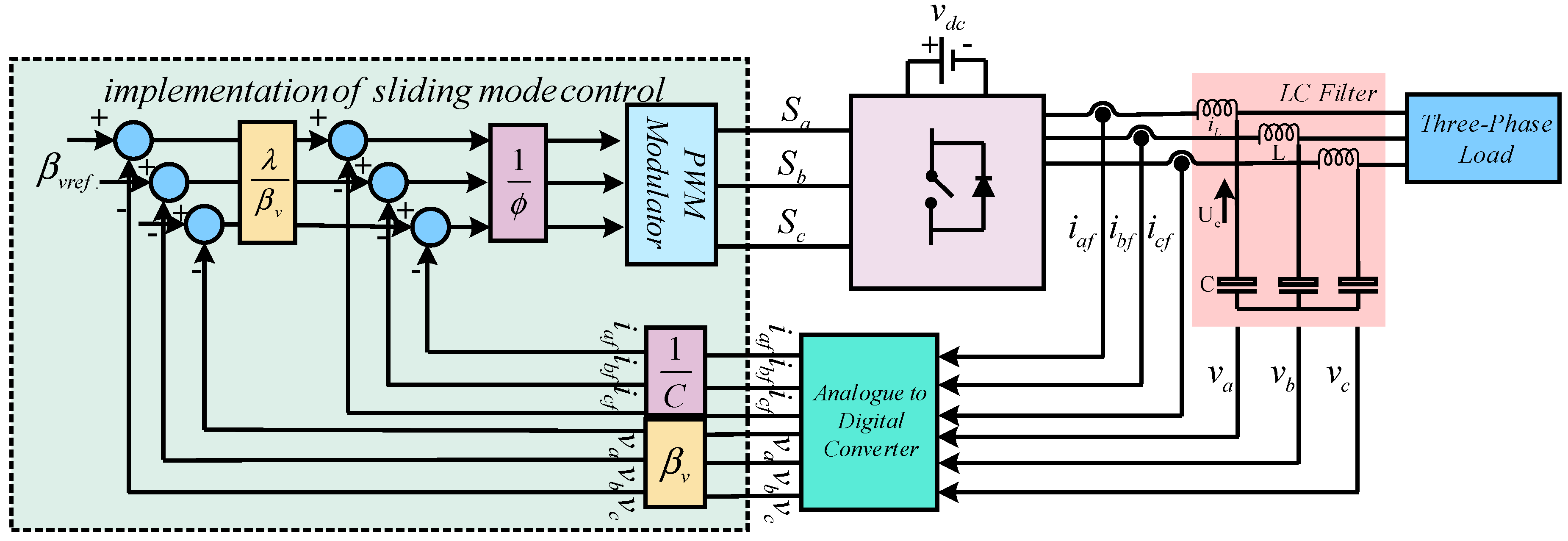
11.5. Sliding Mode Control

The sliding mode control is considered to be an advanced power control technique for the power converters. It fits into the family of adaptive control and variable structure control [100,101,102,103,104]. Sliding mode control is a non-linear technique, whereas it can be instigated to both non-linear as well as linear systems [100]. In Figure 26, a sliding mode control along with SVM/PWM is presented. Where, β v represents the gain, λ is a strictly positive constant and ϕ is a trade-off between the tracking error and smoothing of the control discontinuity. The sliding controller produces the voltage references in a converter for generating the drive signals. A predefined trajectory is executed and the control variable is forced to slide along it [102,103,104]. The robust and stable response is achieved even in the system parameters variation or load disturbances by implementing sliding mode control technique. This controller is more robust and capable of removing the stable error as compared to the classical controllers. However, some drawbacks in implementing a sliding mode control are difficulty in finding a suitable sliding surface and limitation of sampling rate that degrades the performance of SMC will be degraded. Whenever tracking a variable reference, the chattering phenomenon is another drawback of SMC technique. As a result, overall system efficacy is reduced [105,106].

11.6. Partial Feedback Controllers

There are several techniques presented for conversion of non-linear systems to linear systems for their uncomplicated computation. Partial feedback controllers are one of the most effective and forthright techniques for transforming the non-linear systems into the linear ones. By this technique, a system can be converted either partially or fully into a linear system, depends on the system constraints. Linearity in a system is attained by the cancellation of the nonlinearities inside the system. So, these systems can be controlled by using the linear controllers whenever a non-linear system is fully transformed into a linear system i.e., exact feedback linearization method. However, if it is partially converted into a linear system then it is known to be partial feedback linearization. PFL controller is implemented in [104,106,107,108,109]. In PFL, it is difficult to ensure the stability of complicated renewable energy system applications. However, an independent subsystem can be obtained from PFL for constraining the extensive use of this method. Moreover, in order to deal with these problems, exact feedback linearization (EFL) is a forthright and model-based technique for scheming nonlinear control techniques. EFL receipts the built-in nonlinearity characteristic of the system under deliberation and consents the conversion of a nonlinear structure into a linear one, algebraically. EFL removes nonlinearities of a system through nonlinear feedback, as a result, the transformed system is not reliant on an operating point.

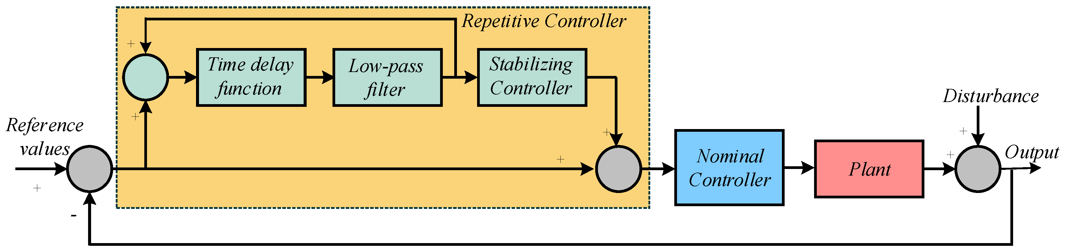
11.7. Repetitive Control

The plug-in scheme (PIS) and internal model (IM) principle are the basic concepts of repetitive control (RC). RC uses an IMP which is in correspondence to the model of a periodic signal. In order to derive this model, trigonometric Fourier series expansion is used. If the model of reference is fed into the closed loop path, optimal reference tracking can be obtained. Moreover, it is found robust against disturbances and has the ability to reject them. RC mostly deals with periodic signals. Closed loop behavior of the system and Magnitude response of the IM are the core factors used for analyzing the performance of the repetitive controller in case of frequency variation or any other uncertainty in the system. Both these factors indicate the performance sagging in case of variation or uncertainty in the reference signal. In presence of a periodic disturbance, RC intends to attain zero tracking error when a periodic or a constant command is referred to it. RC has an ability to locate an error, a time-period before and fine-tunes the next command according to the feedback control system for eliminating the observed error. However, it lacks the ability to handle physical noise. For this purpose, an LPF can be used. Kalman’s filtering approach is also noticeable to remove this noise [27,110,111,112,113]. The general structure of a repetitive controller is shown in Figure 27.

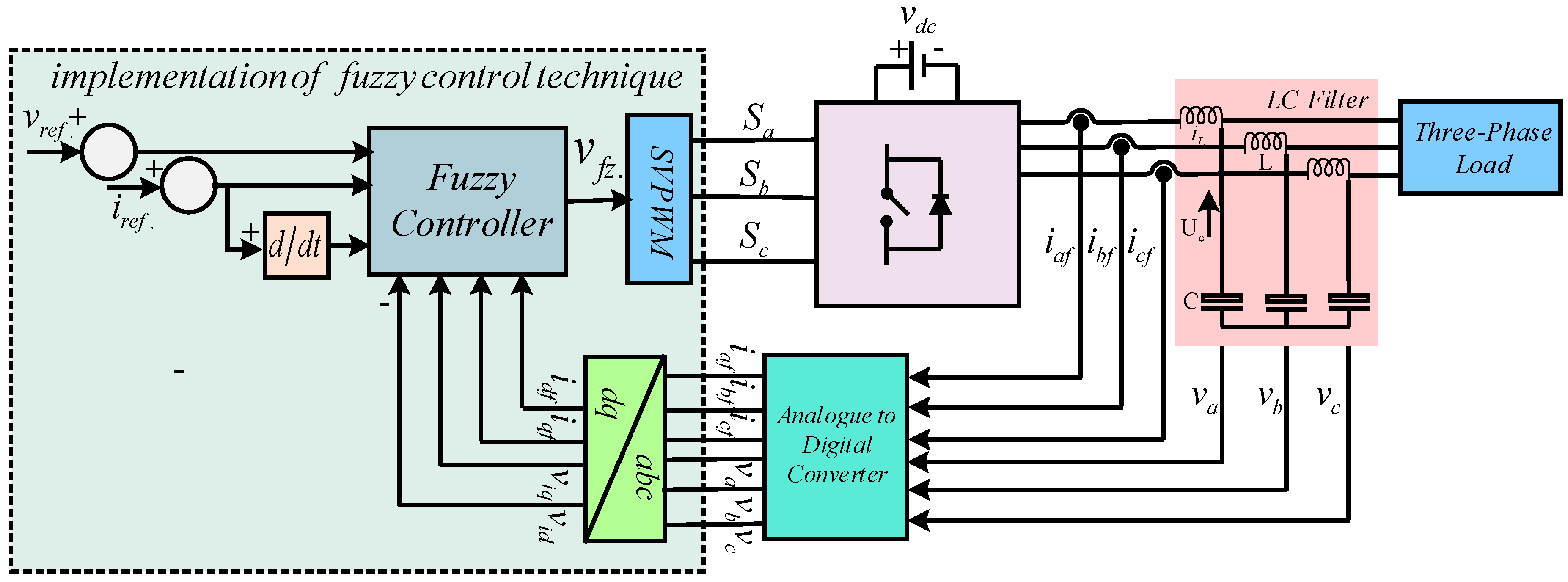
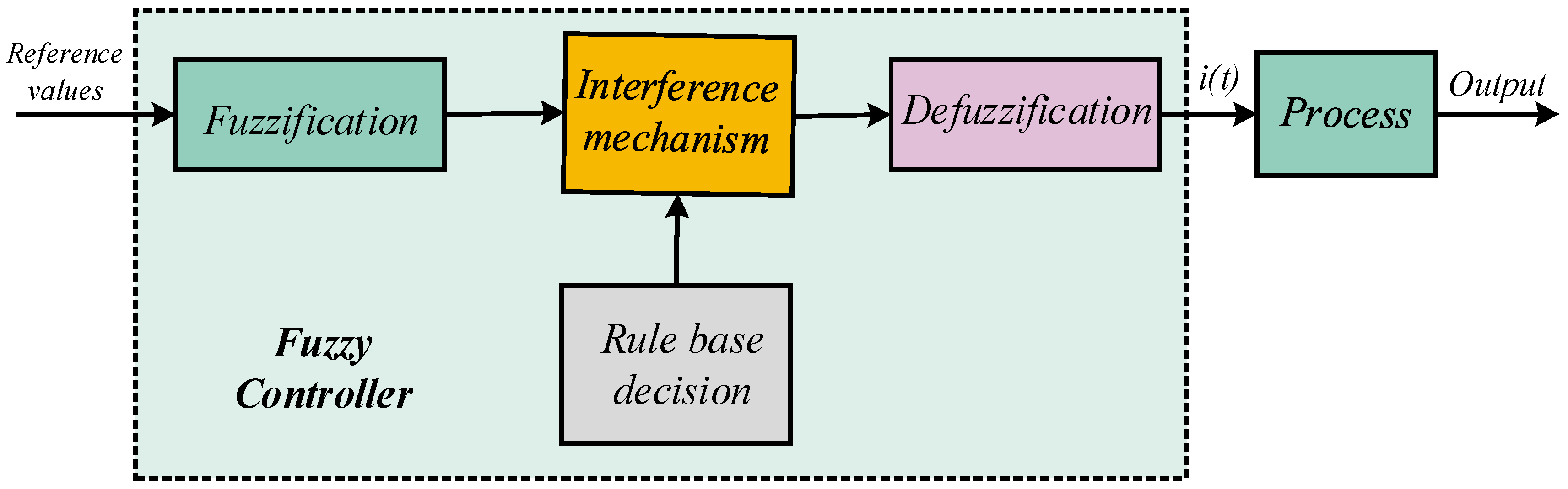
11.7.1. Fuzzy Control

This control technique belongs to the family of intelligent control systems. The PI controller is replaced by a fuzzy logic controller in this technique as shown in Figure 28. Where, v f z . is the fuzzified output voltage. However, its block diagram is shown in Figure 29. In a fuzzy controller, the tracking error of load current and its derivative are given as the input. This controller design is dependent on the awareness, knowledge, skills and experience of the converter designer in terms of functions involvement. Due to non-linear nature of the power converters, the system can be stabilized in case of parameters variation even if the exact model of the converter is unknown. Fuzzy logic controllers are also categorized as non-linear controllers and probably the best controllers amongst the repetitive controllers [113,114,115,116]. However, strong assumptions and adequate experience are required in fuzzification of this controller. As it is dependent on the system input and draw conclusions according to the set of rules assigned to them during the process of their modeling and designing.

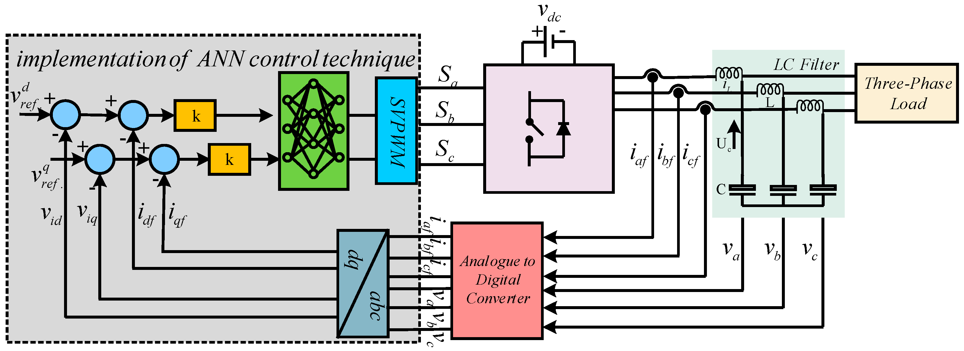
11.7.2. Artificial Neural Network Control

The Artificial neural network (ANN) controllers are the fundamental form of the controllers based on the human-thinking mode. It consists of a number of artificial neurons to behave as a biological human brain. The reference tracking error signals are given through a suitable gain or a scaling factor (S) as input to the ANN for generating the switching signals into the power converters. This approach is used for achieving the constant switching operation in power converters. ANN can be used in both online as well offline modes while operating it on system control. It has high tolerance level to faults because of its ability to estimate the function mapping. Its topology is shown in Figure 30.
Fuzzy and ANN can be combined to achieve an optimal control performance in a power converter [113,114,115]. ANN does not need a converter model for its operation, however, the operational behavior of a power converter should be precisely known to the designer/operator while designing the ANN control system.

11.8. Robust Controllers

In robust control theory, a control system vigorous against uncertainties and disturbances is offered. The basic aim is to attain the stability in case of inadequate modeling. All the descriptions, criteria and limitations should be appropriately defined in order to get robust control. This controller guarantees the stability and high performance of closed-loop system even in multivariable systems [117].

11.8.1. H-Infinity Controllers

The expression H∞ control originates from the term mathematical space on which the optimization takes place: H∞ is considered as a space of matrix-valued functions that are investigative and confined in the open right-half of the complex plane. In this type of control system, first of all, the control problem is formulated and then mathematical optimization is implemented i.e., selection of the best element according to criterion from the set of obtainable alternatives. H-infinity control techniques are generally pertinent for the multivariable systems. The impact of a perturbation can be reduced by using H-infinity control techniques in a closed loop system subject to the problem formulation. The impact can be measured either in terms of performance or stabilization of the system. However, modeling of the system should be well-defined for implementation of these control techniques. Moreover, H-infinity control techniques have another discrepancy of high computational complications. In case of non-linear systems limitations, the control system cannot handle them well and response time also increases [118]. However, these controllers are implemented and well defined in [111,112,119].

11.8.2. μ-Synthesis Controllers

Mu-synthesis is based on the multivariable feedback control technique, which is used to handle the structured as well as unstructured disturbances in the system. Where μ mentions the singular value that is reciprocal of the multivariable stability margin. The basic purpose is to mechanize the synthesis of multivariable feedback controllers that are insensitive to uncertainties of the plant and be able to attain the anticipated performance objectives. This method is well described in [120,121].

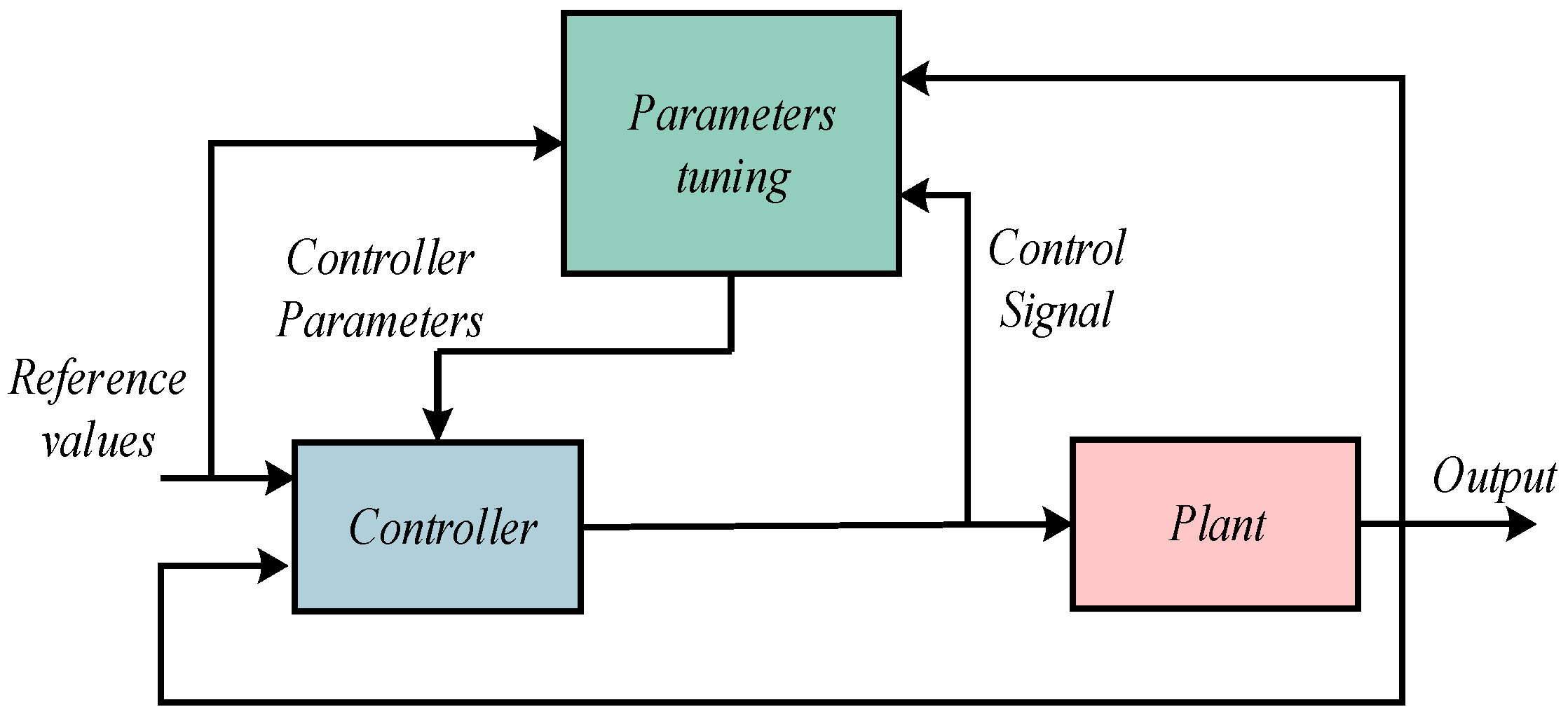
11.9. Adaptive Controllers

An adaptive controller is designed to have the ability of self-tuning, i.e., to regulate itself spontaneously according to variations in the system parameters. It does not require initial conditions, system parameters or limitations for its implementation due to its ability to modify the control law according to system requirements. Recursive least squares and Gradient descent are two most commonly known technique for parameters estimation in adaptive controllers. The structure of a typical adaptive controller is shown in Figure 31. In the literature, some credible research articles and state-of-the-art techniques for adaptive controllers are found in [14,37,53,55,113,122,123,124,125]. These controllers are applicable for both dynamic as well as static processes. However, the complicated computational process leads to exertion in its implementation.

11.10. Predictive Controllers

Predictive controllers are commenced as a propitious control technique for electronics inverters. The system model is considered critically and then imminent behavior of the control variables is predicted conferring to the specified criterion. It is an uncomplicated technique and can handle multivariable systems efficiently. Moreover, it can handle the system with several limitations or non-linearities. It is generally preferred due to its prompt static as well as dynamic response and ability to handle stable errors. However, its computational analysis is complex as compared to classical controllers. It is further categorized into Deadbeat control and Model Predictive control. It can refer to literature [105,125,126,127] for predictive controllers. A comparison of predictive control techniques on basis of their pros. and cons. is described in Table 2.

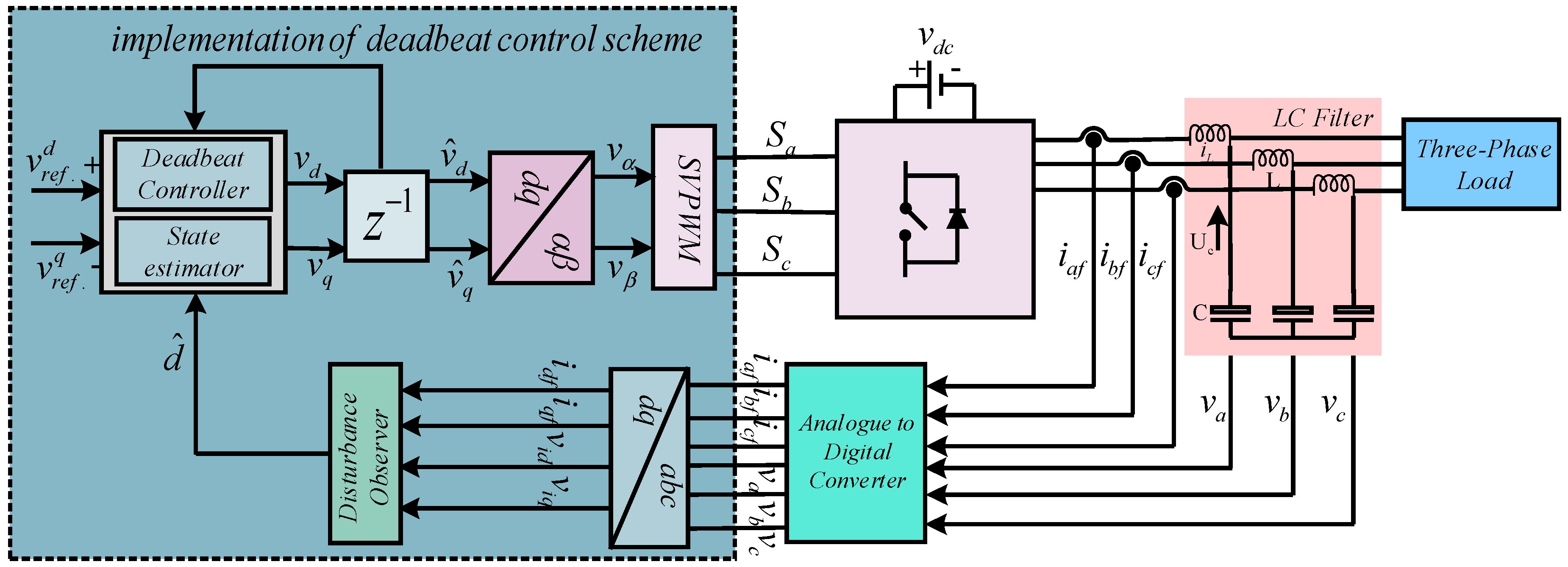
11.10.1. Deadbeat Control

Deadbeat control technique is the most authentic, competent and attractive technique in terms of low THD value, frequency as well as rapid transient response. Differential equations are derived and discretized in this type of control system for controlling the dynamic behavior of the system. The control signal is predicted for the new sampling period for attaining the reference value. Its effective dynamic performance and high bandwidth simplify the current control for this type of controller. Error compensation is a specialty of a deadbeat controller. However, its major discrepancy is its sensitivity for network parameters and accurate mathematical filter modeling [13,54,56,128,129,130,131,132,133,134,135]. Its topology is shown in Figure 32, where a disturbance observer, a state estimator and a digital deadbeat controller are used to control the voltage and current of a VSI. The coefficient d ^ represents the output of disturbance observer comprises of current and voltage. However, v ^ d and v ^ q represents the controlled voltage across d-axis and q-axis respectively.

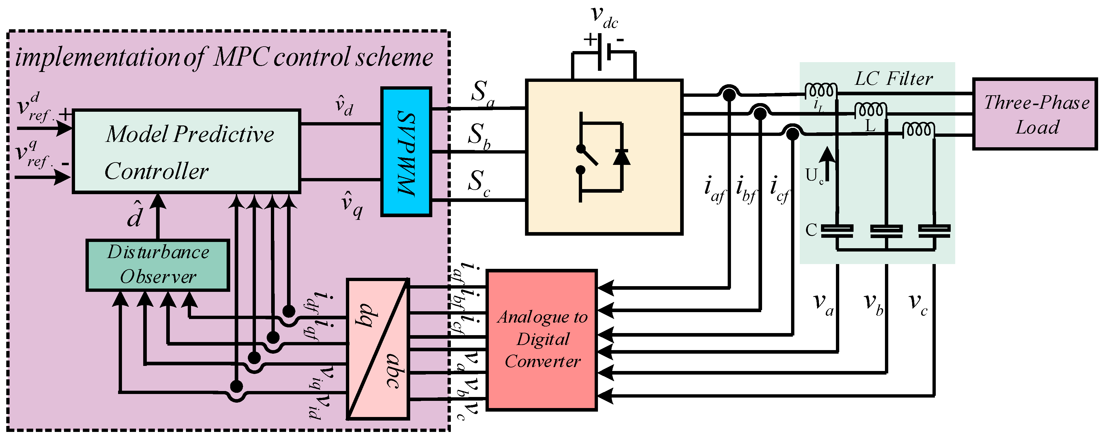
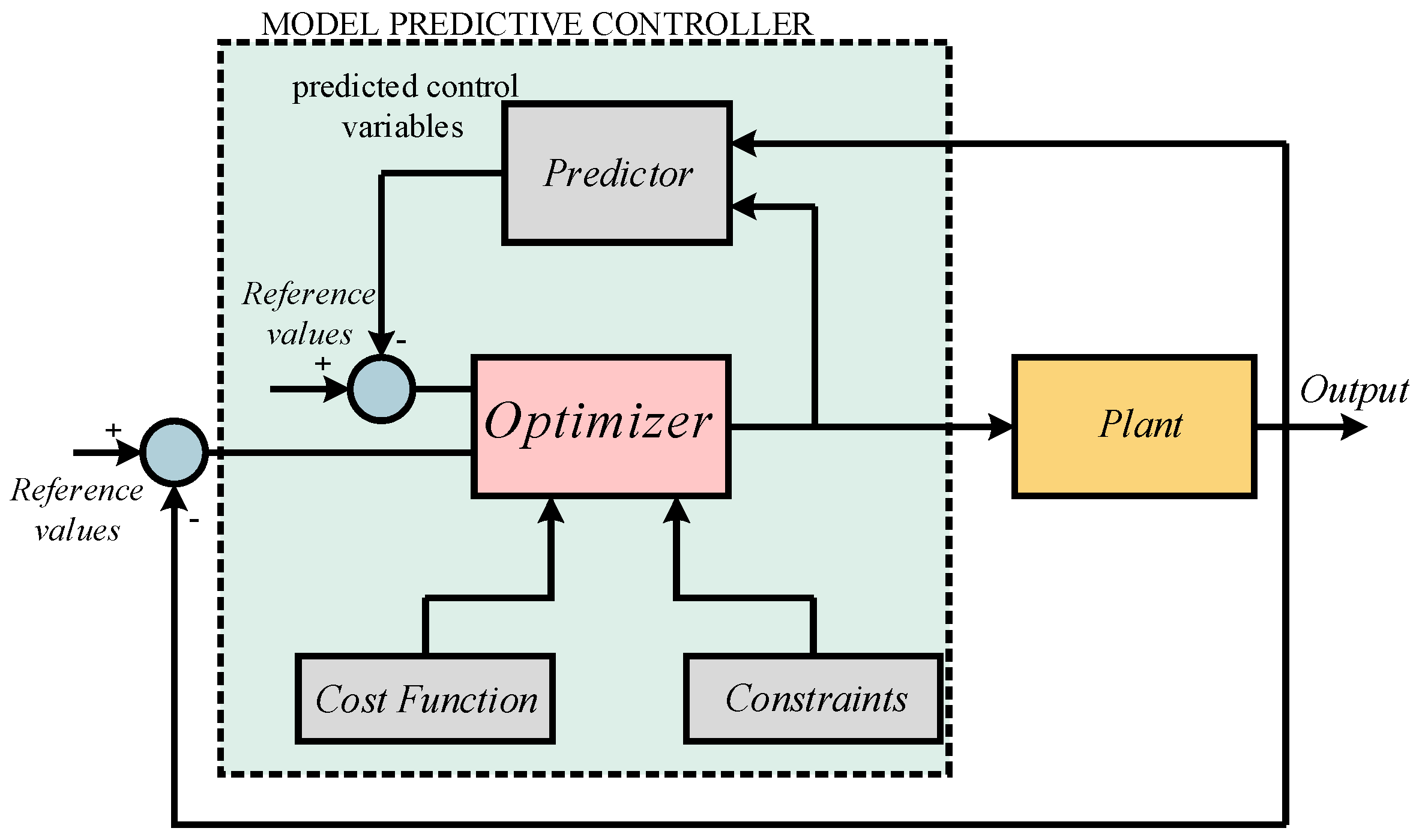
11.10.2. Model Predictive Control

As the name depicts, a model of the system is used to predict the behavior of the system in model predictive control (MPC) technique. A cost function criterion is defined in this type of control system, which can be minimized for optimal control actions. The controller adapts the optimal switching states according to the cost function criterion. Forecast error can be lessened for current tracking implementing. Moreover, system limitations and non-linearities, as well as multiple inputs and output systems, are handled well by MPC. Control actions of the present state are considered in order to predict the control actions of the system in the next state. Like deadbeat control, it is also found sensitive to system parameter variations [136,137,138,139,140,141,142,143,144,145,146,147]. The topology for implementation of MPC on VSI is shown in Figure 33, whereas, its control schematic is depicted in Figure 34.

11.11. Iterative Learning Scheme

Iterative Learning Scheme (ILS) is a complicated but authentic technique for attaining zero tracking error. In this scheme, each control command is executed and the system is examined and then adjusted accordingly before each repetition. Highly accurate modeling of the system is essential for the implementation of ILS; therefore, its designing technique is relatively more complicated than other schemes. ILS is capable of removing the tracking error caused by the periodic disturbances. The next cycle is predicted by considering the learning gain, system adjustment in z-transform, tracking error at each repetition, control function of the designed controller and the error function between two consecutive iterations.

12. Comparative Analysis and Future Research Goals

VSIs are specially designed for converting DC to three-phase AC, therefore, control strategies must be according to the three-leg three-phase power inverters. However, for MLIs, the control strategies must be inherited from three-leg three-phase power inverters. The control policies of VSIs in stand-alone mode can be categorized into numerous categories depending upon similar and dissimilar considerations. Considering the PWM, VSIs can be classified into two categories i.e., carrier-based modulation and carrier-less modulation. The carrier-based modulation schemes such as Selective Harmonic Elimination (SHE), 3D SVPWM, Sinusoidal Pulse Width Modulation (SPWM) and Minimum-Loss Discontinuous PWM (MLDPWM) based PWM techniques have attained significant consideration due to their constant switching frequency.
SPWM offers constant switching frequency and flexible control schemes; nevertheless, one major disadvantage of this technique is the compact efficacy of the DC voltage [148]. The 3D-SVPWM delivers an adequate DC bus utilization and a standardized load harmonic curvature as compared to the SPWM technique. However, it is complex in nature to be implemented on the digital devices. Correspondingly, the SHE-PWM suggests a flexible controller by considering the switching angle. However, the real-time enactment of this carrier-based modulation is quite difficult. The capability of the MLDPWM under nonlinear and unbalanced conditions is found relatively admissible; however, its real-time execution is found very much circuitous. However, the carrier-less modulation approaches such as flux vector and hysteresis provide a rapid-dynamic response [149]. But, they suffer from variable switching frequency [91]. Additionally, they require composite switching tables for their implementation.
The conventional PI controllers encounter problems to eliminate the steady-state error. In order to solve this problem, a PR controller is commonly used in the stationary reference frame for regulating the output voltages of the VSIs due to its sophisticated explication in eliminating the steady-state error, while controlling sinusoidal signals. Additionally, it is competent in eliminating selective harmonic uncertainties.
It is also taken into consideration that the PR controller perceives the resonant frequency to offer gains at specific frequencies. Thus, the resonant frequency should be synchronized with the frequency of the microgrid. Hence, it can be said that it is very sensitive with respect to the variations in system frequency. The PI controller is also extensively used in the dqo frame and performs robustly with pure DC signals. Though, in order to allocate the control variables from the abc to the dqo frame, the phase angle of the microgrid should be known. Likewise, using cross-coupling and voltage feedforward terms are the secondary problems in implementing this method.
In the stand-alone operating mode, VSIs primarily controls the power transfer, voltage and frequency of the system. Nevertheless, power quality can be enhanced by offering a suitable control technique in the inverter-based type DGs. As in VSIs, the auxiliary services for improvement in power quality embedded in the control assembly. In case of VSIs, compensation of unbalanced voltage, a lower value for total harmonic distortion, harmonic power-sharing schemes, power sharing between active/reactive powers, imbalance power, active/reactive power control and augmentation in power quality are critically considered and embedded in control schemes. VSIs are also applied on several applications in microgrid systems, extensively, for improving the power quality. This power control strategy is presented in [38]. However, a comprehensive review of various control strategies for microgrids is described in [150]. Moreover, using modular multilevel inverters can improve the modularity and scalability to meet reference voltage levels, efficiency in high power applications, reduction in harmonics in high voltage applications and size of passive filters as well as no requirement for dc-link capacitors [151].
In Table 3, different types of filters are suggested by various researchers based on the control systems. However, it is significant to use L-filters for low power applications having a simple design, nevertheless, L-filters are not found suitable in resonance state as well as for high power applications. So, LCL-filter is highly preferred in aforementioned system characteristics. The designing of this filter is comparatively complicated due to a few constrictions related to the system stability. The accuracy in designing and modeling of the system leads to better performance against resonance and harmonics. Nevertheless, the choice should be made according to the customer’s demand. The prime parameters should be chosen on the basis of system condition and intended tasks to be performed by the system. Afterward, the designing of power system and control system parameters should be finalized.
This corresponding study incorporates the advantages and disadvantages of each controller in terms of stability, rapid response time, harmonic elimination, the nonlinearity of the system, unbalanced compensation and robustness against parameter variation. Various suitable control schemes for different types of VSIs are documented in this paper. However, their implementations for power generation and power quality improvement are still not perfect simultaneously. Moreover, each controller has its own benefits and obstructions. Therefore, it is not easy to decide that which control scheme is better than the others. These are significant subjects for the future research. On the basis of the analysis of former publications, appended research is suggested to be carried out in the aforementioned area.
Regardless of the several investigations in this field, none of the proposed control techniques can be selected as an immaculate solution to meet al.l the requirements of power quality, i.e., harmonic/reactive/imbalance power-sharing and voltage unbalanced/harmonic/swell/sag and Interruption compensation at the same time. Therefore, further research should be focused on the novel power-electronics topologies to fulfill all aforementioned necessities simultaneously.
Three-phase three-wire VSIs are now a well-developed and mature research topic with respect to their hierarchical control. But on the other hand, control hierarchies are not as well established for ML-VSIs, as for three-phase three-wire VSIs. It may be beneficial to consider ML-VSI system, as well as the primary, secondary and tertiary stages, whenever a control scheme is to be designed.
Substantially, a lot of work is to be done for exploiting the new control approaches for ML-VSIs. In order to achieve enhanced performance, it is compulsory to use some innovative techniques such as robust, MPC and LQR control techniques.
It is also observed through a number of studies that coupling among the phases is neglected whenever controlling an ML-VSI by means of a conventional PI controller, which results in a reduction of the system’s robustness. Hence, it can also be beneficial to implement decoupled phase voltage control to realize the referred response in time domain. A comparison of the credible research articles found in literature with respect to their control techniques, modulation schemes, control parameters, loop characteristics, employed filters and applications is described in Table 3.

13. Conclusions

On the basis of research, conventional multilevel inverter topologies given in the previous sections, general and asymmetrically constituted ML-VSIs have been also reviewed in this paper. Several new hybrid topologies can be designed through the combinations of three main MLI topologies. Besides the combination of topologies, the trade-offs in MLI structures can be dealt by using H-MLIs that is formed using different DC source levels in inverter cells. PWM strategies that generate switching frequency at fundamental frequency are also introduced for H-MLIs for the switching devices of the higher voltage modules to operate at high frequencies only during some inverting instants. Due to numerous applications of conventional MLIs and flexibility to design the hybrid MLI topologies, this paper cannot cover all utilizations with MLIs but the authors intend to provide a useful basis to define the most proper control schemes and applications. In addition to these, the fundamental design and control principles of MLIs have been introduced as a result of a detailed literature survey. This paper has been destined to provide a reference to readers and the results given in this paper can also be extended with experimental studies.

Acknowledgments

The National Natural Science Foundation of China supported this research work under Grant No. 61374155. Moreover, the Specialized Research Fund for the Doctoral Program of Higher Education PR China under Grant No. 20130073110030 is highly acknowledged.

Author Contributions

Sohaib proposed the idea for writing the manuscript. Wang suggested the literature and supervised in writing the manuscript. Mazhar helped Sohaib in writing and formatting. Sarwar helped in modifying the figures and shared the summary of various credible articles to be included in this manuscript.

Conflicts of Interest

The authors declare no conflict of interest.

References

  1. Blaabjerg, F.; Teodorescu, R.; Liserre, M.; Timbus, A.V. Overview of control and grid synchronization for distributed power generation systems. IEEE Trans. Ind. Electron. 2006, 53, 1398–1409. [Google Scholar] [CrossRef]
  2. European Commission Directorate-General for Energy. DG ENER Work in the Paper—The Future Role and Challenges of Energy Storage; European Commission Directorate-General for Energy: Brussel, Belgium, 2013. [Google Scholar]
  3. Loh, P.C.; Newman, M.J.; Zmood, D.N.; Holmes, D.G. A comparative analysis of multiloop voltage regulation strategies for single and three-phase UPS systems. IEEE Trans. Power Electron. 2003, 18, 1176–1185. [Google Scholar]
  4. Kassakian, J.G.; Schlecht, M.F.; Verghese, G.C. Principles of Power Electronics; Addison-Wesley: Reading, PA, USA, 1991; Volume 1991. [Google Scholar]
  5. Mohan, N.; Undeland, T.M. Power Electronics: Converters, Applications, and Design; John Wiley & Sons: New Delhi, India, 2007. [Google Scholar]
  6. Abdel-Rahim, N.M.; Quaicoe, J.E. Analysis and design of a multiple feedback loop control strategy for single-phase voltage-source UPS inverters. IEEE Trans. Power Electron. 1996, 11, 532–541. [Google Scholar] [CrossRef]
  7. Lee, T.-S.; Chiang, S.-J.; Chang, J.-M. H/sub/spl infin//loop-shaping controller designs for the single-phase UPS inverters. IEEE Trans. Power Electron. 2001, 16, 473–481. [Google Scholar]
  8. Willmann, G.; Coutinho, D.F.; Pereira, L.F.A.; Libano, F.B. Multiple-loop H-infinity control design for uninterruptible power supplies. IEEE Trans. Ind. Electron. 2007, 54, 1591–1602. [Google Scholar] [CrossRef]
  9. Kawabata, T.; Miyashita, T.; Yamamoto, Y. Dead beat control of three phase PWM inverter. IEEE Trans. Power Electron. 1990, 5, 21–28. [Google Scholar] [CrossRef]
  10. Ito, Y.; Kawauchi, S. Microprocessor based robust digital control for UPS with three-phase PWM inverter. IEEE Trans. Power Electron. 1995, 10, 196–204. [Google Scholar] [CrossRef]
  11. Cho, J.-S.; Lee, S.-Y.; Mok, H.-S.; Choe, G.-H. Modified deadbeat digital controller for UPS with 3-phase PWM inverter. In Proceedings of the Thirty-Fourth IAS Annual Meeting, Conference Record of the 1999 IEEE Industry Applications Conference, Phoenix, AZ, USA, 3–7 October 1999; Volume 4. [Google Scholar]
  12. Lee, T.S.; Tzeng, K.S.; Chong, M.S. Robust controller design for a single-phase UPS inverter using μ-synthesis. IEE Proc. Electr. Power Appl. 2004, 151, 334–340. [Google Scholar] [CrossRef]
  13. Tahir, S.; Wang, J.; Kaloi, S.G.; Hussain, M. Robust digital deadbeat control design technique for 3 phase VSI with disturbance observer. IEICE Electron. Express 2017, 14, 20170351. [Google Scholar] [CrossRef]
  14. Jung, J.-W.; Vu, N.T.-T.; Dang, D.Q.; Do, T.D.; Choi, Y.S.; Choi, H.H. A three-phase inverter for a standalone distributed generation system: Adaptive voltage control design and stability analysis. IEEE Trans. Energy Convers. 2014, 29, 46–56. [Google Scholar] [CrossRef]
  15. Bogosyan, S. Recent advances in renewable energy employment. IEEE Ind. Electron. Mag. 2009, 3, 54–55. [Google Scholar] [CrossRef]
  16. Liserre, M.; Sauter, T.; Hung, J.H. Future energy systems: Integrating renewable energy sources into the smart power grid through industrial electronics. IEEE Ind. Electron. Mag. 2010, 4, 18–37. [Google Scholar] [CrossRef]
  17. Kim, M.-Y.; Song, Y.-U.; Kim, K.-H. The advanced voltage regulation method for ULTC in distribution systems with DG. J. Electr. Eng. Technol. 2013, 8, 737–743. [Google Scholar] [CrossRef]
  18. Mokhtarpour, A.; Shayanfar, H.; Bathaee, S.M.T.; Banaei, M.R. Control of a single phase unified power quality conditioner-distributed generation-based input output feedback linearization. J. Electr. Eng. Technol. 2013, 8, 1352–1364. [Google Scholar] [CrossRef]
  19. He, J.; Li, Y.W. An enhanced microgrid load demand sharing strategy. IEEE Trans. Power Electron. 2012, 27, 3984–3995. [Google Scholar] [CrossRef]
  20. Marwali, M.N.; Jung, J.-W.; Keyhani, A. Stability analysis of load sharing control for distributed generation systems. IEEE Trans. Energy Convers. 2007, 22, 737–745. [Google Scholar] [CrossRef]
  21. Zhang, Y.; Yu, M.; Liu, F.; Kang, Y. Instantaneous current-sharing control strategy for parallel operation of UPS modules using virtual impedance. IEEE Trans. Power Electron. 2013, 28, 432–440. [Google Scholar] [CrossRef]
  22. Vechiu, I.; Curea, O.; Camblong, H. Transient operation of a four-leg inverter for autonomous applications with unbalanced load. IEEE Trans. Power Electron. 2010, 25, 399–407. [Google Scholar] [CrossRef]
  23. Kasal, G.K.; Singh, B. Voltage and frequency controllers for an asynchronous generator-based isolated wind energy conversion system. IEEE Trans. Energy Convers. 2011, 26, 402–416. [Google Scholar] [CrossRef]
  24. Nian, H.; Zeng, R. Improved control strategy for stand-alone distributed generation system under unbalanced and non-linear loads. IET Renew. Power Gener. 2011, 5, 323–331. [Google Scholar] [CrossRef]
  25. Karimi, H.; Nikkhajoei, H.; Iravani, R. Control of an electronically-coupled distributed resource unit subsequent to an islanding event. IEEE Trans. Power Deliv. 2008, 23, 493–501. [Google Scholar] [CrossRef]
  26. Karimi, H.; Yazdani, A.; Iravani, R. Robust control of an autonomous four-wire electronically-coupled distributed generation unit. IEEE Trans. Power Deliv. 2011, 26, 455–466. [Google Scholar] [CrossRef]
  27. Escobar, G.; Valdez, A.A.; Leyva-Ramos, J.; Mattavelli, P. Repetitive-based controller for a UPS inverter to compensate unbalance and harmonic distortion. IEEE Trans. Ind. Electron. 2007, 54, 504–510. [Google Scholar] [CrossRef]
  28. Yazdani, A. Control of an islanded distributed energy resource unit with load compensating feed-forward. In Proceedings of the 2008 IEEE Power and Energy Society General Meeting-Conversion and Delivery of Electrical Energy in the 21st Century, Pittsburgh, PA, USA, 20–24 July 2008. [Google Scholar]
  29. Dasgupta, S.; Sahoo, S.K.; Panda, S.K. Single-phase inverter control techniques for interfacing renewable energy sources with microgrid—Part I: Parallel-connected inverter topology with active and reactive power flow control along with grid current shaping. IEEE Trans. Power Electron. 2011, 26, 717–731. [Google Scholar] [CrossRef]
  30. Dai, M.; Marwali, M.N.; Jung, J.-W.; Keyhani, A. A three-phase four-wire inverter control technique for a single distributed generation unit in island mode. IEEE Trans. Power Electron. 2008, 23, 322–331. [Google Scholar] [CrossRef]
  31. Delghavi, M.B.; Yazdani, A.N. Islanded-mode control of electronically coupled distributed-resource units under unbalanced and nonlinear load conditions. IEEE Trans. Power Deliv. 2011, 26, 661–673. [Google Scholar] [CrossRef]
  32. Delghavi, M.B.; Yazdani, A.N. An adaptive feedforward compensation for stability enhancement in droop-controlled inverter-based microgrids. IEEE Trans. Power Deliv. 2011, 26, 1764–1773. [Google Scholar] [CrossRef]
  33. Prodanovic, M.; Timothy, C.; Green, T.C. Control and filter design of three-phase inverters for high power quality grid connection. IEEE Trans. Power Electron. 2003, 18, 373–380. [Google Scholar] [CrossRef] [Green Version]
  34. Mattavelli, P.; Escobar, G.; Stankovic, A.M. Dissipativity-based adaptive and robust control of UPS. IEEE Trans. Ind. Electron. 2001, 48, 334–343. [Google Scholar] [CrossRef]
  35. Valderrama, G.E.; Stankovic, A.M.; Mattavelli, P. Dissipativity-based adaptive and robust control of UPS in unbalanced operation. IEEE Trans. Power Electron. 2003, 18, 1056–1062. [Google Scholar] [CrossRef]
  36. Escobar, G.; Mattavelli, P.; Stankovic, A.M.; Valdez, A.A.; Leyva-Ramos, J. An adaptive control for UPS to compensate unbalance and harmonic distortion using a combined capacitor/load current sensing. IEEE Trans. Ind. Electron. 2007, 54, 839–847. [Google Scholar] [CrossRef]
  37. Do, T.D.; Leu, V.Q.; Choi, Y.-S.; Choi, H.H.; Jung, J.-W. An adaptive voltage control strategy of three-phase inverter for stand-alone distributed generation systems. IEEE Trans. Ind. Electron. 2013, 60, 5660–5672. [Google Scholar] [CrossRef]
  38. Rasheduzzaman, M.; Mueller, J.; Kimball, J.W. Small-signal modeling of a three-phase isolated inverter with both voltage and frequency droop control. In Proceedings of the 2014 Twenty-Ninth Annual IEEE Applied Power Electronics Conference and Exposition (APEC), Fort Worth, TX, USA, 16–20 March 2014. [Google Scholar]
  39. Rodriguez, J.; Lai, J.-S.; Peng, F.Z. Multilevel inverters: A survey of topologies, controls, and applications. IEEE Trans. Ind. Electron. 2002, 49, 724–738. [Google Scholar] [CrossRef]
  40. Nabae, A.; Takahashi, I.; Akagi, H. A new neutral-point-clamped PWM inverter. IEEE Trans. Ind. Appl. 1981, 5, 518–523. [Google Scholar] [CrossRef]
  41. Franquelo, L.G.; Rodriguez, J.; Leon, J.I.; Kouro, S.; Portillo, R.; Prats, M.A.M. The age of multilevel converters arrives. IEEE Ind. Electron. Mag. 2008, 2, 28–39. [Google Scholar] [CrossRef]
  42. Lai, J.-S.; Peng, F.Z. Multilevel converters—A new breed of power converters. IEEE Trans. Ind. Appl. 1996, 32, 509–517. [Google Scholar]
  43. Patel, H.S.; Hoft, R.G. Generalized techniques of harmonic elimination and voltage control in thyristor inverters: Part I—Harmonic elimination. IEEE Trans. Ind. Appl. 1973, 3, 310–317. [Google Scholar] [CrossRef]
  44. Khomfoi, S.; Tolbert, L.M. Multilevel power converters. In Power Electronics Handbook; Elsevier/Academic Press: Burlington, VT, USA, 2007; pp. 451–482. [Google Scholar]
  45. Zhang, R.; Prasad, V.H.; Boroyevich, D.; Lee, F.C. Three-dimensional space vector modulation for four-leg voltage-source converters. IEEE Trans. Power Electron. 2002, 17, 314–326. [Google Scholar] [CrossRef]
  46. Lohia, P.; Mishra, M.K.; Karthikeyan, K.; Vasudevan, K. A minimally switched control algorithm forthree-phase four-leg VSI topology tocompensate unbalanced and nonlinear load. IEEE Trans. Power Electron. 2008, 23, 1935–1944. [Google Scholar] [CrossRef]
  47. Zhong, Q.-C.; Liang, J.; Weiss, G.; Feng, C.M.; Green, T.C. H∞ Control of the Neutral Point in Four-Wire Three-Phase DC–AC Converters. IEEE Trans. Ind. Electron. 2006, 53, 1594–1602. [Google Scholar] [CrossRef]
  48. Liang, J.; Green, T.C.; Feng, C.; Weiss, C. Increasing voltage utilization in split-link, four-wire inverters. IEEE Trans. Power Electron. 2009, 24, 1562–1569. [Google Scholar] [CrossRef]
  49. Miret, J.; Camacho, A.; Castilla, M.; de Vicuña, L.G.; Matas, J. Control scheme with voltage support capability for distributed generation inverters under voltage sags. IEEE Trans. Power Electron. 2013, 28, 5252–5262. [Google Scholar] [CrossRef]
  50. Liu, Z.; Liu, J.; Zhao, Y. A unified control strategy for three-phase inverter in distributed generation. IEEE Trans. Power Electron. 2014, 29, 1176–1191. [Google Scholar] [CrossRef]
  51. Li, Y.; Jiang, S.; Cintron-Rivera, J.G.; Peng, F.Z. Modeling and control of quasi-Z-source inverter for distributed generation applications. IEEE Trans. Ind. Electron. 2013, 60, 1532–1541. [Google Scholar] [CrossRef]
  52. Ebadi, M.; Joorabian, M.; Moghani, J.S. Voltage look-up table method to control multilevel cascaded transformerless inverters with unequal DC rail voltages. IET Power Electron. 2014, 7, 2300–2309. [Google Scholar] [CrossRef]
  53. Eren, S.; Pahlevani, M.; Bakhshai, A.; Jain, P. An adaptive droop DC-bus voltage controller for a grid-connected voltage source inverter with LCL filter. IEEE Trans. Power Electron. 2015, 30, 547–560. [Google Scholar] [CrossRef]
  54. Abu-Rub, H.; Guzinski, J.; Krzeminski, Z.; Toliyat, H.A. Predictive current control of voltage-source inverters. IEEE Trans. Ind. Electron. 2004, 51, 585–593. [Google Scholar] [CrossRef]
  55. Espi, J.M.; Castello, J.; Garcia-Gil, R.; Garcera, G.; Figueres, E. An adaptive robust predictive current control for three-phase grid-connected inverters. IEEE Trans. Ind. Electron. 2011, 58, 3537–3546. [Google Scholar] [CrossRef]
  56. Moreno, J.C.; Espi Huerta, J.M.; Gil, R.G.; Gonzalez, S.A. A robust predictive current control for three-phase grid-connected inverters. IEEE Trans. Ind. Electron. 2009, 56, 1993–2004. [Google Scholar] [CrossRef]
  57. Ahmed, K.H.; Massoud, A.M.; Finney, S.J.; Williams, B.W. A modified stationary reference frame-based predictive current control with zero steady-state error for LCL coupled inverter-based distributed generation systems. IEEE Trans. Ind. Electron. 2011, 58, 1359–1370. [Google Scholar] [CrossRef]
  58. Miveh, M.R.; Rahmat, M.F.; Ghadimi, A.A.; Mustafa, M.W. Control techniques for three-phase four-leg voltage source inverters in autonomous microgrids: A review. Renew. Sustain. Energy Rev. 2016, 54, 1592–1610. [Google Scholar] [CrossRef]
  59. Chen, H. Research on the control strategy of VSC based HVDC system supplying passive network. In Proceedings of the 2009 PES’09 IEEE Power & Energy Society General Meeting, Calgary, AB, Canada, 26–30 July 2009. [Google Scholar]
  60. Qian, C.; Tang, G.; Hu, M. Steady-state model and controller design of a VSC-HVDC converter based on dq0-axis. Autom. Electr. Power Syst. 2004, 16, 015. [Google Scholar]
  61. Hoffmann, N.; Fuchs, F.W.; Dannehl, J. Models and effects of different updating and sampling concepts to the control of grid-connected PWM converters—A study based on discrete time domain analysis. In Proceedings of the 2011 14th European Conference on Power Electronics and Applications (EPE 2011), Birmingham, UK, 30 August–1 September 2011. [Google Scholar]
  62. Büyük, M.; Tan, A.; Tümay, M.; Bayındır, K.Ç. Topologies, generalized designs, passive and active damping methods of switching ripple filters for voltage source inverter: A comprehensive review. Renew. Sustain. Energy Rev. 2016, 62, 46–69. [Google Scholar] [CrossRef]
  63. Peña-Alzola, R.; Liserre, M.; Blaabjerg, F.; Ordonez, M.; Yang, Y. LCL-filter design for robust active damping in grid-connected converters. IEEE Trans. Ind. Inform. 2014, 10, 2192–2203. [Google Scholar] [CrossRef]
  64. Zhang, C.; Dragicevic, T.; Vasquez, J.C.; Guerrero, J.M. Resonance damping techniques for grid-connected voltage source converters with LCL filters—A review. In Proceedings of the 2014 IEEE International Energy Conference (ENERGYCON), Cavtat, Croatia, 13–16 May 2014; pp. 169–176. [Google Scholar]
  65. Jia, Y.; Zhao, J.; Fu, X. Direct grid current control of LCL-filtered grid-connected inverter mitigating grid voltage disturbance. IEEE Trans. Power Electron. 2014, 29, 1532–1541. [Google Scholar]
  66. Teodorescu, R.; Liserre, M.; Rodriguez, P. Grid Converters for Photovoltaic and Wind Power Systems; John Wiley & Sons: Chichester, UK, 2011; Volume 29. [Google Scholar]
  67. Jalili, K.; Bernet, S. Design of LCL filters of active-front-end two-level voltage-source converters. IEEE Trans. Ind. Electron. 2009, 56, 1674–1689. [Google Scholar] [CrossRef]
  68. Kazmierkowski, M.P.; Malesani, L. Current control techniques for three-phase voltage-source PWM converters: A survey. IEEE Trans. Ind. Electron. 1998, 45, 691–703. [Google Scholar] [CrossRef]
  69. Kumar, K.V.; Michael, P.A.; John, J.P.; Kumar, S.S. Simulation and comparison of SPWM and SVPWM control for three phase inverter. ARPN J. Eng. Appl. Sci. 2010, 5, 61–74. [Google Scholar]
  70. Lim, J.S.; Park, C.; Han, J.; Lee, Y.I. Robust tracking control of a three-phase DC–AC inverter for UPS applications. IEEE Trans. Ind. Electron. 2014, 61, 4142–4151. [Google Scholar] [CrossRef]
  71. Huerta, J.M.E.; Castello, J.; Fischer, J.R.; García-Gil, R. A synchronous reference frame robust predictive current control for three-phase grid-connected inverters. IEEE Trans. Ind. Electron. 2010, 57, 954–962. [Google Scholar] [CrossRef]
  72. Samui, A.; Samantaray, S.R. New active islanding detection scheme for constant power and constant current controlled inverter-based distributed generation. IET Gener. Transm. Distrib. 2013, 7, 779–789. [Google Scholar] [CrossRef]
  73. Yuan, X.; Merk, W.; Stemmler, H.; Allmeling, J. Stationary-frame generalized integrators for current control of active power filters with zero steady-state error for current harmonics of concern under unbalanced and distorted operating conditions. IEEE Trans. Ind. Appl. 2002, 38, 523–532. [Google Scholar] [CrossRef]
  74. Miret, J.; Castilla, M.; Matas, J.; Guerrero, J.M.; Vasquez, J.C. Selective harmonic-compensation control for single-phase active power filter with high harmonic rejection. IEEE Trans. Ind. Electron. 2009, 56, 3117–3127. [Google Scholar] [CrossRef]
  75. Beza, M.; Bongiorno, M. Improved discrete current controller for grid-connected voltage source converters in distorted grids. In Proceedings of the 2012 IEEE Energy Conversion Congress and Exposition (ECCE), Raleigh, NC, USA, 15–20 September 2012. [Google Scholar]
  76. Kandil, M.S.; El-Saadawi, M.M.; Hassan, A.E.; Abo-Al-Ez, K.M. A proposed reactive power controller for DG grid connected systems. In Proceedings of the 2010 IEEE International Energy Conference and Exhibition, Manama, Bahrain, 18–22 December 2010; pp. 446–451. [Google Scholar]
  77. Radwan, A.A.A.; Abdel-Rady, I.M.Y. Power Synchronization Control for Grid-Connected Current-Source Inverter-Based Photovoltaic Systems. IEEE Trans. Energy Convers. 2016, 31, 1023–1036. [Google Scholar] [CrossRef]
  78. Chilipi, R.; Sayari, N.A.; Hosani, K.A.; Beig, A.R. Control scheme for grid-tied distributed generation inverter under unbalanced and distorted utility conditions with power quality ancillary services. IET Renew. Power Gener. 2016, 10, 140–149. [Google Scholar] [CrossRef]
  79. Busada, C.; Jorge, S.G.; Leon, A.E.; Solsona, J. Phase-locked loop-less current controller for grid-connected photovoltaic systems. IET Renew. Power Gener. 2012, 6, 400–407. [Google Scholar] [CrossRef]
  80. Athans, M. The role and use of the stochastic linear-quadratic-Gaussian problem in control system design. IEEE Trans. Autom. Control 1971, 16, 529–552. [Google Scholar] [CrossRef]
  81. Huerta, F.; Pizarro, D.; Cobreces, S.; Rodriguez, F.J.; Giron, C.; Rodriguez, A. LQG servo controller for the current control of LCL grid-connected voltage-source converters. IEEE Trans. Ind. Electron. 2012, 59, 4272–4284. [Google Scholar] [CrossRef]
  82. Hossain, M.A.; Azim, M.I.; Mahmud, M.A.; Pota, H.R. Primary voltage control of a single-phase inverter using linear quadratic regulator with integrator. In Proceedings of the 2015 Australasian Universities Power Engineering Conference (AUPEC), Wollongong, Australia, 27–30 September 2015; pp. 1–6. [Google Scholar]
  83. Ahmed, K.H.; Massoud, A.M.; Finney, S.J.; Williams, B.W. Optimum selection of state feedback variables PWM inverters control. In Proceedings of the IET Conference on Power Electronics, Machines and Drives, York, UK, 2–4 April 2008; pp. 125–129. [Google Scholar]
  84. Xue, M.; Zhang, Y.; Kang, Y.; Yi, Y.; Li, S.; Liu, F. Full feedforward of grid voltage for discrete state feedback controlled grid-connected inverter with LCL filter. IEEE Trans. Power Electron. 2012, 27, 4234–4247. [Google Scholar] [CrossRef]
  85. Lalili, D.; Mellit, A.; Lourci, N.; Medjahed, B.; Boubakir, C. State feedback control of a three-level grid-connected photovoltaic inverter. In Proceedings of the 2012 9th International Multi-Conference on Systems, Signals and Devices (SSD), Chemnitz, Germany, 20–23 March 2012; pp. 1–6. [Google Scholar]
  86. Jaen, C.; Pou, J.; Pindado, R.; Sala, V.; Zaragoza, J. A linear-quadratic regulator with integral action applied to PWM DC-DC converters. In Proceedings of the IECON 2006-32nd Annual Conference on IEEE Industrial Electronics, Paris, France, 6–10 November 2006; pp. 2280–2285. [Google Scholar]
  87. Bose, B.K. Power Electronics and Motor Drives: Advances and Trends; Academic Press: Oxford, UK, 2010. [Google Scholar]
  88. Kaźmierkowski, M.P.; Krishnan, R.; Blaabjerg, F. (Eds.) Control in Power Electronics: Selected Problems; Academic Press: New York, NY, USA, 2002. [Google Scholar]
  89. Shukla, A.; Ghosh, A.; Joshi, A. Hysteresis modulation of multilevel inverters. IEEE Trans. Power Electron. 2011, 26, 1396–1409. [Google Scholar] [CrossRef]
  90. Prabhakar, N.; Mishra, M.K. Dynamic hysteresis current control to minimize switching for three-phase four-leg VSI topology to compensate nonlinear load. IEEE Trans. Power Electron. 2010, 25, 1935–1942. [Google Scholar] [CrossRef]
  91. Zhang, X.; Wang, J.; Li, C. Three-phase four-leg inverter based on voltage hysteresis control. In Proceedings of the 2010 International Conference on Electrical and Control Engineering (ICECE), Wuhan, China, 25–27 June 2010. [Google Scholar]
  92. Verdelho, P.; Marques, G.D. Four-wire current-regulated PWM voltage converter. IEEE Trans. Ind. Electron. 1998, 45, 761–770. [Google Scholar] [CrossRef]
  93. Ali, S.M.; Kazmierkowski, M.P. Current regulation of four-leg PWM/VSI. In Proceedings of the 1998 IECON’98 24th Annual Conference of the IEEE Industrial Electronics Society, Aachen, Germany, 31 August–4 September 1998; Volume 3. [Google Scholar]
  94. Rodriguez, J.; Cortes, P. Predictive Control of Power Converters and Electrical Drives; John Wiley & Sons: Chichester, UK, 2012; Volume 40. [Google Scholar]
  95. Wu, B.; Narimani, M. High-Power Converters and AC Drives; John Wiley & Sons: Hoboken, NJ, USA, 2017. [Google Scholar]
  96. Martins, C.A.; Roboam, X.; Meynard, T.A.; Carvalho, A.S. Switching frequency imposition and ripple reduction in DTC drives by using a multilevel converter. IEEE Trans. Power Electron. 2002, 17, 286–297. [Google Scholar] [CrossRef]
  97. Hu, J.; Zhu, Z.Q. Investigation on switching patterns of direct power control strategies for grid-connected DC–AC converters based on power variation rates. IEEE Trans. Power Electron. 2011, 26, 3582–3598. [Google Scholar] [CrossRef]
  98. Bouafia, A.; Gaubert, J.-P.; Krim, F. Predictive direct power control of three-phase pulsewidth modulation (PWM) rectifier using space-vector modulation (SVM). IEEE Trans. Power Electron. 2010, 25, 228–236. [Google Scholar] [CrossRef]
  99. Kazmierkowski, M.P.; Jasinski, M.; Wrona, G. DSP-based control of grid-connected power converters operating under grid distortions. IEEE Trans. Ind. Inform. 2011, 7, 204–211. [Google Scholar] [CrossRef]
  100. Hung, J.Y.; Gao, W.; Hung, J.C. Variable structure control: A survey. IEEE Trans. Ind. Electron. 1993, 40, 2–22. [Google Scholar] [CrossRef]
  101. Tsang, K.M.; Chan, W.L. Adaptive control of power factor correction converter using nonlinear system identification. IEE Proc. Electr. Power Appl. 2005, 152, 627–633. [Google Scholar] [CrossRef]
  102. Massing, J.R.; Stefanello, M.; Grundling, H.A.; Pinheiro, H. Adaptive current control for grid-connected converters with LCL filter. IEEE Trans. Ind. Electron. 2012, 59, 4681–4693. [Google Scholar] [CrossRef]
  103. Herran, M.A.; Fischer, J.R.; Gonzalez, S.A.; Judewicz, M.G.; Carrica, D.O. Adaptive dead-time compensation for grid-connected PWM inverters of single-stage PV systems. IEEE Trans. Power Electron. 2013, 28, 2816–2825. [Google Scholar] [CrossRef]
  104. Mohamed, Y.A.-R.I. Mitigation of converter-grid resonance, grid-induced distortion, and parametric instabilities in converter-based distributed generation. IEEE Trans. Power Electron. 2011, 26, 983–996. [Google Scholar] [CrossRef]
  105. Athari, H.; Niroomand, M.; Ataei, M. Review and Classification of Control Systems in Grid-tied Inverters. Renew. Sustain. Energy Rev. 2017, 72, 1167–1176. [Google Scholar] [CrossRef]
  106. Niroomand, M.; Karshenas, H.R. Hybrid learning control strategy for three-phase uninterruptible power supply. IET Power Electron. 2011, 4, 799–807. [Google Scholar] [CrossRef]
  107. Mahmud, M.A.; Hossain, M.J.; Pota, H.R.; Roy, N.K. Robust nonlinear controller design for three-phase grid-connected photovoltaic systems under structured uncertainties. IEEE Trans. Power Deliv. 2014, 29, 1221–1230. [Google Scholar] [CrossRef]
  108. Baloch, M.H.; Wang, J.; Kaloi, G.S. Dynamic Modeling and Control of Wind Turbine Scheme Based on Cage Generator for Power System Stability Studies. Int. J. Renew. Energy Res. 2016, 6, 599–606. [Google Scholar]
  109. Baloch, M.H.; Wang, J.; Kaloi, G.S. Stability and nonlinear controller analysis of wind energy conversion system with random wind speed. Int. J. Electr. Power Energy Syst. 2016, 79, 75–83. [Google Scholar] [CrossRef]
  110. Baloch, M.H.; Wang, J.; Kaloi, G.S. A Review of the State of the Art Control Techniques for Wind Energy Conversion System. Int. J. Renew. Energy Res. 2016, 6, 1276–1295. [Google Scholar]
  111. Hornik, T.; Zhong, Q.-C. A Current-Control Strategy for Voltage-Source Inverters in Microgrids Based on H and Repetitive Control. IEEE Trans. Power Electron. 2011, 26, 943–952. [Google Scholar] [CrossRef]
  112. Hornik, T.; Zhong, Q.-C. H∞ repetitive current controller for grid-connected inverters. In Proceedings of the 2009 IECON’09 35th Annual Conference of IEEE Industrial Electronics, Porto, Portugal, 3–5 November 2009. [Google Scholar]
  113. Guo, Q.; Wang, J.; Ma, H. Frequency adaptive repetitive controller for grid-connected inverter with an all-pass infinite impulse response (IIR) filter. In Proceedings of the 2014 IEEE 23rd International Symposium on Industrial Electronics (ISIE), Istanbul, Turkey, 1–4 June 2014. [Google Scholar]
  114. Bose, B.K. Modern Power Electronics and AC Drives; Bose, B.K., Ed.; Prentice Hall PTR: Upper Saddle River, NJ, USA, 2002. [Google Scholar]
  115. Cirstea, M.; Dinu, A.; McCormick, M.; Khor, J.G. Neural and Fuzzy Logic Control of Drives and Power Systems; Elsevier: Oxford, UK, 2002. [Google Scholar]
  116. Vas, P. Artificial-Intelligence-Based Electrical Machines and Drives: Application of Fuzzy, Neural, Fuzzy-Neural, and Genetic-Algorithm-Based Techniques; Oxford University Press: New York, NY, USA, 1999; Volume 45. [Google Scholar]
  117. Damen, A.; Weiland, S. Robust Control; Measurement and Control Group Department of Electrical Engineering, Eindhoven University of Technology: Eindhoven, The Netherlands, 2002. [Google Scholar]
  118. Zames, G. Feedback and optimal sensitivity: Model reference transformations, multiplicative seminorms, and approximate inverses. IEEE Trans. Autom. Control 1981, 26, 301–320. [Google Scholar] [CrossRef]
  119. Yang, S.; Lei, Q.; Peng, F.Z.; Qian, Z. A robust control scheme for grid-connected voltage-source inverters. IEEE Trans. Ind. Electron. 2011, 58, 202–212. [Google Scholar] [CrossRef]
  120. Chhabra, M.; Barnes, F. Robust current controller design using mu-synthesis for grid-connected three phase inverter. In Proceedings of the 2014 IEEE 40th Photovoltaic Specialist Conference (PVSC), Denver, CO, USA, 8–13 June 2014. [Google Scholar]
  121. Chen, S.; Malik, O.P. Power system stabilizer design using/SPL MU/synthesis. IEEE Trans. Energy Convers. 1995, 10, 175–181. [Google Scholar] [CrossRef]
  122. Mascioli, M.; Pahlevani, M.; Jain, P.K. Frequency-adaptive current controller for grid-connected renewable energy systems. In Proceedings of the 2014 IEEE 36th International Telecommunications Energy Conference (INTELEC), Vancouver, BC, Canada, 28 September–2 October 2014. [Google Scholar]
  123. Jorge, S.G.; Busada, C.A.; Solsona, J.A. Frequency-adaptive current controller for three-phase grid-connected converters. IEEE Trans. Ind. Electron. 2013, 60, 4169–4177. [Google Scholar] [CrossRef]
  124. Timbus, A.V.; Ciobotaru, M.; Teodorescu, R.; Blaabjerg, F. Adaptive resonant controller for grid-connected converters in distributed power generation systems. In Proceedings of the 2006 APEC’06. Twenty-First Annual IEEE Applied Power Electronics Conference and Exposition, Dallas, TX, USA, 19–23 March 2006; p. 6. [Google Scholar]
  125. Zeng, Q.; Chang, L. Improved current controller based on SVPWM for three-phase grid-connected voltage source inverters. In Proceedings of the 2005 PESC’05 36th IEEE Power Electronics Specialists Conference, Recife, Brazil, 16 June 2005. [Google Scholar]
  126. Ouchen, S.; Betka, A.; Abdeddaim, S.; Menadi, A. Fuzzy-predictive direct power control implementation of a grid connected photovoltaic system, associated with an active power filter. Energy Convers. Manag. 2016, 122, 515–525. [Google Scholar] [CrossRef]
  127. Ouchen, S.; Abdeddaim, S.; Betka, A.; Menadi, A. Experimental validation of sliding mode-predictive direct power control of a grid connected photovoltaic system, feeding a nonlinear load. Sol. Energy 2016, 137, 328–336. [Google Scholar] [CrossRef]
  128. Mohamed, Y.A.-R.I.; El-Saadany, E.F. An improved deadbeat current control scheme with a novel adaptive self-tuning load model for a three-phase PWM voltage-source inverter. IEEE Trans. Ind. Electron. 2007, 54, 747–759. [Google Scholar] [CrossRef]
  129. Bode, G.H.; Loh, P.C.; Newman, M.J.; Holmes, D.G. An improved robust predictive current regulation algorithm. IEEE Trans. Ind. Appl. 2005, 41, 1720–1733. [Google Scholar] [CrossRef]
  130. Zeng, Q.; Chang, L. An advanced SVPWM-based predictive current controller for three-phase inverters in distributed generation systems. IEEE Trans. Ind. Electron. 2008, 55, 1235–1246. [Google Scholar] [CrossRef]
  131. Mattavelli, P. An improved deadbeat control for UPS using disturbance observers. IEEE Trans. Ind. Electron. 2005, 52, 206–212. [Google Scholar] [CrossRef]
  132. Kim, J.; Hong, J.; Kim, H. Improved Direct Deadbeat Voltage Control with an Actively Damped Inductor-Capacitor Plant Model in an Islanded AC Microgrid. Energies 2016, 9, 978. [Google Scholar] [CrossRef]
  133. Zhang, X.; Zhang, W.; Chen, J.; Xu, D. Deadbeat control strategy of circulating currents in parallel connection system of three-phase PWM converter. IEEE Trans. Energy Convers. 2014, 29, 406–417. [Google Scholar]
  134. Timbus, A.; Liserre, M.; Teodorescu, R.; Rodriguez, P.; Blaabjerg, F. Evaluation of current controllers for distributed power generation systems. IEEE Trans. Power Electron. 2009, 24, 654–664. [Google Scholar] [CrossRef]
  135. Song, W.; Ma, J.; Zhou, L.; Feng, X. Deadbeat predictive power control of single-phase three-level neutral-point-clamped converters using space-vector modulation for electric railway traction. IEEE Trans. Power Electron. 2016, 31, 721–732. [Google Scholar] [CrossRef]
  136. Hu, J.; Zhu, J.; Dorrell, D.G. Model predictive control of grid-connected inverters for PV systems with flexible power regulation and switching frequency reduction. IEEE Trans. Ind. Appl. 2015, 51, 587–594. [Google Scholar] [CrossRef]
  137. Cortés, P.; Kazmierkowski, M.P.; Kennel, R.M.; Quevedo, D.E.; Rodríguez, J. Predictive control in power electronics and drives. IEEE Trans. Ind. Electron. 2008, 55, 4312–4324. [Google Scholar] [CrossRef]
  138. Mariéthoz, S.; Morari, M. Explicit model-predictive control of a PWM inverter with an LCL filter. IEEE Trans. Ind. Electron. 2009, 56, 389–399. [Google Scholar] [CrossRef]
  139. Sosa, J.M.; Martinez-Rodriguez, P.R.; Vazquez, G.; Serrano, J.P.; Escobar, G.; Valdez-Fernandez, A.A. Model based controller for an LCL coupling filter for transformerless grid connected inverters in PV applications. In Proceedings of the IECON 2013 39th Annual Conference of the IEEE Industrial Electronics Society, Vienna, Austria, 10–13 November 2013; pp. 1723–1728. [Google Scholar]
  140. Tan, K.T.; So, P.L.; Chu, Y.C.; Chen, M.Z.Q. Coordinated control and energy management of distributed generation inverters in a microgrid. IEEE Trans. Power Deliv. 2013, 28, 704–713. [Google Scholar] [CrossRef] [Green Version]
  141. Rodriguez, J.; Pontt, J.; Silva, C.A.; Correa, P.; Lezana, P.; Cortés, P.; Ammann, U. Predictive current control of a voltage source inverter. IEEE Trans. Ind. Electron. 2007, 54, 495–503. [Google Scholar] [CrossRef]
  142. Tan, K.T.; Peng, X.Y.; So, P.L.; Chu, Y.C.; Chen, M.Z.Q. Centralized control for parallel operation of distributed generation inverters in microgrids. IEEE Trans. Smart Grid 2012, 3, 1977–1987. [Google Scholar] [CrossRef] [Green Version]
  143. Ayad, A.F.; Kennel, R.M. Model predictive controller for grid-connected photovoltaic based on quasi-Z-source inverter. In Proceedings of the 2013 IEEE International Symposium on Sensorless Control for Electrical Drives and Predictive Control of Electrical Drives and Power Electronics (SLED/PRECEDE), München, Germany, 17–19 October 2013. [Google Scholar]
  144. Trabelsi, M.; Ghazi, K.A.; Al-Emadi, N.; Ben-Brahim, L. An original controller design for a grid connected PV system. In Proceedings of the IECON 2012 38th Annual Conference on IEEE Industrial Electronics Society, Montreal, QC, Canada, 25–28 Octorber 2012; pp. 924–929. [Google Scholar]
  145. Lee, K.-J.; Park, B.-C.; Kim, R.-Y.; Hyun, D.-S. Robust predictive current controller based on a disturbance estimator in a three-phase grid-connected inverter. IEEE Trans. Power Electron. 2012, 27, 276–283. [Google Scholar] [CrossRef]
  146. Krishna, R.; Kottayil, S.K.; Leijon, M. Predictive current controller for a grid connected three level inverter with reactive power control. In Proceedings of the 2010 IEEE 12th Workshop on Control and Modeling for Power Electronics (COMPEL), Boulder, CO, USA, 28–30 June 2010. [Google Scholar]
  147. Sathiyanarayanan, T.; Mishra, S. Synchronous reference frame theory based model predictive control for grid connected photovoltaic systems. IFAC-PapersOnLine 2016, 49, 766–771. [Google Scholar] [CrossRef]
  148. Zeng, Z.; Yang, H.; Zhao, R.; Cheng, C. Topologies and control strategies of multi-functional grid-connected inverters for power quality enhancement: A comprehensive review. Renew. Sustain. Energy Rev. 2013, 24, 223–270. [Google Scholar] [CrossRef]
  149. Patel, D.C.; Sawant, R.R.; Chandorkar, M.C. Three-dimensional flux vector modulation of four-leg sine-wave output inverters. IEEE Trans. Ind. Electron. 2010, 57, 1261–1269. [Google Scholar] [CrossRef] [Green Version]
  150. Andishgar, M.H.; Gholipour, E.; Hooshmand, R.-A. An overview of control approaches of inverter-based microgrids in islanding mode of operation. Renew. Sustain. Energy Rev. 2017, 80, 1043–1060. [Google Scholar] [CrossRef]
  151. Debnath, S.; Qin, J.; Bahrani, B.; Saeedifard, M.; Barbosa, P. Operation, control, and applications of the modular multilevel converter: A review. IEEE Trans. Power Electron. 2015, 30, 37–53. [Google Scholar] [CrossRef]
  152. Mahmud, M.A.; Pota, H.R.; Hossain, M.J. Nonlinear controller design for single-phase grid-connected photovoltaic systems using partial feedback linearization. In Proceedings of the 2012 2nd Australian Control Conference (AUCC), Sydney, Australia, 15–16 November 2012. [Google Scholar]
  153. Vas, P.; Stronach, A.F.; Neuroth, M. DSP-controlled intelligent high-performance ac drives present and future. In Proceedings of the IEE Colloquium on Vector Control and Direct Torque Control of Induction Motors, London, UK, 27 October 1995. [Google Scholar]
Figure 1. Classification of voltage source inverters (VSIs) in high power drives.
Electronics 07 00018 g001
Figure 2. Five-level diode neutral-point clamped inverter.
Electronics 07 00018 g002
Figure 3. Three-level diode neutral-point clamped inverter.
Electronics 07 00018 g003
Figure 4. Multilevel (Five-level) capacitor clamped/flying capacitor inverter.
Electronics 07 00018 g004
Figure 5. Three-level capacitor clamped/flying capacitor inverter.
Electronics 07 00018 g005
Figure 6. Cascaded H-bridge multilevel inverter.
Electronics 07 00018 g006
Figure 7. Two-level three phase VSI with an output LC filter.
Electronics 07 00018 g007
Figure 8. Three-phase four-leg inverter with an output LC filter.
Electronics 07 00018 g008
Figure 9. Schematic of a Three-phase four-leg inverter with split DC-link.
Electronics 07 00018 g009
Figure 10. Schematic diagram of a controlled three-phase grid connected VSI with a digital controller.
Electronics 07 00018 g010
Figure 11. The decoupling control strategy in dq reference frame.
Electronics 07 00018 g011
Figure 12. Time delay model of a VSI (a) single-update time delay model (sampling at beginning) (b) single-update time delay model (sampling at middle) (c) double-update time delay model for a VSI.
Electronics 07 00018 g012
Figure 13. A Three-phase voltage source inverter in grid-connected mode.
Electronics 07 00018 g013
Figure 14. One-leg block diagram of a single-phase grid-connected system.
Electronics 07 00018 g014
Figure 15. One-leg block diagram of a dual-loop current control strategy for VSI.
Electronics 07 00018 g015
Figure 16. One-leg block diagram of a passive damping control strategy for a grid-connected VSI.
Electronics 07 00018 g016
Figure 17. One-leg block diagram of an active damping control strategy for a grid-connected VSI.
Electronics 07 00018 g017
Figure 18. General schematic of a three-phase PLL technique.
Electronics 07 00018 g018
Figure 19. Classification of control techniques for VSIs.
Electronics 07 00018 g019
Figure 20. Schematic of a PI control algorithm for a VSI.
Electronics 07 00018 g020
Figure 21. General schematic of a PR Controller and HC for a three-phase VSI.
Electronics 07 00018 g021
Figure 22. General structure of a PR Controller.
Electronics 07 00018 g022
Figure 23. Structure of a discrete PR Controller.
Electronics 07 00018 g023
Figure 24. Structure of an LQG controller.
Electronics 07 00018 g024
Figure 25. A Hysteresis control technique for VSI.
Electronics 07 00018 g025
Figure 26. A Sliding mode control technique on a VSI.
Electronics 07 00018 g026
Figure 27. Block diagram of Repetitive control algorithm.
Electronics 07 00018 g027
Figure 28. A Fuzzy control algorithm topology on a VSI.
Electronics 07 00018 g028
Figure 29. Block diagram of Fuzzy control algorithm.
Electronics 07 00018 g029
Figure 30. Schematic of Artificial Neural Network control for VSIs.
Electronics 07 00018 g030
Figure 31. Block diagram of Adaptive control algorithm.
Electronics 07 00018 g031
Figure 32. Deadbeat control topology for VSIs.
Electronics 07 00018 g032
Figure 33. Model Predictive Control topology for VSIs.
Electronics 07 00018 g033
Figure 34. Block Diagram of Model Predictive Control algorithm.
Electronics 07 00018 g034
Table 1. Comparison of different types of VSI in terms of design, implementation & complexity.
CharacteristicCascaded H-Bridge VSINP-Diode Clamped VSIFlying Capacitor VSI2L-VSI
Design & implementation complexityHighLowMediumLow
Specific RequirementsSeparate DC sourcesClamping diodesAdditional capacitorsIGBTs/MOSFETs
Control ConcernsPower SharingVoltage balancingVoltage SetupVoltage/current regulation
ModularityHighLowHighLow
Fault tolerance abilityEasyDifficultEasyEasy
ReliabilityMediumMediumMedium-HighHigh
Converter ComplexityMediumMediumLow-MediumHigh
Controller ComplexityMedium-HighMedium-HighMedium-HighMedium
Power QualityGoodGoodGoodMedium
Operational Power (MW)3–63–73–63
Switching devicesMV-IGBT, IGCTMV-IGBT, IGCTMV-IGBT, IGCTLV-IGBT
Table 2. Description of predictive controllers on the basis of their pros. & cons.
Predictive ControlDeadbeat Control
  • -Modulator required
  • -Fixed switching frequency
  • -Low Computations
  • -Limitations not undertaken
Trajectory Based control
  • -Modulator not required
  • -Variable frequency
  • -No cascaded structure
Hysteresis Based predictive control
  • -Modulator not required
  • -Variable frequency
  • -Uncomplicated structure
Model Predictive Control
  • -Modulator required in case of continuous control set (CCS) and not required in case of finite control set (FCS).
  • -Likewise, fixed switching frequency (CCS) and variable switching frequency exists in (FCS).
  • -Online optimization and simple designing is included in case of FCS.
  • -Constraints are considered in both cases
Table 3. Digital control system characteristics in numerous credible scientific proposals.
ApplicationControllerFilterRef. FrameFeedbackModulationCtrl. ParameterRef.
GeneraladaptiveLCLSingle PhaseMulti-loopSPWMV, I[51]
GeneralClassic, PRLCLSingle PhaseMulti-loopPWMI[152]
GeneralAdp., Rpt.LSingle PhaseSingle-loopSPWMI[105]
UPSDBLCSingle PhaseMulti-loopPWMV, I[153]
GeneralRpt.LCSingle-PhaseSingle-loopPWMV[101]
GeneralRpt CLCLSingle PhaseSingle-loopPWMI[104]
DGClassicLCLabc, αβSingle-loopPWMV, P[47]
DGClassicLCabc, αβMulti-loopSVPWMV, I[48]
DGClassicLCabc, αβMulti-loopSPWMV, I[49]
DGClassicLabc, αβSingle-loopVLUTV[50]
GeneralDBLabc, αβSingle-loopPWMI[52]
APFAdp., Rpt.LCabc, dqMulti-loopSVPWMI[53]
GeneralDBLCLabc, dqMulti-loopPWMI[54]
DGAdp., MPCLCLabc, αβMulti-loopSVPWMI[55]
GeneralLQGLCLabc, dqSingle-loopPWMI[66]
PVPR, LQGLabc, αβSingle-loopSVPWMI[64]
GeneralAdp.Labc, αβMulti-loopPWMI[107]
UPSPred.LCabc, dqSingle-loopSVPWMV[109]
PV, APFPred., FuzzyLabc, αβMulti-loopPWMP[108]
PV, APFSMC, Pred.Labc, αβMulti-loopPWMP[111]
GeneralDBLabc, dqSingle-loopSVPWMI[113]
GeneralAdp., DBLabc, dqSingle-loopPWMI[112]
DGDBLabc, dqSingle-loopSVPWMI[116]
UPSDB, Rpt.LCabc, αβSingle-loopPWMV[115]
GeneralMPCLCLabc, abcSingle-loopPWMV, I[122]
GeneralMPCLabc, αβSingle-loopPWMI[125]
GeneralMPCLabc, dqSingle-loopSVPWMI[128]
PVMPCLabc, dqSingle-loopSVPWMI[130]
PVClassic, Rpt.Labc, dqSingle-loopSVPWMI[97]

