1. Introduction
Massive multiple-input multiple-output (MIMO) is becoming a promising technology to provide significant gains [
1,
2,
3,
4,
5,
6]. Since it was first proposed, massive MIMO has been studied extensively. The main feature of massive MIMO is that hundreds (or even thousands) of antennas are employed at each base station, simultaneously serving tens of users in the same time-frequency resource, which offers big advantages compared to conventional MIMO. Firstly, it can bring unprecedented spatial degrees-of-freedom, which enables the improvement of spectral efficiency and energy efficiency even with simple linear receivers or precoders [
7]. In addition, user channels in massive MIMO systems are nearly orthogonal and fast fading, intra-cell interference can be averaged out. Massive MIMO can be divided into two categories: one is co-located massive MIMO and the other is distributed massive MIMO [
8]. The latter has promising advantages of increasing energy efficiency, system coverage and spectral efficiency, which results from the increase in macro-diversity gain and the reduction in access distance [
9,
10,
11,
12,
13,
14,
15]. Considering these advantages, we analyze the spectral efficiency of distributed massive MIMO in this paper. Notably, due to the different access distance between each user and all remote antenna units (RAUs), the channel vectors are non-isotropic, which makes the analysis of performance in distributed massive MIMO more difficult and more complex.
In practical communication systems, inevitable hardware impairments occur and cannot be eliminated even after applying calibration and compensation techniques [
16,
17]. These impairments can be divided into two categories: multiplicative distortion and additive distortion. Phase noise introduced by the local oscillators of transceivers is the multiplicative distortion. It will cause random rotations of the transmitted data symbols, which degrades the system performance. Furthermore, phase noise makes the estimated channel state information (CSI) more inaccurate and it introduces a phenomenon called channel aging which means the estimated CSI obtained during pilot phase is different from that used for downlink transmission. It is pointed out in [
8] that the deployment cost and circuit power consumption of massive MIMO scale linearly with the number of antennas. Therefore inexpensive but hardware-constraint hardware may be deployed for the reason of cost, which makes the hardware impairments more severe in massive MIMO.
Analyzing the spectral efficiency is a fundamental method to evaluate the impacts of phase noise. The impacts of phase noise for uplink transmission have been studied in [
18,
19,
20,
21] and for downlink transmission were investigated in [
22,
23,
24]. The impacts of phase noise on physical layer security for downlink massive MIMO were investigate in [
22]. The achievable rate was derived in [
23] considering the frequency-selective multipath fading channel. The capacity of downlink transmission with linear precoders was analyzed in [
24] but it assumed that the number of antennas and users was asymptotically large and it only considered a co-located MIMO system.
Herein, considering a distributed massive MIMO with phase noise and amplified thermal noise, we analyzed the downlink spectral efficiency for any number of antennas and users. Followings are the key contributions of this paper:
In distributed massive MIMO, the channel vectors are non-isotropic and the correlation between channel vectors and intended beams for each user are destroyed by phase noise. Hence, we first obtain the distributions of the desired signal and interference powers, which is challenging and complex.
Considering both zero-forcing (ZF) and maximum ratio transmission (MRT) precoders, we obtain the closed-form expressions of the downlink ergodic achievable rates with imperfect CSI and hardware impairments in distributed massive MIMO. These closed-form expressions are accurate for any number of antennas and users in both distributed massive MIMO and co-locate massive MIMO. Furthermore, they are derived under imperfect CSI which is more realistic, and they enable the analysis of performance degradation caused by phase noise.
The ultimate achievable rate per user is obtained when the number of antennas per remote antenna unit (RAU) goes infinity. It can be used to investigate the asymptotic performance of distributed massive MIMO with hardware impairments.
The theoretical results are verified by Monte Carlo simulations, and we have a deep insight into the impacts of phase noise.
The rest of this paper is organized as follows. System model including system configuration, a model describing phase noise and an effective channel model is introduced in
Section 2. We obtain the estimated CSI during the uplink pilot training phase and analyze the spectral efficiency with linear precoders in
Section 3. Numerical results are given in
Section 4. A conclusion is provided in
Section 5.
Notation: Column vectors and matrices are denoted by bold letters in lower case and in upper case, respectively. is a identity matrix. and are the conjugate transpose and transpose operator, respectively. Scalars x are denoted by italic letters. represents the absolute value of x and denotes the spectral norm of . and represent the expectation operator and variance operator, respectively. represents circularly symmetric complex Gaussian distribution with mean zero and variance . means Gamma distribution with shape parameter k and scale parameter . Similarly, Nakagami means Nakagami distribution with shape parameter m and controlling spread parameter .
2. System Model
Considering a distributed massive MIMO system, we first describe the system configuration and give the conventional channel model. Next, we present a model describing phase noise and give an effective channel model incorporating the impacts of phase noise.
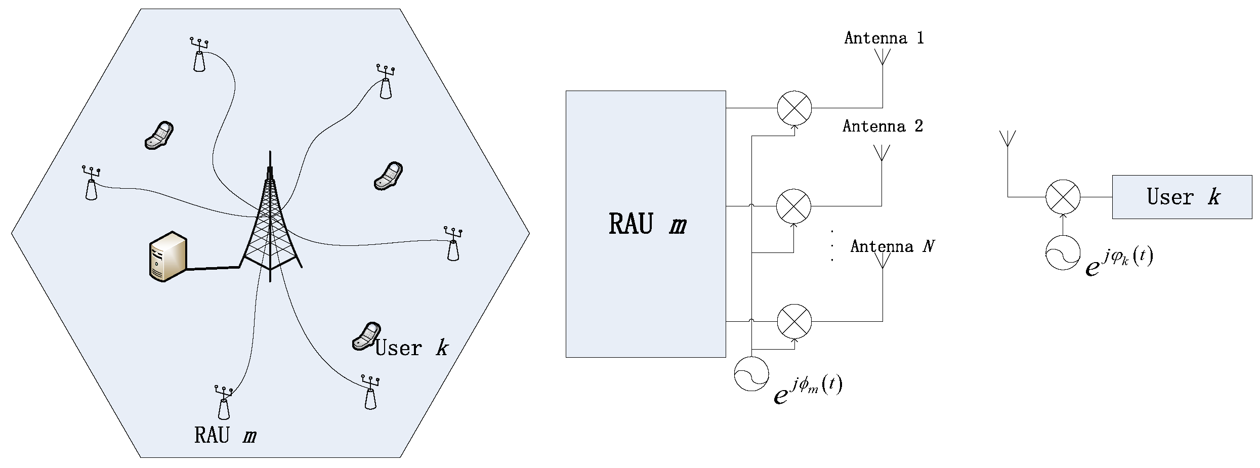
We consider the downlink transmission of a single-cell multi-user distributed massive MIMO system comprising
M RAUs and
K single-antenna users as in
Figure 1. Each RAU is equipped with an array of
N antennas. All users and RAUs are randomly distributed in the cell.
Frequency-flat fading channels are assumed and the system runs in time-division duplex (TDD) protocol. The channel vector between all RAUs and the
k-th user is given by
where
is the covariance matrix,
denotes the path loss between the
m-th RAU and the
k-th user,
is the corresponding distance,
is the path loss exponent,
c is the median of the mean path gain at a reference distance
km, and
is the small-scale fast fading vector.
In this paper, we consider a more realistic scenario where the antennas deployed at each RAU are inexpensive and hardware-constrained. Specifically, each antenna experiences phase noise which distorts communication. The phase noise means the multiplicative phase drift in the signal, which comes from the local oscillators (LOs) of the RAUs and users. We assume that the LOs are free-running without a phase-locked loop (PLL), and then the phase noise is commonly modeled as a discrete-time independent Wiener process [
8,
25]. Mathematically, the phase noises at the LOs of the
n-th antenna and the
k-th user are denoted as
which equal the previous realization
and
plus an independent zero-mean Gaussian random increment with variances
and
. The variances are dependent on the carrier frequency and symbol time [
25].
The phase noise can be independent or correlated between antennas of each RAU. In our analysis, we have assumed that the phase noise correlated between antennas of one RAU and independent among RAUs. Then by expressing the total phase noise as a multiplicative factor, we can rewrite the channel vector as
where
is the total phase noise, wherein
is the phase noise induced by all RAUs, and similarly,
corresponds to the phase drift pruduced by the
k-th user. Notably, because of the presence of phase noise, the effective channel becomes time-dependent.
Remark 1. The conventional channel model without phase noise is obtained when .
3. Downlink Spectral Efficiency Analysis
In this section, firstly, based on the effective channel model given above, we assume pilot sequence aided transmission is employed and give the channel estimation. Next, since the channel vectors are non-isotropic in distributed massive MIMO and the correlation between channel vectors and intended beams for each user is destroyed by phase noise, we give the approximated distribution of desired signal and interference powers. After that, we derive the closed-form expressions of the ergodic achievable downlink rates with both MRT and ZF precoders.
3.1. Channel Estimation
As mentioned before, the transmission protocol is assumed as TDD. Each coherence block occupying T channel uses is split into two parts: one for uplink pilot symbols and the other for downlink data symbols. In order to guarantee that the pilot symbols of K users are orthogonal to each other, it’s necessary to allocate symbols for pilot transmission. Then the remaining channel uses are used for downlink data transmission.
During the pilot training phase, the pilot sequence
is assigned to user
k. Incorporating the hardware impairments, the received pilot vector
at the base station at time
is given as
where
is the amplified thermal noise at time slot
t, and its variance
is larger than the variance
of thermal noise. This is because of the effects of low noise amplifiers, mixers and other components.
Let
. Motivated by [
8,
26], the Linear Minimum Mean Square Error (LMMSE) estimation of the channel of the
k-th user obtained by pilot training is given by
where
The pilot sequences can be designed in different ways. Without loss of generation, in this paper we assume that the number of pilot symbols is equal to that of users, i.e.,
. More specifically, we assume that the set of orthogonal pilot sequences
is a diagonal matrix and each element of it is
, wherein
is the average transmit power of pilot symbols. This is equivalent to the assumption made in [
18,
20].
Under these assumptions, we give a definition of
then we can rewrite the LMMSE estimation
in (
6) as
where
is the equivalent large-scale fading part from user
k to RAU
m and
represents the equivalent small-scale fast fading part.
Because of the orthogonality principle of LMMSE estimation theory, the channel vector
can be decomposed as
where
is the uncorrelated and statistically independent of
estimation error.
During the pilot transmission phase, we obtain the estimated channel showing in (
8). In our analysis, it is assumed that the beamforming vector is designed by using the estimated CSI once during the pilot transmission phase and then is applied for the entire duration of the downlink transmission phase.
3.2. Downlink Signal Model
For downlink transmission, the received signal of user
k at time
is given as
where
is the downlink transmission power,
is the amplified thermal noise of users at time slot
t,
is the variance of the noise, and
is the signal vector transmitted by all
M RAUs. Specifically,
can be given by
where
is the transmitted data symbol assigned for user
l, and
is the beamforming vector designed at time slot
. MRT and ZF precoders are considered in our analysis. Mathematically, these two linear precoders can be defined as
where
is the
l-th column of
, wherein
. Considering (
4), we can rewrite (
10) as
where
It is assumed that users have the statistical properties of the channel and they don’t carry out channel estimation. So only statical CSI can be used by downlink users to detect the signal. Motivated by [
27], we rewrite the received data as
where
Suppose
is the only signal needed at user
k, and treating
as unrelated Gaussian distributed additive noise [
28,
29], the achievable downlink rate of user
k is denoted as
where
3.3. Downlink Achievable Rates
From (
16) we can find that the correlation between
and
are destroyed by phase noise and the powers of non-isotropic channel vectors projected onto the precoder subspace are necessary to obtain the closed-form expressions. Hence we first present some preliminary lemmas which help us to obtain the approximated and isotropic results.
Lemma 1 ([
28])
. For an isotropic random vector whose elements are independent and all distributed as , then the distribution of is . The strength of the estimated channel from user
k to all RAUs is
According to Lemma 1,
is distributed as
. Hence (
17) is the sum of
M non-identically distributed but independent items. To obtain its distribution, Lemma 2 stated bellow can be used.
Lemma 2 ([
15])
. If are a set of random variables and independent of each other, each term is distributed as . Then the distribution of the sum can be approximated as wherein Remark 2. From Lemma 2, the distribution of can be approximated as , wherein Similarly, we can also give the distribution of
as
, wherein
where
.
Based on the lemmas and analysis above, we give the following lemma about the projection principle of non-isotropic vectors.
Lemma 3 ([
28])
. When we project an -dimensional non-isotropic estimated channel vector onto a p-dimensional subspace, we can give the approximated distribution of the projection power as . Remark 3. The dimension p can be given by with MRT precoder and with ZF precoder, respectively, and for any independent beam, we can have [30,31]. When MRT and ZF precoders are employed, based on the analysis above, we can give the distribution of the signal power at user
k and the distribution of the interference power at user
kNotably,
in (
25) can be either MRT precoder or ZF precoder and the equation still holds when
, due to the independence of
and
.
Based on the analysis above, we can give the approximated distribution of
as
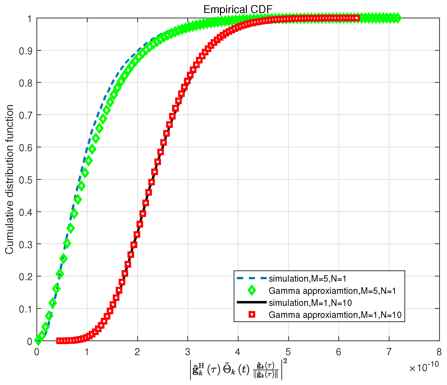
Figure 2 verifies the accuracy of the approximation in (
26) and (
27). It illustrates the cumulative distribution function (CDF) curves of
with MRT precoder. The phase noise variance is set as
. It can be seen that although the random variable
will destroy the correlation of
and
, the approximation is exactly accurate when the variance of the phase noise is
, and it will be more accurate when the variance of the phase noise is lower
. For ZF precoder, we can get the same conclusion. Meanwhile, the phase noise variance is generally
[
8,
20,
26]. Hence, it’s reasonable to use (
26) and (
27) to analyze the downlink spectral efficiency.
Based on the lemmas above, the spectral efficiency for downlink transmission with both MRT and ZF precoders under hardware impairments is analyzed. The theorems and corollary stated below give the closed-form expressions of the downlink achievable rates and system asymptotic performance.
Theorem 1. When MRT precoder is used, the closed-form expression of the downlink achievable rate under hardware impairments is given bywhere Theorem 2. When ZF precoder is used, the closed-form expression of the downlink achievable rate under hardware impairments is given bywhere Then, in order to study the effects of phase noise further, we investigate a case where the number of antennas employed at each RAU goes infinity and the number of RAUs and users is fixed. The asymptotic performance provided in Corollary 1 is obtained based on (
28) and (
29).
Corollary 1. Let , the ultimate rate of user k with both MRT and ZF precoders is given by Proof Since the proof is similar for both precoders, we only provide the proof for MRT precoder. It can be seen that
when the number of antennas
. Therefore we can have
[
29]. Then the limiting rate of user
k can be obtained directly by dividing the denominator and numerator of (
28) by
N. From Corollary 1 we can see that the ultimate rate without phase noise will be unlimited when
N tends to infinity, which means that phase noise limits the downlink spectral efficiency. □
4. Numerical Results
In this section, a series of Monte Carlo simulations is used to verify the theoretical results obtained in
Section 3. A circular single-cell massive MIMO system is considered. All of the RAUs and users are randomly distributed in the cell and the minimum access distance between RAUs and users is set as
m. The channels are generated by (
4), and other simulation parameters are presented in
Table 1.
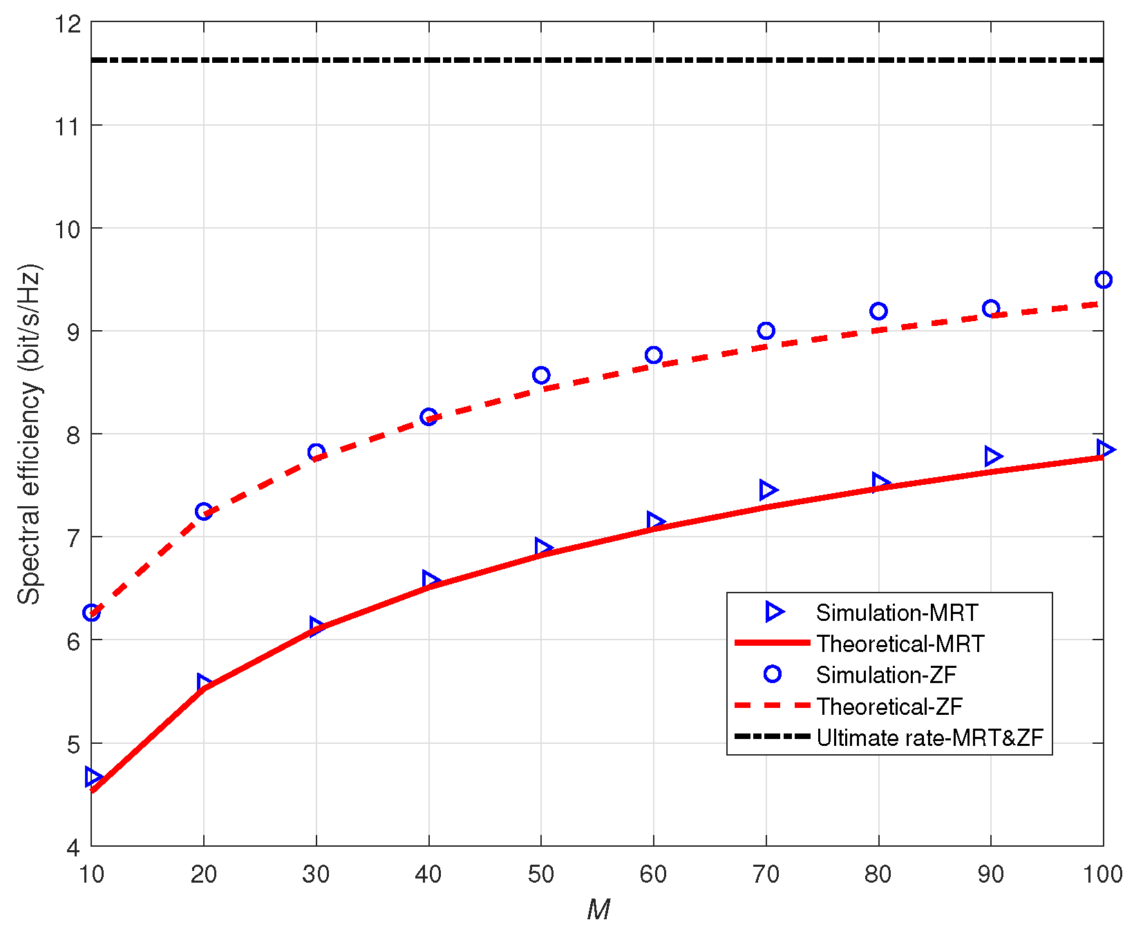
Figure 3 illustrates the theoretical and simulated spectral efficiency with MRT and ZF precoders versus the number of antennas per RAU. The spectral efficiency is the average rate between users. We assume that the variances of phase noise and amplified thermal noise are
and
.
t is set as
. It can be seen that the closed-form expressions in (
28), (
29) and the simulation results in (
16) match well with each other. For both precoders, the spectral efficiency increases and gets more and more close to the limiting average rate with the increasing of
N. When
, the system achieves
of the ultimate rate with ZF precoder and
with MRT precoder. Furthermore, it can be seen that ZF precoder achieves better performance than MRT.
Next, we investigate the effects of phase noise.
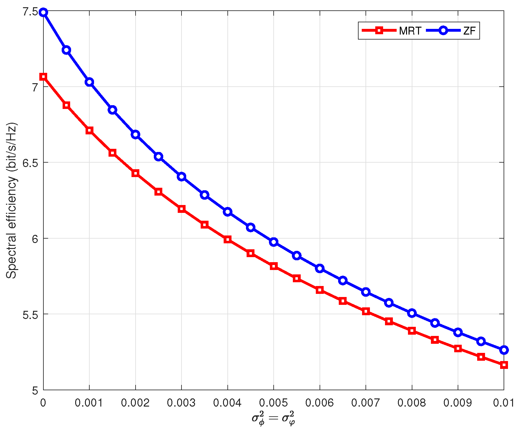
Figure 4 illustrates the theoretical spectral efficiency with MRT and ZF precoders against the variance of phase noise. Notably, the variance of phase noise reflects the strength of phase noise. It is assumed that the number of antennas
and other system parameters have the same value as
Figure 3.
Figure 4 reveals that the spectral efficiency decreases monotonically with the variance of phase noise increasing. In addition, phase noise have a greater impact on ZF precoder. This results form the fact that ZF precoder is more sensitive to CSI. It can be noted that as the variance increases, the performance gap between MRT and ZF precoders becomes smaller. This is because when the phase noise is severe, the loss caused by unknown CSI at user side dominates rather than the interference between users.
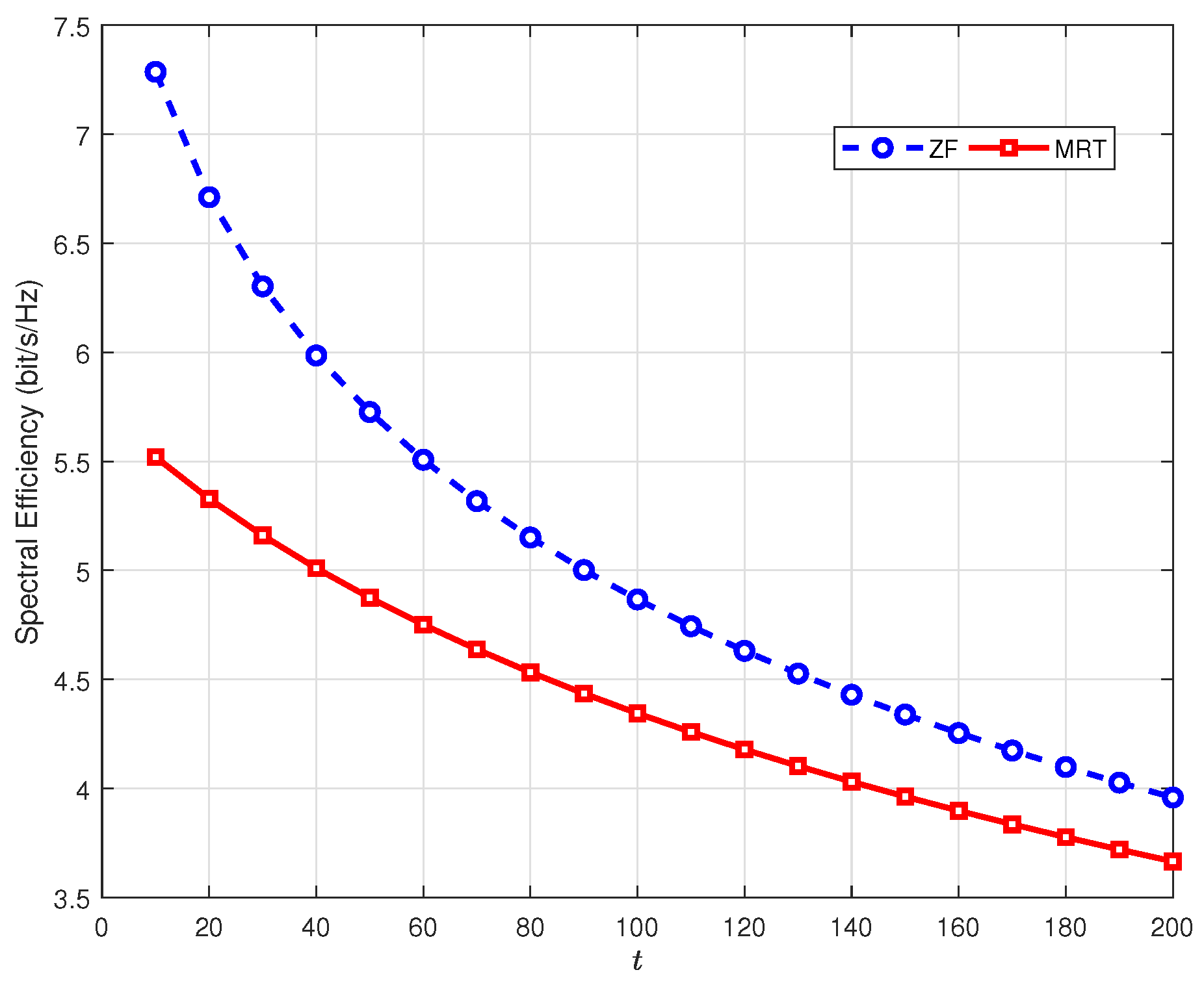
Figure 5 illustrates the instantaneous spectral efficiency during the downlink transmission phase. The number of antennas employed at each RAU is assumed as
and the variance of phase noise is set as
. In addition, the coherence time of channel is set as
. As shown in
Figure 5, the spectral efficiency degrades as
t increases. This is because the uncertainty of the phase drift between downlink transmission phase and pilot training phase increases with the growing of
t.
Figure 5 reveals that it’s improper to use the estimated CSI obtained during the pilot phase for the whole data transmission phase.
5. Conclusions
In this paper, we analyzed downlink spectral efficiency with hardware impairments in distributed massive MIMO. Initially, employing pilot symbol assisted transmission, we obtained the estimated CSI in a more realistic scenario where transmission is distorted by phase noise and amplified thermal noise. Next, we used the imperfect CSI to derive the closed-form expressions for downlink achievable rates with MRT and ZF precoders. In addition, we obtained the ultimate rate when . It can be seen that the rate performance was limited by phase noise. Then, numerical results proved that the theoretical analysis was accurate. Furthermore, they also revealed that ZF can achieve larger spectral efficiency than MRT precoder, and hardware impairments had a greater impact on ZF precoder. Finally, spectral efficiency degraded with the increasing of the variance of phase noise and downlink transmission time.
In the future work, we intend to extend our research considering a more effective phase noise model which could lead finer precoding strategies to improve the theoretical rates.
