Article

Decentralized Load Shedding Method Based on Voltage Stability Margin Index Using Synchrophasor Measurement Technology

Department of Electrical and Information Engineering, Seoul National University of Science and Technology, Seoul 01811, Korea
*
Author to whom correspondence should be addressed.
Electronics 2018, 7(11), 277; https://doi.org/10.3390/electronics7110277
Submission received: 20 September 2018 / Revised: 19 October 2018 / Accepted: 23 October 2018 / Published: 26 October 2018
(This article belongs to the Section Power Electronics)

Abstract

:
This study develops an analytical method for assessing the voltage stability margins of a decentralized load shedding scheme; it then examines the challenges related to the existing load shedding scheme. It also presents a practical application for implementing the proposed method, based on the synchrophasor measurement technology in modern power grid operations. By applying the concept of a continuously-computed voltage stability margin index to the configuration of the Thévenin equivalent system, the maximum transfer power could be used as an index to monitor the voltage instability phenomenon and thus determine the required load shedding amount. Thus, the calculated voltage stability margin might be a useful index for system operators in the critical decision-making process of load shedding. Dynamic simulations are performed on real Korean power systems as case studies. Simulation results, when comparing the existing and proposed methods, showed that there was a considerable reduction in the amount of load shedding in the voltage instability scenario. This indicates that the synchrophasor measurement technology has a considerable effect on the proposed load shedding method. The simulation results have validated the performance of the proposed method.

1. Introduction

Nowadays, the heavy loading of transmission and distribution networks has made power systems operate close to their stability limits, resulting in a higher risk of voltage instability. Under these conditions, security and reliability might be seriously compromised since unexpected disturbances cause the degradation of the voltage stability. Therefore, adequate countermeasures should be taken to stabilize the power system [1,2,3,4]. Some of the most important available countermeasures that have been applied are under voltage load shedding (UVLS), shunt capacitor switching, flexible AC transmission systems to extend the voltage stability margin and tap changer blocking, where UVLS is the last line of defense [5]. Thus, the UVLS method could be considered an effective countermeasure in situations when voltage instability is anticipated. The conventional UVLS scheme is executed in the case of a violation of voltage stability criteria. A UVLS scheme is used in conditions where the voltage magnitude becomes lower than a predefined value [6,7,8,9,10,11].
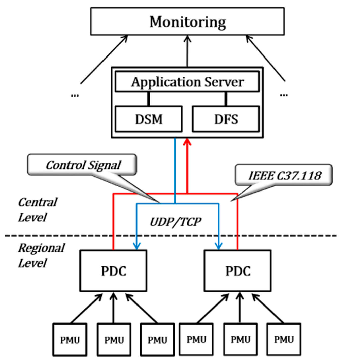
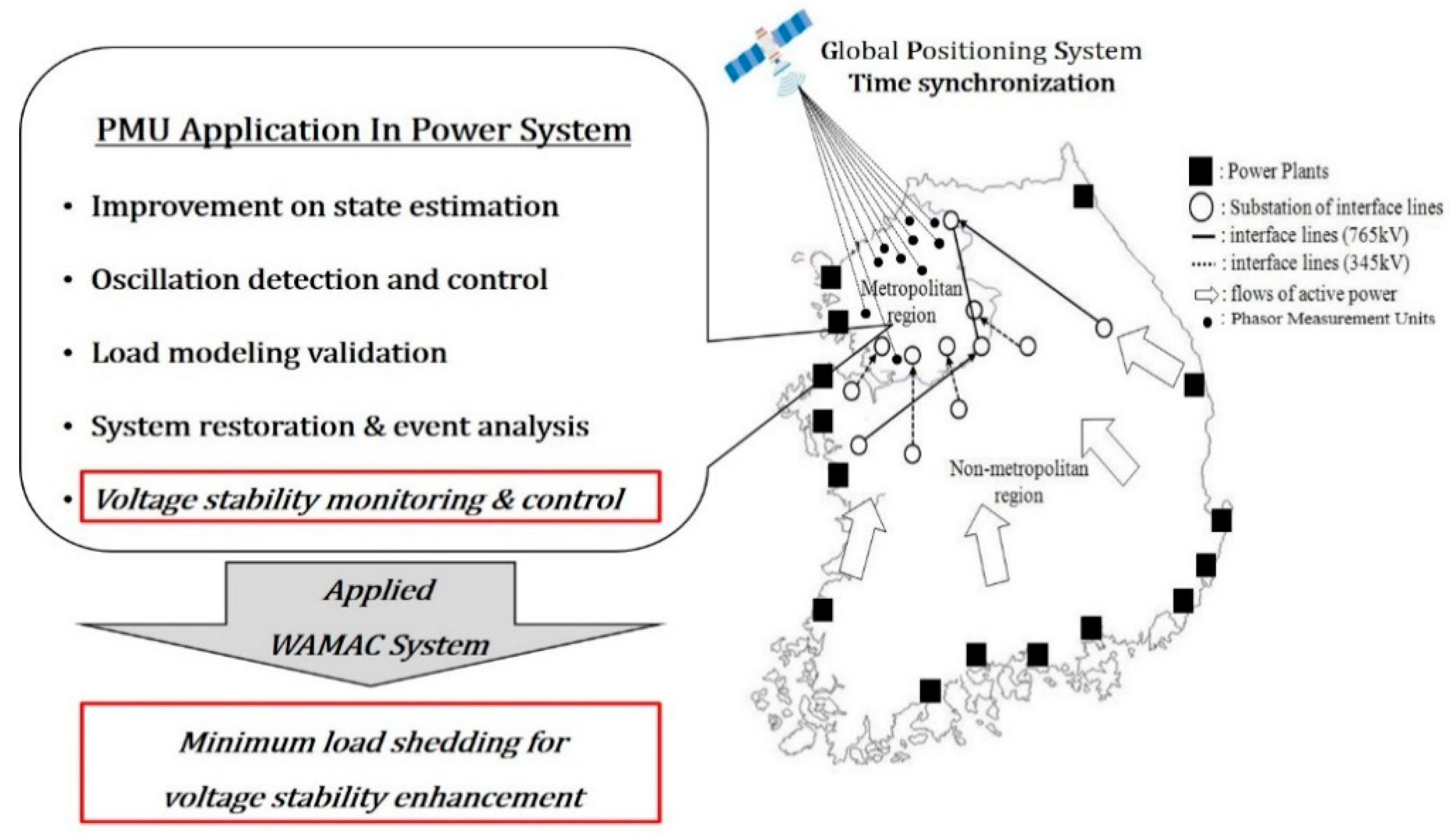
In the Republic of Korea, a wide area monitoring and control (WAMAC) system has been developed and is operational; phasor measurement units (PMUs) were installed in major substations in the metropolitan area for providing real-time power system information to the operators [12]. The method of load shedding in current WAMAC systems is designed based on centralized management schemes. Furthermore, the applied special protection scheme (SPS) of the Korean power system has been designed to operate during contingencies involving an outage in one route of a 765 kV double circuit line in the load concentrated area. The SPS is operated at each end of the transmission line by a protective relay. The contingency signal detected by the protective relay is transmitted to a supervisory control and data acquisition/energy management system (SCADA/EMS) system. However, the SCADA/EMS system cannot respond to contingencies in real time and is not able to take the role of an efficient monitoring system. This scheme uses a fixed voltage threshold, fixed time delays and a fixed amount to shed the loads, resulting in the possibility of excessive load shedding. Additionally, this method does not include real-time system conditions and other important information and lacks the flexibility to execute load shedding control schemes fit for the different types of instability [13,14,15].
Several schemes have been developed in previous studies to overcome the limitations of the conventional UVLS scheme. To improve the precision and efficiency of load shedding practices, some studies have developed wide area monitoring mechanisms. These approaches make use of the synchrophasor measurement technology (SMT) attained based on PMUs [16,17,18,19,20,21,22,23,24]. PMUs could provide synchronized measurements, which include the magnitude and phase angles of voltages and currents. These measured data might support the tracking of dynamic phenomena and provide sufficient information for voltage stability assessments. Moreover, PMUs have been proven to facilitate a more accurate and early voltage instability detection [25,26,27,28]. Nevertheless, they have seldom been applied in existing load shedding methods. Utilizing the PMU applications based on SMT in WAMAC systems might significantly improve the performance of power system monitoring and control over existing schemes [29,30,31,32,33,34]. Additionally, frequency control is one of the important problems in system operation, and for that purpose, load shedding can be also used. The allocation of available electricity power among candidate shed loads has been taken as a bankruptcy problem, and a multi-agent system has been used, as in [35]. In [36], a new load shedding scheme based on the bankruptcy problem was proposed using non-critical loads in grid disconnected mode. Installing the PMUs and getting to know the WAMAC systems’ behaviors through the continuous observations of power system events has been the first step. Monitoring, protection and control applications can be developed based on the measurement information obtained from substations. The next step is to pursue the stabilization of the grid by performing an appropriate application when voltage instability occurs in the power system.
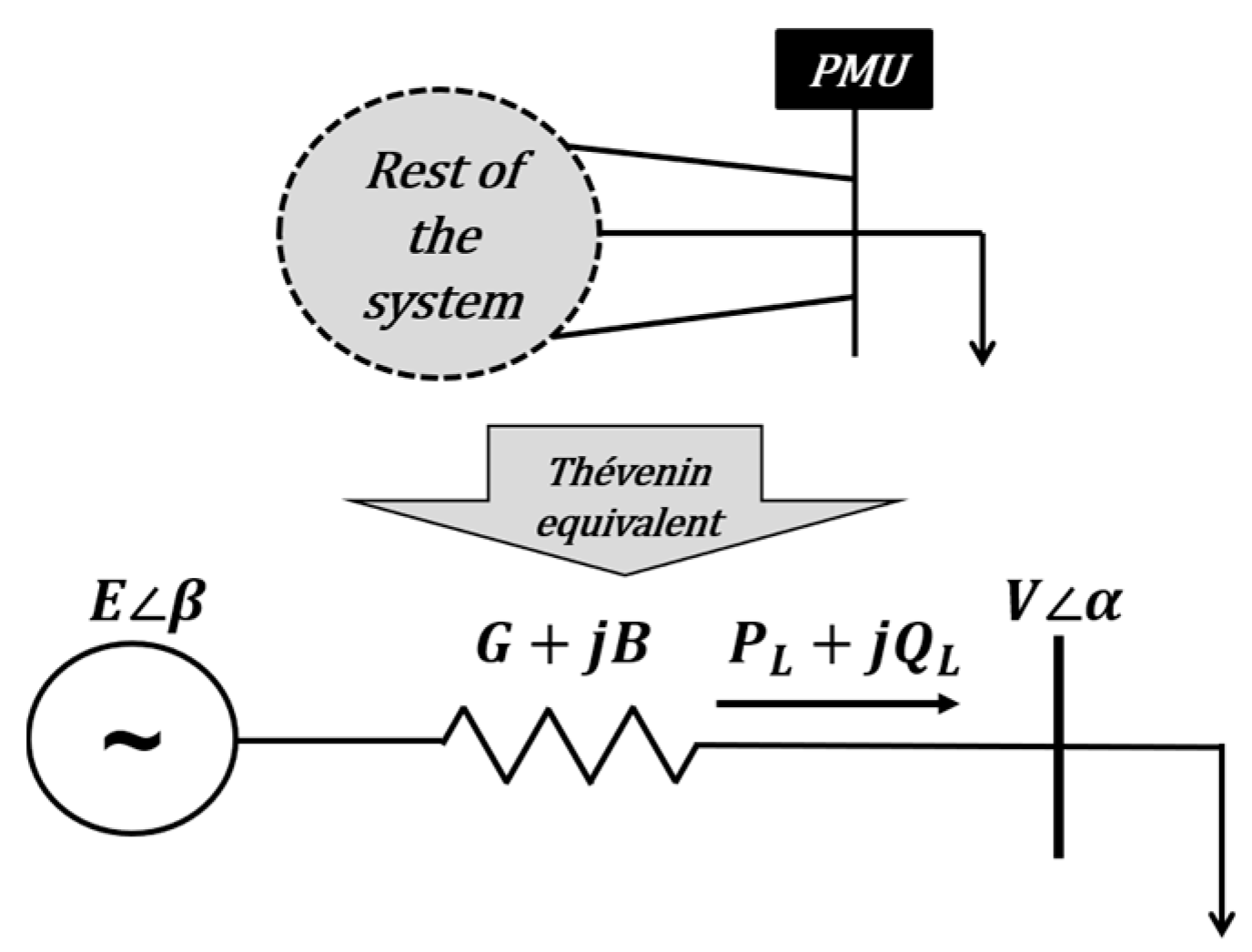
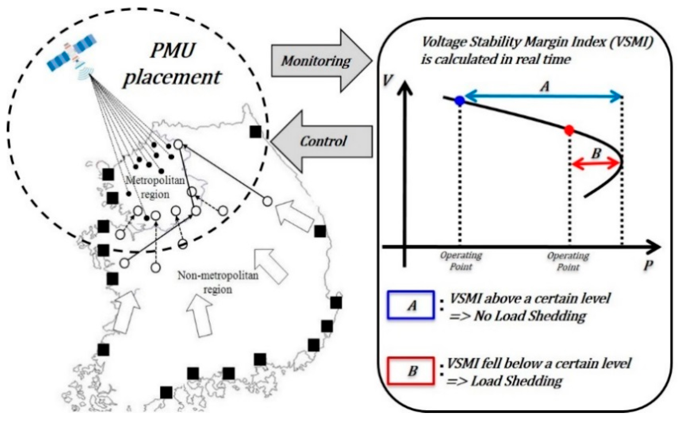
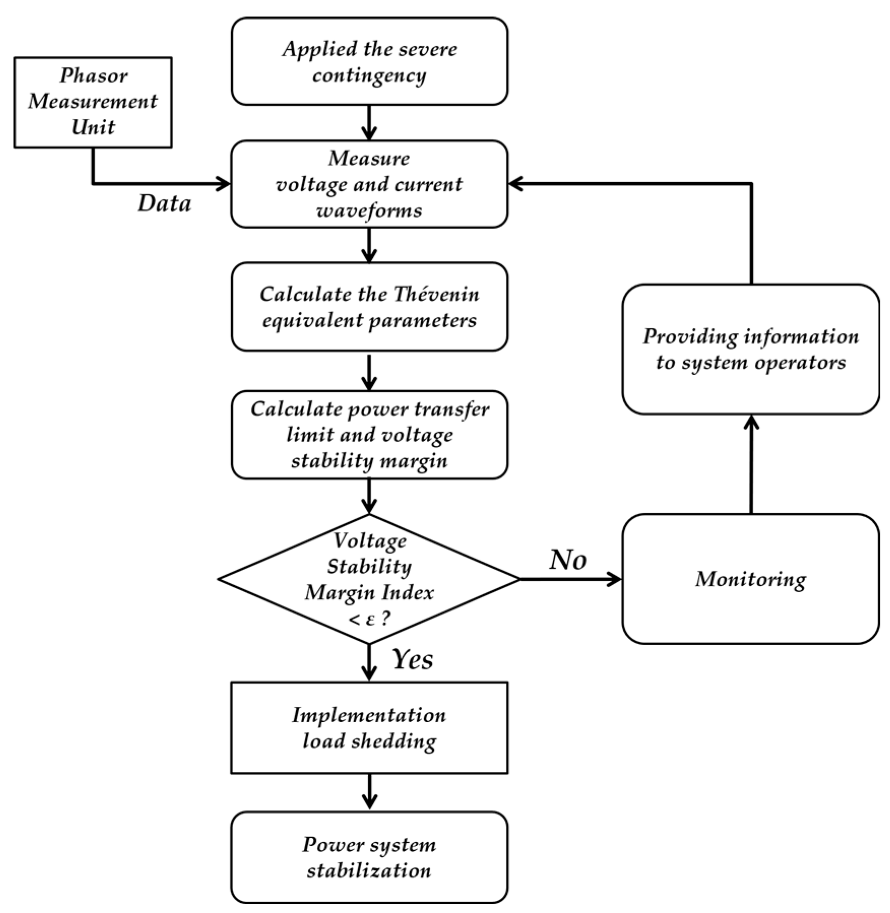
For this purpose, this paper proposes a new control load shedding scheme, which aims to enhance the existing load shedding scheme. The decentralized load shedding scheme could control the load at the substation by using the measured data. SMT was used to enable more advanced load shedding based on the voltage stability margin index (VSMI). In addition, the voltage stability margin, a key component in determining the optimal amount of load shedding, was calculated in real time. The maximum power transfer value calculation for determining the real-time voltage stability was performed based on the voltage and current data acquired from the PMU. The method estimates Thévenin equivalent system impedance, then calculates the VSMI and compares the VSMI with the pre-set threshold to decide whether to activate a load shedding action. The optimal amount of load shedding is determined with the help of a threshold value that has to be estimated online using the VSMI. The proposed method can reduce the amount of load shedding by selecting the proper location and shedding an adequate amount for selected locations within seconds after the critical fault. Thus, the method adopts an adaptive and contingency independent scheme, and it provides the results of the applied shedding with maximum transferable active and reactive power at those buses experiencing the shedding action. Other features of the proposed method are as follows: (i) the proposed method can consider the dynamic behavior of the power system based on the obtained PMU data; (ii) the proposed method can provide a fast enough response to prevent short-term voltage instability; and (iii) the computational burden of the proposed method does not change significantly even if it increases the load capacity of the power system. Case studies on the Korean power system have validated the performance of the proposed decentralized load shedding scheme, showing that it effectively reduced the amount of load shedding under contingency scenarios involving the severe failure of high-voltage transmission lines.
The structure of this paper is organized as follows. The role of the synchrophasor measurement technology for implementing the proposed load shedding method and the application of the phasor measurement unit for obtaining the information required in improved wide area monitoring and control of the power system are described in Section 2. It also includes the fundamental theories and mathematical principles of the proposed load shedding scheme based on the voltage stability margin index. Section 3 presents the simulation results and discussions on the verification of the performance of the proposed scheme using a practical system. Finally, Section 4 includes the conclusions and future research directions.

2. Materials and Methods

2.1. Synchrophasor Measurement Technology

The synchrophasor is defined as a complex number representation of either a voltage or a current, at the fundamental frequency, using a standard time reference in the IEEE standard C37.118. Furthermore, this standard defined data transmission formats for real-time data reporting [37]. The synchrophasor representation X of a sinusoidal signal x ( t ) is the complex value expressed as:
  X = X r + j X i = ( X m 2 ) e j ϕ = X m 2 ( cos ϕ + jsin ϕ )  
where X m 2 is the root mean squared value of the sinusoidal signal x ( t ) and ϕ is its instantaneous phase angle relative to a cosine function at nominal system frequency synchronized to Universal Time Coordinated (UTC). The synchronizing signal had to have an uninterrupted and continuous availability, and it had to offer easy access to every place where the electric variables were measured [21,38]. SMT has become one of the most important technologies in power systems. An SMT provides the dynamic state of the power grid along with information such as the bus voltages and currents, as well as the generator and transformer flows. PMUs are the most commonly-used devices for synchronized phasor measurements. The information obtained from a PMU is synchronized by the global positioning system (GPS); therefore, all the data have the same time tags. This allows the direct measurement of voltages and phase angles and shows what is happening on the grid in real-time for the power system operators. Therefore, the effective monitoring and control of a wide area power system in real time is possible with SMT [39,40,41,42]. The configuration of the PMU implementation architecture based on SMT is represented by the PMU, the phasor data concentrator (PDC), a fast communication network, a data gathering system and a central system that displays the power system information. A PMU can measure basic time data synchronized with phasor information. Moreover, it is equipped with a communications channel, which can send the measured phasor data. The configuration of the PMU implementation architecture based on SMT is shown in Figure 1.
From Figure 1, one can notice that the synchrophasor data are collected from the PMUs and transmitted to the PDCs, and the data are then transmitted to the distributed shared memory (DSM) of the center. The DSM is a system that caches, distributes and stores transmitted data. The data transmitted to the DSM are stored in a file basis through the distributed file system (DFS) to perform the search, analysis and failure recovery. The phasor measurements are grouped, and the data packets are transmitted to a central site from several measurement locations such as substations [43]. Based on the SMT, a wide area measurement system (WAMS), which gathers real-time phasor measurements taken by PMUs across broad geographical areas, has been gradually implemented. WAMS has been developed to ensure the reliability of the system’s operation, and simultaneously to be used as a foundation technology for the power system control schemes. WAMS is valuable for power system identification, power system monitoring, control center state estimation and power system dynamic performance analysis following disturbances. Since WAMS was developed, a WAMAC system has been developed to counter large disturbances that cause voltage collapse and voltage instability. A WAMAC system is a concept that combines a wide area control system (WACS) with WAMS. WACS is a control technology used for maintaining the system operating point and preventing voltage instability based on synchronized real-time system information (WAMS) [40,41]. In order to advance the reliability and availability of WAMAC, a PMU application strategy needs to be developed.

2.2. PMU Application of the WAMAC System

The development of the WAMAC system has prepared the basis for improving the stability and reliability of the power system by establishing an environment that might acquire the important information necessary for its stable operation in real time. The WAMAC system could analyze the situation of the power system by using the real-time information measured by the PMU installed at the substation/power plant and might precisely comprehend the voltage and power flow in the main (metropolitan) area. The high-precision power data acquired by the PMU could be measured 60 times per second, and at the same time, the power data might be time-synchronized in steps of one micro-second using a GPS satellite. This improves the wide area situational awareness and can be effectively used to analyze the dynamic statement fluctuation of the power system. The WAMAC system is a platform that might use synchrophasor measurements gathered from a wide area for monitoring and control. The WAMAC has several functions and effects, namely: on-line power system operation; analysis of the power system and calculation of the stability index in real-time; advanced SPS connected with the WAMAC system for real-time assessment and control; and minimization of load shedding throughout to stabilize the voltage of the metropolitan area [40,43]. Figure 2 shows the PMU application based on SMT in the WAMAC system.
From Figure 2, one can notice that the PMU application in the WAMAC system consists of the development of a voltage stabilization control system using PMU data to improve the existing load shedding system, optimum PMU placement and installation locations and the development of a voltage stability monitoring index. Table 1 shows the final goal of an improved load shedding scheme.
SMT has enabled PMU applications, and this is beneficial for stability assessments and load shedding. PMU applications provide an environment for implementing load shedding in WAMAC system platforms, thus facilitating the realization of load shedding. As mentioned above, the existing UVLS system considers the occurrence of a failure in the most serious situation based on the maximum load and sheds the entire predetermined load, so excessive load shedding might be performed depending on the situation. To overcome these problems, it is possible to apply a decentralized load shedding method that can accurately plan the stability of the system using the PMU to shed the optimum amount of load depending on the system conditions. The WAMAC project, which was carried out to improve the voltage stability of the Korea power system, installed 40 PMUs on 28 buses in the metropolitan area [12]. This can be used to implement the proposed load shedding method.

2.3. Decentralized Load Shedding Method

SMT has become available in WAMAC transmission systems. Based on these technologies, wide area voltage stability monitoring and control has become feasible, which could increase the power transfer limits and reliability of power system operations. The decentralized load shedding scheme could control the load at each substation using the synchronized data from the PMUs. This method measures the voltage stability or instability in each individual location. Furthermore, a real-time voltage stability margin could be provided for load shedding by the system operators. Load interruption could be implemented to avoid voltage instability, and coordination with other substations would be done continuously to monitor and maintain wide area voltage stability [38,44].
The decentralized load shedding method to determine the real-time voltage stability was performed based on the voltage and current data acquired from the PMU. The entire power system was composed of a Thévenin equivalent circuit used to calculate the real-time active ( P ) and reactive ( Q ) power margin. The configuration of the Thevenin equivalent circuit based on the information measured on the load bus can be expressed as shown in Figure 3.
From Figure 3, one can notice that the actual P   and Q   transferred from the system to the load are represented by:
  P L = E V Y cos ( α δ β ) V 2 G  
  Q L = E V Y sin ( α δ β ) + V 2 B  
where E is the magnitude and δ is the angle of Thévenin equivalent generator terminal voltage; V is the magnitude, and α is the angle of load bus voltage; Y is the magnitude, and β is the Thevenin equivalent admittance Y = G + j B . The above equation divided by E 2 Y can be expressed as:
  p = v cos ( α δ β ) v 2 cos β  
  q = v sin ( α δ β ) + v 2 sin β    
where:
p =   P L E 2 Y ,   q =   Q L E 2 Y ,   v =   V E  
Moving V 2 cos   β and V 2 sin   β to the left sides, taking the square of the right and left sides and adding, the following equation is obtained:
  ( p + v 2 cos β ) 2 + ( q v 2 s i n ) 2 =   v 2  
Substitute q with p   t a n   ϕ , where ϕ is the power factor of load. From Equation (7) is obtained:
  p = v 2 cos ϕ cos ( ϕ + β ) +   cos ϕ v 2 v 4 s i n 2 ( ϕ + β )  
Taking the derivative and setting it equal to zero, the above equation can be derived from v as follows:
  p v = 1 4 v 2 + 4 v 4 s i n 2 ( ϕ + β ) = 0  
In the above equation, V c r i t i c a l and the maximum P   and Q values can be obtained. V c r i t i c a l can be calculated using the measured power factor and estimated Thévenin parameters ( E and β ). P   and Q reach their maximum values P m a x and Q m a x , which are the real and reactive power transfer limits, respectively, and can be calculated by:
  V 2 c r i t i c a l = 1 c o s ( ϕ + β ) 2   s i n 2 ( ϕ + β ) = 1 2 [ 1 + c o s ( ϕ + β ) ]  
  P m a x = c o s ϕ 2 [ 1 + c o s ( ϕ + β ) ]  
  Q m a x = sin ϕ 2 [ 1 + c o s ( ϕ + β ) ]  
The critical voltage and maximum power transfer value can be used as an index to monitor the voltage instability phenomenon. From Equations (4) and (5), by transforming them to include the original variables, the values are obtained from the following equation:
  V c r i t i c a l = E V c r i t i c a l = E 1 2 [ 1 + c o s ( ϕ + β ) ]  
  P m a x = E 2 Y p m a x = E 2 Y c o s ϕ 2 [ 1 + c o s ( ϕ + β ) ]  
  Q m a x = E 2 Y q m a x = E 2 Y sin ϕ 2 [ 1 + c o s ( ϕ + β ) ]  
The voltage stability margins, in terms of the real and reactive power transfers, are denoted by P m a r g i n and Q m a r g i n , which indicate the available power transfer capabilities without causing voltage instability. Using the maximum power transfer values, the voltage stability margin index (VSMI) is determined. The VSMI is expressed in terms of active, reactive and apparent power and indicates how much load should be shed to prevent voltage instability in the power system.
  P m a r g i n = P m a x P L  
  Q m a r g i n = Q m a x Q L  
  S m a r g i n = P 2 m a x   +   Q 2 m a x P L  
The decentralized load shedding scheme continuously computed the VSMI to track the voltage stability margin at the individual load bus level. When the voltage stability conditions were below a threshold, it would send an alarm signal to inform system operators and perform load shedding. The concept of the decentralized load shedding method can be expressed as shown in Figure 4.
From Figure 4, one can notice that the maximum power transfer and the P   and Q values from each load bus determine the value of the voltage stability margin. When the VSMI fell below a certain level, load shedding was implemented at each load bus. The decentralized load shedding method used the data from each load bus in the PMU, which was obtained by the real-time monitoring system. Furthermore, the voltage stability margin was calculated in real time for optimal load shedding control. Figure 5 shows the flowchart representation of the algorithm for the method proposed in this paper.

3. Results and Discussion

In this section, the validity of the proposed method is demonstrated for a practical system; the simulations were conducted using real Korean power systems data. The Korean power system is peculiar in that the load demand is concentrated in and around the metropolitan region. The major generators are mostly located in the non-metropolitan region, and it is for this reason that a large amount of active power flows through a set of interface lines connecting them to the metropolitan region. Among these, the 765 kV transmission lines are the critical interface lines for transferring power from the large generation plants to the metropolitan region. When a fault occurs in the parallel 765 kV lines, unless immediate countermeasures are applied, this leads to the voltage instability phenomenon. Figure 6 shows the observed bus voltage profile without load shedding.
From Figure 6, the contingency scenario along with the time domain are summarized as: a fault occurred in the 765 kV line at 2.0 s; after five cycles, the shunt reactor was disconnected and the fault was cleared; five of the eight generators were tripped at 2.15 s, respectively. The generator and transmission lines played a significant role in the power system, based on the large respective generation and transmission capacity in the steady-state condition before the disturbance occurred [45]. Therefore, their contingencies led to an active power insufficiency accompanied by a reactive power insufficiency. Therefore, this disturbance caused the voltage instability phenomenon; no load shedding action was taken; eventually, all buses were beyond the threshold; and the system fell into a dangerous condition. Therefore, this transmission line fault signal would be transmitted to the metropolitan region’s control center. In the case of a transmission line trip or an under-voltage condition, the load shedding control signal would be transmitted to the metropolitan region considering the predetermined location, amount and delay time.
Typically, the load shedding scheme would be activated when a value lower than the predefined value is detected. The load shedding method must be able to increase the voltage of all buses above 90% of the pre-contingency voltage [46]. For the case study, the load shedding was performed by selecting 15 buses in the metropolitan region that exhibited the most sensitive changes in the event of a line fault, and the PMUs were installed at the load buses. In this paper, after the occurrence of a fault, the results obtained via the conventional method are compared to those obtained via the proposed load shedding method.

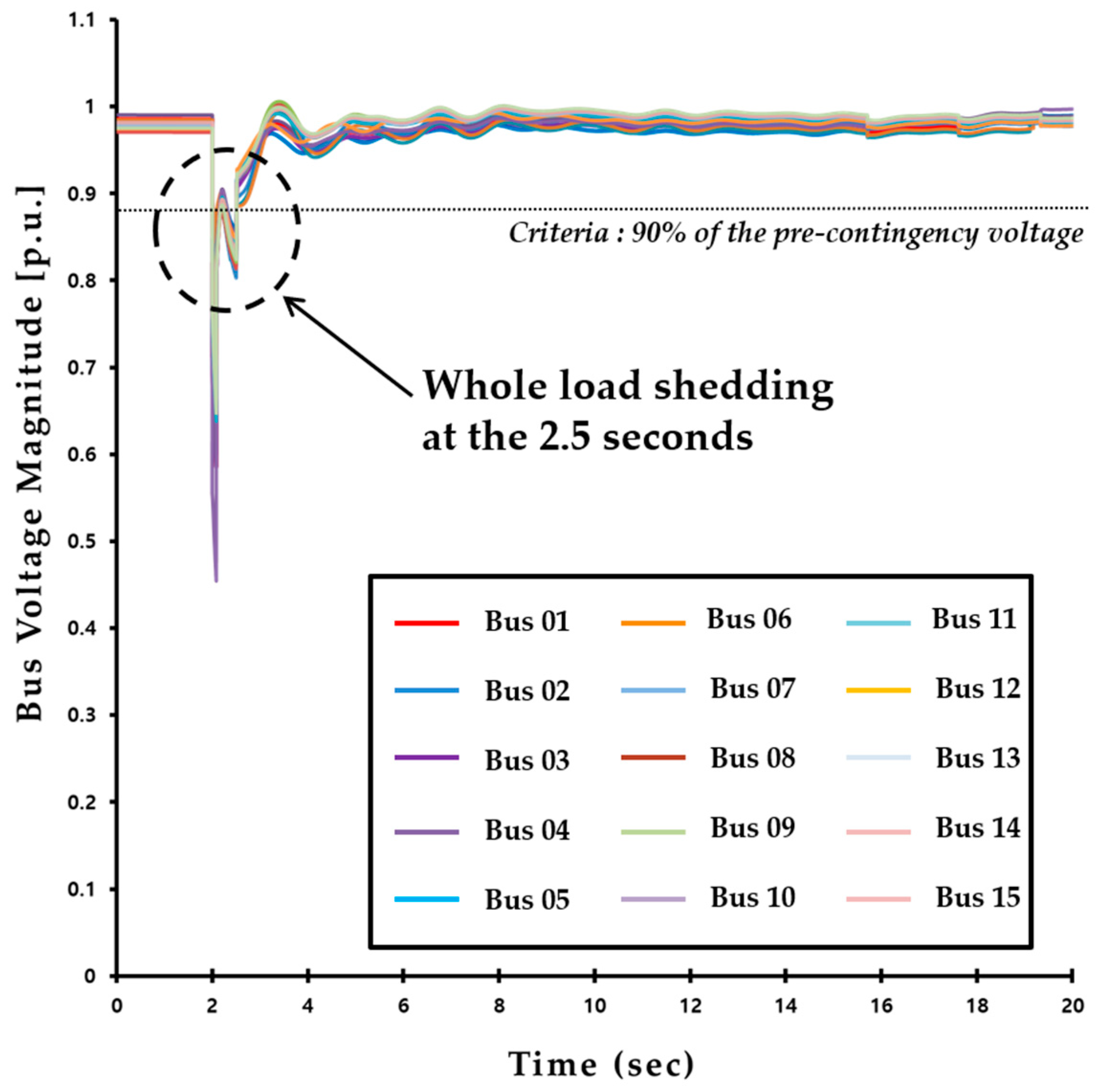
3.1. Existing Load Shedding Method

In the existing load shedding method of the Korean power system, the amount of load that is shed is decided based on the results of a steady-state analysis, and the dynamics of the power system are not considered. The decision making of the load shedding is usually provided by system operators, depending on pre-established practical criteria. In the existing scheme, any information on the sensitivity to the variations in voltage is transferred to the central controller, which decides whether to shed the load depending on the logic based on under-voltage relays, which send the signals to the actual load shedding areas. Then, the designated load in the metropolitan region is shed after the fault occurrence. Table 2 shows the descriptions of the implementation procedures of the time-domain simulation in the applied voltage instability scenario.
From Table 2, one can notice that the same voltage instability scenario was used until Step 3. In this case, a load shedding method was implemented at 2.5 s, and it shed the entire load at the same time. By shedding 100% of the load bus, control was performed to prevent voltage instability in the system. Then, the bus voltage was monitored at the end of simulation. Figure 7 shows the observations for the bus voltage profile with the existing load shedding method.
From Figure 7, one can notice that when applying the existing load shedding scheme, voltage instability was alleviated. Reviewing the voltage after load shedding, all bus voltages had recovered to above 90% of the pre-contingency voltage. In this case, Buses 1–15 implemented load shedding. The amount of load shedding was about 1270 MW. Table 3 summarizes the location, delay time and amount of the existing load shedding scheme.

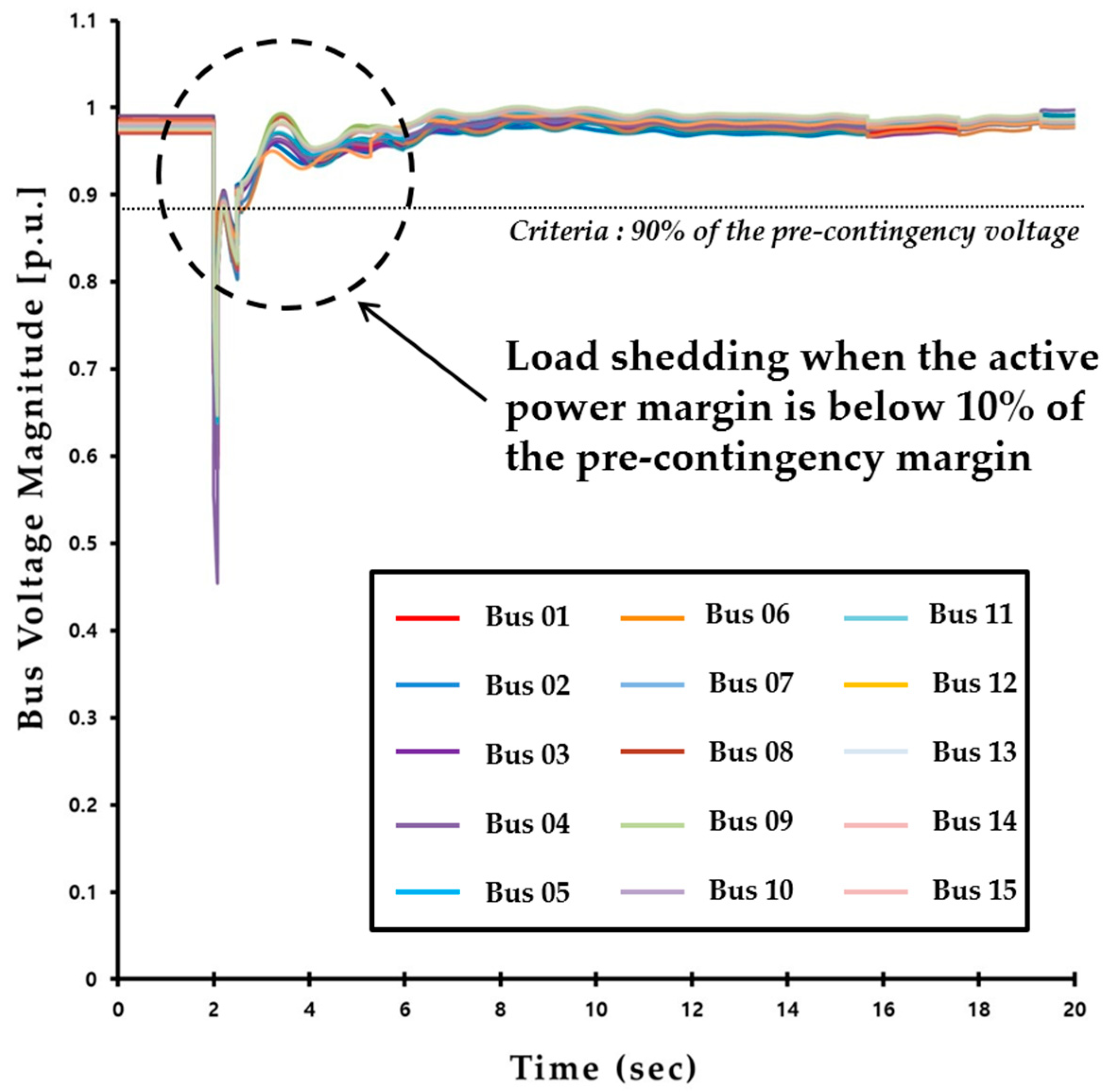
3.2. Proposed Load Shedding Method

In the decentralized scheme, the load could be controlled at the individual substation level using the data measured by the PMUs. This method was able to calculate the VMSI in real time at a local load bus by using the measured voltage and current waveforms. This could provide system operators with the power transfer limit for the load bus, not only in terms of active power, but also reactive power support required at that load bus. Furthermore, load shedding might be executed to prevent voltage instability, and coordination with other substations continuously performed to monitor and maintain control over wide area voltage stability. When this method detected that the voltage stability conditions violated an emergency level, it would perform the local load shedding function. Table 4 shows the descriptions of the implementation procedures of the time-domain simulation with the proposed method in the same voltage instability scenario.
From Table 4, one can notice that load shedding was implemented when the active power margin fell below a certain level. The active power margin was a key component in determining the optimal amount of load shedding, which was calculated in real time. Additionally, it provided information about how much load needed to be shed based on the PMU data. Figure 7 shows the variation results of the active power margin.
In the applied simulation for the proposed method, the disturbance occurred at 2 s. The active power margin of most buses dropped significantly, as shown in Figure 8. Therefore, depending on the line fault, the individual threshold values were exceeded, thus initiating the load shedding procedure. However, Buses 2, 3, 10 and 13 maintained a certain amount of active power margin after the fault’s occurrence. These buses did not implement load shedding because the active power margin did not drop below 10% of the pre-contingency margin after the occurrence of a fault. As a result, in this situation, applying the proposed method reduced the amount of load shedding. The results of the bus voltage profile for the proposed scheme are shown in Figure 9. Table 5 shows the results of the active power margin before and after the contingency.
From Figure 9, reviewing the voltage after load shedding, all bus voltages had recovered to above 90% of the pre-contingency voltage. In this case, Buses 1, 4, 5, 6, 7, 8, 9, 11, 12, 14 and 15 implemented load shedding. The amount of load shedding was about 1111 MW. Table 6 shows the load shedding bus location, delay time and amount of the load shed for the application of the proposed scheme.
This result indicates that the proposed method was effective in preventing system instability, and were are able to reach a steady state thanks to the load shedding actions. As is clear, the advantage of the proposed method is to reduce the amount of load shedding from that using the existing method. This would lead to less switching in the process of load shedding, and the maintenance cost benefit of the breakers would decrease. Additionally, if the system dynamics were monitored with more accurate measurements, it might be possible to counteract contingent incidents caused by transmission constraints on the system operation.

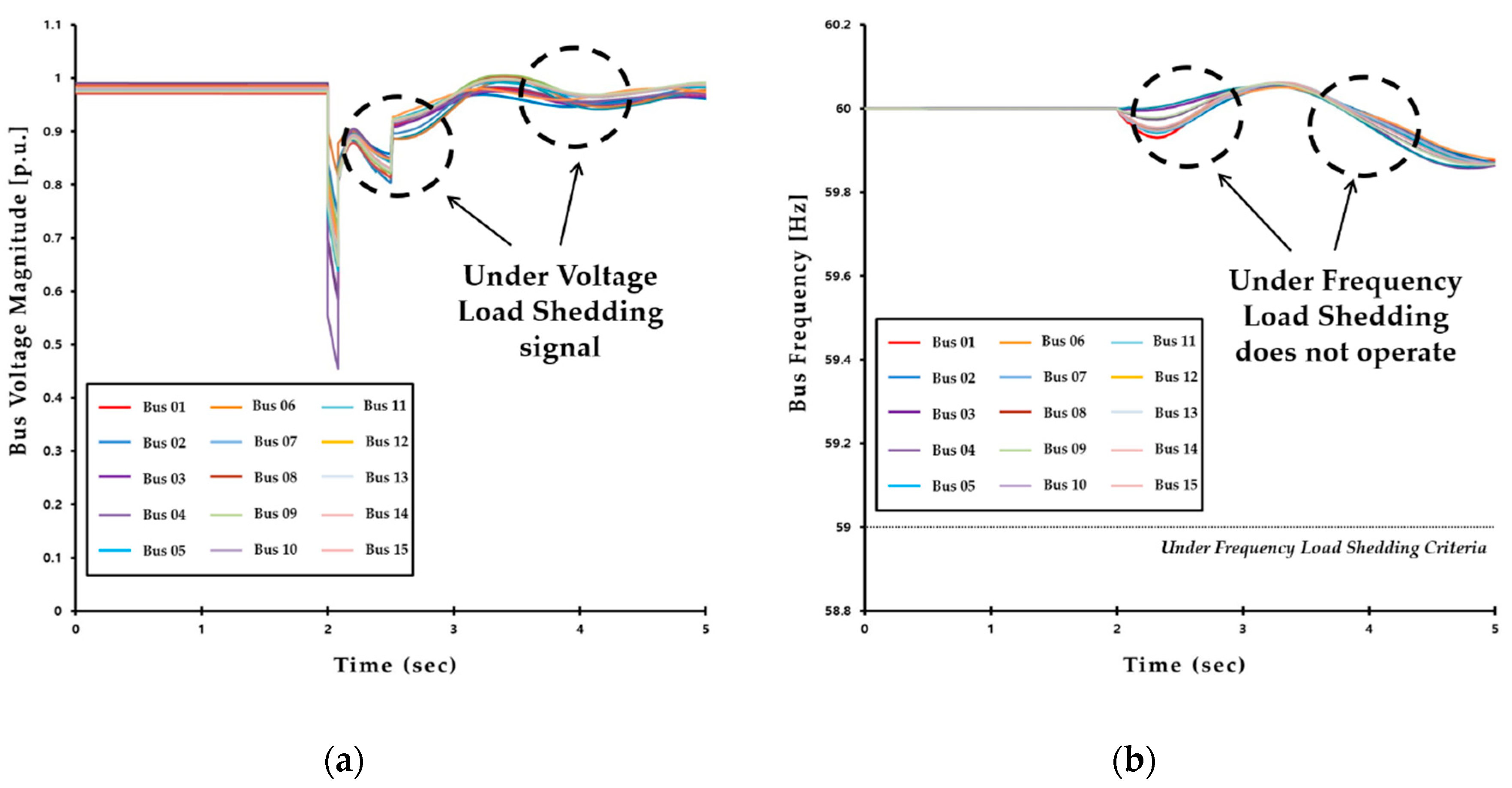
3.3. UVLS Scheme Interaction with the UFLS Scheme

To maintain voltage and frequency stability after disturbances, the UVLS and UFLS schemes can be performed in the Korean power system. Some of the load shedding resources are shared by the two schemes. This section discusses the interaction between the two schemes. When the load is shed by UFLS first, a problem occurs if there is no shedding resources for UVLS. The current load shedding amount for UFLS (approximately 2500 MW) is much larger than that of load shedding by UVLS. Thus, in most of the cases, the system might not suffer from low voltage problems after performing UFLS, even though no resources remain for UVLS.
When the system experiences low frequency problems a few seconds after critical events, the UFLS scheme is activated, and its time delay is about 0.1 s. However, UVLS can determine whether to shed loads within a 1-s time delay when low voltage problems are detected, and it transmits the signal to control locations. Thus, it is obvious that the load shedding signal is already transmitted before the operation of UFLS in low voltage situations. Figure 10a illustrates bus voltage trajectories when UVLS is performed first. In this case, the UVLS signal is transmitted within a short period of time as in Figure 10a. Figure 10b shows bus frequency trajectories after the fault. In this case, the UFLS does not operate because the frequency is not low enough to satisfy the criteria to generate the load shedding signal. After that, UFLS might be activated based on the state changes of the system.
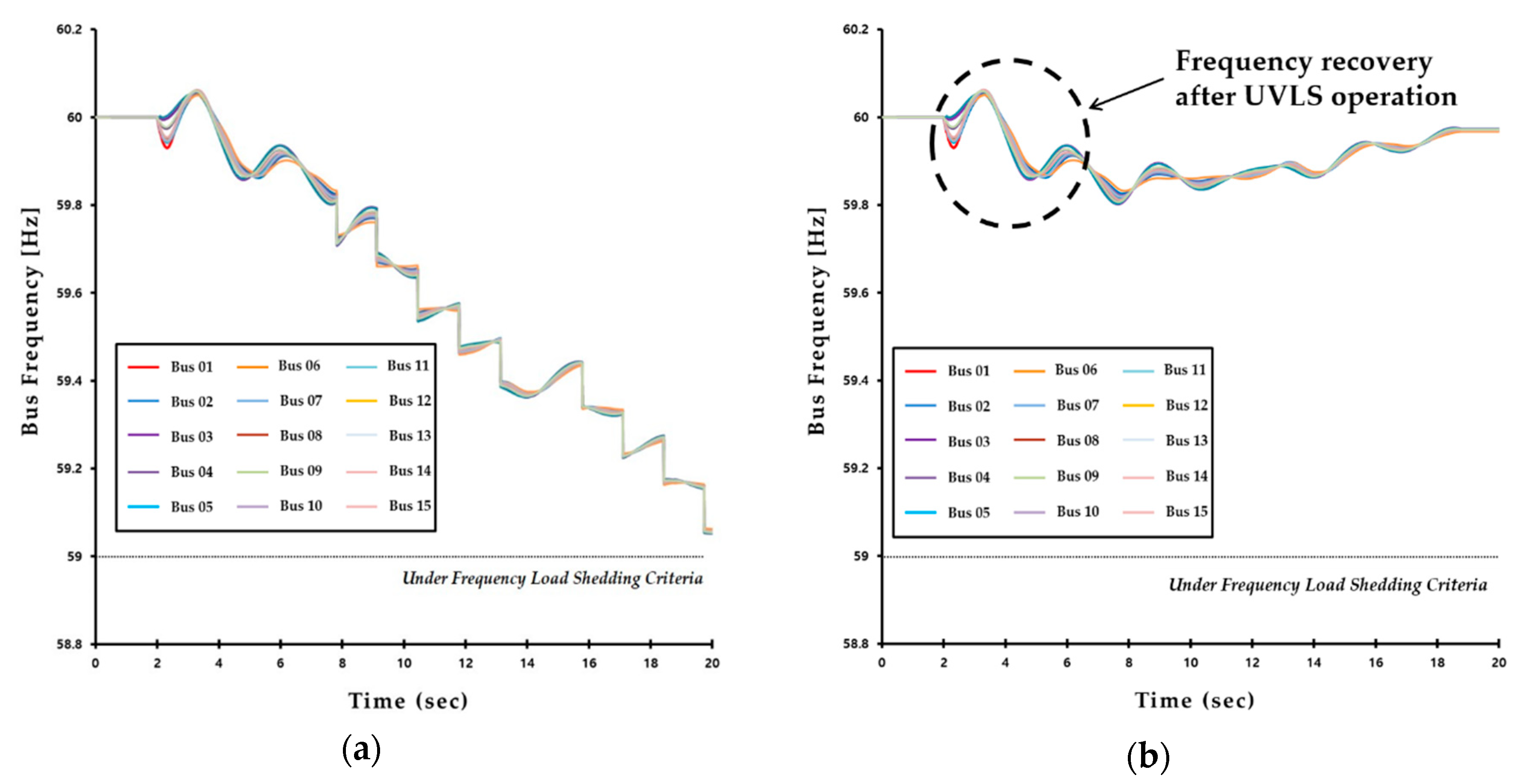
Figure 11 shows the time trajectory result of bus frequency applying the two-circuit outage of 765 kV transmission lines (Sinseosan-Sinansung) in the Korean power system. When an outage occurs on the 765 kV lines, some generators in the Dangjin plant are tripped for angle stability. As in Figure 11, when the load is shed by UVLS, the frequency would recover above the UFLS operating range. Figure 11a illustrates the frequency change before UVLS operation, while Figure 11b shows the frequency variation after UVLS operation. Thus, one can notice from those figures that the operation of UFLS might be prevented depending on the action of the UVLS. In general, the critical frequency drop activating UFLS usually occurs about 10 s after the fault. The proposed load shedding scheme transmits the load shedding signal when the VSMI falls below 10% after a fault to shed the loads of each substation. Therefore, all load interruptions are performed within 4 s after the fault, and the system can be stabilized.

3.4. Discussion

According to the above results, the two load shedding methods are summarized in Table 7. The results of the buses’ voltage recoveries after load shedding are similar, but the total load shedding amount is different between the two methods. As can be seen from Table 7, in the decentralized scheme, the shedding could decrease the amount by about 158 MW. The case studies investigated validate the proposed method, and it was shown to lessen the amount of load shed results compared to the existing scheme.
It is very important to calculate the voltage stability margin index as the basis for determining load shedding in the proposed method. The proposed method’s process is performed based on the VMSI by SMT in a distributed way, and the delay time of shedding the load bus would be determined by VMSI. Therefore, it should be decided very carefully based on the selection of the appropriate reference quantity through the SMT and the experience of the system operator.
Excessive load shedding sometimes leads to an overvoltage problem when the existing scheme is applied. The existing load shedding scheme based on off-line analysis determines the amount of load shedding on the assumption that the system is the most severe condition. In this case, this might lead to economic loss due to unnecessary load shedding even though the actual system does not proceed in an unstable state. The proposed load shedding scheme in this paper can accurately estimate the situation when the load shedding is required by monitoring the system in real time. The system operator can actively cope with an emergency so that unnecessary load shedding can be prevented and effectively stabilize the system. In addition, performing a minimum load shedding to prevent a wide area blackout caused by voltage instability can protect against great economic loss. Furthermore, the decentralized load shedding method based on SMT, considering the system’s dynamic behavior, could improve the voltage stability. In summary, the proposed method exhibited the best performance after load shedding in relation to the steady state from the perspective of voltage stability and contributed to the establishment of an optimal load shedding strategy.

4. Conclusions

In this paper, to overcome the disadvantages of the existing load shedding method, a decentralized load shedding scheme based on the SMT was proposed. SMT was used throughout the proposed load shedding process, and the voltage stability margin was calculated by the PMUs via the measured voltage and current waveforms. Thus, the calculated voltage stability margin can be used as a useful index for the system operators in the critical decision-making process of load shedding. The decentralized load shedding method was applied to the emergency situation to decide whether to shed loads depending on the active power margin. The proposed method significantly reduced the amount of load shedding in comparison to existing load shedding strategies. The case study results show that the decentralized load shedding method could enhance the steady state of power systems’ voltage stability when encountering large disturbances. Additionally, the performances of the proposed load shedding schemes were tested using dynamic simulations of the Korean power system, and the extensive results demonstrated the effectiveness of the decentralized load shedding method. Thus, utilizing the proposed scheme in the PMU application within the practical system, there would be a contribution to protecting the system safely and efficiently.
Future research work will focus on the cyber security of the PMU application. Electronic communication links are an important component of the SMT and bring associated concerns about cyber security. Given that most of the power systems evolve in an electronically-controlled environment, a successful cyber-attack could cause enormous physical and financial damage. In addition, if the control equipment is hacked and an appropriate countermeasure is not taken in case of an accident, the stability of the whole system might be degraded. Therefore, it is essential that cyber security vulnerabilities be carefully analyzed and mitigation countermeasures prepared.

Author Contributions

Y.L. conceived of and designed the research, performed the system simulations and wrote the paper. H.S. supervised the research and made suggestions for this research.

Acknowledgments

This research was supported by the Human Resources Development of the Korea Institute of Energy Technology Evaluation and Planning (KETEP) grant funded by the Korea government Ministry of Trade, Industry & Energy (20174030201840).

Conflicts of Interest

The authors declare no conflict of interest.

References

  1. Bi, T.; Qin, J.; Yan, Y.; Liu, H.; Martin, K. An approach for estimating disturbance arrival time based on structural frame model. IEEE Trans. Power Syst. 2017, 32, 1741–1750. [Google Scholar] [CrossRef]
  2. Andersson, G.; Donalek, P.; Farmer, R.; Hatziargyriou, N.; Kamwa, I.; Kundur, P. Causes of the 2003 major grid blackouts in North America and Europe, and recommended means to improve system dynamic performance. IEEE Trans. Power Syst. 2005, 20, 1922–1928. [Google Scholar] [CrossRef]
  3. Morison, G.K.; Gao, B.; Kundur, P. Voltage stability analysis using static and dynamic approaches. IEEE Trans. Power Syst. 1993, 8, 1159–1171. [Google Scholar] [CrossRef]
  4. Kundur, P.; Paserba, J.; Ajjarapu, V.; Andersson, G.; Bose, A.; Canizares, C.; Van Cutsem, T.; Hatziargyriou, N.; Hill, D.; Stankovic, A.; et al. Definition and classification of power system stability. IEEE Trans. Power Syst. 2004, 19, 1387–1401. [Google Scholar]
  5. Ladhani, S.S.; Rosehart, W. Under voltage load shedding for voltage stability overview of concepts and principles. In Proceedings of the Power Engineering Society General Meeting, Denver, CO, USA, 6–10 June 2004; pp. 1597–1602. [Google Scholar]
  6. Sapari, N.M.; Mokhlis, H.; Laghari, J.A.; Bakar, A.H.A.; Dahalan, M.R.M. Application of load shedding schemes for distribution network connected with distributed generation: A review. Renew. Sustain. Energy Rev. 2018, 82, 858–867. [Google Scholar] [CrossRef]
  7. Verayiah, R.; Mohamed, A.; Shareef, H.; Abidin, I.Z. Review of under-voltage load shedding schemes in power system operation. Przegląd Elektrotechniczny 2014, 90, 99–103. [Google Scholar]
  8. Kaffashan, I.; Mortezaee, S.; Amraee, T. A robust undervoltage load shedding scheme against voltage instability. Turk. J. Electr. Eng. Comput. Sci. 2016, 24, 3309–3320. [Google Scholar] [CrossRef]
  9. Majidi, M.; Aghamohammadi, M.R.; Manbachi, M. New design of intelligent load shedding algorithm based on critical line overloads to reduce network cascading failure risks. Turk. J. Electr. Eng. Comput. Sci. 2014, 22, 1395–1409. [Google Scholar] [CrossRef]
  10. Popović, D.S.; Levi, V.A.; Gorečan, Z.A. Co-ordination of emergency secondary-voltage control and load shedding to prevent voltage instability. IEE Proc.-Gen. Transm. Distrib. 1997, 144, 293–300. [Google Scholar] [CrossRef]
  11. Schlueter, R.A. A voltage stability security assessment method. IEEE Trans. Power Syst. 1998, 13, 1423–1438. [Google Scholar] [CrossRef]
  12. KEPCO Research Institute. Available online: https://www.kepri.re.kr:20808/ (accessed on 29 August 2018).
  13. Shahriar, M.S.; Habiballah, I.O.; Hussein, H. Optimization of Phasor Measurement Unit (PMU) Placement in Supervisory Control and Data Acquisition (SCADA)-Based Power System for Better State-Estimation Performance. Energies 2018, 11, 570. [Google Scholar] [CrossRef]
  14. Wang, Y.; Pordanjani, I.R.; Li, W.; Xu, W.; Chen, T.; Vaahedi, E.; Gurney, J. Voltage stability monitoring based on the concept of coupled single-port circuit. IEEE Trans. Power Syst. 2011, 26, 2154–2163. [Google Scholar] [CrossRef]
  15. Milosevic, B.; Begovic, M. Voltage-stability protection and control using a wide-area network of phasor measurements. IEEE Trans. Power Syst. 2003, 18, 121–127. [Google Scholar] [CrossRef]
  16. Mahari, A.; Seyedi, H. A wide area synchrophasor-based load shedding scheme to prevent voltage collapse. Int. J. Electr. Power Energy Syst. 2016, 78, 248–257. [Google Scholar] [CrossRef]
  17. Corsi, S. Wide area voltage protection. IET Gen. Transm. Distrib. 2010, 4, 1164–1179. [Google Scholar] [CrossRef]
  18. Derafshian, M.; Amjady, N.; Dehghan, S. Special protection scheme against voltage collapse. IET Gen. Transm. Distrib. 2016, 10, 341–351. [Google Scholar] [CrossRef]
  19. Smon, I.; Verbic, G.; Gubina, F. Local voltage-stability index using Tllegen’s theorem. IEEE Trans. Power Syst. 2006, 21, 1267–1275. [Google Scholar] [CrossRef]
  20. Adewole, A.C.; Tzoneva, R.; Apostolov, A. Adaptive under-voltage load shedding scheme for large interconnected smart grids based on wide area synchrophasor measurements. IET Gen. Transm. Distrib. 2016, 10, 1657–1968. [Google Scholar] [CrossRef]
  21. De La Ree, J.; Centeno, V.; Thorp, J.S.; Phadke, A.G. Synchronized phasor measurement applications in power systems. IEEE Trans. Smart Grid 2010, 1, 20–27. [Google Scholar] [CrossRef]
  22. Cirio, D.; Lucarella, D.; Giannuzzi, G.; Tuosto, F. Wide area monitoring in the Italian power system: Architecture, functions and experiences. Eur. Trans. Electr. Power 2010, 21, 1541–1556. [Google Scholar] [CrossRef]
  23. Nezam-Sarmadi, S.A.; Nourizadeh, S.; Azizi, S.; Rahmat-Samii, R.; Ranjbar, A.M. A power system build-up restoration method based on wide area measurement systems. Euro. Trans. Electr. Power 2011, 21, 712–720. [Google Scholar] [CrossRef]
  24. Chow, J.H. Power system measurement data and their applications. Euro. Trans. Electr. Power 2011, 21, 1493–1495. [Google Scholar] [CrossRef]
  25. Tang, J.; Liu, J.; Ponci, F.; Monti, A. Adaptive load shedding based on combined frequency and voltage stability assessment using synchrophasor measurements. IEEE Trans. Power Syst. 2013, 28, 2035–2047. [Google Scholar] [CrossRef]
  26. Karlsson, D.; Hemmingsson, M.; Lindahl, S. Wide area system monitoring and control-terminology, phenomena, and solution implementation strategies. IEEE Power Energy Mag. 2018, 2, 68–76. [Google Scholar] [CrossRef]
  27. Xie, X.; Xin, Y.; Xiao, J.; Wu, J.; Han, Y. WAMS applications in Chinese power systems. IEEE Power Energy Mag. 2006, 4, 54–63. [Google Scholar]
  28. Zima, M.; Larsson, M.; Korba, P.; Rehtanz, C.; Andersson, G. Design aspects for wide-area monitoring and control systems. Proc. IEEE 2005, 93, 980–996. [Google Scholar] [CrossRef]
  29. Vu, K.; Begovic, M.M.; Novosel, D.; Saha, M.M. Use of local measurements to estimate voltage-stability margin. IEEE Trans. Power Syst. 1999, 14, 1029–1035. [Google Scholar] [CrossRef]
  30. Glavic, M.; Van Cutsem, T. Wide-area detection of voltage instability from synchronized phasor measurements. Part I: Principle. IEEE Trans. Power Syst. 2009, 24, 1408–1416. [Google Scholar] [CrossRef]
  31. Glavic, M.; Van Cutsem, T. Wide-area detection of voltage instability from synchronized phasor measurements. Part II: Simulation results. IEEE Trans. Power Syst. 2009, 24, 1417–1425. [Google Scholar] [CrossRef]
  32. Phadke, A.G.; Thorp, J.S. Synchronized Phasor Measurements and Their Applications; Springer: New York, NY, USA, 2008. [Google Scholar]
  33. Phadke, A.G.; de Moraes, R.M. The wide world of wide-area measurement. IEEE Power Energy Mag. 2008, 6, 52–65. [Google Scholar] [CrossRef]
  34. Burnett, R.O.; Butts, M.M.; Cease, T.W.; Centeno, V.; Michel, G.; Murphy, R.J.; Phadke, A.G. Synchronized phasor measurements of a power system event. IEEE Trans. Power Syst. 1994, 9, 1643–1650. [Google Scholar] [CrossRef]
  35. Kim, H.; Kinoshita, T.; Kim, T. A bankruptcy problem approach to load-shedding in multiagent-based microgrid operation. Sensors 2010, 10, 8888–8898. [Google Scholar] [CrossRef] [PubMed]
  36. Hosseinzadeh, M.; Rajaei, F. Supervisory Control of a Hybrid AC/DC Micro-Grid with Load Shedding Based on the Bankruptcy Problem. AUT J. Model. Simul. 2016, 48, 3–12. [Google Scholar]
  37. Martin, K.E.; Benmouyal, G.; Adamiak, M.G.; Begovic, M.; Burnett, R.O.; Carr, K.R.; Cobb, A.; Kusters, J.A.; Horowitz, S.H.; Jensen, G.R.; et al. IEEE Standard for Synchrophasor Measurements for Power Systems. IEEE Trans. Power Deliv. 2011, 13, 73–77. [Google Scholar] [CrossRef]
  38. Zhang, P.; Chen, J.; Shao, M. Phasor Measurement Unit (PMU) Implementation and Applications; Electric Power Research Institute: Palo Alto, CA, USA, 2007. [Google Scholar]
  39. Patil, G.C.; Thosar, A.G. Application of synchrophasor measurements using PMU for modern power systems monitoring and control. In Proceedings of the 2017 International Conference on Computation of Power, Energy, Information and Communication, Melmaruvathur, India, 22–23 March 2017; pp. 754–760. [Google Scholar]
  40. Kim, J.; Lee, B.; Han, S.; Shin, J.H.; Kim, T.; Kim, S.; Moon, Y. Study of the effectiveness of a Korean smart transmission grid based on synchro-phasor data of K-WAMS. IEEE Trans. Smart Grid 2013, 4, 411–418. [Google Scholar] [CrossRef]
  41. Taylor, C.W.; Erickson, D.C.; Martin, K.E.; Wilson, R.E.; Venkatasubramanian, V. WACS-wide-area stability and voltage control system: R&D and online demonstration. Proc. IEEE 2005, 93, 892–906. [Google Scholar]
  42. Adamiak, M.; Kasztenny, B.; Permerlani, W. Synchranopasors: Defination, measurement, and application. In Proceedings of the 59th Annu. Georgia Tech Protective Relaying, Atlanta, GA, USA, 27–29 April 2005. [Google Scholar]
  43. Cho, J.H.; Choi, M.H.; Lee, M.W.; Kim, S.T.; Woo, D.J. Study on WAMAC System Architecture Design, Including PMU Data Verification System. KIPS Trans. Comput. Commun. Syst. 2012, 1, 181–186. [Google Scholar] [CrossRef]
  44. Electric Power Research Institute. Real-Time Application of Phasor Measurement Unit (PMU) for Visualization, Reactive Power Monitoring and Voltage Stability Protection; New York State Energy Research and Development Authority: New York, NY, USA, 2011.
  45. Min, D.; Kim, S.J.; Seo, S.; Moon, Y.H.; Sun, K.; Chow, J.H.; Hur, K. Computing Safety Margins of a Generation Rejection Scheme: A Framework for Online Implementation. IEEE Trans. Smart Grid 2018, 9, 2337–2346. [Google Scholar] [CrossRef]
  46. Abed, A.M. WSCC voltage stability criteria, undervoltage load shedding strategy, and reactive power reserve monitoring methodology. In Proceedings of the Power Engineering Society Summer Meeting, Edmonton, AB, Canada, 18–22 July 1999; pp. 191–197. [Google Scholar]
Figure 1. Configuration of PMU implementation architecture.
Electronics 07 00277 g001
Figure 2. PMU application in the WAMAC system.
Electronics 07 00277 g002
Figure 3. Thévenin equivalent of a system.
Electronics 07 00277 g003
Figure 4. Concept of decentralized load shedding method.
Electronics 07 00277 g004
Figure 5. Flowchart of the proposed decentralized load shedding method.
Electronics 07 00277 g005
Figure 6. Voltage profile of the Korean power system for a fault of the 765 kV line.
Electronics 07 00277 g006
Figure 7. Observation for the bus voltage profile with existing load shedding.
Electronics 07 00277 g007
Figure 8. Observation for the real-time active power margin.
Electronics 07 00277 g008
Figure 9. Observation for the bus voltage profile with the proposed load shedding.
Electronics 07 00277 g009
Figure 10. UVLS load shedding signal transmission interval and variation of frequency. (a) Bus voltage magnitude. (b) Bus frequency.
Electronics 07 00277 g010
Figure 11. Variation of frequency depending on UVLS operation. (a) Without UVLS. (b) With UVLS.
Electronics 07 00277 g011
Table 1. The final goal of the load shedding scheme.
Classification1st Level2nd Level3rd Level
Monitoring InformationRelaySCADA/EMSSynchrophasor
Analysis MethodOff-lineOff-lineOn-line
Load Shedding CriterionSteady state DynamicReal-time
Load Shedding AmountFixedVariableVariable
Load Shedding MethodSingle-stepMulti-stepMulti-step
Table 2. Implementation procedures of existing load shedding.
StepTime (s)Description
12.0000765 kV transmission line fault
22.0833Clear fault
32.1500Disconnect generators
42.5000Load shedding
520.000Observation of the bus voltage
Table 3. The location, delay time and amount of the existing load shedding scheme.
Location (#)Delay Time (s)Amount (MW)
# Bus 012.500057.8990
# Bus 022.500024.9890
# Bus 032.500034.7700
# Bus 042.500098.7220
# Bus 052.5000119.698
# Bus 062.500056.1420
# Bus 072.5000104.393
# Bus 082.5000212.936
# Bus 092.5000156.836
# Bus 102.500059.3480
# Bus 112.500087.5700
# Bus 122.500094.0660
# Bus 132.500039.2940
# Bus 142.50006.33000
# Bus 152.5000117.298
Table 4. Implementation procedures of existing load shedding.
StepTime (s)Description
12.0000765 kV transmission line fault
22.0833Clear fault
32.1500Disconnect generators
4~20.000Implement load shedding when the active power margin is below 10% of the pre-contingency margin
520.000Observation of the bus voltage
Table 5. Result of the active power margin before and after the contingency.
Bus No.Pre-ContingencyPost-ContingencyClassification
# Bus 011401.500.00000Implement load shedding
# Bus 041391.500.00000
# Bus 05992.6700.00000
# Bus 06311.2100.00000
# Bus 07775.4300.00000
# Bus 08731.1600.00000
# Bus 091011.900.00000
# Bus 111060.100.00000
# Bus 12681.6400.00000
# Bus 14795.1200.00000
# Bus 15807.4301.84130
# Bus 021203.201121.40Non-Implement load shedding
# Bus 031427.001321.10
# Bus 101096.30997.210
# Bus 13891.230837.620
Table 6. The location, delay time and amount of the existing load shedding scheme.
Location (#)Delay Time (s)Amount (MW)
# Bus 052.3835119.698
# Bus 072.3988104.393
# Bus 062.417856.1420
# Bus 092.4805156.836
# Bus 142.50906.33000
# Bus 082.5159212.936
# Bus 152.5824117.298
# Bus 042.592398.7220
# Bus 125.289994.0660
# Bus 115.964987.5700
# Bus 015.989957.8990
Table 7. Comparison of the existing and proposed load shedding method.
MethodObservation of the Bus VoltageAmount of Load Shedding
ExistingAll bus voltages have recovered to above 90% of the pre-contingency voltage1270 [MW]
ProposedAll bus voltages have recovered to above 90% of the pre-contingency voltage1112 [MW]

