Real-Time Particle Swarm Optimization on FPGA for the Optimal Message-Chain Structure


Abstract
:1. Introduction
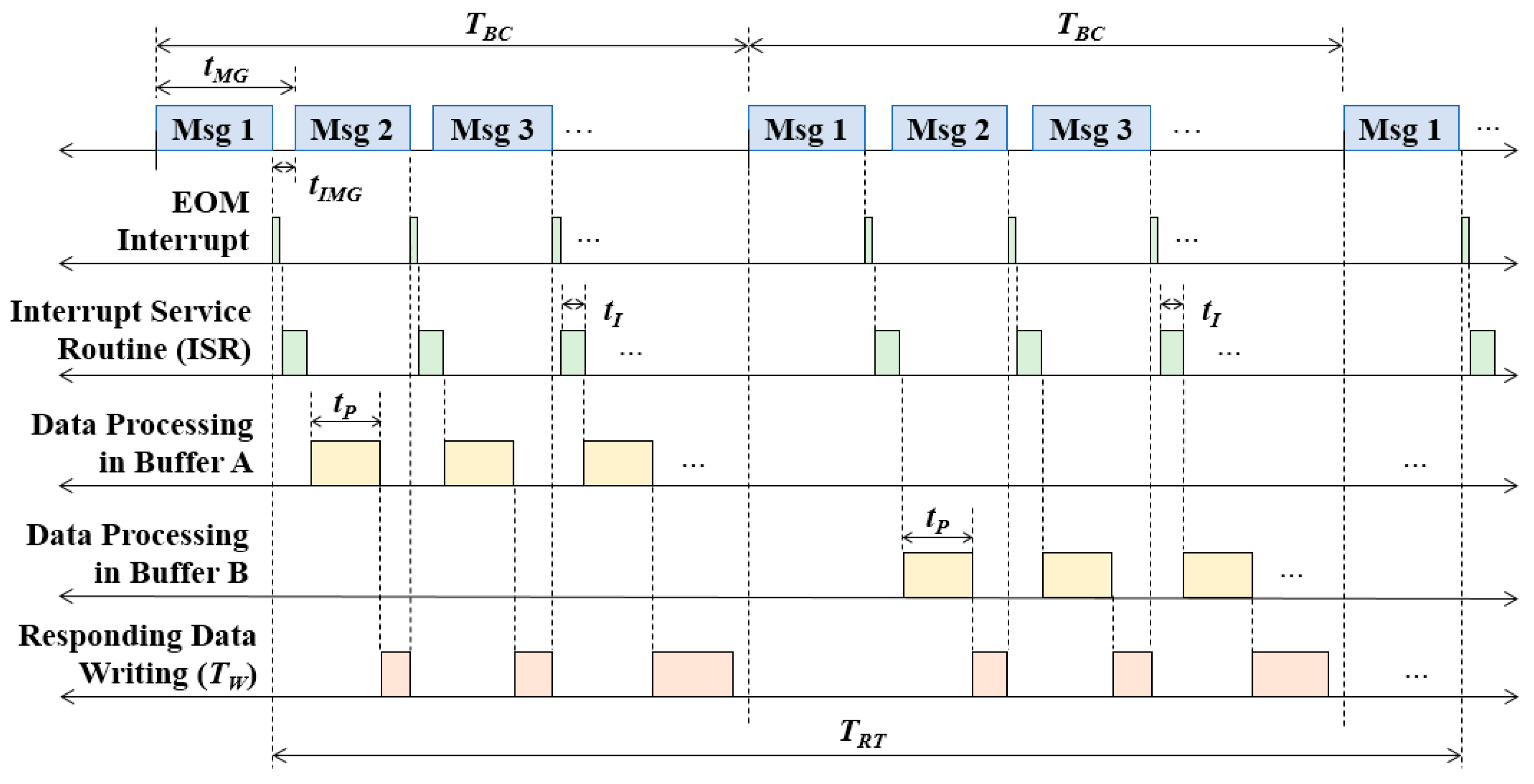
2. Optimization Problem of Message-Chain Structures
3. Real-Time PSO on FPGA
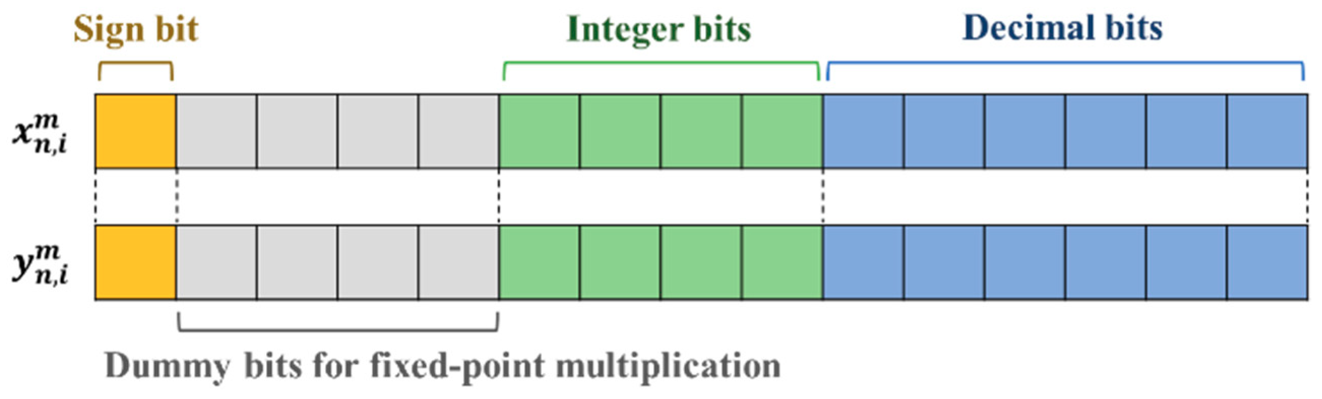
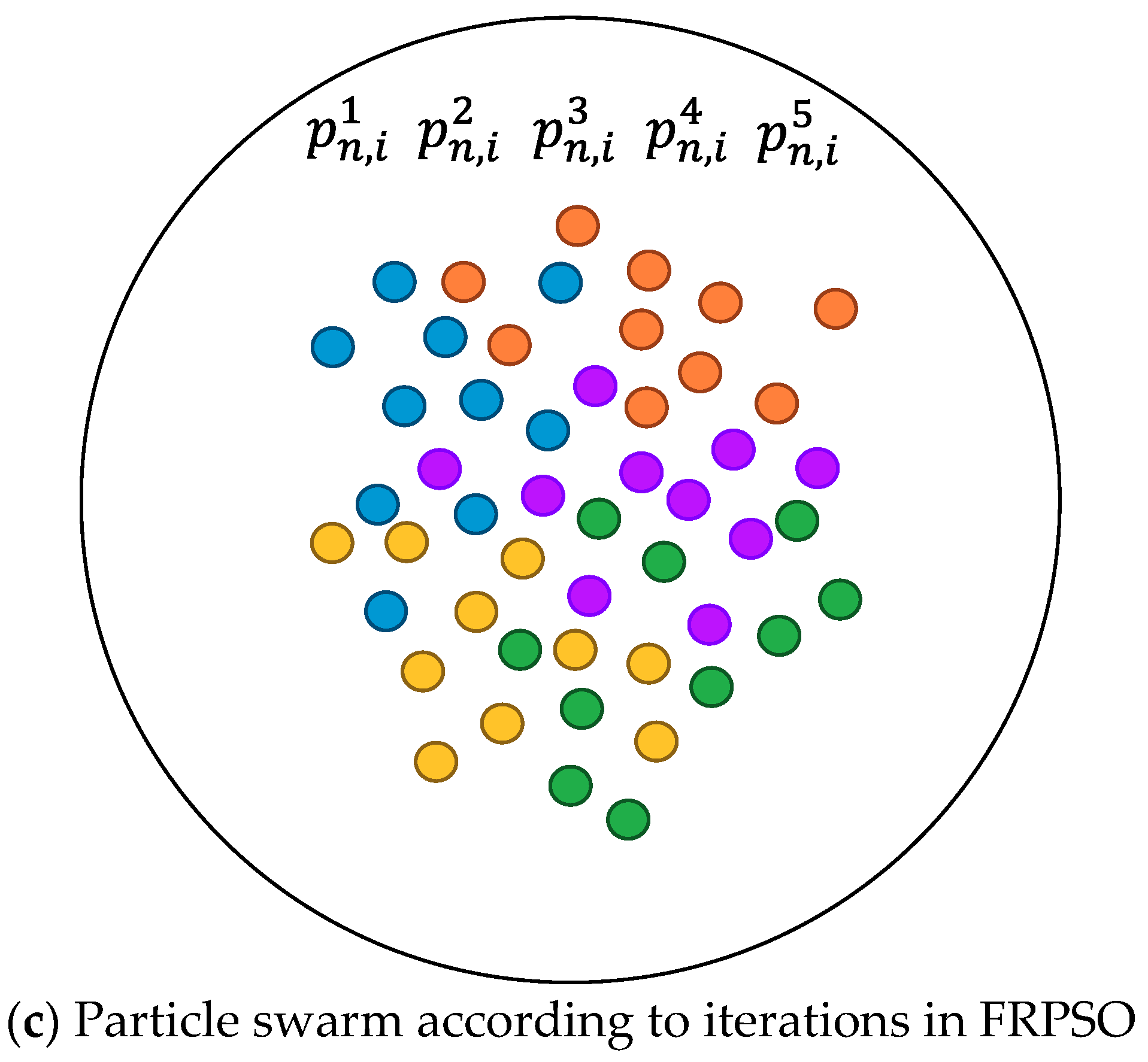
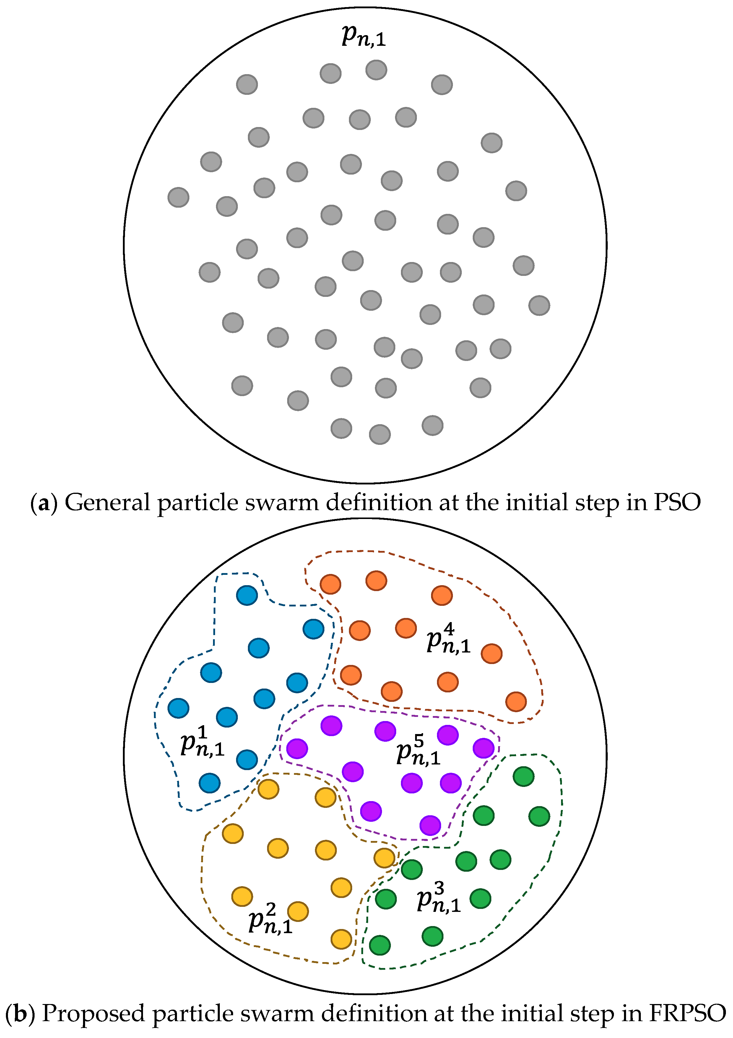
3.1. Particle and Swarm Definition
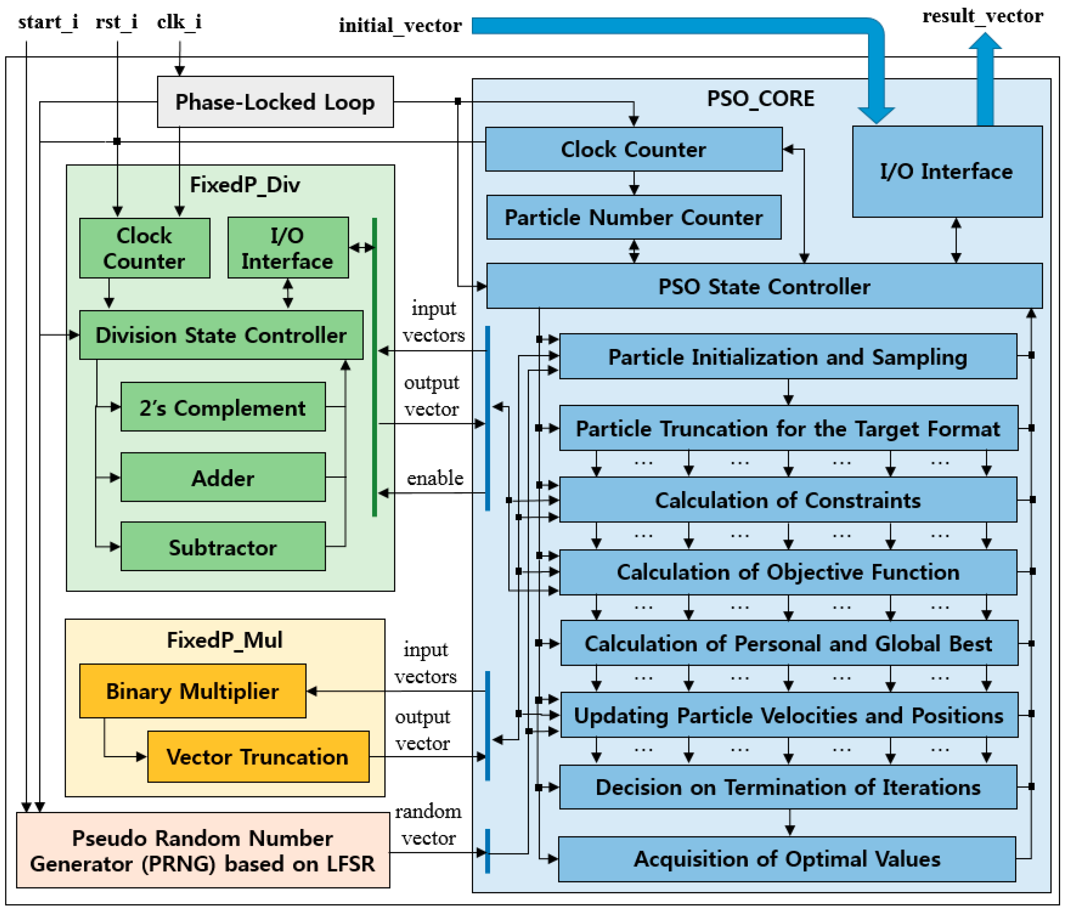
3.2. FPGA Structure
3.3. Core Algorithm
4. Implementation, Simulations, and Evaluations
4.1. Implementation
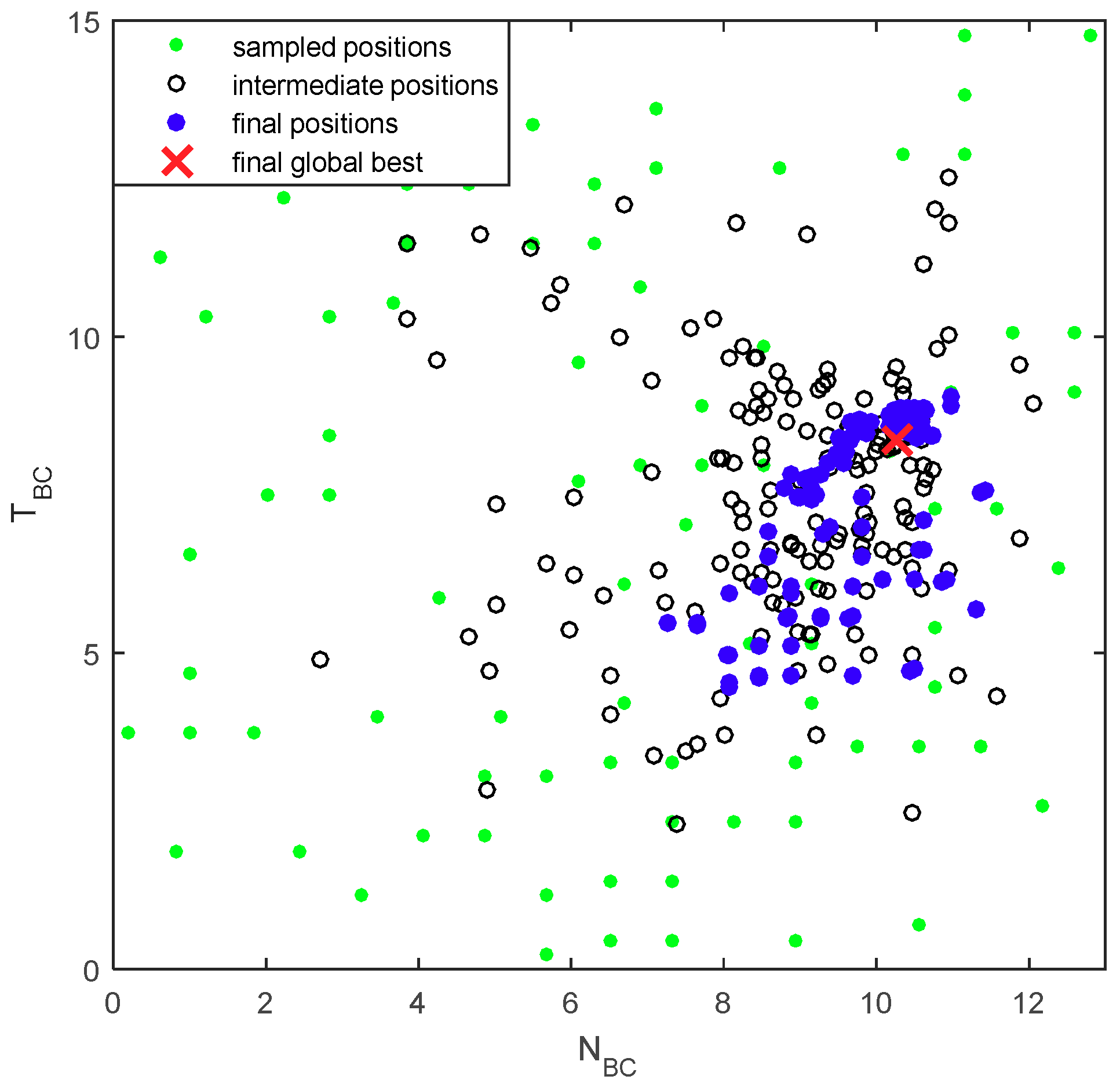
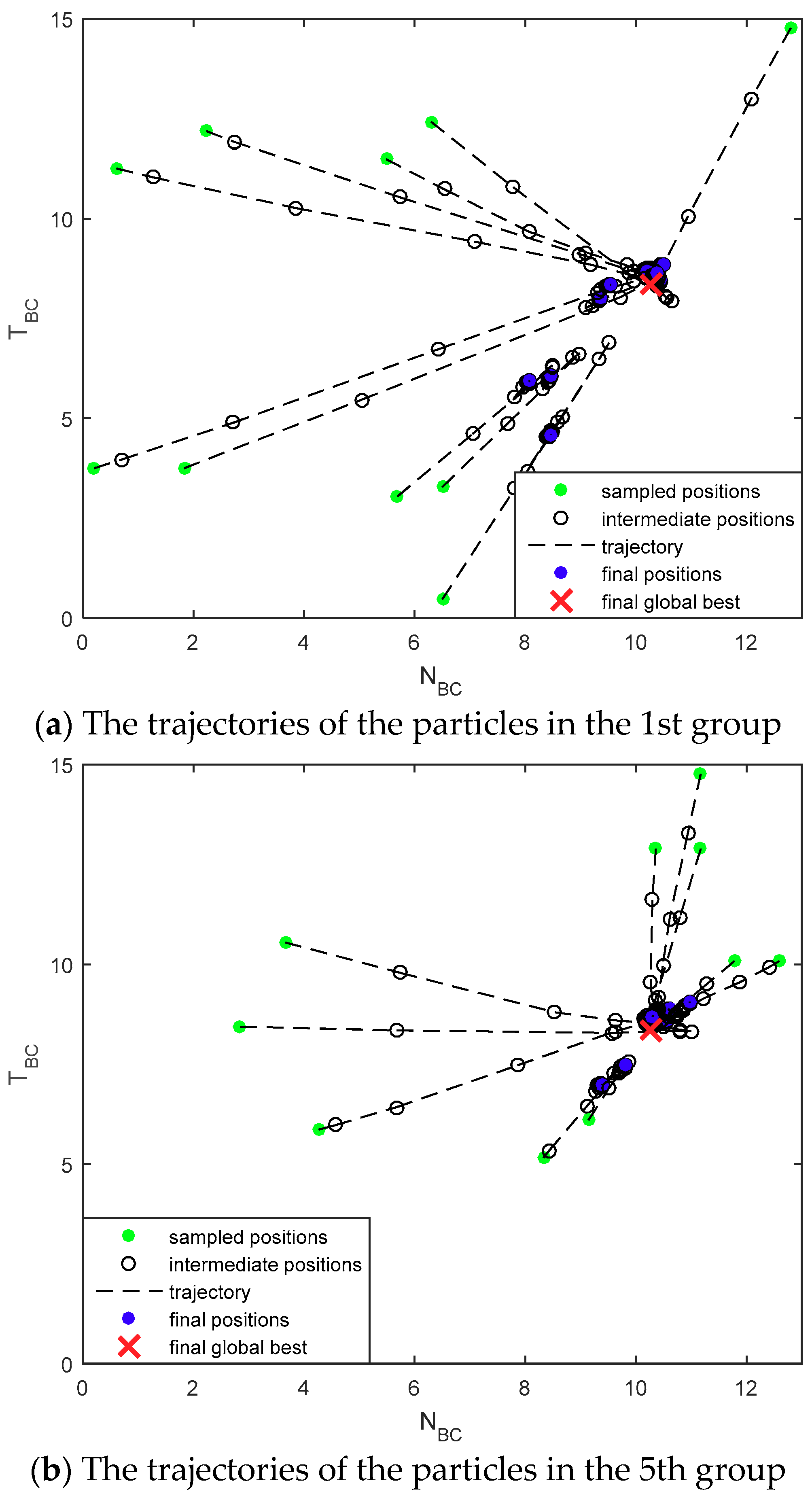
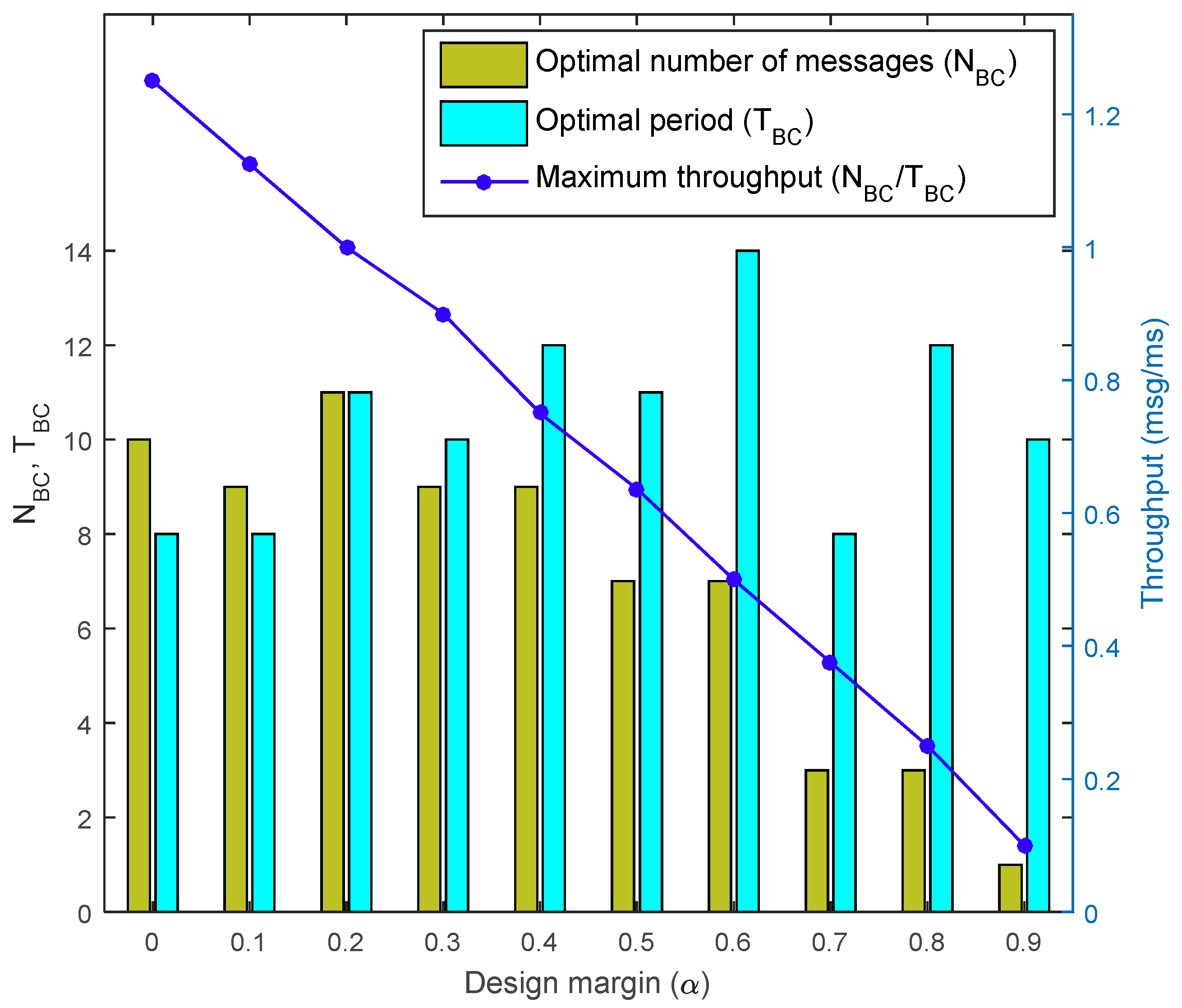
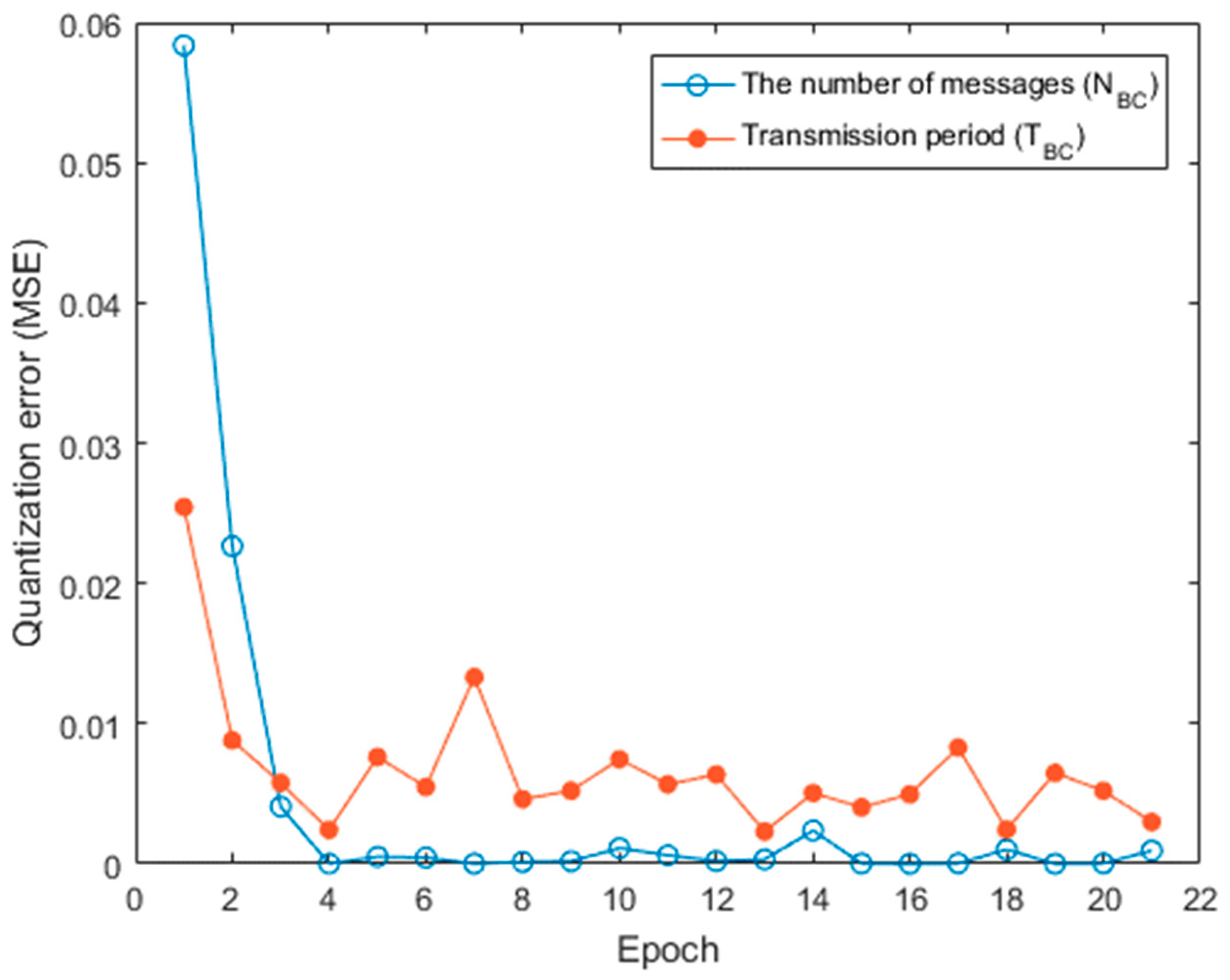
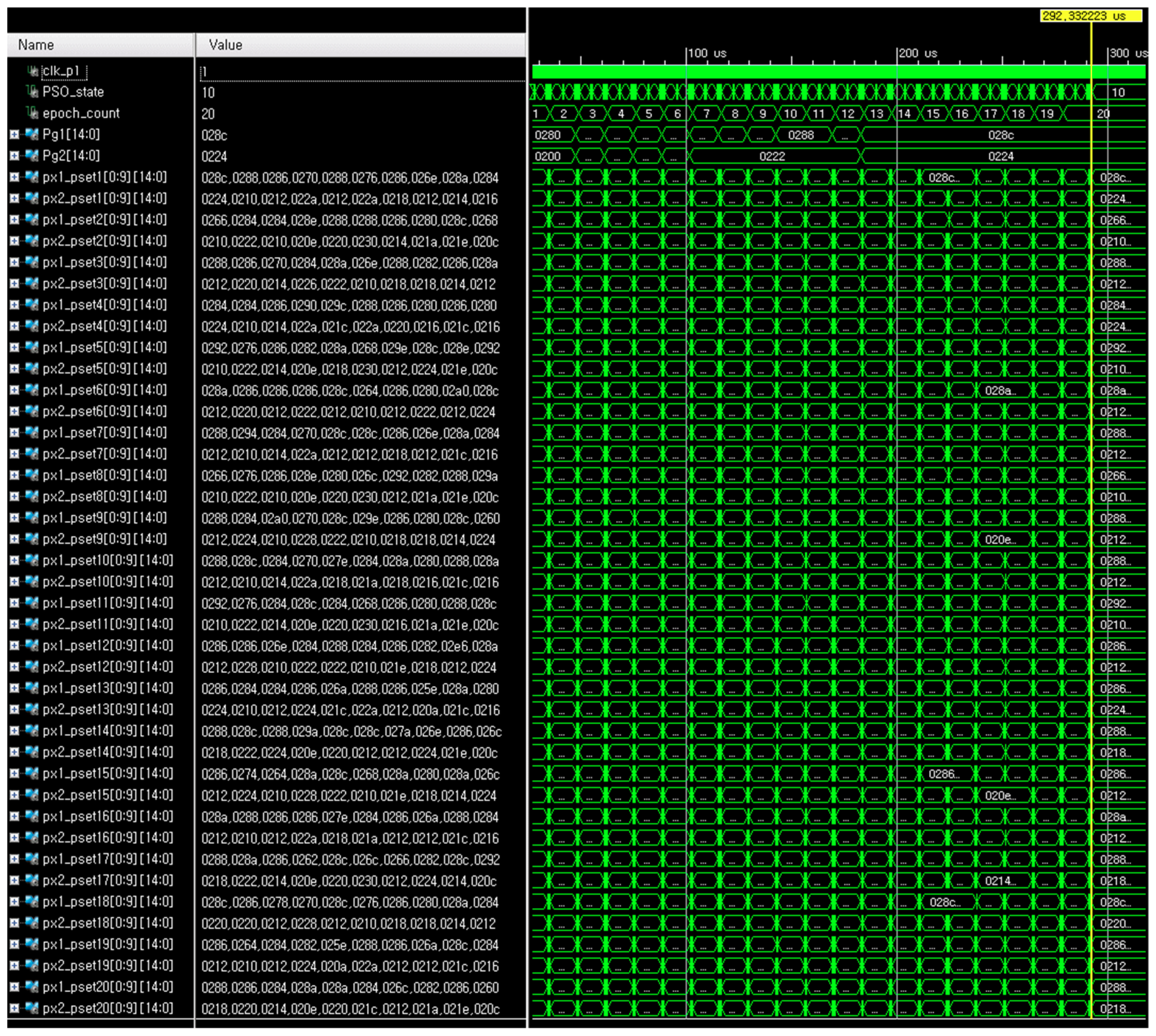
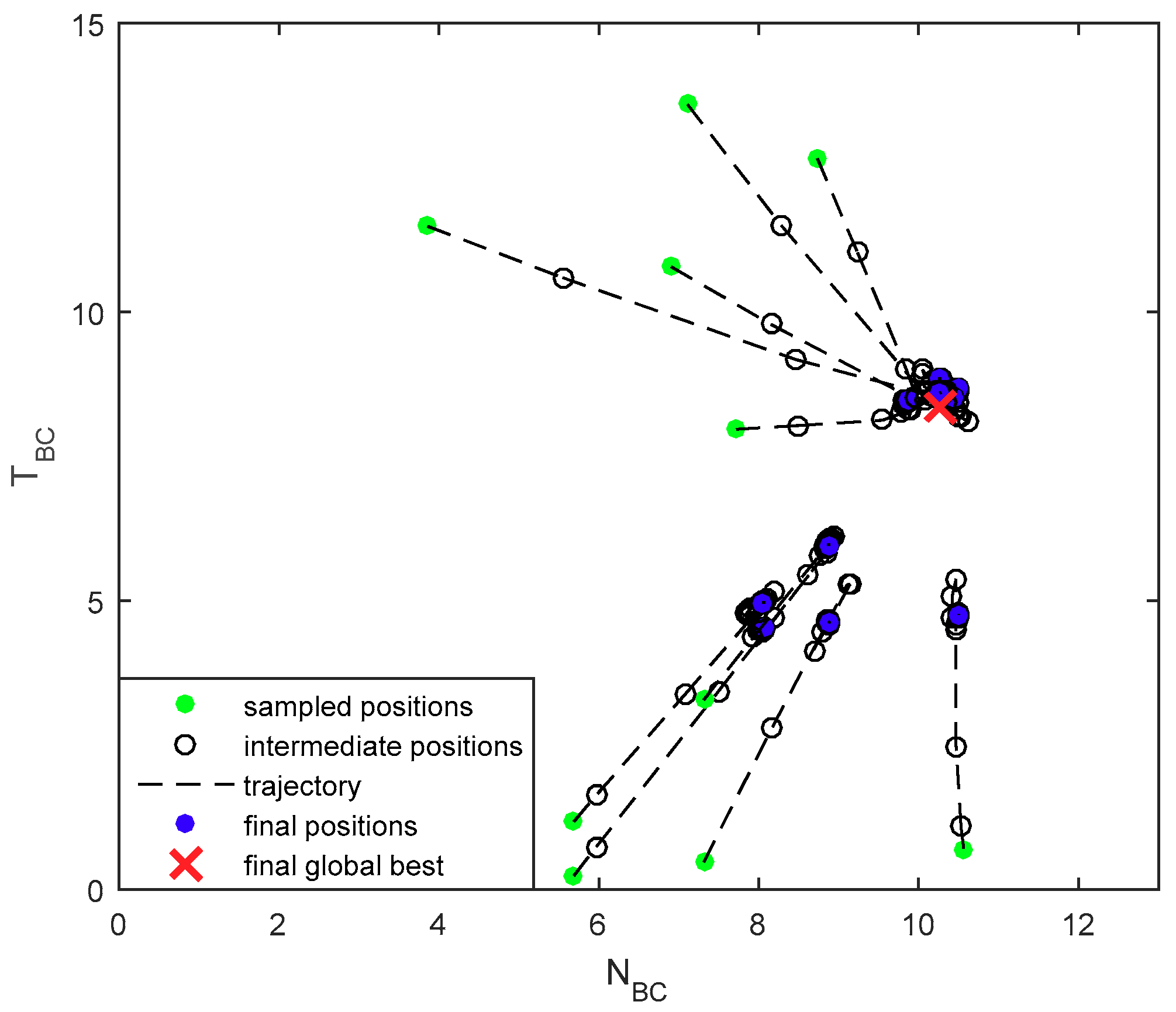
4.2. Simulation Results
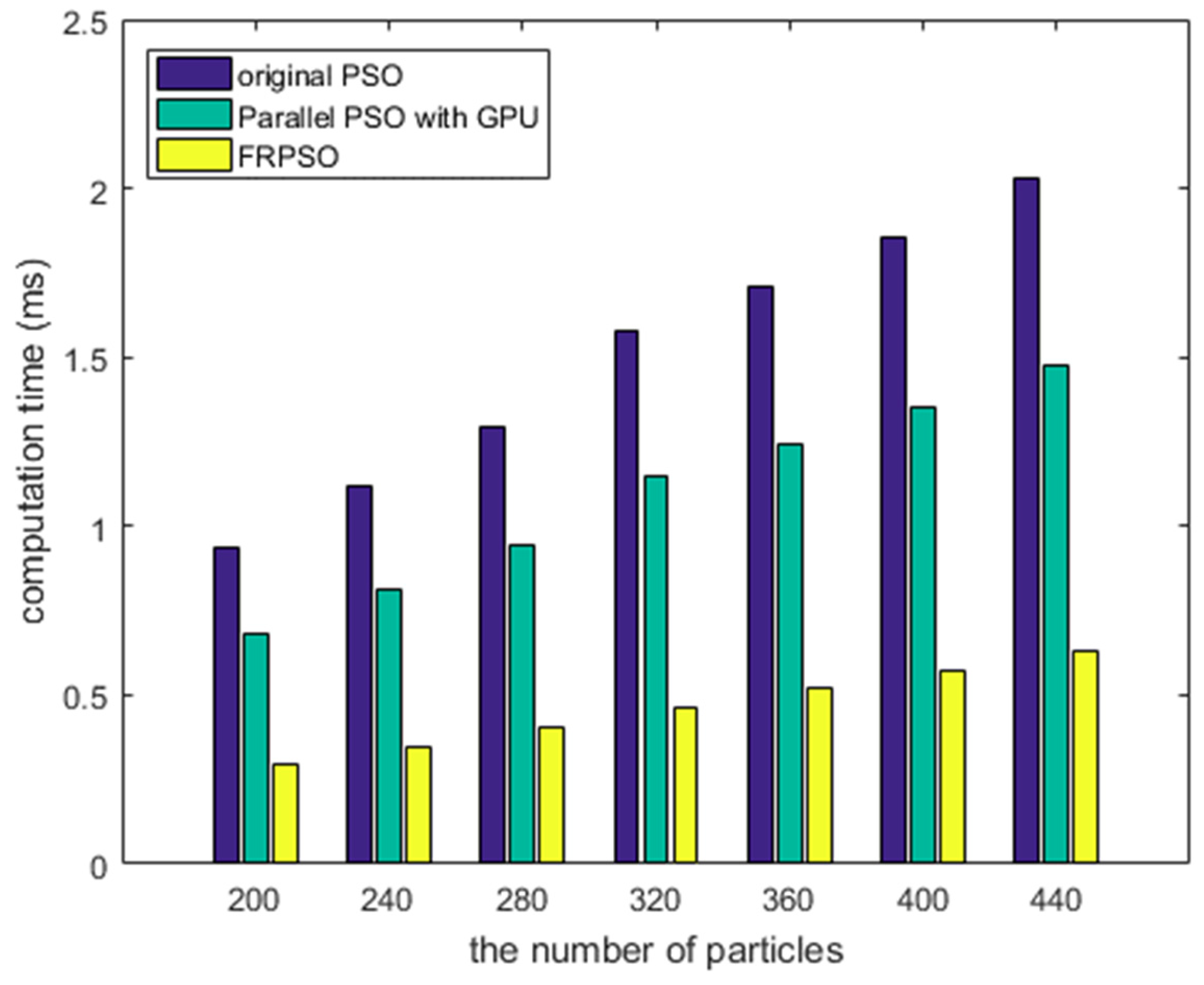
4.3. Evaluations
5. Conclusions
Author Contributions
Funding
Conflicts of Interest
References
- MIL-STD-1553B NOTICE II; Department of Defense: Washington, DC, USA, 1986.
- MIL-STD-1553B Designer’s Guide; Data Device Corporation: Bohemia, NY, USA, 1998.
- Zhang, J.; Liu, M.; Shi, G.; Pan, W. A MIL-STD-1553B bus command optimization algorithm based on load balance. Appl. Mech. Mater. 2012, 130–134, 3839–3842. [Google Scholar] [CrossRef]
- Kim, K.P.; Ahn, K.-H.; Kwon, Y.-S.; Yun, S.-J.; Lee, S.-H. Analysis and implementation of high speed data processing technology using multi-message chain and double buffering method with MIL-STD-1553B. J. Korea Inst. Mil. Sci. Technol. 2013, 16, 422–429. [Google Scholar] [CrossRef]
- Kennedy, J.; Eberhart, R. Particle swarm optimization. In Proceedings of the 1995 IEEE International Conference on Neural Networks, Perth, Australia, 27 November–1 December 1995; pp. 1942–1948. [Google Scholar]
- Lee, H.C.; Park, S.K.; Choi, J.S.; Lee, B.H. PSO-FastSLAM: An improved FastSLAM framework using particle swarm optimization. In Proceedings of the IEEE International Conference Systems, Man, and Cybernetics, San Antonio, TX, USA, 11–14 October 2009; pp. 2763–2768. [Google Scholar]
- Zhang, J.; Ni, L.; Xie, C.; Tan, Y.; Tang, Z. AMT-PSO: An adaptive magnification transformation based particle swarm optimizer. IEICE Trans. Inf. Syst. 2011, E94-D, 786–797. [Google Scholar] [CrossRef]
- Ishikawa, K.; Hayashi, N.; Takai, S. Consensus-based distributed particle swarm optimization with event-triggered communication. IEICE Trans. Fundam. Commun. Comput. Sci. 2018, E101-A, 338–344. [Google Scholar] [CrossRef]
- Liu, W.; Chung, I.; Liu, L.; Leng, S.; Cartes, D.A. Real-time particle swarm optimization based current harmonic cancellation. Eng. Appl. Artif. Intell. 2011, 24, 132–141. [Google Scholar] [CrossRef]
- Gao, Z.; Zeng, X.; Wang, J.; Liu, J. FPGA implementation of adaptive IIR filters with particle swarm optimization algorithm. In Proceedings of the ICCS 2008. 11th IEEE Singapore International Conference on Communication Systems, Guangzhou, China, 19–21 November 2008; pp. 1364–1367. [Google Scholar]
- Gupta, L.; Mehra, R. Modified PSO based Adaptive IIR Filter Design for System Identification on FPGA. Int. J. Comput. Appl. 2011, 22, 1–7. [Google Scholar] [CrossRef]
- Vasumathi, B.; Moorthi, S. Implementation of hybrid ANN–PSO algorithm on FPGA for harmonic estimation. Eng. Appl. Artif. Intell. 2012, 25, 476–483. [Google Scholar] [CrossRef]
- Morsi, N.N.; Abdelhalim, M.B.; Shehata, K.A. FPGA Implementation of PSO-Based Object Tracking System Using SSIM. In Proceedings of the International Conference on Micro-electronics, Beirut, Lebanon, 15–18 December 2013; pp. 1–4. [Google Scholar]
- Trimeche, A.; Sakly, A.; Mtibaa, A. Implementation of PSO algorithm for MIMO detection system in FPGA. Int. J. Electron. 2018, 105, 42–57. [Google Scholar] [CrossRef]
- Lee, H.C.; Kim, K.P.; Kwon, Y.S. Efficient and reliable bus controller operation with particle swarm optimization in MIL-STD-1553B. In Proceedings of the Asia-Pacific International Sym. Aerospace Technology, Seoul, Korea, 16–18 October 2017; pp. 1433–1440. [Google Scholar]
- Blackwell, T.; Branke, J. Multi-swarm optimization in dynamic environments. In Proceedings of the Workshops on Applications of Evolutionary Computing, Coimbra, Portugal, 5–7 April 2004; pp. 489–500. [Google Scholar]
- Vamvakas, P.; Tsiropoulou, E.E.; Papavassiliou, S. A user-centric economic-driven paradigm for rate allocation in non-orthogonal multiple access wireless systems. EURASIP J. Wirel. Commun. Netw. 2018, 129, 1–14. [Google Scholar] [CrossRef]
- Tan, C.W.; Chiang, M.; Srikant, R. Fast algorithms and performance bounds for sum rate maximization in wireless networks. IEEE/ACM Trans. Netw. 2013, 21, 706–719. [Google Scholar] [CrossRef]
- Xu, Y.; Hu, Y.; Li, G. Robust rate maximization for heterogeneous wireless networks under channel uncertainties. Sensors 2018, 18, 639. [Google Scholar] [CrossRef] [PubMed]
- Tsiropoulou, E.E.; Vamvakas, P.; Papavassiliou, S. Joint utility-based uplink power and rate allocation in wireless networks: A non-cooperative game theoretic framework. Phys. Commun. 2013, 9, 299–307. [Google Scholar] [CrossRef]
- Bi, S.; Zhang, Y.J. Computation rate maximization for wireless powered mobile-edge computing with binary computation offloading. IEEE Trans. Wirel. Commun. 2018, 17, 4177–4190. [Google Scholar] [CrossRef]


| Notation | Description |
|---|---|
| The number of messages in a message chain in the BC | |
| The transmission period of a message chain in the BC | |
| The whole required time in the RT | |
| Total writing time for responding messages in the RT | |
| Total processing time for the high-priority tasks in the RT | |
| Message gap time in the BC | |
| Processing time for the received message in the RT | |
| Processing time for an interrupt service routine in the RT | |
| The position of the n-th particle of the m-th group at the i iteration in FRPSO | |
| The velocity of the n-th particle of the m-th group at the i iteration in FRPSO | |
| The global best position throughout all particles in FRPSO | |
| The personal best position of the n-th particle of the m-th group in FRPSO |
| Type | PSO | FRPSO |
|---|---|---|
| Implementation | On CPU with C/C++ | On FPGA with HDL |
| Time step | Logical (OS-depend.) | Real system clock |
| Num. of states | Four | Eight |
| Operation | Generally sequential | Sequential & Parallel |
| Parallelizability | Depends on CPU cores | Depends on LUTs |
| Algorithm: | FPGA-based Real-Time Particle Swarm Optimization |
|---|---|
| Input: | Initial vector, clock (clk_i), reset signal (rst_i), PRNG start signal (start_i) |
| Output: | Result vector |
| 1: | Start the phase-locked loop block with clk_i and generate clk_p |
| 2: | Start the PRNG block with start_i |
| 3: | Initialize the FixedP_Mul and the Fixed_Div blocks with clk_p and rst_i |
| 4: | Initialize the signals and variables in the PSO_CORE block with clk_p and rst_i |
| 5: | Process for the PSO_CORE block |
| 6: | Initialize the PSO state, clock counter (CC), particle number counter (PNC) |
| 7: | Iterate the loop controlled by CC and PNC |
| 8: | Sample particles using the PRNG block from the given search space |
| 9: | Truncate the sampled particles for the target format |
| 10: | Calculate the constraints by Equations (5) and (6) |
| 11: | Calculate the objective function by Equation (7) |
| 12: | Calculate the personal best and the global best |
| 13: | Update the velocities and positions of particles by Equations (8) and (9) |
| 14: | Decide the termination of iterations |
| 15: | End loop |
| 16: | Acquire the optimal result vector |
| 17: | End process |
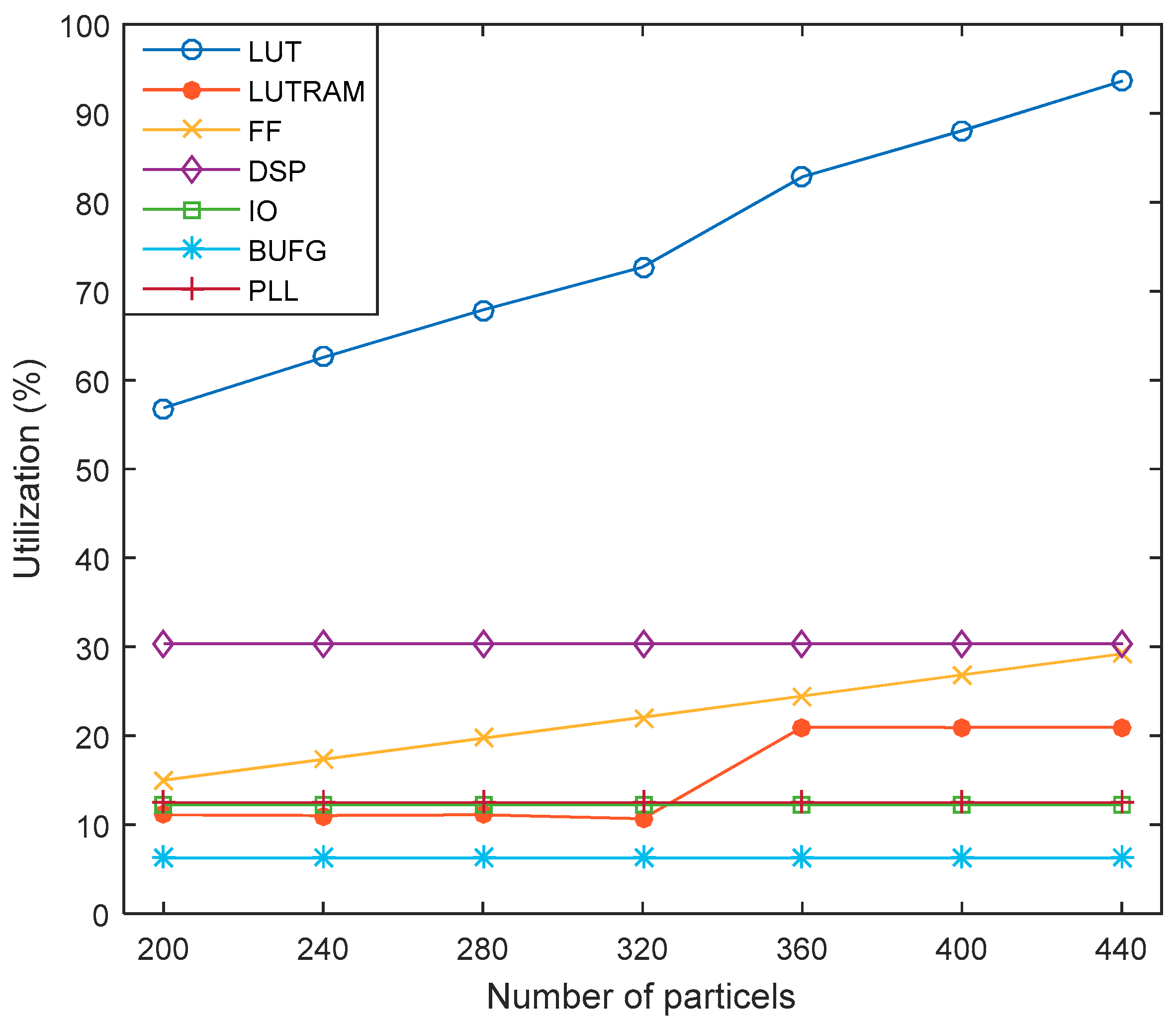
| Resource | Available | Utilization | Utilization (%) |
|---|---|---|---|
| LUT | 101,400 | 57,667 | 56.87 |
| LUTRAM | 35,000 | 3886 | 11.10 |
| FF | 2,028,000 | 30,414 | 15.00 |
| DSP | 600 | 182 | 30.33 |
| IO | 400 | 49 | 12.25 |
| BUFG | 32 | 2 | 6.25 |
| PLL | 8 | 1 | 12.50 |
| Type | Value |
|---|---|
| Total number of endpoints | 93,504 |
| The number of failing endpoints | 0 |
| Worst negative slack (WNS) | 0.33 ns |
| Total negative slack (TNS) | 0 ns |
| Worst hold slack (WHS) | 0.023 ns |
| Total hold slack (THS) | 0 ns |
| Worst pulse width slack (WPWS) | 4.788 ns |
| Total pulse width negative slack (TPWS) | 0 ns |
| Number of Particles | NBC (msg) | TBC (ms) | Optimal Throughput (msg/ms) |
|---|---|---|---|
| 200 | 10 | 8 | 1.25 |
| 240 | 10 | 8 | 1.25 |
| 280 | 10 | 8 | 1.25 |
| 320 | 10 | 8 | 1.25 |
| 360 | 10 | 8 | 1.25 |
| 400 | 10 | 8 | 1.25 |
| 440 | 10 | 8 | 1.25 |
© 2018 by the authors. Licensee MDPI, Basel, Switzerland. This article is an open access article distributed under the terms and conditions of the Creative Commons Attribution (CC BY) license (http://creativecommons.org/licenses/by/4.0/).
Share and Cite
Lee, H.; Kim, K.; Kwon, Y.; Hong, E. Real-Time Particle Swarm Optimization on FPGA for the Optimal Message-Chain Structure. Electronics 2018, 7, 274. https://doi.org/10.3390/electronics7110274
Lee H, Kim K, Kwon Y, Hong E. Real-Time Particle Swarm Optimization on FPGA for the Optimal Message-Chain Structure. Electronics. 2018; 7(11):274. https://doi.org/10.3390/electronics7110274
Chicago/Turabian StyleLee, Heoncheol, Kipyo Kim, Yongsung Kwon, and Eonpyo Hong. 2018. "Real-Time Particle Swarm Optimization on FPGA for the Optimal Message-Chain Structure" Electronics 7, no. 11: 274. https://doi.org/10.3390/electronics7110274
APA StyleLee, H., Kim, K., Kwon, Y., & Hong, E. (2018). Real-Time Particle Swarm Optimization on FPGA for the Optimal Message-Chain Structure. Electronics, 7(11), 274. https://doi.org/10.3390/electronics7110274