Article

Printed Circuit Board Drilling Machine Using Recyclables

1
Facultad de Ingeniería, Universidad del Magdalena, Santa Marta 470004, Colombia
2
Facultad de Ingeniería, Universidad Cooperativa de Colombia, Santa Marta 470003, Colombia
*
Author to whom correspondence should be addressed.
Electronics 2018, 7(10), 240; https://doi.org/10.3390/electronics7100240
Submission received: 14 September 2018 / Revised: 25 September 2018 / Accepted: 26 September 2018 / Published: 6 October 2018

Abstract

:
The implementation of a printed circuit board (PCB) drilling machine using recyclable materials and computer-aided control is presented. A mechanical system using a DC motor for movement on the X and Y axes, and a transmission mechanism by belts, pulleys, and a worm screw was made. For the Z axis, a mechanism based on a worm screw, nuts, and a stepper motor was implemented. The main board has two microcontrollers communicating in a master-slave configuration via a serial protocol. A real-time operating system (OSA) was implemented to optimize the data flow to the computer using the USB protocol, for communication with the slave microcontroller, positioning the Cartesian axes, and control the motors. The slave is responsible for monitoring the status of the encoders and limit switches, as well as the information delivery to the master. A Matlab-based user interface was developed to determine the coordinates of the holes to be drilled by processing a jpg image. This also allows the user to control the DC motors using PWM signals via configurable parameters of PID controllers. The end result is a drilling machine which able to operate both manually and via a computer, for drilling PCBs of a maximum size of 24 × 40 cm.

1. Introduction

Robotics is one of the areas of electronics that has a great influence on many of the processes with which people interact. The main purpose of this area is to build and apply intelligent systems for the execution of specific tasks, and for interaction with the real world [1]. In the field of industrial automation, robotics play a fundamental role due to technological advances that improve the efficiency of manufacturing processes. In terms of flexibility, the classification of industrial processes depends on the degree of automation and sophistication of the control systems, being less flexible than the processes of manual production, and much more robust than flexible manufacturing systems [2].
These systems are composed of machines and subsystems linked by a common transport mechanism and controller that provides the ability to perform various tasks without changing the system equipment [3]. One of the present levels in this type of system is Computer Numerical Control (CNC) technology [4]. This type of technology operation is based on the analysis of a Gerber file, which contains coordinates and instructions executed by a machine [5]. The main advantages of the implementation of CNC systems are their accuracy, reliability, and the reduction of human error. Among the disadvantages are the acquisition and maintenance costs [6,7,8]. Numerical control is used to automate machines and tools through the G-code programming language. This type of code allows the programmer to give orders to the controllers of each of the axes that make up a machine.
One of the applications of CNC technology is in the field of drilling and the manufacture of printed circuit boards (PCBs) [9], which has been studied by numerous professionals in electronics, industry, and educational centers [10]. Specifically, research has focused on developing prototypes of reliable drills with a good cost-benefit ratio. In general, these machines have a control unit and a three-axis system (X, Y, Z) that are moved by servomotors or stepper motors. The X and Y axes are used to adjust the direction of movement of the machine, while the Z axis is responsible for controlling the movement of the drill.
A PCB is a board designed to provide electrical connections between electronic components. The connections are made with thin copper traces located on the surface of the board, or in layers of copper that are interspersed with layers of insulating material. There are three types of printed circuit boards: (1) single layer, in which the copper layer is on only one side of the board; (2) two layers, in which there are two layers of copper on both sides of the board, and (3) multilayers, which consist of alternating layers of copper and insulating material. In general, multilayer boards are used to assemble complex circuits in which a large number of electronic components must be interconnected through many copper traces [11].
PCBs require a set of holes that are coated with copper, which are used as conductive paths for the electronic components. These holes can be made with chemicals or by using a drill. With the latter, cleaner and better quality holes are obtained. For this process, spiral bits are used whose diameters depend on the size of the hole to be made. A standard size is 1.27 mm, although some boards use diameters of 0.15 mm or less [11].
It is important to highlight that the use of CNC technology has allowed the industry to automate the PCB drilling process, thereby avoiding the problems that arise when this task is done manually. Drilling printed circuit boards manually can be a complicated task that needs high precision, especially when there are numerous components and the distance between holes is small.
In the literature there is various research related to the implementation of CNC machines and low-cost using embedded systems [12,13,14,15]. In [16], the authors implemented a control system for micro-drilling PCBs. In addition, research has focused on designing prototypes for manufacturing PCBs using optimization methods for the drilling process [17,18,19,20]. The authors in [21] propose a methodology to optimize the manufacturing of parts with many drilled holes.
This work is based on the construction of a prototype PCB drilling machine which applies some concepts and features of CNC technology. The prototype has a real-time operating system and a mechanical system allowing accurate movement using Cartesian coordinates. It also incorporates a computer program with an image-processing algorithm which is performed in Matlab. The main novelty of this paper is the use of recyclable materials to implement a fully functional, low-cost prototype.

2. Materials and Methods

Figure 1 shows the block diagram of the system, which is composed of the graphical user interface, the control, monitoring and power stages, the motors, and the mechanical system that was implemented in each of the 3 axes of the prototype.

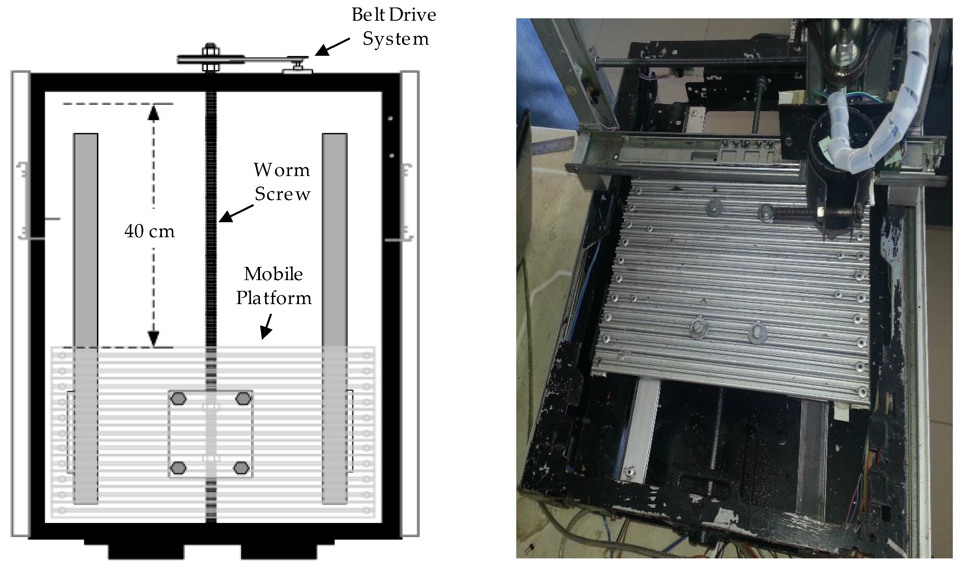
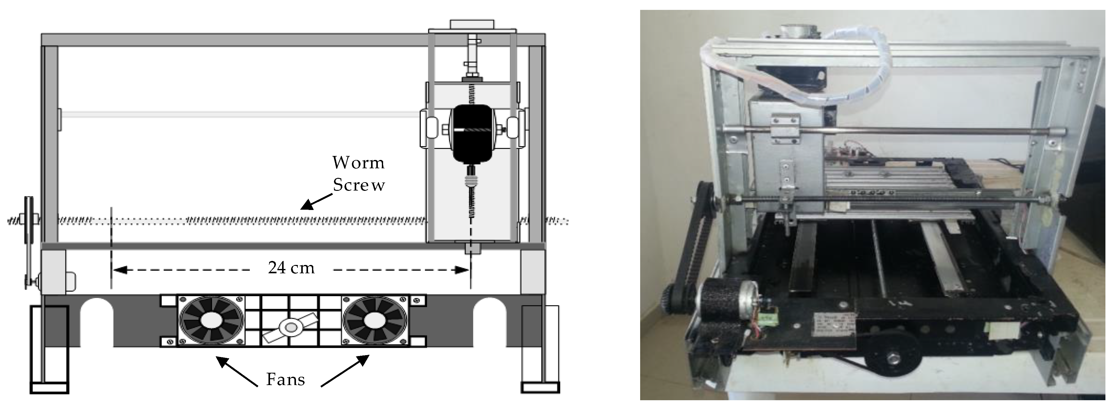
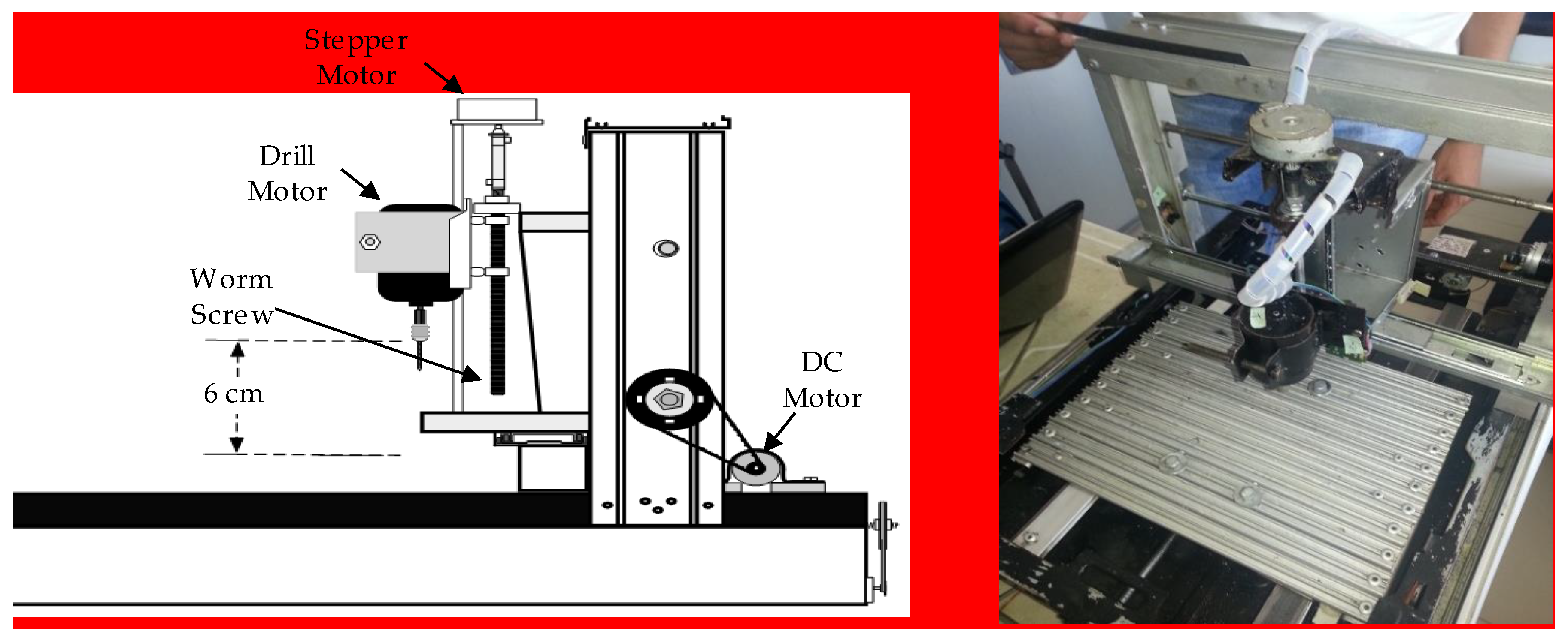
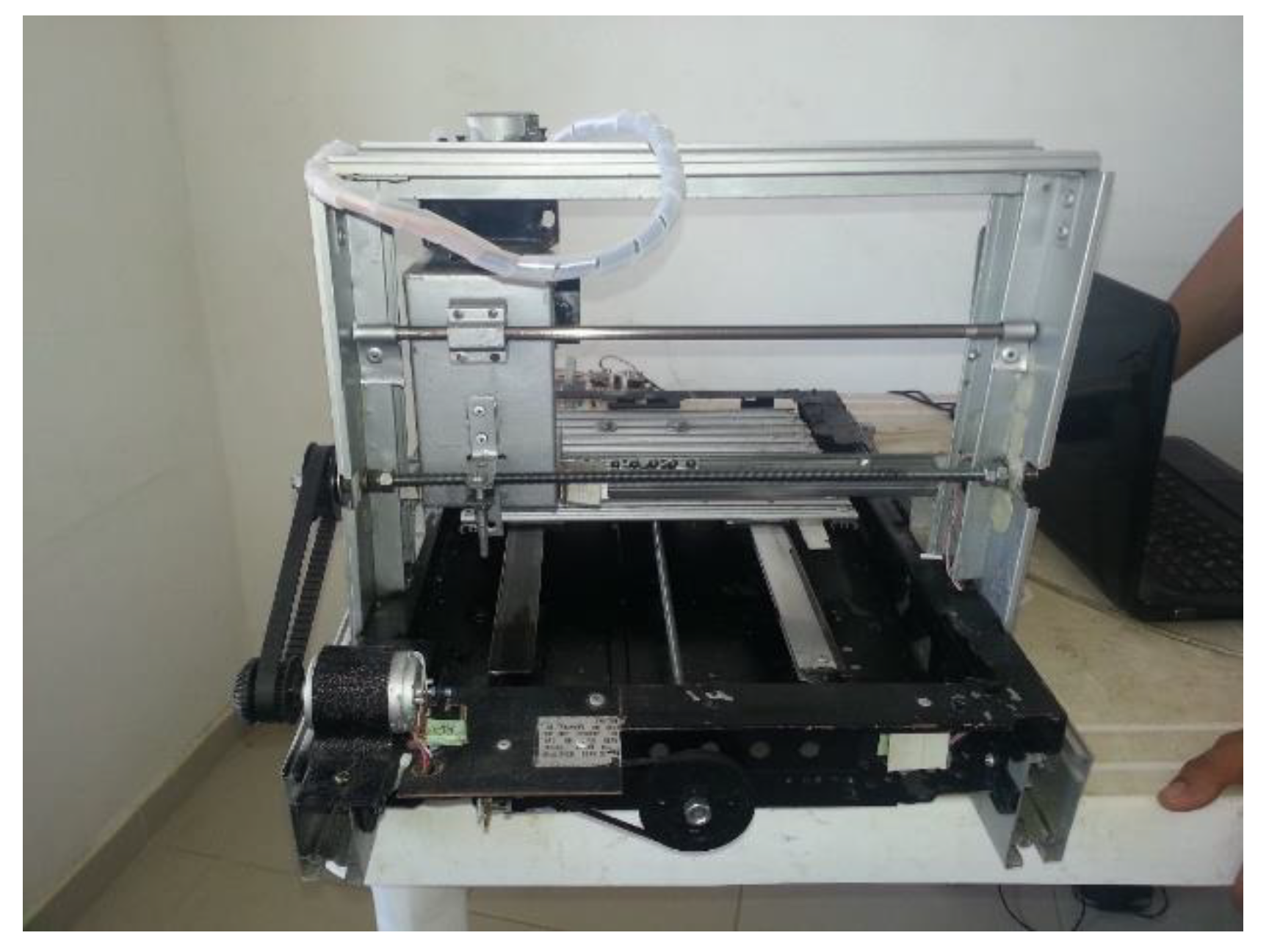
2.1. Mechanical System

For the design of the mechanical system, a metal platform extracted from a damaged copier was used. This platform was adjusted with industrial aluminum profiles and materials removed from printers and recycled aluminum furniture. In order to avoid wear resulting from transverse movement, the mechanical system with moving parts on a set of linear guides was designed. Next, is presented in detail the design process for the X, Y, Z axes.

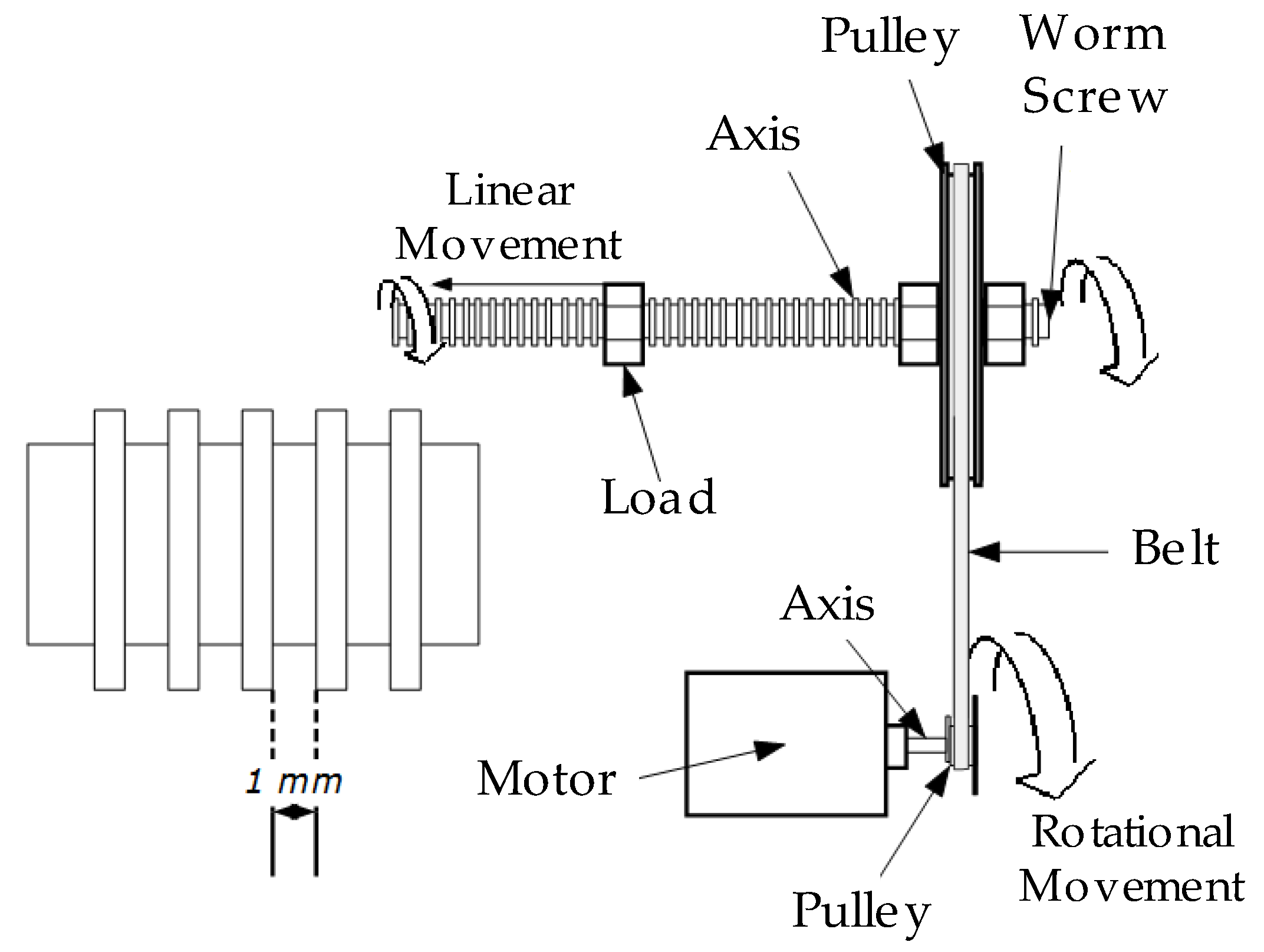
2.1.1. Belt Drive System

This element is composed of two pulleys coupled by means of a belt designed to transmit forces and angular velocities between parallel shafts that are within a certain distance. The forces are transmitted by the effect of friction exerted by the belt on the pulley. To reduce the speed and to multiply the force, the fundamental equation of speed belt transmissions applies. See Equation (1).
  ϕ 1 n 1 = ϕ 2 n 2  
where Φ1 is the diameter of the driving pulley, n1 is the rotation speed, Φ2 and n2 are the diameter and speed of the driven pulley. In this way, a transmission system for the axis Y was implemented (see Figure 2). The speed of the drive pulley is reduced by a factor of seven, and the force is multiplied by the same value. For the X axis, the same mechanism was used, but with a reduction factor of speed of 3/5.
The mechanism of belt drive operation is based on transmit power and speed to the driven shaft, which is a worm screw or millimetric rod, where the distance or pitch is defined by the spacing of the teeth, in this case is a value of 1 mm. See Figure 3.

2.1.2. Mechanical System for X, Y and Z Axes

For the Y axis, a system with a worm screw which carries an aluminum plate through support smooth longitudinal guides was designed. Displacement occurs when the motor rotates and the rotation is transmitted to the worm screw. The accuracy and smoothness of the linear movement depend largely on the progress of the smooth linear guides, and that of the nut on the screw. Thus, a maximum displacement of 40 cm is achieved on the Y axis. See Figure 4.
The mechanism of the X axis is similar to the Y axis mechanism; the difference is in the two guide rails used, which were obtained from a printer and recycled office furniture. Thus, a maximum displacement of 40 cm was obtained. (See Figure 5). With the vertical mechanism, the drill moves up and down. The movement is executed without losing stability thanks to a guide and a worm screw, achieving a displacement of 6 cm. See Figure 6.

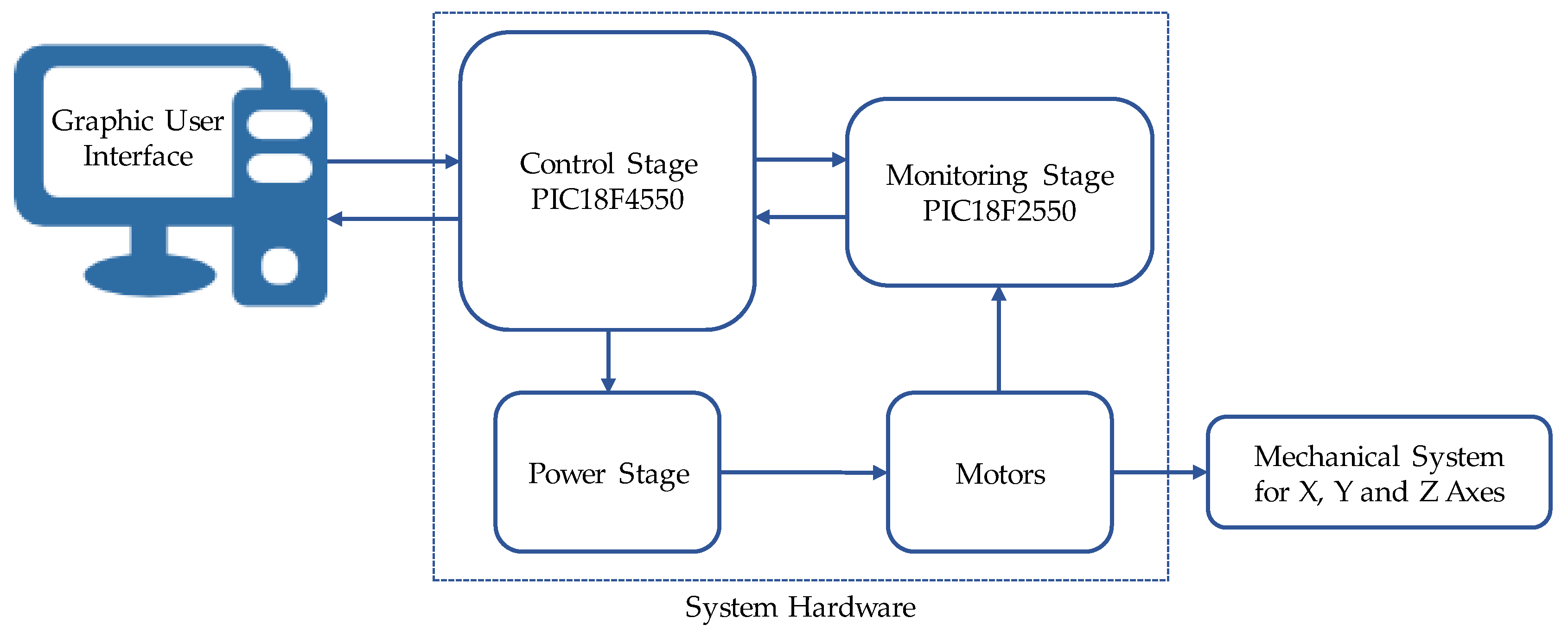
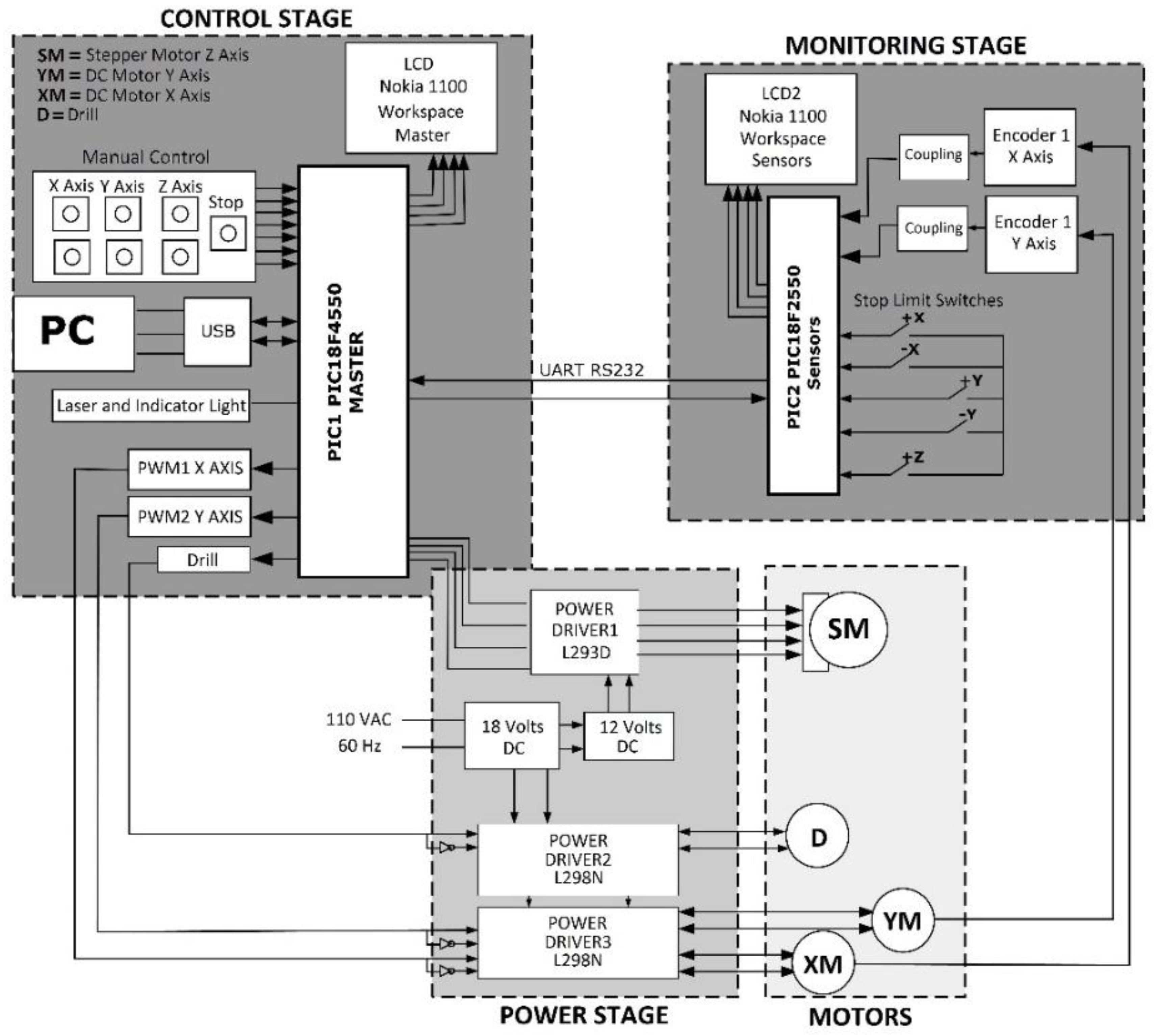
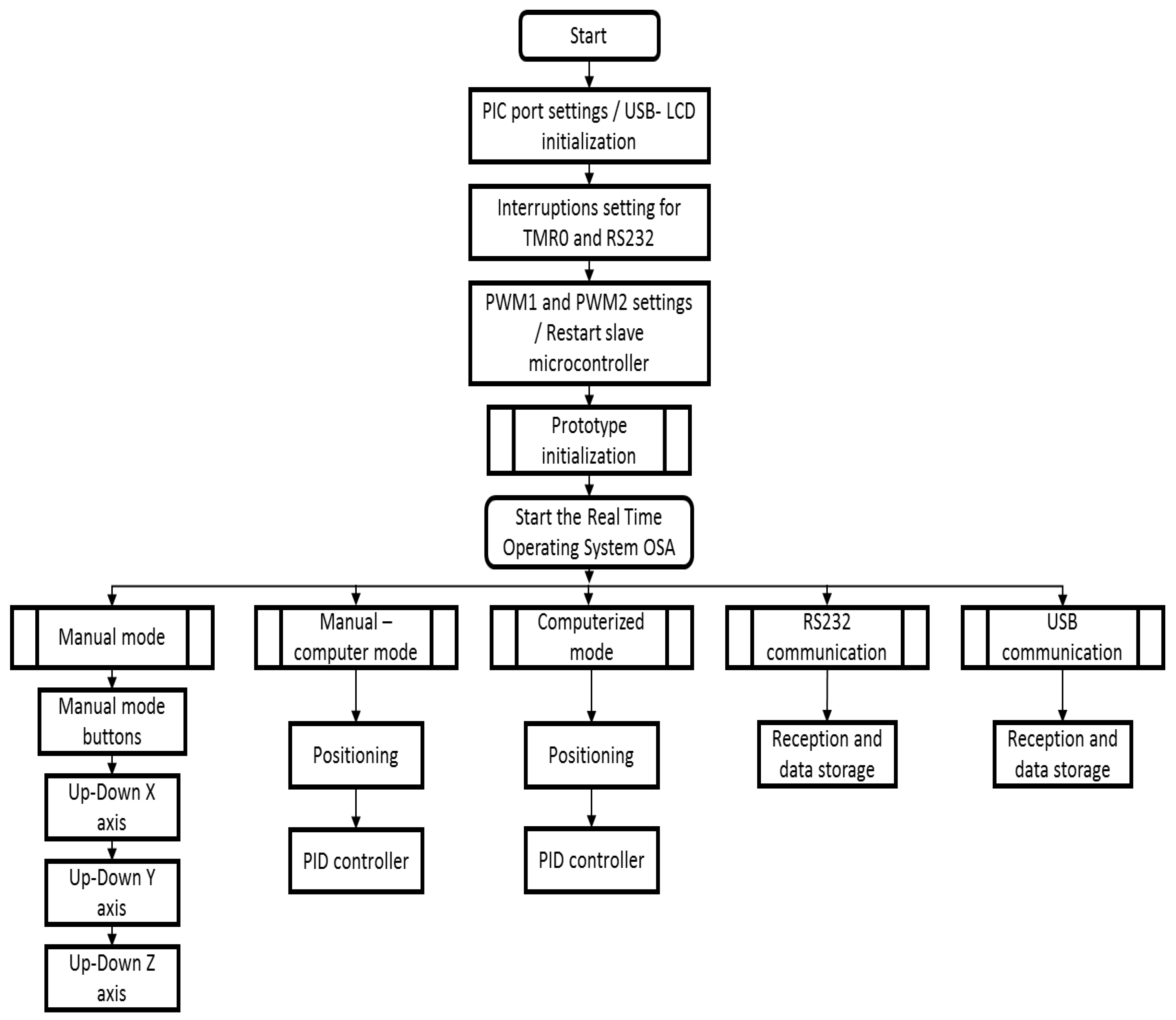
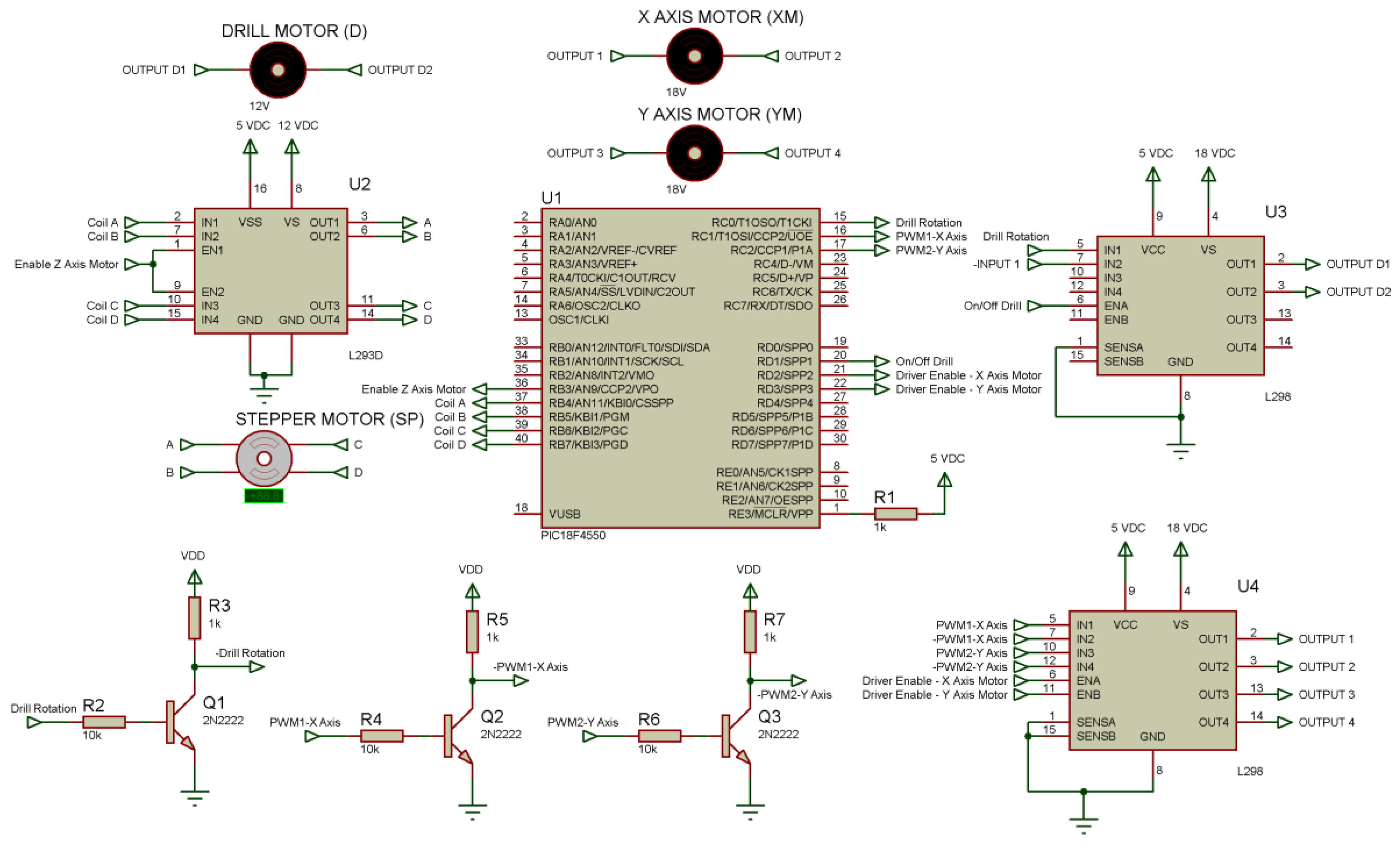
2.2. System Hardware

Figure 7 shows in detail the three main blocks: control, monitoring, and power. These stages are controlled by the master microcontroller PIC18F4550. The master is responsible for initializing the prototype and receiving the coordinates of the user interface. The coordinates are sent to the motors and, according to information from the encoders, the position is adjusted.

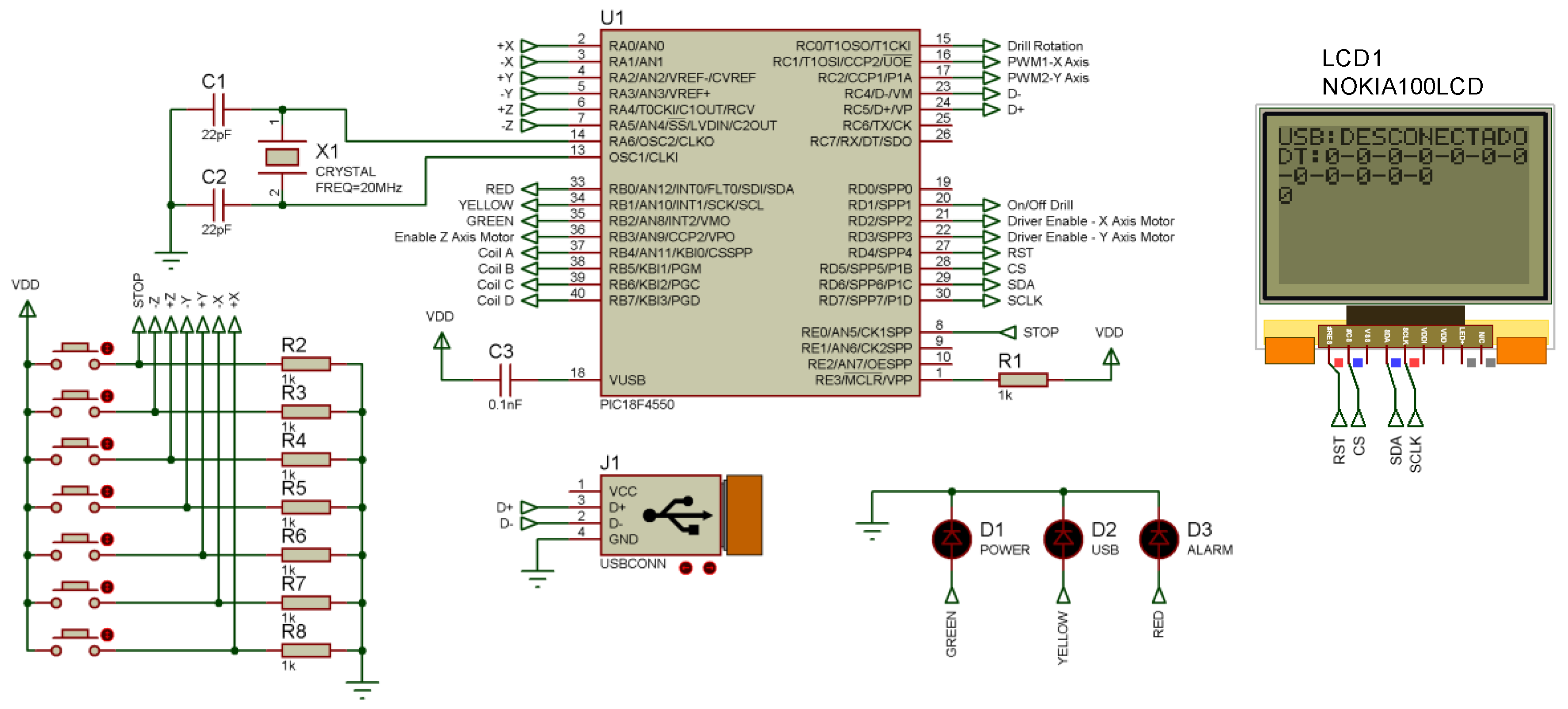
2.2.1. Control Stage

This stage is responsible for making overall control of the system, and consists of a set of blocks which are detailed below:
  • Master device: a PIC18F4550 was used as a master control device with the following functions:
    • Receiving the data sent by the user interface via the USB protocol in the mode bulk transfer.
    • Transmission and reception of data to PIC18F2550 by the Universal Asynchronous Receiver-Transmitter (UART) module.
    • Adjust the PID control for positioning of the Cartesian axes.
    • Configuration and generation of PWM signals for DC motors.
    • Initialization, verification and control of machine states.
To accomplish this, a real time operating system OSA was developed which manages the execution times of each task, thereby achieving a type of parallel processing. See Figure 8.
The PID control was tuned from the Ziegler-Nichols method; its main function is to adjust the position of the prototype, using as feedback signal the reading provided by the encoders. The error calculation is performed from the desired position and the actual position of the motor, whereby the variable actuator is modified based on Equation (2).
  PID = K p e ( t ) + K i e ( t ) dt + K d de ( t ) dt  
2.
Display: an LCD extracted from a Nokia 1100 cell recycle was used. Clock signals, data, chip select and reset were connected to the PortD of the master microcontroller, using a resistive voltage adjustment circuit to work with 3.3 V.
3.
Communication with PC: communication between the control stage and PC for operation modes manual and automatic-computerized was performed through the USB protocol. For this, it was necessary to configure the master PIC and the user interface developed in Matlab.
4.
Serial connection: for communication with the monitoring stage, the UART modules incorporated in the PIC18F4550 and PIC18F2550 microcontrollers were used. An asynchronous serial connection using the Tx and Rx pins was implemented.
5.
Control of DC motors for axes X, Y, and Drill: to control the rotation and switching on and off of each DC motor, the master microcontroller PWM module through the pin RC0, RC1 and RC3 was used.
6.
Stepper motor for the Z axis: to control the bipolar stepper permanent magnet motor, four pins of PortB to handle four reels were used. In addition, a fifth pin was used as an enabler.
7.
Manual operation: seven buttons connected to PortA master PIC to operate manually the drilling machine were used. Six buttons were used to adjust the coordinates X, Y, Z, while the remaining button is used as stop.
8.
Leds: a set of led indicators were incorporated so that the user can verify system alarms, status USB port connection, and correct polarization of the microcontroller.
Figure 9 shows the schematic diagram of the control stage, in which the established connections can be observed.

2.2.2. Monitoring Stage

This stage is controlled by the PIC18F2550 [22], which is responsible for monitoring the signals conditioned in the encoders, the state of limit switches for each axis, and displaying the information on a Nokia 1100 LCD. The information gathered by the sensors is sent to the master PIC through RS232 protocol.
Limit switches are seven PC817 optical sensors, which internally consist of a led diode and a transistor. When the transistor does not receive a lit led diode, the collector-emitter junction generates a logic 1; at the time that the collector-emitter junction receives light, it closes the circuit and generates a logical 0.
To perform the position control of the motors, CNY70 encoders measure the linear displacement of the machine. An LM324 operational amplifier was used for voltage comparisons for a coupling circuit. Figure 10 shows the schematic diagram of the monitoring stage.

2.2.3. Power Stage

This is composed of drivers that convert the logical level of 5 V at voltages of 18 V and 12 V which are needed to handle DC motors and stepper motor. The circuit has an on/off switch that can control the start and the stop of the system. The prototype handles 3 bidirectional DC motors for the drill, X and Y axes, and a stepper motor of sequential control using pulse frequency. L298 and L293 power drivers were used for motors. Figure 11 shows the schematic diagram of the power stage.

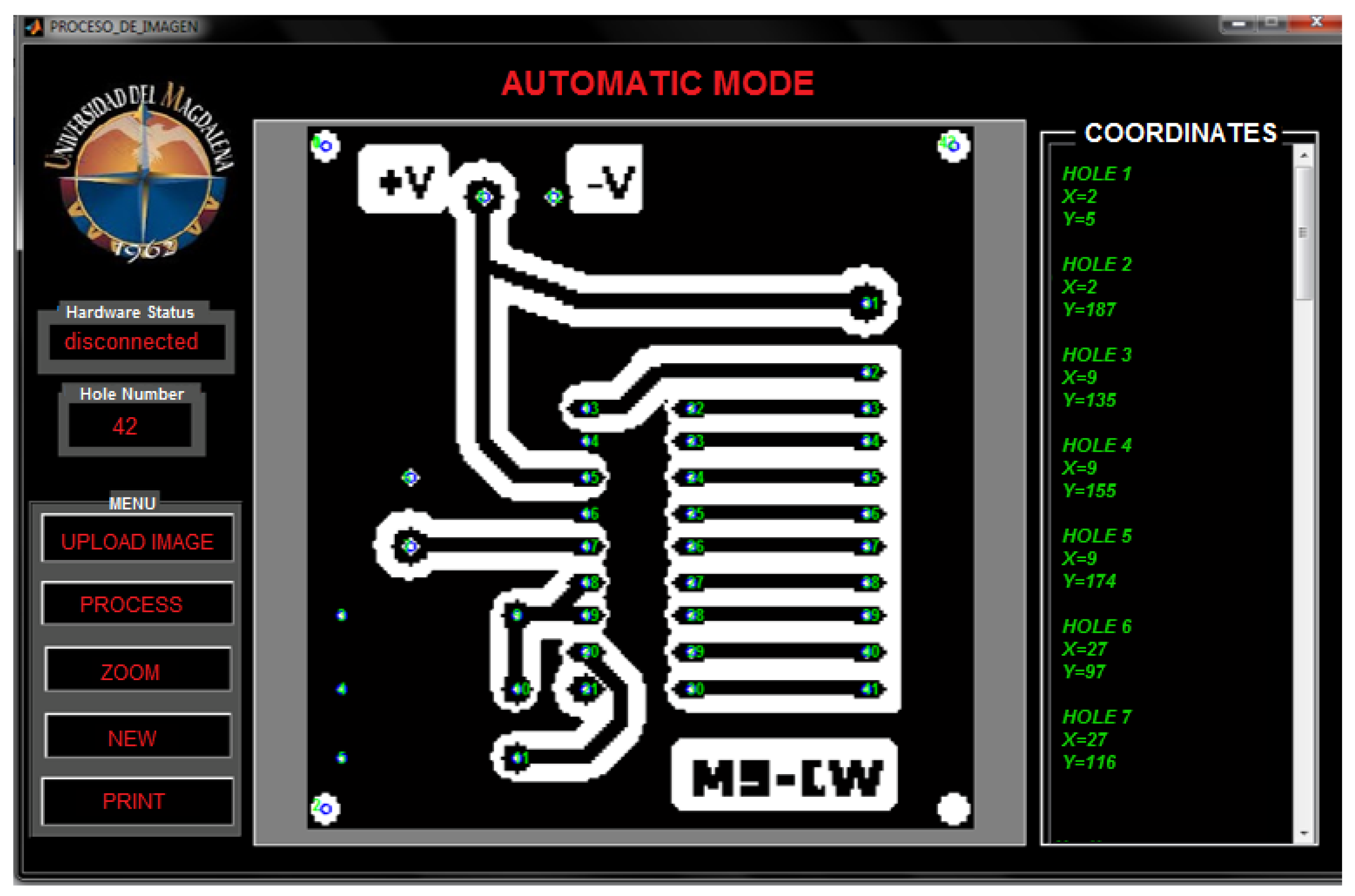
2.3. Graphic User Interface

Matlab was used to develop a graphical interface that allows the user to operate the machine in the two operating modes: manual and automatic. The interface is initially responsible for importing the image of PCB in jpg or png format, converting it to grayscale, getting the lighting levels, and finally, converting it to a matrix of zeros and ones.
Subsequently, the regionprops command is used to perform morphological image processing, whereby the area, the centroid, and the list of image pixels is obtained. Finally, an algorithm that identifies the coordinates of the drilled was performed. In Figure 12, the user interface for automatic operation mode is displayed.

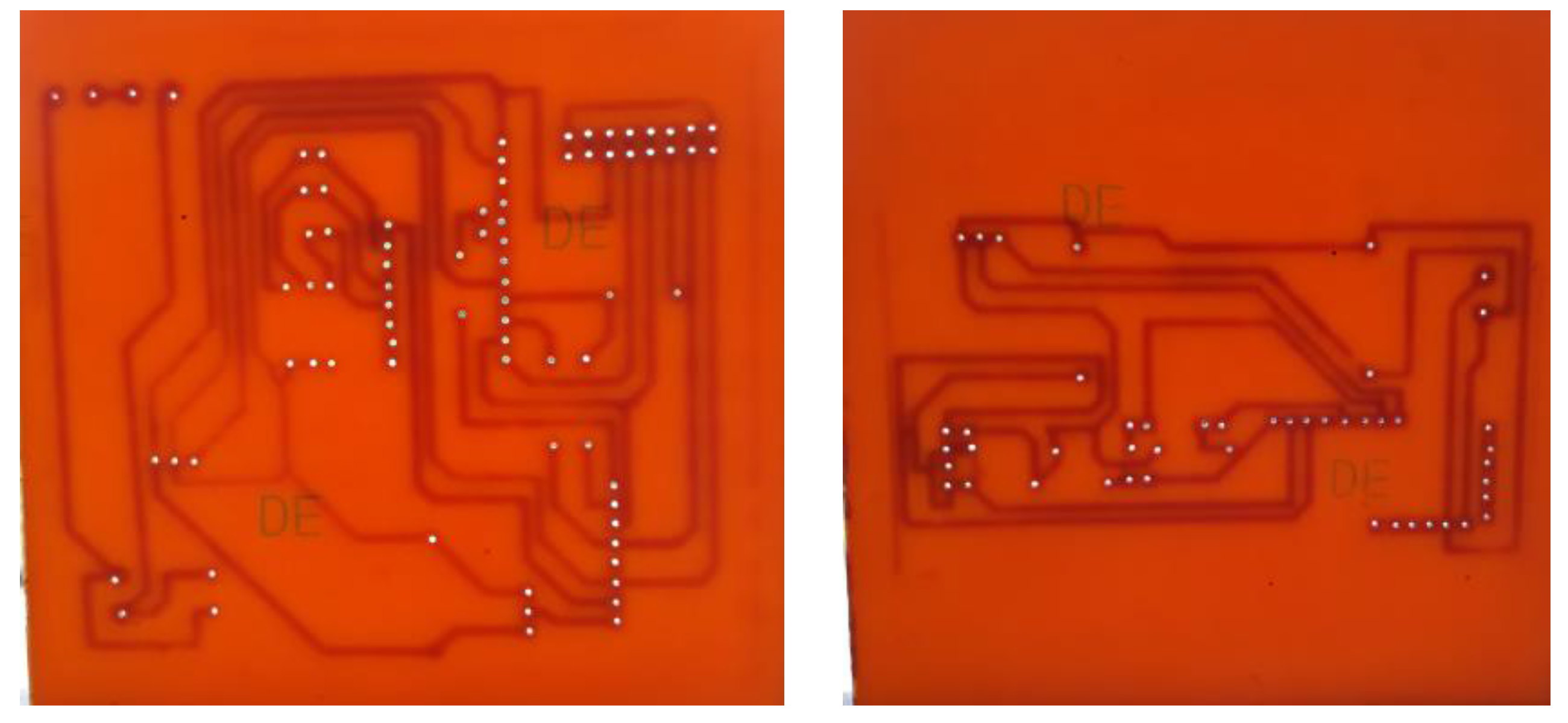
3. Results and Discussion

When performing the integration of mechanical systems for each of the X, Y, and Z axes, the implementation of the designed hardware and the completion of each programming microcontroller routine are obtained as the final result of the prototype of the drilling machine. See Figure 13.
The prototype can drill PCB with maximum dimensions of 24 × 40 cm, for a minimum distance of holes of 0.01 mm in the X axis and 0.001 mm in the Y axis. In manual and automatic operation modes, tests were performed on a total of 20 PCBs, for which successful results were achieved in 19 PCBs of different sizes and designs. The problem occurred in the process of drilling the first PCB of 15 × 24 cm, due to a failure of the optical sensor installed on the Z axis. This generated an over-displacement that affected the accuracy of the machine, which was solved by replacing the sensor.
The drilling results were as expected for a minimum drill size of 0.64 mm and a maximum size of 2.03 mm. For the tests, spiral bits with diameters of 0.5, 0.6, 0.7, 0.8 and 1 mm were used. To make the holes, a bidirectional DC motor of 18 VDC, 12,000 rpm and 1 A was used. Figure 14 shows the results obtained for two PCBs of approximately 20 × 20 cm.
During the development of the tests the displacements limits of the sensors were set at each of the ends of the X and Y axes, which respond to a distance of about 1 cm separation between the drilling head and the base of the prototype. The sensor on the Z axis avoided over-displacement problems that can cause mismatches or breakages of the screw-motor coupling.
Two PWM signals, each with a frequency of 19 KHz and a resolution of 10 bits, were generated in order to control the DC motors in the X and Y axes. With a duty cycle of 0, maximum motor speed is achieved. To stop the motors, a duty cycle of 50% was used. With a duty cycle of 100%, motors rotate at maximum speed, but in the opposite direction to the duty cycle of 0%.
With encoders, transforming the angular movement of the DC motors in a series of digital pulses was achieved; these were used for different linear displacements. Table 1 shows the relationship between the number of pulses obtained with the displacement in X and Y axes.
From the displacement data, the PID controller was designed based on the error signal that occurs between the desired position of the motor and the actual position obtained from the signals of the encoders. A half-step method was used to set the z-axis stepper motor. Thus, movements of high precision according to the design requirements were achieved.
An efficient control of the position of the drilling machine with excellent settling times was obtained, using a variable PWM control with adjustable parameters for proportional, integral, and derivative constants.
The results obtained show that a functional prototype was implemented, which has as advantages its low cost, a user-friendly interface, and an ideal working area to implement PCBs in academic projects. These characteristics are similar to those incorporated in some 3 axis commercial mini CNC drilling machines. In this category, the CNC 2417, CNC 3018, and CNC 3040T machines stand out, which have working areas of 24 × 17 cm, 30 × 18 cm, and 27.5 × 38.5 cm respectively. These machines have as disadvantages their commercial costs of between 600 and 700 USD in Colombia.
It is important to note that the prototype was developed for use in the academy by the students of the Magma Ingeniería research group of the Electronic Engineering program of Universidad del Magdalena. Therefore, the working area of the machine has limitations, i.e., its use on PCBs of industrial applications.
Additionally, the implemented prototype has limitations in terms of working with complex geometries such as integrally.bladed rotors that are used in the turbomachinery area of the aeronautical sector [23]. In these applications, it is necessary to use machines with 5 axes, which have the advantage of precision and excellent machining times [24].

4. Conclusions

A new approach has been proposed for the implementation of a drilling machine for PCB using materials in large measure from photocopiers, cell phones, printers, and recycled furniture aluminum. The prototype has functional motors, sensors, and a graphical interface made in Matlab that allow the user to monitor all procedures efficiently. For the design of the mechanical structure, industrial profiles aluminum is mainly used for its resistance to bending and twisting. The system was designed with the moving parts on a set of linear guides in order to avoid unnecessary wear following from transverse movement. Finally, it was possible to optimize the execution time with the implementation of a RTOS that allowed us to execute each of the tasks of the master microcontroller in a cooperative multitasking manner, with the assignment of a planner which is responsible for allocating the processor of the task to be executed at each instant of time.

Author Contributions

C.R.-A. conceived and supported the RTOS programming. W.E. designed the mechanical system and programmed the microcontrollers. A.P. performed the analysis of the data and wrote the paper. All authors reviewed the manuscript.

Acknowledgments

This work was supported by the Vicerrectoría de Investigación of the Universidad del Magdalena.

Conflicts of Interest

The authors declare no conflict of interest.

References

  1. Lai, C.Y.; Chavez, D.E.V.; Ding, S. Transformable parallel-serial manipulator for robotic machining. Int. J. Adv. Manuf. Technol. 2018, 97, 2987–2996. [Google Scholar] [CrossRef]
  2. Hsieh, F.S. Design of scalable agent-based reconfigurable manufacturing systems with Petri nets. Int. J. Comput. Integr. Manuf. 2018, 31, 748–759. [Google Scholar] [CrossRef]
  3. Alhama Blanco, P.J.; Abu-Dakka, F.J.; Abderrahim, M. Practical use of robot manipulators as intelligent manufacturing systems. Sensors 2018, 18, 2877. [Google Scholar] [CrossRef] [PubMed]
  4. Lu, Y.C.; Yeh, S.S. Using the segmented iterative learning control method to generate volumetric error-compensated part programs for three-axis CNC milling machine tools. J. Manuf. Mater. Process. 2018, 2, 53. [Google Scholar] [CrossRef]
  5. Moreno-Báez, A.; Miramontes-De León, G.; García-Domínguez, E.; Sifuentes-Gallardo, C. Processing Gerber files for manufacturing printed circuit boards. Procedia Eng. 2012, 35, 240–244. [Google Scholar] [CrossRef]
  6. Yemelyanov, N.V.; Yemelyanova, I.V.; Zubenko, V.L. Improving machining accuracy of cnc machines with innovative design methods. In Proceedings of the International Conference on Mechanical Engineering, Automation and Control Systems 2017, Tomsk, Russia, 4–6 December 2017. [Google Scholar]
  7. Yusof, Y.; Latif, K. New interpretation module for open architecture control based CNC systems. Procedia CIRP 2015, 26, 729–734. [Google Scholar] [CrossRef]
  8. Latif, K.; Yusof, Y.; Nassehi, A.; Alias Imran Latif, Q.B. Development of a feature-based open soft-CNC system. Int. J. Adv. Manuf. Technol. 2017, 89, 1013–1024. [Google Scholar] [CrossRef]
  9. Correa, J.E.; Toombs, N.; Ferreira, P.M. A modular-architecture controller for CNC systems based on open-source electronics. JMSY 2017, 44, 317–323. [Google Scholar] [CrossRef]
  10. Alonso, D.; Gil, J.; Martínez, F. Prototipo de máquina fresadora CNC para circuitos impresos. Revista Tekhnê 2015, 12, 23–28. [Google Scholar]
  11. Groover, M.P. Fundamentals of Modern Manufacturing, 6th ed.; John Wiley & Sons: Hoboken, NJ, USA, 2015; pp. 764–780. [Google Scholar]
  12. Desai, D.P.; Patel, D.M. Design of Control unit for CNC machine tool using Arduino based embedded system. In Proceedings of the 2015 International Conference on Smart Technologies and Management for Computing, Communication, Controls, Energy and Materials, Chennai, India, 6–8 May 2015; pp. 443–448. [Google Scholar]
  13. Basanta-Val, P.; García-Valls, M. A library for developing real-time and embedded applications in C. J. Syst. Archit. 2015, 61, 239–255. [Google Scholar] [CrossRef] [Green Version]
  14. Hou, M.; Faddis, T.N. Automatic tool path generation of a feature-based CAD/CAPP/CAM integrated system. Int. J. Comput. Integr. Manuf. 2006, 19, 350–358. [Google Scholar] [CrossRef]
  15. De Santiago-Perez, J.J.; Osornio-Rios, R.A.; Romero-Troncoso, R.J.; Cabal-Yepez, E.; Guevara-Gonzalez, R.G. Feedrate optimization by polynomial interpolation for CNC machines based on a reconfigurable FPGA controller. JSIR 2010, 69, 342–349. [Google Scholar]
  16. Bhandari, B.; Hong, Y.S.; Yoon, H.S.; Moon, J.S.; Pham, M.Q.; Lee, G.B.; Huang, Y.; Linke, B.S.; Dornfeld, D.A.; Ahn, S.H. Development of a micro-drilling burr-control chart for PCB drilling. Precis. Eng. 2014, 38, 221–229. [Google Scholar] [CrossRef]
  17. Tahir, Z.; Abu, N.A.; Sahib, S.; Herman, N.S. CNC PCB drilling machine using novel natural approach to Euclidean TSP. In Proceedings of the 2010 3rd International Conference on Computer Science and Information Technology, Chengdu, China, 9–11 July 2010; pp. 481–485. [Google Scholar]
  18. Huang, X.; Chen, Z.S.; Wang, C.Y.; Zheng, L.J.; Song, Y.X. Measurement of micro-drill breakage during PCB drilling. Mater. Sci. Forum 2016, 836, 592–599. [Google Scholar] [CrossRef]
  19. Yoon, H.S.; Moon, J.S.; Pham, M.Q.; Lee, G.B.; Ahn, S.H. Control of machining parameters for energy and cost savings in micro-scale drilling of PCBs. J. Clean. Prod. 2013, 54, 41–48. [Google Scholar] [CrossRef]
  20. Borkar, B.R.; Puri, Y.M.; Kuthe, A.M.; Deshpande, P.S. Automatic CNC Part Programming for through Hole Drilling. Procedia Mater. Sci. 2014, 5, 2513–2521. [Google Scholar] [CrossRef]
  21. Ioan, M.; Razvan, C. Drill hole sets manufacturing on CNC machines. Procedia Technol. 2015, 19, 135–140. [Google Scholar] [CrossRef]
  22. Polo, A.; Narvaez, P.; Robles Algarín, C. Implementation of a cost-effective didactic prototype for the acquisition of biomedical signals. Electronics 2018, 7, 77. [Google Scholar] [CrossRef]
  23. González, H.; Calleja, A.; Pereira, O.; Ortega, N.; López de Lacalle, L.N.; Barton, M. Super abrasive machining of integral rotary components using grinding flank tools. Metals 2018, 8, 24. [Google Scholar] [CrossRef]
  24. López De Lacalle, L.N.; Lamikiz, A.; Ocerin, O.; Díez, D.; Maidagan, E. The Denavit and Hartenberg approach applied to evaluate the consequences in the tool tip position of geometrical errors in five-axis milling centres. Int. J. Adv. Manuf. Technol. 2008, 37, 122–139. [Google Scholar]
Figure 1. Block diagram of the system.
Electronics 07 00240 g001
Figure 2. Transmission system for the Y axis.
Electronics 07 00240 g002
Figure 3. Belt drive system coupled to worm screw.
Electronics 07 00240 g003
Figure 4. Mechanical system of the Y axis.
Electronics 07 00240 g004
Figure 5. Mechanical system of the X axis.
Electronics 07 00240 g005
Figure 6. Mechanical system of the Z axis.
Electronics 07 00240 g006
Figure 7. Block diagram of the prototype.
Electronics 07 00240 g007
Figure 8. Flowchart of real time operating system OSA.
Electronics 07 00240 g008
Figure 9. Schematic diagram of the control stage.
Electronics 07 00240 g009
Figure 10. Schematic diagram of the monitoring stage.
Electronics 07 00240 g010
Figure 11. Schematic diagram of the power stage.
Electronics 07 00240 g011
Figure 12. Graphic user interface in automatic mode.
Electronics 07 00240 g012
Figure 13. PCB drilling machine.
Electronics 07 00240 g013
Figure 14. Results for PCBs of 20 × 20 cm.
Electronics 07 00240 g014
Table 1. Pulse number and displacement.
Displacement (cm)X-Axis PulsesY-Axis Pulses
182257
2172527
54121329
108112628
129623170
1612844143

