Article

Experimental Investigation of Subject-Specific On-Body Radio Propagation Channels for Body-Centric Wireless Communications

1
School of Electronic Engineering and Computer Science, Queen Mary University of London, Mile End Road London, London E1 4NS, UK
2
Electronics and Telecommunication Engineering, University of Liberal Arts Bangladesh, Dhaka 1209, Bangladesh
*
Author to whom correspondence should be addressed.
Electronics 2014, 3(1), 26-42; https://doi.org/10.3390/electronics3010026
Submission received: 20 November 2013 / Revised: 17 January 2014 / Accepted: 20 January 2014 / Published: 28 January 2014
(This article belongs to the Special Issue Wearable Electronics)

Abstract

:
In this paper, subject-specific narrowband (2.45 GHz) and ultra-wideband (3–10.6 GHz) on-body radio propagation studies in wireless body area networks (WBANs) were performed by characterizing the path loss for eight different human subjects of different shapes and sizes. The body shapes and sizes of the test subjects used in this study are characterised as thin, medium build, fatty, shorter, average height and taller. Experimental investigation was made in an indoor environment using a pair of printed monopoles (for the narrowband case) and a pair of tapered slot antennas (for the ultra-wideband (UWB) case). Results demonstrated that, due to the different sizes, heights and shapes of the test subjects, the path loss exponent value varies up to maximum of 0.85 for the narrowband on-body case, whereas a maximum variation of the path loss exponent value of 1.15 is noticed for the UWB case. In addition, the subject-specific behaviour of the on-body radio propagation channels was compared between narrowband and UWB systems, and it was deduced that the on-body radio channels are subject-specific for both narrowband and UWB system cases, when the same antennas (same characteristics) are used. The effect of the human body shape and size variations on the eight different on-body radio channels is also studied for both the narrowband and UWB cases.

1. Introduction

In body-centric wireless networks, various units/sensors are scattered on/around the human body to measure specified physiological data, as in patient monitoring for healthcare applications [1]. A body-worn base station will receive the medical data measured by the sensors located on/around the human body. Body-centric wireless networks have a range of applications, from the monitoring of patients with chronic diseases and care for the elderly, to general well-being monitoring and performance evaluation in sports [2,3,4,5,6]. The human body is considered as an uninviting and even hostile environment for a wireless signal. The diffraction and scattering from body parts, in addition to the tissue losses, lead to a strong attenuation and distortion of the signal [1]. In order to design power-efficient on-body communication systems, an accurate understanding of the wave propagation, the radio channel characteristics and attenuation around the human body is extremely important. To ensure the efficient performance of wireless body area networks (WBANs), the propagation channels need to be modelled and characterised. In the past few years, researchers have been thoroughly investigating narrow band and ultra-wideband on-body radio channels. In [7,8,9,10,11,12,13,14], on-body radio channel characterisation was presented at the unlicensed frequency band of 2.45 GHz. UWB on-body radio propagation channel characterisation for body-centric wireless networks have been presented extensively in the open literature [15,16,17,18,19,20,21,22,23,24,25,26,27]. However, the sizes and shapes of the different human bodies will affect the propagation path and lead to different system performances. In [28], on-body radio channel measurement results for three different human body sizes were presented. From the subject-specific on-body radio propagation prospective, very limited work is presented in the literature [29,30] that is mostly based on the finite difference time domain (FDTD) technique. In previous studies, there was not a sufficiently thorough analysis, and the number of phantoms was limited. No experimental studies have been performed yet in the literature for subject-specific behaviour, either by using narrowband or UWB systems. However, a thorough investigation and analysis of subject-specific on-body radio propagation channels for a wider number of people with different shapes, sizes and heights both in narrowband and UWB systems are required. A comparison of the on-body radio channels subject specificity between narrowband and UWB is required in order to specify which technology is more subject-specific.
Potential narrowband and ultra-wideband (UWB) body-centric wireless networks need to provide efficient and reliable communication channels. Critical issues remain with regard to the human body effect, shapes and sizes of the body, indoor propagations and radio channel characterization, which all must be addressed before the concept can be deployed for commercial applications. In this paper, subject-specific narrowband (2.45 GHz) and ultra-wideband (3–10.6 GHz) on-body radio propagation studies in wireless body area networks (WBANs) were performed by characterising the path loss for eight different human subjects (male) of different shapes, sizes and heights. An experimental investigation was made in the indoor environment using a pair of printed monopoles (for the narrowband case) and a pair of tapered slot antennas (for the UWB case). A frequency domain measurement set up was applied for both narrowband and UWB cases. The impact of different body shapes and sizes on the on-body radio communication channel was analysed at 2.45 GHz and 3–10 GHz. In addition to this, comparison between narrowband and ultra-wideband on-body radio propagation channel subject-specificity is also discussed.
The rest of the paper is organized as follows. Section 2 illustrates measurement setup and subject-specific on-body radio channel characterization for narrowband communication. Section 3 presents measurement studies for UWB subject-specific on-body radio channel. In Section 4, a comparison is presented between narrowband and UWB subject-specific studies, and finally, Section 5 draws the conclusion of the presented work.

2. Narrowband Subject-Specific On-Body Radio Propagation Channel Characterisation
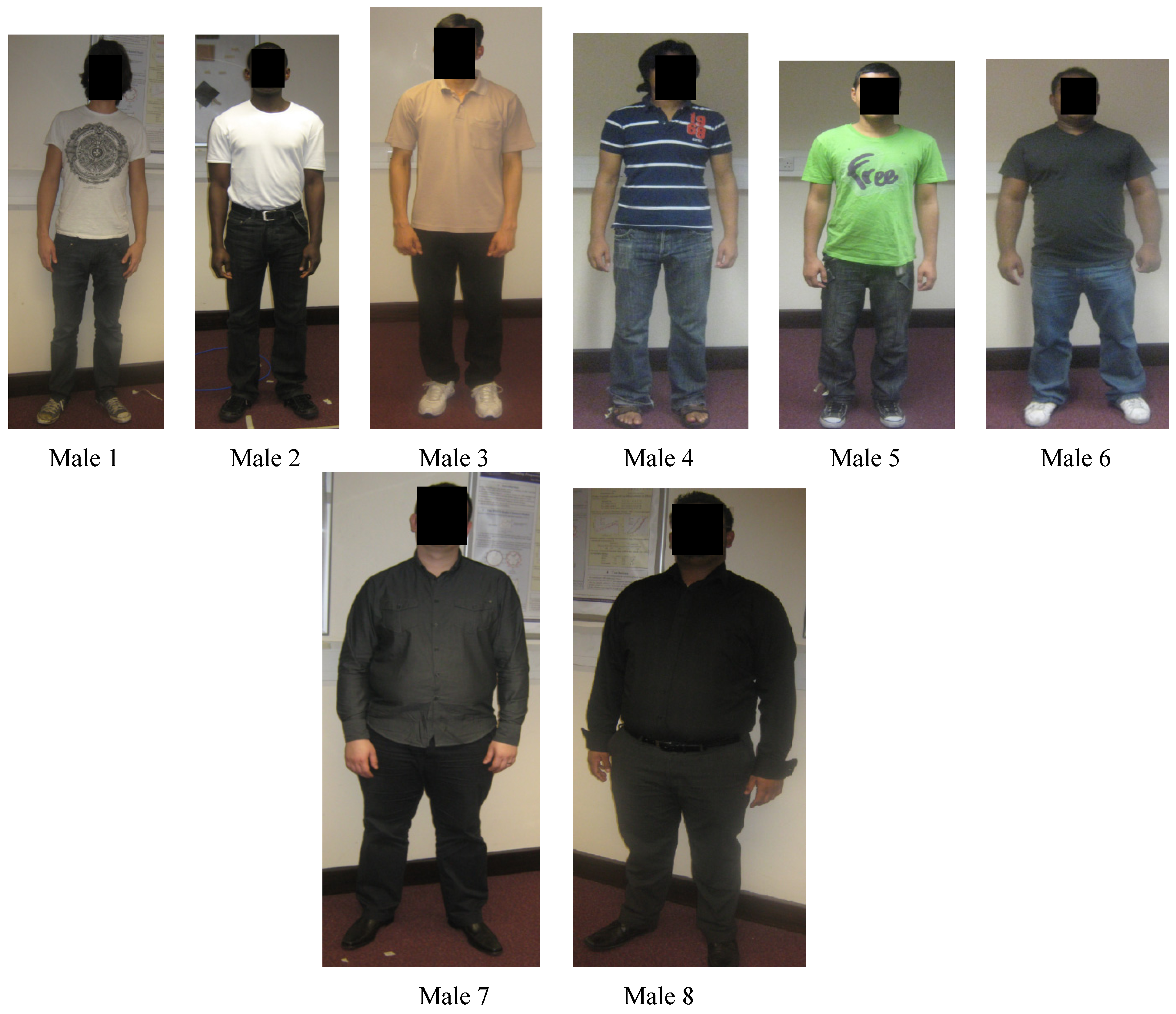
A total of eight male human test subjects were considered in this study. The heights and weights of the test subjects are listed in Table 1, together with the chest and waist circumferences. Figure 1 shows the photographs of the test subjects used in this experiment.
Figure 1. The photographs of the eight test male subjects used for on-body radio propagation channel measurement (the dimensions are shown in Table 1).
Electronics 03 00026 g001
Table 1. The dimensions of eight test subjects (male) used in this study.
DimensionsMale 1Male 2Male 3Male 4Male 5Male 6Male 7Male 8
Height (cm)182181186178169168188180
Weight (kg)707374786891120128
Chest Circumference (cm)8791929394114124136
Waist Circumference (cm)798182 868996130140

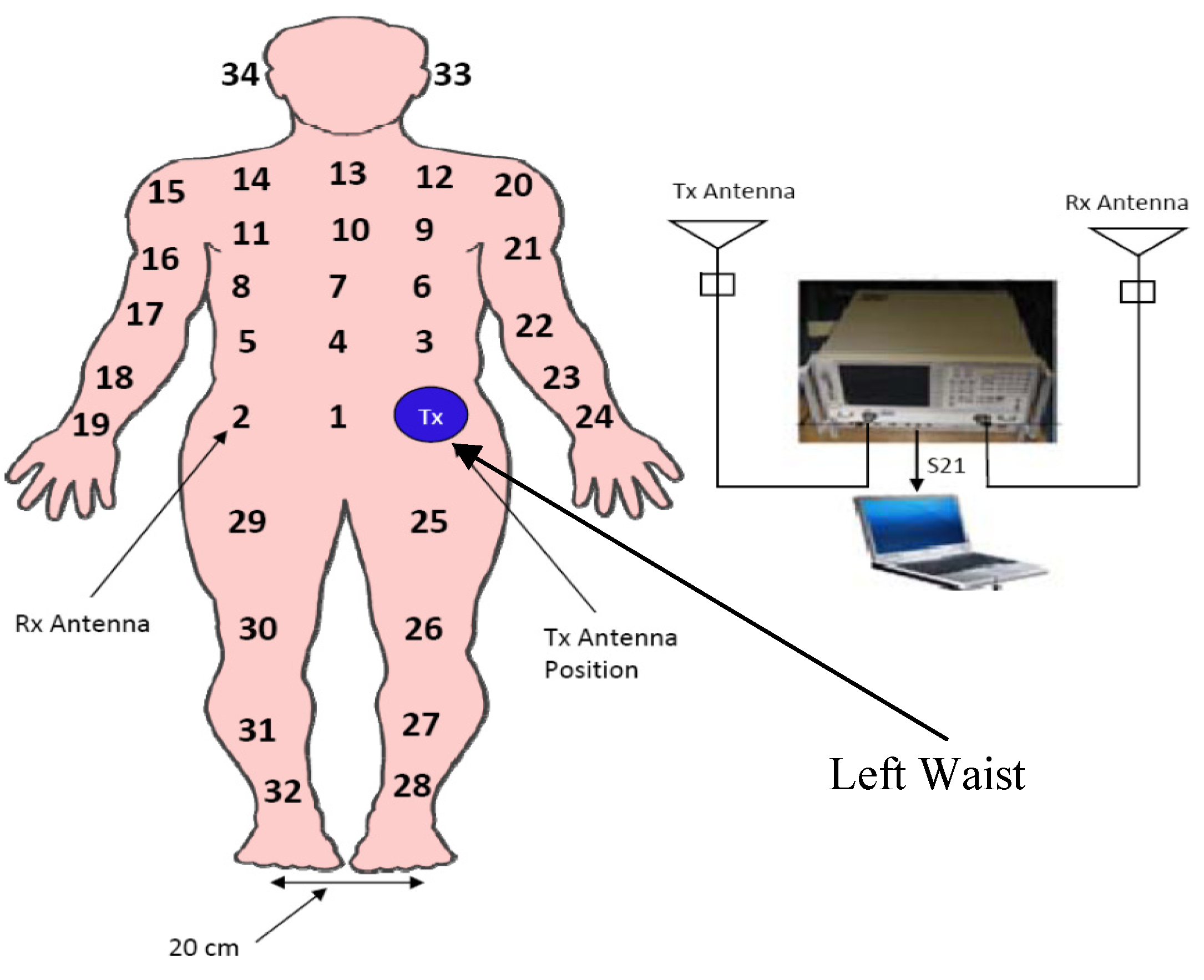
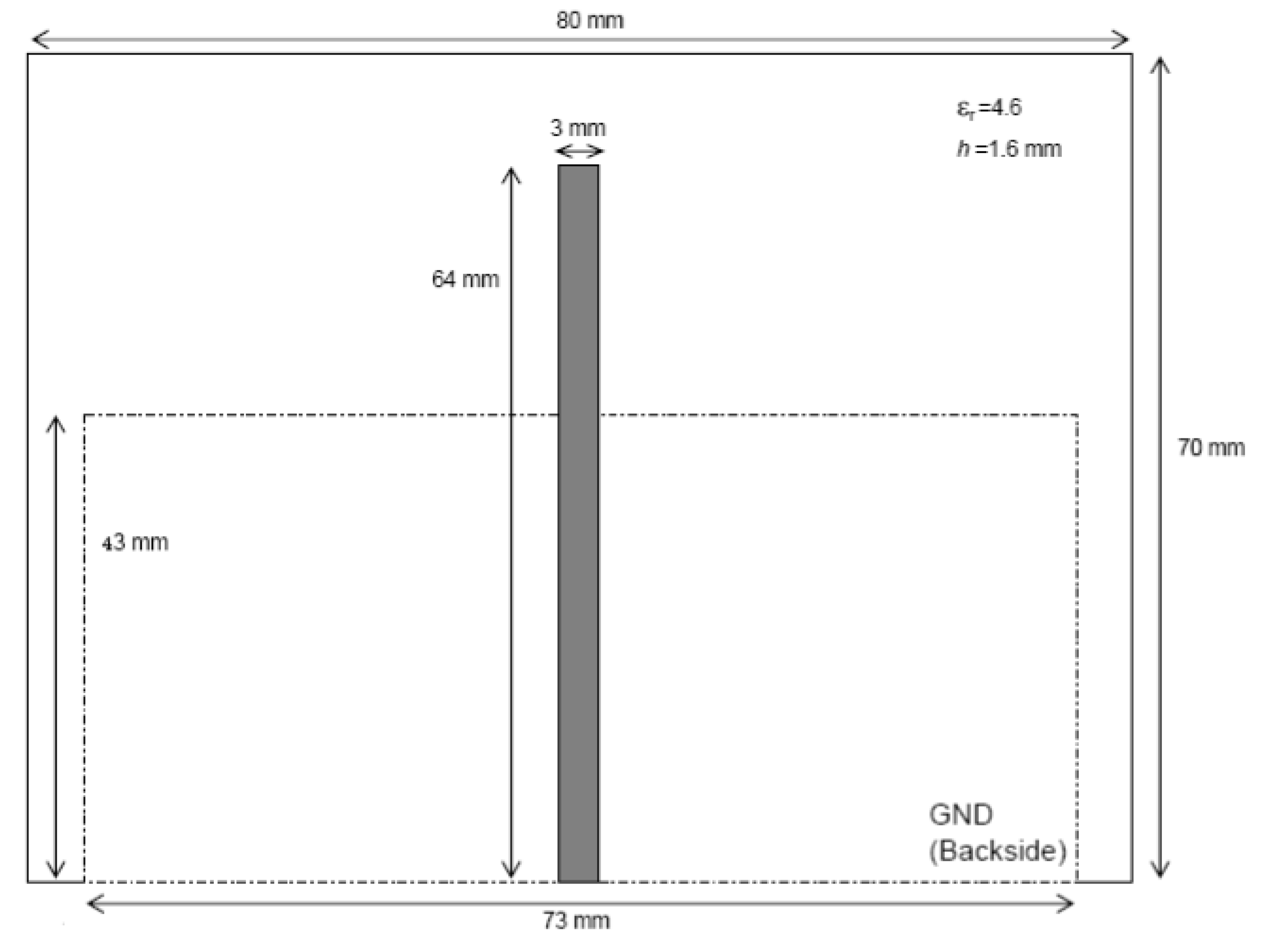
2.1. Measurement Settings

For the narrowband subject-specific on-body radio propagation channel study, a pair of printed monopole antennas (working at 2.45 GHz) were used [31], as shown in Figure 2. The radiating element of the printed monopole antenna was designed on the FR4 board with εr = 4.6 and a thickness of 1.6 mm. There is a partial ground plane at the back side of the printed monopole antenna. The radiation pattern of the printed monopole antenna becomes directive when it is placed on the human body. A HP8720ES vector network analyser (VNA) was used to measure the transmission response (S21) between two printed monopole antennas placed on the body. During the measurements, the transmitter antenna connecting with the cable was placed on the left waist, while the receiver antenna connecting with the cable was successively placed on 34 different locations on the front part of the standing human body, as shown in Figure 3. The antennas were oriented with radiating elements parallel to the body and facing outward. During the measurement, both transmitter and receiver antennas were placed on the cloths of all test subjects. The clothing was consistent between the test subjects used in this experiment. All the test subjects used in this experiment wearied a T-shirt and jeans during the measurements. The test subjects were standing still during the measurements, and for each receiver location and measurement scenario, 10 sweeps were considered. The effects of the cable were calibrated out. The measurement campaigns were performed in the Body-Centric Wireless Sensor Laboratory at Queen Mary, University of London [21].
Figure 2. Schematic diagram of the printed monopole antenna used in this study [31].
Electronics 03 00026 g002
Figure 3. On-body radio propagation measurement settings showing that the transmitter antenna is on the left waist, while the receiver antenna is on 34 different locations of the body. Rx, receiver; Tx, transmitter.
Electronics 03 00026 g003

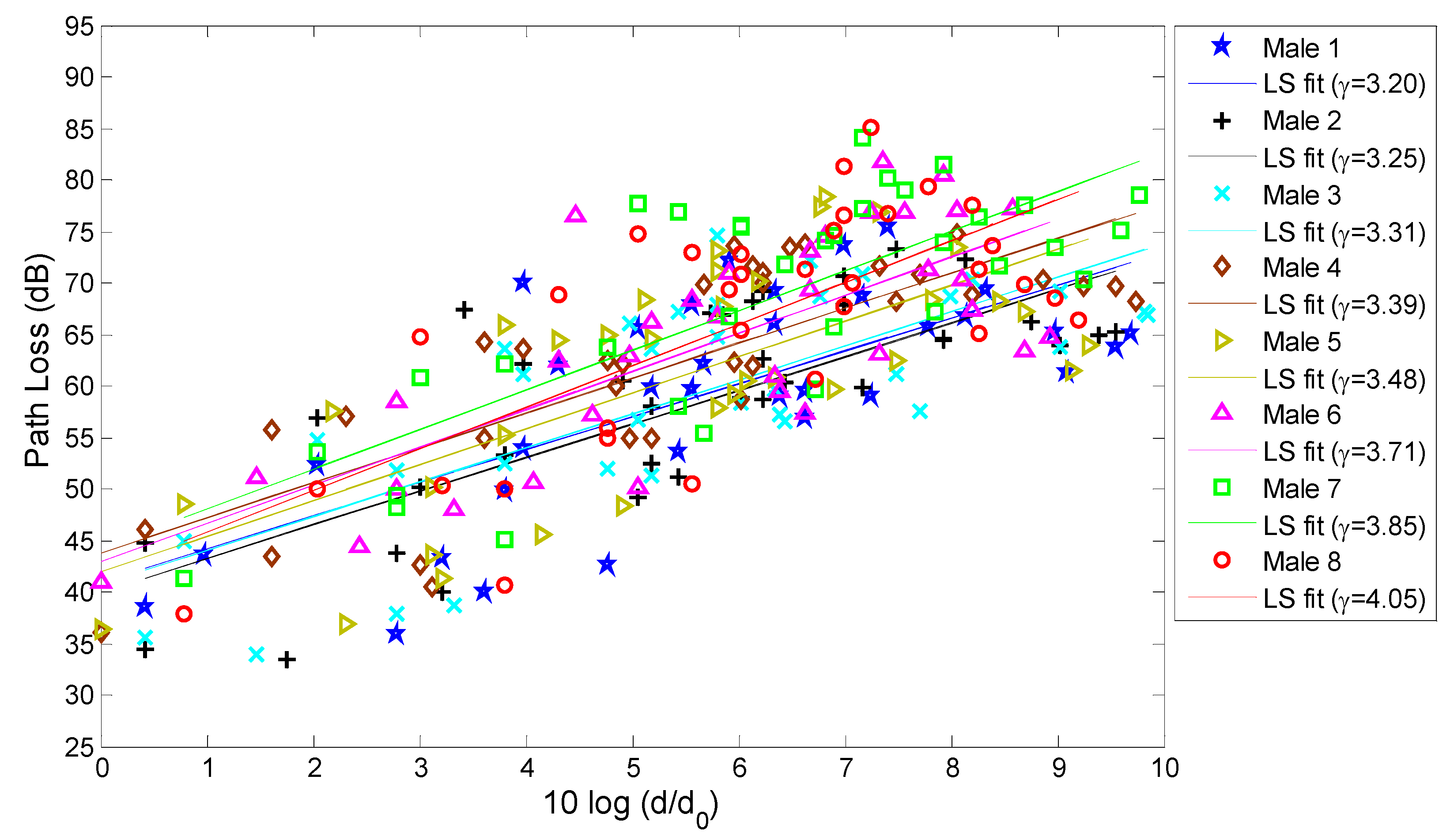
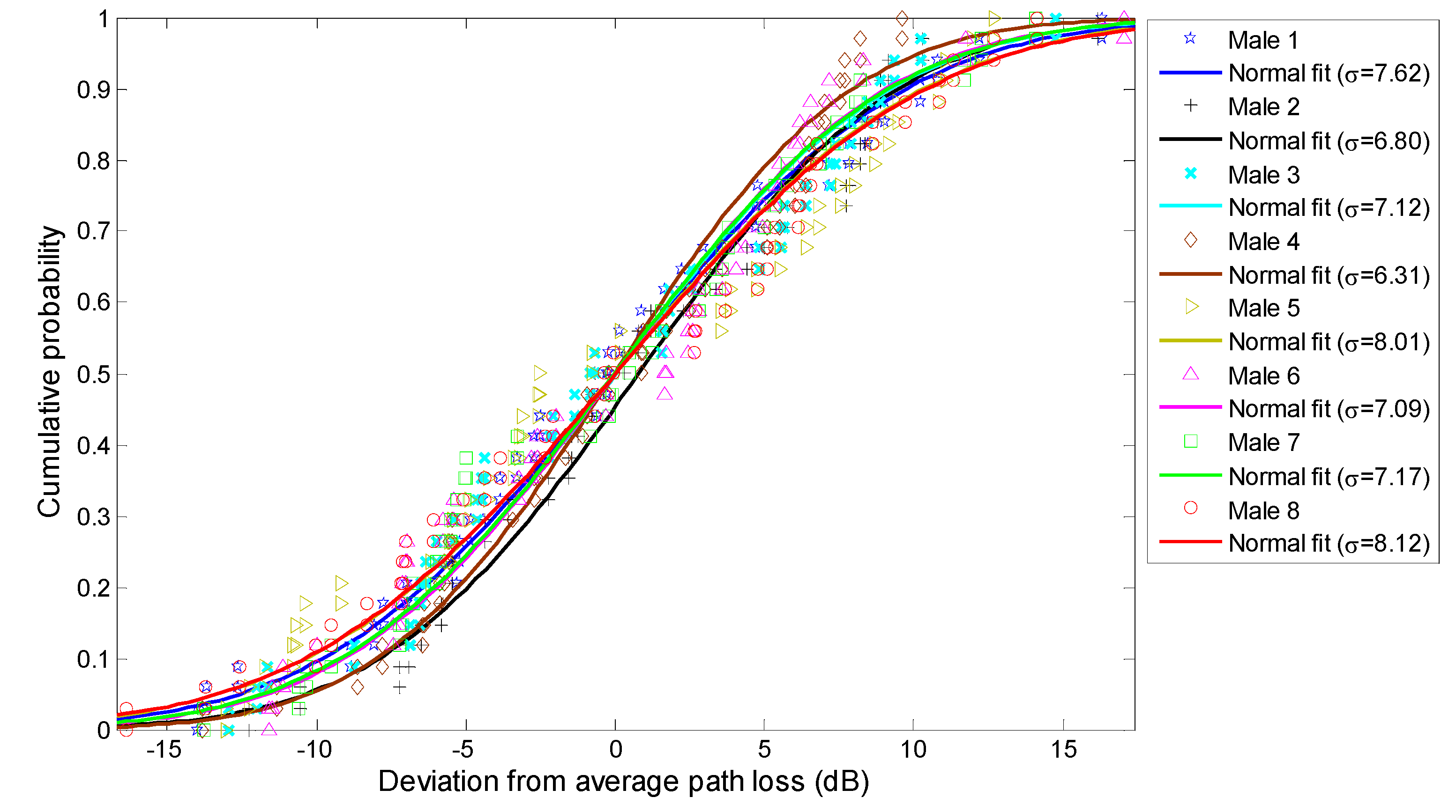
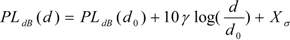
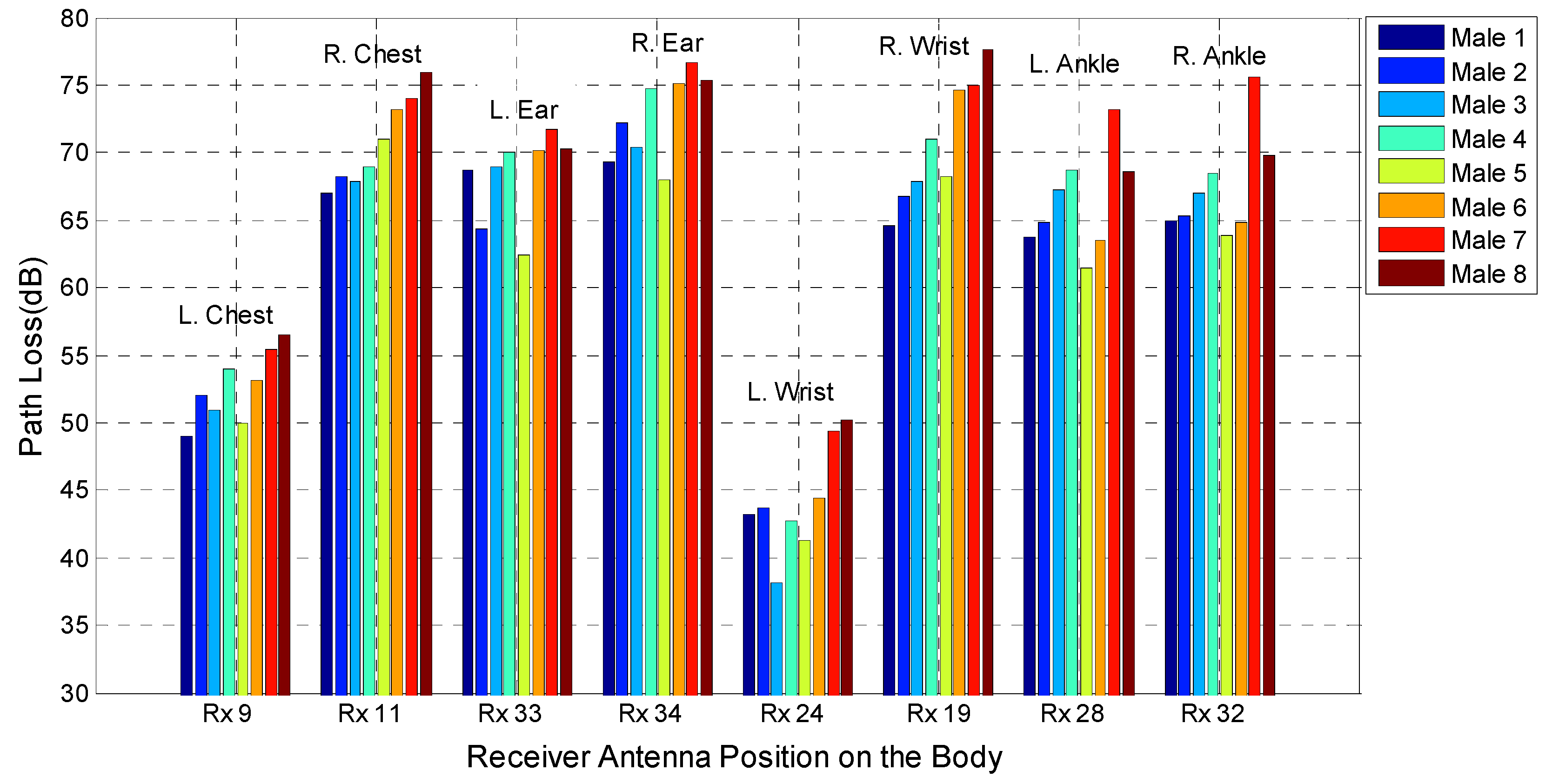
2.2. Narrowband On-Body Path Loss Characterisation

The path loss for the different receiver locations was calculated directly from the measurement data of S21 (10 sweeps) averaging at 2.45 GHz. It is well known that the average received signal decreases logarithmically with distance (for both indoor and outdoor environments). The path loss can be modelled as a linear function of the logarithmic distance between the transmitter and receiver, as explained in [32],
Electronics 03 00026 i001
where d is the distance between the transmitter and receiver, d0 is a reference distance set to a measurement (in this study, it is set to 10 cm), PLdB(d0) is the path loss value at the reference distance and Xσ is the shadowing fading. The parameter, γ, is the path loss exponent that indicates the rate at which the path loss increases with distance.
In order to model the path loss as a linear function of the logarithmic distance, a least-squares fit was performed on the measured path loss data for 34 different receiver locations, as shown in Figure 4. Table 2 lists the value of path loss exponents and path loss at the reference distance d0 obtained for the eight different test subjects. Due to the different body sizes, shapes and heights, the path loss exponent, γ, varies for the different human bodies. In this study for the narrowband case, a maximum variation in the path loss exponent of 0.85 is noticed (Male 1 and Male 8). The results show that the path loss exponent generally increases with body size.
In the case of subjects with a low value of body chest and waist circumferences, such as Male 1, Male 2 and Male 3, the path loss exponent is lower, whereas with large values of chest and waist circumferences (Male 6, Male 7 and Male 8), the path loss exponent is higher. In this case, for thinner subjects (Male 1, Male 2 and Male 3), the propagation between the Tx (transmitter) and Rx (receiver) has more line of sight (LOS) than the test subjects with a higher volume of chest and waist circumferences, resulting in lower path loss exponents (γ = 3.2, γ = 3.25 and γ = 3.31 for Male 1, Male 2 and Male 3, respectively). For the subjects with a higher radius of the curvature of the trunk, such as Male 6, Male 7 and Male 8, the wave reaches the receiver through creeping wave propagation, which has higher signal attenuation, thus leading to a higher value of the exponent (γ = 3.71, γ = 3.85 and γ = 4.05 for Male 6, Male 7 and Male 8, respectively). For the subjects with a higher volume of chest and waist circumferences, the communication for some of the receiver locations is heavily blocked by the different body parts, compared to the subject with a lower value of chest and waist circumferences. In addition, the body tissues, reflection, diffraction and scattering from the body parts are also different for various subjects, which contribute to the variation of path loss. For the on-body radio channel, the propagation is mainly through creeping wave, free space and guided wave. Different shapes and sizes of the test subjects affect the propagation mode for on-body propagation links.
Table 2. Narrowband on-body path loss parameters for the eight different test subjects. The parameter, γ, is the path loss exponent, PLdB(d0) is the path loss at the reference distance and σ is the standard deviation of the normally distributed shadowing factor.
Path Loss ParametersMale 1Male 2Male 3Male 4Male 5Male 6Male 7Male 8
γ3.203.253.313.393.483.713.854.05
PLdB(d0) (dB)41.0 40.840.743.842.042.844.241.7
σ (dB)7.626.807.126.318.017.097.178.12
Figure 4. Measured and modelled path loss for narrowband on-body channels versus the logarithmic Tx-Rx separation distance of different human test subjects (Male 1–Male 8).
Electronics 03 00026 g004
Xσ is a zero mean, normal distributed statistical variable and is introduced to consider the deviation of the measurements from the calculated average path loss. Figure 5 shows the deviation of measurements from the average path loss fitted to a normal distribution for the eight different test subjects for the narrowband case. Table 2 lists the values of standard deviation of the shadowing factor obtained for eight different test subjects. The standard deviation, σ, of the normal distribution was found to be the highest for Male 5 and Male 8, whereas the lowest is noticed for Male 2 and Male 4. The results indicate that the standard deviation value, σ, varies for different test subjects.
Figure 5. Deviation of the measurements from the average path loss for different test subjects (Male 1–Male 8) fitted to a normal distribution at 2.45 GHz.
Electronics 03 00026 g005
In order to compare the path loss for eight different human body types, eight different on-body channels (shown in Figure 6) have been chosen. Figure 7 shows the variation in path loss for the eight different on-body links for the eight test subjects.
Figure 6. The considered eight different on-body links chosen for the path loss comparison of different test subjects.
Electronics 03 00026 g006
Figure 7. The variation of path loss for eight different narrowband on-body radio propagation channels for different human test subjects.
Electronics 03 00026 g007
For the eight different links considered, due to the different shapes and sizes of the human body, a maximum of 13.02 dB of variation of the path loss of an on-body channel was observed. This was noted for the transmitter for the right wrist link (Rx 19) of Male 1 and Male 8, where the variation of the path loss for this link of eight different subjects is mainly due to the different trunk sizes of the different subjects. In the case of Male 1, the trunk size is much smaller than the trunk of Male 8, which creates less non-line-of-sight propagation (NLOS) and less blocked communication, resulting in a lower path loss value for this link for Male 1. For the receivers on the wrists and on the ankles, the variation of the path loss between the different subjects is found to be higher. The maximum variation of the path loss of different subjects for the left and right ankle links is 11.89 dB and 11.69 dB, respectively. For the ankle channels, the variation of the path loss is due to the different height and size of the legs of different subjects. The lowest path loss for both ankle links is noticed for the shorter subject with a medium body size (Male 5), whereas the highest is noticed for the taller subjects with a fatty body (Male 7 and Male 8). In the case of Male 5, the sizes of the legs are smaller than those of Male 7 and Male 8; hence, the communication distance between Tx and Rx is less, leading to a lower path loss value for this channel for Male 5.
For the receiver placed on the ear, it is possible to note that the path loss is higher for the taller subjects with a larger curvature radius at the trunk, such as Male 7 and Male 8, and lower for the thinner and shorter subjects with a smaller curvature radius (Male 5, Male 1, Male 2 and Male 3). The maximum variation of the path loss of different test subjects for the left and right ear links is 8.64 to 9.25 dB, respectively. In this study, for different test subjects, the lowest path loss variation is noticed for the ear and chest links. Table 3 summarizes the maximum path loss variation of each channel for different test subjects.
Table 3. The maximum path loss variation of each on-body link obtained among different test subjects (narrowband).
Channel Maximum Path Loss (dB) Variation
Left chest 7.52
Right chest8.95
Left ear 9.25
Right ear 8.64
Left wrist 12.10
Right wrist 13.02
Left ankle 11.79
Right ankle 11.69
For the narrowband case, the lowest path loss is noticed for the left wrist and left chest links for all eight test subjects. The path loss for each different location is averaged over the eight test subjects. The subject-averaged path loss values for the left the chest, the right chest, left ear, right ear, left wrist, right wrist, left ankle and right ankle are 52.64, 70.77, 68.32, 72.71, 44.14, 70.72, 66.41 and 67.47 dB, respectively. Results show that, for the narrowband case, the subject-averaged highest path loss is noticed for the right ear, right wrist and right chest channels, while the lowest is at the left wrist and left chest channels.

3. Ultra-Wideband (UWB) Subject-Specific On-Body Radio Propagation Channel Characterisation

Similar to the previous section, the subject-specificity of the ultra-wideband (UWB) on-body radio channel is investigated by considering the same eight test subjects. For the ultra-wideband subject-specific on-body radio propagation channel study, a pair of coplanar waveguide (CPW)-fed tapered slot antennas (TSA) was used [33], as shown in Figure 8. The CPW-fed miniaturized ultra-wideband TSA is fabricated on RT/Duroid board with a permittivity of εr = 3 and a thickness of 1.524 mm. The total size of the TSA is 27 mm × 16 mm2. The radiation pattern of the ultra-wideband tapered slot antenna becomes directive when it is placed on the human body. In order for a fair comparison to be made between narrowband and ultra-wideband subject-specific on-body radio propagation channels, the printed monopole antenna was used for the narrowband case, while the tapered slot antenna was used for the UWB case. The printed monopole and the tapered slot antenna (TSA) have the same radiation characteristics.

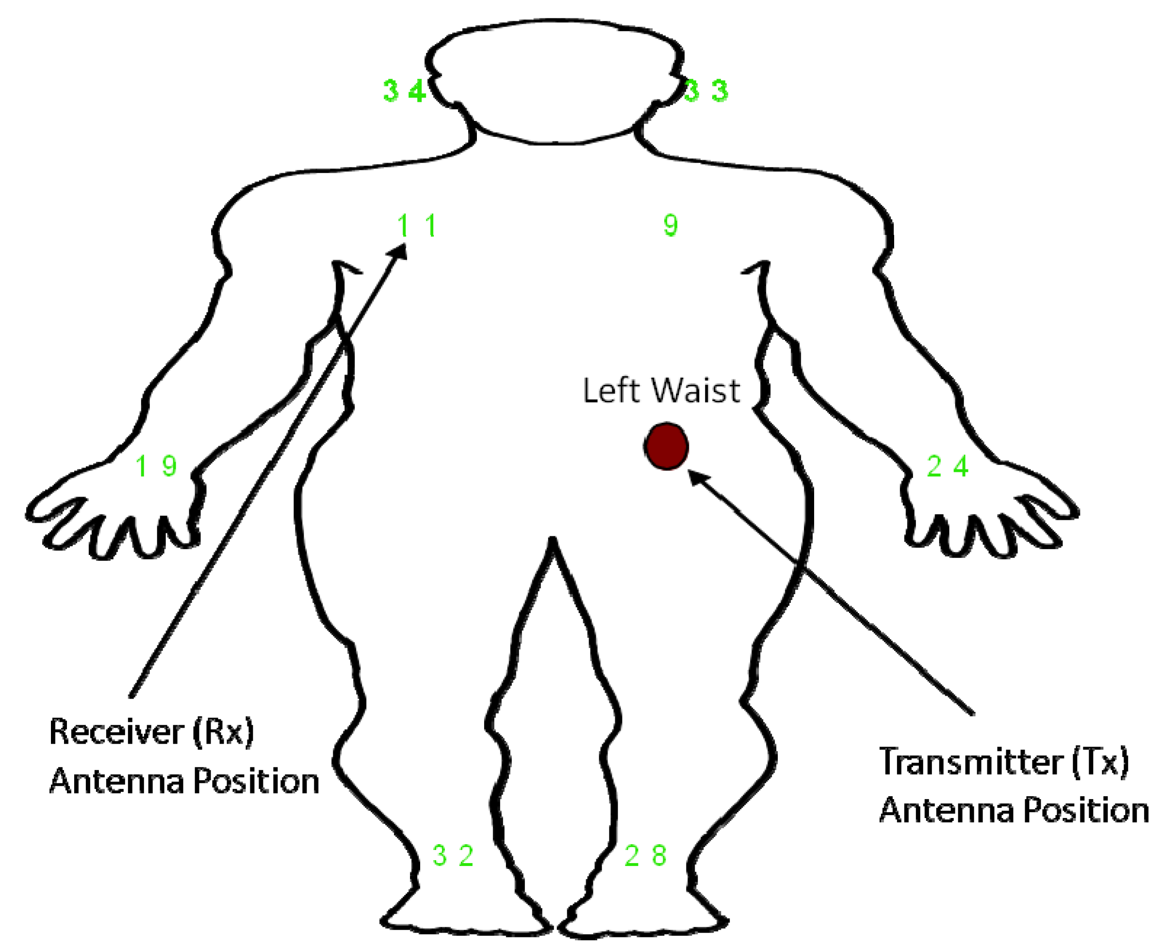
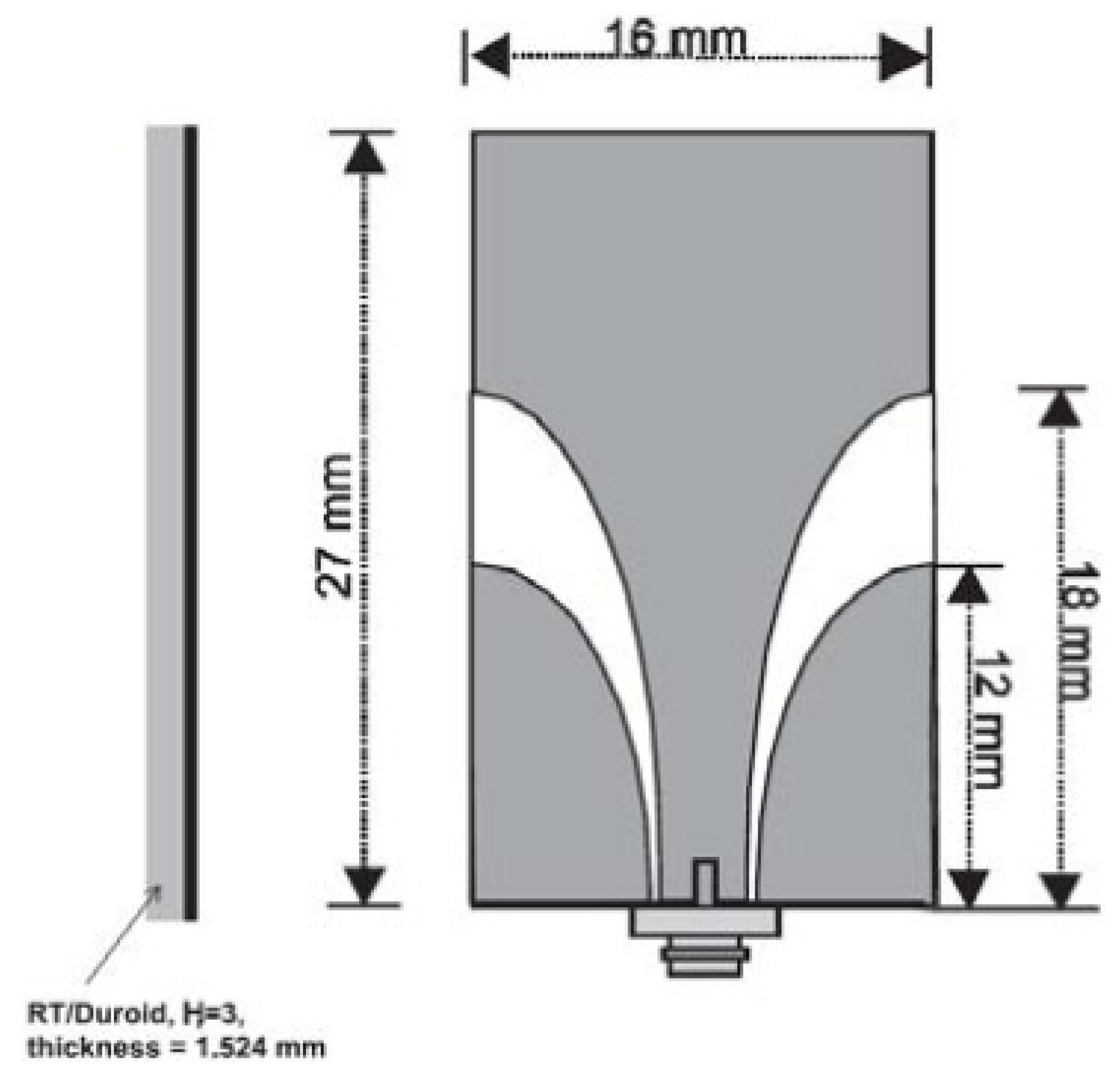
3.1. Measurement Settings

The UWB subject-specific on-body radio channel measurements were also performed in the frequency domain, using a vector network analyser (Hewlett Packard 8720ES-VNA) and two cables, connecting two stand-alone identical TSA antennas, to measure the transmission response (S21) in the frequency range of 3–10 GHz. The frequency range was set to 3–10 GHz, with 1601 points and with a sweep time of 800 ms. Like the narrowband study, 34 different receiver locations were considered. For this case, the transmitter and receiver antennas were placed exactly on the same locations as for the narrowband case. During the measurements, the subject was standing still, and for each receiver location and measurement scenario, 10 sweeps were considered, as was performed for the narrowband case. The UWB subject-specific on-body radio channel measurements were also performed in the Body-Centric Wireless Sensor Laboratory, Queen Mary University of London [31]. For both narrowband and UWB subject-specific on-body radio channel experiments, the environment of the sensor laboratory was kept constant.
Figure 8. Dimensions and geometry of the coplanar waveguide (CPW)-fed tapered slot antenna (TSA) used in this study [33].
Electronics 03 00026 g008

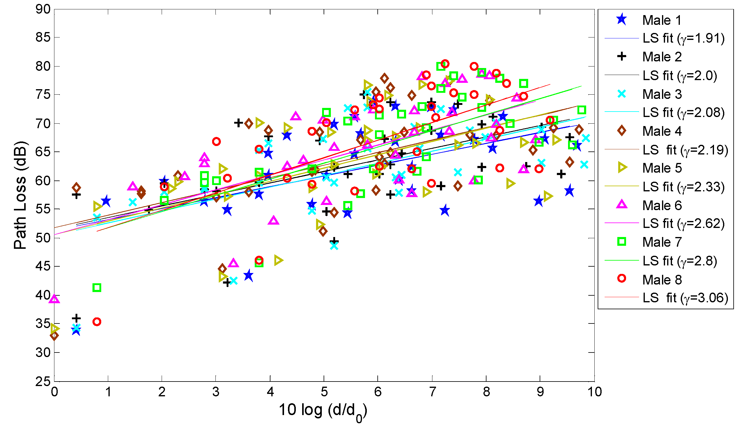
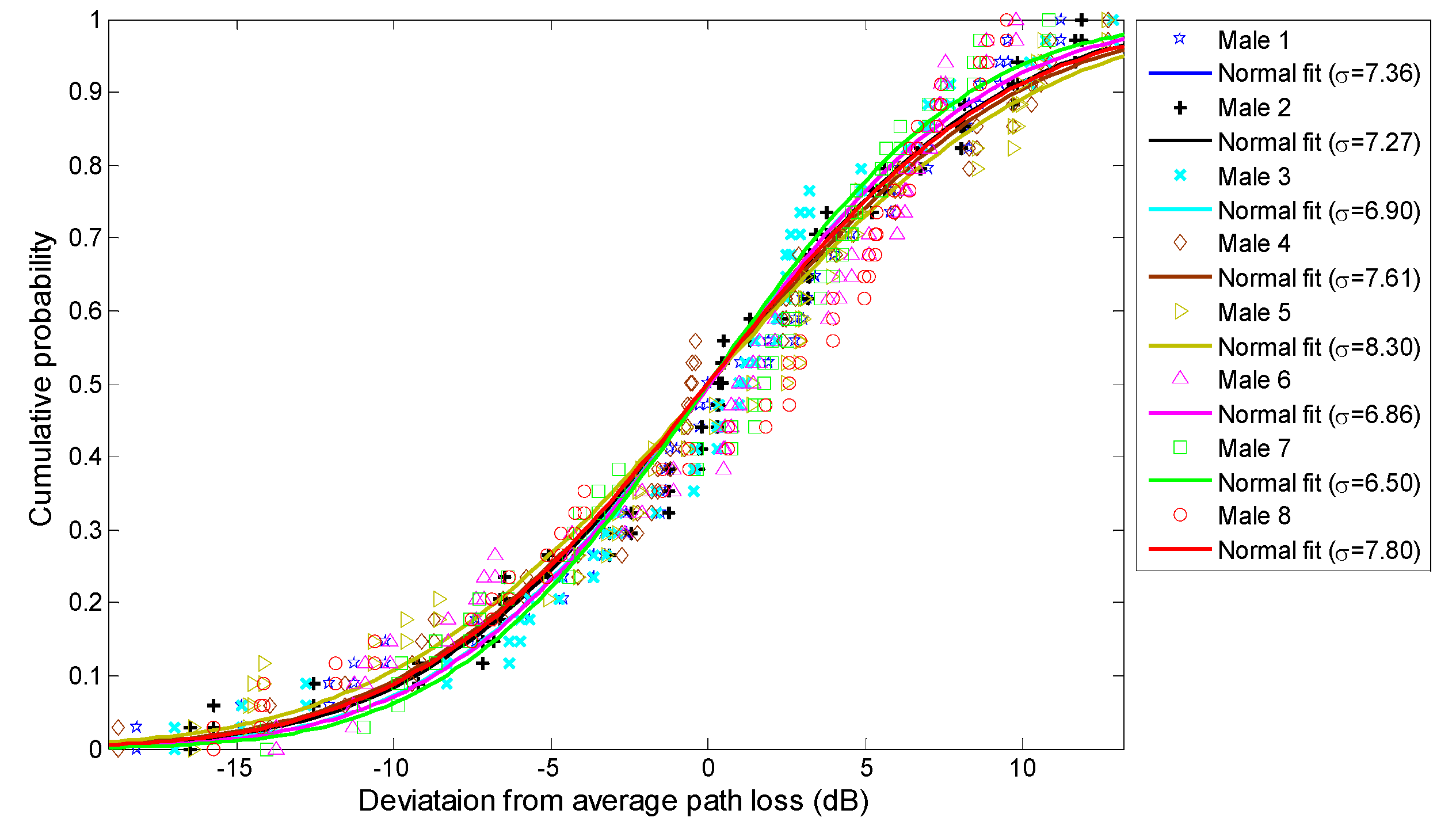
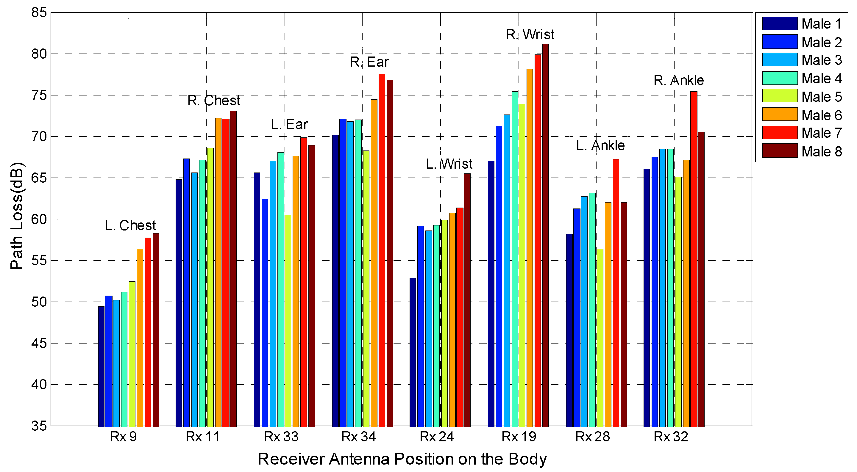
3.2. UWB On-Body Path Loss Characterisation

The path loss for each receiver location is directly calculated from the measurement, averaging over the frequency band of 3–10 GHz. A least-squares fit method is applied on the measured path loss data for 34 different receiver locations to extract the path loss exponent for eight test subjects, as shown in Figure 9. Table 4 lists the values of path loss exponent γ obtained for different test subjects. It can be noted that the path loss is affected by the body size. The conclusions are similar to the ones drawn in the previous section for a narrowband system. In particular, it is noted that subjects with a larger body size show higher values of the path loss exponent. For the UWB case, the value of the path loss exponent, γ, ranges from 1.91 (Male 1) to 3.06 (Male 8). It can be noted that subjects (such as Male 6, Male 7 and Male 8) having a bigger curvature radius at the waist and chest hence present a higher value of γ. For the UWB case, due to different body sizes, shapes and heights, a maximum variation in the path loss exponent of 1.15 is noticed (Male 1 and Male 8). For this case, Male 1 has the lowest chest and waist size circumferences compared with Male 8, resulting in the lowest path loss exponent.
Figure 9. Measured and modelled path loss for ultra-wideband on-body channel versus the logarithmic Tx-Rx separation distance of different human test subjects (Male 1–Male 8).
Electronics 03 00026 g009
Figure 10 shows the deviation of measurements from the average path loss fitted to a normal distribution for the eight different test subjects for the UWB case. The values of the standard deviation, σ, of the shadowing factor obtained for eight different test subjects are listed in Table 4. As with the narrowband results, the standard deviation, σ, of the normal distribution was found to be higher for Male 5 and Male 8. Results indicate that the standard deviation value, σ, varies for different test subjects, as was found in the narrowband system.
Figure 10. Deviation of the measurements from the average path loss for different test subjects (Male 1 to Male 8) fitted to a normal distribution at the UWB.
Electronics 03 00026 g010
Table 4. Ultra-wideband on-body path loss parameters for different test subjects. The parameter, γ, is the path loss exponent, PLdB(d0) is the path loss at the reference distance and σ is the standard deviation of the normally distributed shadowing factor.
Path Loss ParametersMale 1Male 2Male 3Male 4Male 5Male 6Male 7Male 8
γ1.912.02.082.192.332.622.83.06
PLdB(d0)51.251.650.451.850.750.549.048.7
σ7.367.276.907.618.306.866.607.80
Like the narrowband system, eight different on-body radio communication channels (as shown in Figure 6) have been chosen for the UWB case, in order to compare the path loss for eight different human body types. Figure 11 shows the variation in path loss for eight different ultra-wideband on-body radio links of different human test subjects. Due to different shapes and sizes of the human body, the path loss varies for each different receiver location on the body. For the considered eight different radio links, a maximum of 14.21 dB of variation in the path loss of an ultra-wideband on-body radio channel was observed. The maximum variation of path loss is noted for the transmitter for the right wrist link (Rx 19) of Male 1 and Male 8. In the UWB case, the same conclusion is drawn as in the previous section for a narrowband system. In particular, subjects with higher chest and waist circumferences (Male 6, Male 7 and Male 8) show a higher path loss value for the wrist links, compared with the subjects with smaller chest and waist sizes (Male 1, Male 2 and Male 3). For different subjects, the higher path loss variation is noticed for the receivers on the wrists and on the ankles, while the lowest path loss variation is noticed for the ear and chest links. Table 5 summarizes the maximum variation of the path loss for different on-body channels of different test subjects.
Figure 11. Variation of the path loss for eight different UWB on-body radio propagation channels of different human test subjects.
Electronics 03 00026 g011
Table 5. The maximum variation in the path loss of each on-body radio link obtained among different subjects (UWB).
ChannelMaximum path loss (dB) variation
Left chest 8.8
Right chest8.24
Left ear 9.4
Right ear 9.28
Left wrist 12.62
Right wrist 14.21
Left ankle 10.89
Right ankle 10.29
For the UWB system, the lowest path loss value is noticed for the left wrist and left chest links for all eight test subjects. The path loss for each different location is averaged over the eight test subjects. The averaged path loss for the left chest, right chest, left ear, right ear, left wrist, right wrist, left ankle and right ankle is 53.50, 68.80, 66.20, 72.84, 59.62, 74.87, 61.59 and 68.55 dB, respectively. Results show that for the UWB system case, the subject-averaged highest path loss is noticed for the right wrist, right ear and right chest channels, while the lowest is for left chest and left wrist channels. For the UWB case, nearly the same trends are noticed as was noticed for the narrowband case.

4. Narrowband vs. Ultra-Wideband Subject-Specific On-Body Radio Propagation Channels

Based on the studies in the previous two sections, a comparison between narrowband and ultra-wideband subject-specific on-body channel characterisation is made here.
  • For the narrowband case at 2.45 GHz, the path loss exponent is in the range of 3.20 to 4.05, while for the UWB (3–10 GHz) case, it is in the range of 1.91 to 3.06.
  • It is noted that, for the narrowband on-body radio propagation case, due to the different sizes, shapes and heights of the test subjects, the path loss exponent value varies up to a maximum of 0.85. For the UWB case, for different subjects, the path loss exponent value varies up to a maximum of 1.15. From this study, it is observed that, for different test subjects, the ultra-wideband system shows a higher variation of the path loss exponent value (0.3). The maximum path loss exponent variation for different test subjects in the UWB case is very close to the narrowband system. Table 6 summarises the dimensions and narrowband and UWB path loss exponents of the eight test subjects.
  • For the eight different on-body links considered, for different test subjects, a maximum of 13.02 dB of variation in path loss value of an on-body radio channel (left waist to right wrist) is noticed for the narrowband system, while for the UWB system, it is noticed to be 14.21 dB. For the UWB case, nearly the same trends are noticed as was observed for the narrowband case.
  • The values of path loss exponents γ are found to be higher for the narrowband case than the ones found for the UWB system. In the narrowband case, there is only one frequency band of operation (2.45 GHz), which has fewer effects (reflection, diffraction, scattering and so on) from the indoor environments and human body parts. On the other hand, in the UWB case, there are many frequency components (3–10 GHz) that have more effects from indoor environments and human body parts, resulting in a lower path loss exponent, as compared with the narrowband case. UWB technology is highly robust in multipathing; hence, the path loss value is lower at a higher distance, resulting in a lower path loss exponent.
  • At the reference distance, the path loss value is found to be higher for the UWB on-body radio channel (average, 8 dB) compared with the narrowband system. At lower communication distances between the Tx and Rx, the path loss value for UWB on-body radio channels is found to be higher compared with the narrowband case (such as the left wrist and left chest links).
Table 6. The dimensions (heights, shapes and sizes) and narrowband and UWB path loss exponents of the eight test subjects.
Dimensions and path loss exponents Male 1Male 2Male 3Male 4Male 5Male 6Male 7Male 8
Height (cm)182181186178169168188180
Chest circumference (cm)8791929394114124136
Waist circumference (cm)798182868996130140
Weight (kg)707374786891120128
Path loss exponents (γ) for the narrowband system at 2.45 GHz3.203.253.313.393.483.713.854.05
Path loss exponents (γ) for the UWB system at 3–10 GHz1.912.02.082.192.332.622.83.06

5. Conclusions

In this paper, the subject-specificity of the narrowband (at 2.45 GHz) and ultra-wideband (3–10 GHz) on-body radio channels in wireless body area networks (WBANs) was investigated by considering eight human test subjects of different shapes, heights and sizes. The experimental investigation was made in the indoor environment. The impact of different body shape, height and size on the on-body radio communication channel path loss was investigated and analysed at 2.45 GHz and 3–10 GHz. The results demonstrated that both the narrowband and ultra-wideband on-body radio propagation channels are subject-specific. Results demonstrated that, due to the different sizes, heights and shapes of the test subjects, the path loss exponent value varies up to a maximum of 0.85 for the narrowband on-body case, whereas a maximum variation of the path loss exponent value of 1.15 is noticed for the UWB case. The maximum path loss exponent variation for different test subjects in the UWB case is very close to the narrowband cases. The effect of the human body shape and size variations on the eight different on-body radio channels is studied, in which the results demonstrated that, for certain on-body links (e.g., left waist to right wrist), the changes in body shape can lead to a significant variation (up to 13.02 dB for narrowband and 14.21 dB for the UWB case) in the path loss. The results indicate that, for different test subjects, the path loss varies as maximum for the wrist and ankle channels and minimum for the ear and chest links in both cases. The UWB and narrowband systems show nearly the same trends of path loss for different on-body locations for different test subjects.

Acknowledgments

The authors of this paper would like to thank John Dupuy for his help with the antenna fabrication. The authors also would like to thank the human test subjects for their help during the measurements.

Conflicts of Interest

The authors declare no conflict of interest.

References

  1. Hall, P.S.; Hao, Y. Antennas and propagation for Body-Centric Wireless Communications. Antenn. Propag. 2006. [Google Scholar] [CrossRef]
  2. Fort, A.; Desset, C.; Doncker, P.D.; Biesen, L.V. Ultra wideband body area propagation: From statistics to implementation. IEEE Trans. Microw. Theory Tech. 2006, 54, 1820–1826. [Google Scholar] [CrossRef]
  3. Drude, S. Requirements and application scenarios for body area networks. In Proceedings of the 16th IST Mobile and Wireless Communications Summit; Budapest, Hungary: 1–5 July 2007.
  4. Bernhard, J.; Nagel, P.; Hupp, J.; Strauss, W.; von der Grun, T. BAN-body area network for wearable computing. In Proceedings of the 9th Wireless World Research Forum Meeting, Zurich, Switzerland, 1–2 July 2003.
  5. Jovanov, E.; O’Donnell Lords, A.; Raskovic, D.; Cox, P.; Adhami, R.; Andrasik, F. Stress monitoring using a distributed wireless intelligent sensor system. IEEE Eng. Med. Biol. Mag. 2003, 22, 49–55. [Google Scholar]
  6. Timmons, N.F.; Scanlon, W.G. Analysis of the performance of IEEE 802.15.4 for medical sensor body area networking. In Proceedings of the 1st Annual IEEE Communications Conference Sensor and Ad Hoc Communications and Networks (SECON), Santa Clara, CA, USA, 4–7 October 2004; pp. 16–24.
  7. Alomainy, A.; Hao, Y.; Owadally, A.; Parini, C.G.; Nechayev, Y.; Constantinou, C.C.; Hall, P.S. Statistical analysis and performance evaluation for on-body radio propagation with microstrip patch antenna. IEEE Trans. Antenn. Propag. 2007, 55, 245–248. [Google Scholar]
  8. Nechayev, Y.; Hall, P.; Constantinou, C.C.; Hao, Y.; Owadally, A.; Parini, C.G. Path loss measurements of on-body propagation channels. In Proceedings of the International Symposium on Antennas and Propagation, Sendai, Japan, 17–21 August 2004; pp. 745–748.
  9. Hall, P.S.; Nechayev, Y.; Hao, Y.; Alomainy, A.; Kamaruddin, M.R.; Constantinou, C.C.; Dubrovka, R.; Parini, C.G. Radio characterisation and antennas for on-body communications. In Proceedings of the Loughborough Antennas and Propagation Conference, Loughborough, UK, 4–6 April 2005; pp. 330–333.
  10. Hao, Y.; Alomainy, A.; Hall, P.S.; Nechayev, Y.I.; Parini, C.G.; Constantinou, C.C. Antennas and propagation for body-centric wireless communications. In Proceedings of the IEEE/ACES International Conference on Wireless Communications and Applied Computational Electromagnetics, Honolulu, HI, USA, 3–7 April 2005.
  11. Hu, Z.; Nechayev, Y.; Hall, P.S.; Constantinou, C.; Hao, Y. Measurements and statistical analysis of on-body channel fading at 2.45 GHz. IEEE Antenn. Wirel. Propag. Lett. 2007, 6, 612–615. [Google Scholar]
  12. Rahim, H.A.; Malek, F.; Hisham, N.; Malek, M.F.A. Statistical analysis of on-body radio propagation channel for body-centric wireless communications. In Proceedings of the PIERS, Stockholm, Sweden, 12–15 August 2013.
  13. Cotton, S.L.; Conway, G.A.; Scanlon, W.G. A time-domain approach to the analysis and modeling of on-body propagation characteristics using synchronized measurements at 2.45 GHz. IEEE Trans. Antenn. Propag. 2009, 57, 943–955. [Google Scholar] [CrossRef]
  14. Cotton, S.L.; Scanlon, W.G. An experimental investigation into the influence of user state and environment on fading characteristics in wireless body area networks at 2.45 GHz. IEEE Trans. Wirel. Commun. 2009, 8, 6–12. [Google Scholar] [CrossRef]
  15. Alomainy, A.A.; Hao, Y.; Parini, C.G.; Hall, P.S. Comparison between two different antennas for UWB on-body propagation measurements. IEEE Antennas Wirel. Propag. Lett. 2005, 4, 31–34. [Google Scholar] [CrossRef]
  16. Sani, A.; Hao, Y. Modeling of path loss for ultrawide band body-centric wireless communications. In Proceedings of the International Conference on Electromagnetics in Advance Applications (ICEAA), Torino, Italy, 14–18 September 2009; pp. 998–1001.
  17. Fort, A.; Desset, C.; Ryckaert, J.; Donker, P.D.; Biesen, L.V.; Wambackq, P. Characterization of ultra wideband body area propagation channel. In Proceedings of the International Conference on Ultra Wideband, Zurich, Switzerland, 5–8 September 2005.
  18. Wang, Q.; Wang, J. Performances of on-body chest-to-waist UWB communication link. IEEE Microw. Wirel. Compon. Lett. 2009, 19, 119–121. [Google Scholar] [CrossRef]
  19. Zasowski, T.; Althaus, F.; Stager, M.; Wittneben, A.; Troster, G. UWB for non-invasive wireless body area networks: Channel measurements and results. In Proceedings of the IEEE Conference on Ultra Wideband Systems and Technologies, Reston, VA, USA, 16–19 November 2003.
  20. Alomainy, A.; Hao, Y.; Hu, X.; Parini, C.G.; Hall, P.S. UWB on-body radio propagation and system modeling for wireless body-centric networks. IEE Proc. Commun. 2006, 153, 107–114. [Google Scholar] [CrossRef]
  21. Abbasi, Q.H.; Sani, A.; Alomainy, A.; Hao, Y. Radio channel characterization and system-level modeling for multiband OFDM ultra wideband body-centric wireless networks. IEEE Trans. Microw. Theory Tech. 2010, 58, 3485–3492. [Google Scholar]
  22. Sani, A.; Palikaras, G.; Alomainy, A.; Hao, Y. Time domain UWB radio channel characterisation for body-centric wireless communications in indoor environment. In Proceedings of the IET Seminar on Wideband and Ultrawide-band Systems and Technologies: Evaluating Current Research Development, London, UK, 6 November 2008.
  23. Sani, A.; Alomainy, A.; Hao, Y. Effect of the indoor environment on the UWB on-body radio propagation channel. In Proceedings of the 3rd European Conference on Antennas and Propagation (EuCAP), Berlin, Germany, 23–27 March 2009; pp. 455–458.
  24. Khan, M.M.; Abbasi, Q.H.; Alomainy, A.; Hao, Y. Performance of ultrawideband wireless tags for on-body radio channel characterization. Int. J. Antenn. Propag. 2012. [Google Scholar] [CrossRef]
  25. Abbasi, Q.H.; Alomainy, A.; Hao, Y. Experimental investigation of ultra wideband diversity techniques for antennas and radio propagation in body-centric wireless communications. Prog. Electromagn. Res. C 2013, 34, 165–181. [Google Scholar] [CrossRef]
  26. Khan, M.M.; Abbasi, Q.H.; Liaqat, S.; Alomainy, A. Comparison of two measurement techniques for UWB off-body radio channel characterisation. Prog. Electromagn. Res. M 2012, 27, 179–189. [Google Scholar] [CrossRef]
  27. Maskooki, A.; Soh, C.B.; Gunawan, E.; Low, K.S. Ultra-wideband real-time dynamic channel characterization and system-level modeling for radio links in body area networks. IEEE Trans. Microw. Theory Tech. 2013, 61, 2995–3004. [Google Scholar] [CrossRef]
  28. Khan, M.M.; Abbasi, Q.H.; Hossain, N.; Afroze, R.; Masud, A.A. On-body radio channel measurements for three different human body sizes. In Proceedings of the 15th International Conference on Computer and Information Technology (ICCIT), Chittagong, Bangladesh, 22–24 December 2012; pp. 230–234.
  29. Abbasi, Q.H.; Sani, A.; Alomainy, A.; Hao, Y. Numerical characterisation and modelling subject-specific ultra wideband body-centric radio channels and systems for healthcare applications. IEEE Trans. Inf. Technol. Biomed. 2012, 16, 221–227. [Google Scholar] [CrossRef]
  30. Zhao, Y.; Sani, A.; Hao, Y.; Lee, S.L.; Yang, G.Z. A simulation environment for subject-specific radio channel modeling in wireless body sensor networks. In Proceedings of the Sixth International Workshop on Wearable and Implantable Body Sensor Networks(BSN), Berkeley, CA, USA, 3–5 June 2009; pp. 23–28.
  31. Suma, M.N.; Bybi, P.C.; Mohanan, P. A wideband printed monopole antenna for 2.45 GHz WLAN applications. Microw. Opt. Technol. Lett. 2006, 48, 871–873. [Google Scholar] [CrossRef]
  32. Gassemzadeh, S.S.; Jana, R.; Rice, C.W.; Turin, W.; Tarohk, V. A statistical path loss model for in-home UWB channels. In Proceedings of the IEEE Conference Ultrawide Band Systems and Technologies, Baltimore, MD, USA, 21–23 May2002; pp. 59–64.
  33. Rahman, A.; Hao, Y. A novel tapered slot CPW-fed antenna for ultra-wideband applications and its on/off body performance. In Proceedings of the International Workshop on Antenna Technology, (IWAT), Cambridge, UK, 21–23 March 2007.

