Article

Elimination of Static Angular Error and Stability Enhancement for Active Power-Synchronized Converter Under a Weak Grid

by
Tong Zhao
,
Chao Wu
* and
Yong Wang
School of Electronic Information and Electrical Engineering, Shanghai Jiaotong University, Shanghai 200240, China
*
Author to whom correspondence should be addressed.
Electronics 2025, 14(9), 1781; https://doi.org/10.3390/electronics14091781
Submission received: 25 March 2025 / Revised: 21 April 2025 / Accepted: 24 April 2025 / Published: 27 April 2025

Abstract

:
A phase-locked loop (PLL), as a synchronization unit commonly employed in grid-connected converters (GCCs), jeopardizes system stability under a weak grid. Therefore, synchronization units without a PLL, such as active power synchronization (APS), have received much attention. However, GCCs adopting APS suffer from two typical issues: static angular error and the risk of destabilization. In this paper, the mechanism for static angular error is analyzed, which is attributed to the presence of active power current, resulting in a non-zero q-axis voltage at the point of common coupling. To eliminate the static error in angular tracking, conventionally, a proportional–integral (PI) controller is integrated into APS, which arouses system instability. Thus, a closed-loop single-input single-output (SISO) model of a GCC is derived from angular perturbation to analyze the mechanism of this destabilization. It is revealed that the gain overshoot in the closed-loop SISO model resulting from the PI controller would lead to system instability under a weak grid. Consequently, according to the above mechanistic analysis, a composite direct damping controller is proposed, which achieves the elimination of static angular error while enhancing system stability. Finally, the effectiveness of the mathematical analysis and derived models are verified by experimental results.

1. Introduction

With the gradually growing penetration of power electronics into the power grid, more and more grid-connected converters (GCCs) are being equipped. The control structure commonly adopted in GCCs is vector current control (VCC), achieving the decoupling control of active and reactive power, which is performed based on the angle of the point of common coupling (PCC) voltage obtained by the phase-locked loop (PLL). However, oscillations occur in GCCs employing a PLL under a weak grid [1,2]. According to the research conducted in [3,4,5], the negative impedance introduced by the dynamics of the PLL contributes to system instability. Thus, several methods have been developed to enhance the stability of GCCs. Among these methods, improvement in the synchronization unit (SU) is an effective method to strengthen the robustness of the GCC system. Based on the existing literature, improvements in the SU can be broadly classified into two categories. One is improvements that are implemented via the voltage-based synchronization method (VSM), which is usually realized by a PLL [3,4,5,6,7,8,9,10,11,12,13] and a voltage modulation matrix [14,15,16,17], to achieve enhancements in system stability. The other one is enhancing system stability by replacing the PLL in GCCs with the power-based synchronization method (PSM) [18,19,20,21,22].
Some modifications are performed in the PLL to enhance the stability of GCCs adopting a PLL under a weak grid [6,7,8,9,10,11,12,13]. In [6] and [7], GCCs are stabilized by reducing the bandwidth of the PLL at the expense of dynamic performance. Parameter design guidelines for PLLs are proposed in [8] and [9] to improve system stability. Nonetheless, these methods essentially involve a trade-off between the dynamic and static performance of the PLL. Furthermore, several parallel bandpass filters are integrated into the PLL to diminish the impact of voltage fluctuations in the PLL under a weak grid [10]. Moreover, [11,12] adopt a second-order generalized integrator (SOGI) to extract the signal at grid frequency to suppress the influence of PCC voltage fluctuation on controllers, which enhances the stability of the system by sacrificing dynamic performance. Nevertheless, it only enhances the stability of the system at a specific oscillation frequency. A strategy for reshaping the output impedance based on two PLLs is proposed in [13] to compensate for the impact of angular dynamics on the Park transformation so that the negative impedance is suppressed. All the above methods increase the complexity of the GCC system. On the other hand, a voltage modulation matrix is proposed in [14,15,16] to realize the synchronization process, which is proposed to avoid negative resistance existing in the PLL. However, it is indicated that the voltage modulation matrix is an open-loop PLL with infinite bandwidth, resulting in a lack of filtering capability to eliminate the frequency coupling phenomenon in [17], which deteriorates system stability.
Due to the limitations of the PLL and voltage modulation matrix discussed above, a PSM is developed to enhance the stability of GCCs under a weak grid [18,19,20,21,22]. Active power synchronization (APS) is usually adopted to track the angle of PCC voltage due to its correlation with angular frequency. However, the angular error introduced by APS cannot be eliminated by adopting only the current control loop [18]. This can be attributed to the fact that conventional APS is a first-order controller. As a result, it cannot track the ramp angular signal without static errors. Therefore, APS usually needs to be adopted together with a proportional–integral controller to accomplish the angular tracking process without static angular errors, which also contribute to system instability. The APS systems proposed in [19] and [20] restructure the system to attain the desired performance based on a precise plant model. However, the performance of these controllers depends heavily on the accuracy of the plant model, which is detrimental to their robustness and versatility. In addition, [21] demonstrates that a reactive power-based synchronization method (APS) can provide similar inertia to active power-based synchronization for GCCs. Therefore, APS is proposed in [22], where a q-axis voltage loop and q-axis damping controller are introduced to eliminate static angular errors and maintain the stability of GCCs. Yet, the additional q-axis voltage loop and the damping controller intensify the coupling of active and reactive power.
To overcome the drawbacks of the VSM and PSM, APS accompanied with a composite direct damping controller (DP-APS) is developed in this paper, which eliminates the static angular error while enhancing the stability of GCCs under a weak grid without compromising dynamic performance. Moreover, since the proposed composite direct damping controller guarantees that the q-axis voltage is 0 p.u. without influencing the current control, the decoupling control of active and reactive power is also realized.
From what has been discussed above, the contributions of this paper can be summarized as follows:
(1) The mechanism of static angular error generation in GCCs employing APS is analyzed, which reveals that it is closely related to the active power current generating a non-zero q-axis voltage at the PCC.
(2) Closed-loop single-input single-output (SISO) models of GCCs adopting APS, PI-APS and DP-APS are developed in this paper. It is demonstrated that the adoption of PI-APS eliminates the static angular error while leading to gain overshoot in the closed-loop SISO model, jeopardizing system stability under a weak grid.
(3) As a result, a composite direct damping controller is proposed in this paper to eliminate the static angular error while enhancing system stability, which is derived from equating the impact of angular dynamics on VCC to SU so that VCC is independent of the proposed damping controller, guaranteeing the decoupling control of active and reactive power.
(4) Compared with conventional APS, PI-APS and DP-APS eliminate the static error in the phase-locked process. However, PI-APS finitely strengthens the stability of the GCC under a weak grid, which is not enough to guarantee a stable power output for GCC under a weak grid. Thus, DP-APS is developed in this paper, which sufficiently enhances the stability of GCCs under a weak grid. This can be attributed to the stronger effect of the direct damping controller than the proportional controller.
To clarify the mechanism of static angular error and destabilization in GCC employing APS and the proposed composite direct damping controller, this paper is organized as follows: Firstly, the mechanism by which the GCC adopts APS for the static angular error is investigated in Section 2, which indicates that the active power current matters. After that, the closed-loop SISO models of GCCs employing PLL, SOGI-PLL, APS, PI-APS and DP-APS are developed in Section 3 for the intuitive analysis. Based on the derived model, a composite direct damping controller is proposed to eliminate the static angular error and enhance system stability. The closed-loop SISO model is verified in Section 4, where the dynamic performance of DP-APS and its enhancement effect on system stability are also evaluated. In Section 5, these synchronization methods are implemented on a 2 kVA GCC platform to verify the effectiveness of the analysis and the composite direct damping controller developed in this paper. Finally, the conclusions are drawn in Section 6.

2. Modeling and Analysis of Angular Errors in Vector Current Control Employing Active Power Synchronization

APS is an effective synchronization method for weak grids that improves the stability of the GCC system. Nevertheless, an angular error is generated when APS is adopted in vector current control, which results from the non-zero error orientation of the voltage caused by APS. As a result, currents on the d-axis and q-axis do not exactly correspond to the active and reactive power, so the advantages of VCC of realizing the decoupling control of active and reactive power cannot be exploited. In this section, the mechanism of the angular error generation when GCCs adopt APS is analyzed, which can be attributed to the fact that the q-axis voltage of the PCC is not equal to 0 p.u.

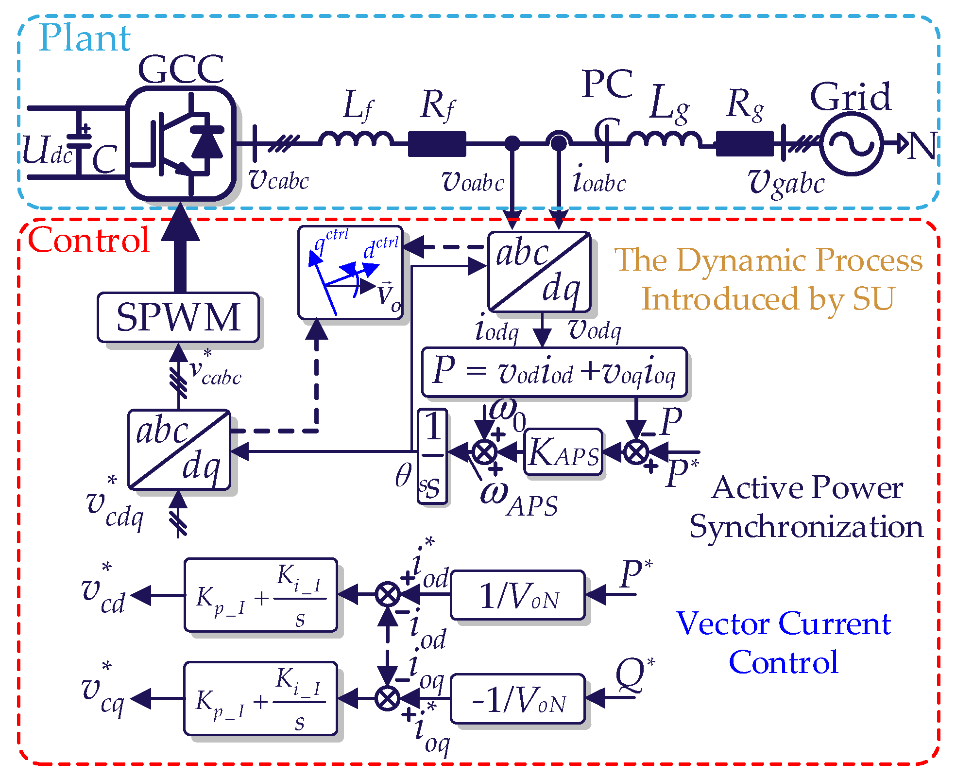
2.1. Description of the GCC System

The structure of the GCC system is shown in Figure 1, where vgabc and voabc represent the grid voltage and the PCC voltage, v*cabc and vcabc represent the reference and actual values of the converter voltage, ioabc represents the output current, θs is the output angle of SU, P* and P are the reference and actual values of active power, Q* and Q are the reference and actual values of reactive power, Gc(s) is the current controller, Lf and Rf are the inductance and resistance of the filter inductor, and Lg and Rg are the inductance and resistance of grid impedance. ω0 represents the synchronous angular frequency (ω0 = 100π rad/s). In addition, ωAPS represents the output angular frequency of APS. The parameters of the vector current controller are indicated as Kp_I and Ki_I. The presence of dynamic processes in the SU induces perturbations in the Park and inverse Park transformations, which are shaded for clarity.
As shown in Figure 1, the transfer function of APS is described as follows (1):
θ s = 1 s [ ω 0 + K A P S ( P * P ) ]

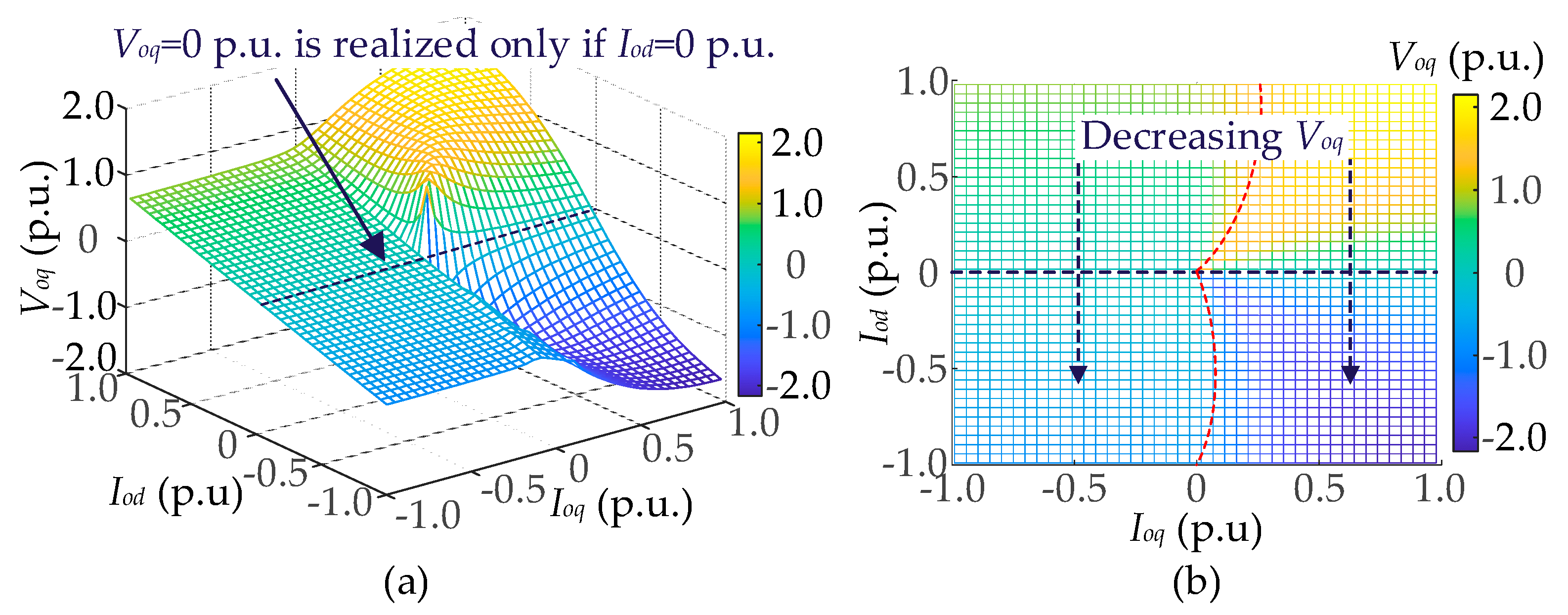
2.2. Analysis and Calculation of Operating Points for Grid-Connected Converter Employing Phase-Locked Loop

According to the circuit structure shown in Figure 2, the circuit between the voltage of the PCC Vo and the grid voltage Vg can be equated as follows (2):
V o = V g + I o Z g = V g + I o ( R g + j ω 0 L g )
where
V o = V od + jV oq , V g = V gd + jV gq , I o = I od + j I o q
Thus, depending on (2) and (3), the system of equations can be built as follows (4):
{ V o d = V g d + R g I o d ω 0 L g I o q V o q = V g q + R g I o q + ω 0 L g I o d V g = V g d 2 + V g q 2
Based on VCC, current control without the static error is realized, which is demonstrated as follows (5):
I o d = I o d * , I o q = I o q *
Since APS is adopted, P* = P is always satisfied. Then, this can be derived as follows (6):
{ P * = 1.5 V o N I o d * P = 1.5 ( V o d I o d + V o q I o q ) = P *
Combining (2)~(6), Vod and Voq can be calculated as follows (7):
V o d = { n 1 n 2 I o d ( I o d 2 + I o q 2 ) , I o d > 0 V o N , I o d = 0 n 1 + n 2 I o d ( I o d 2 + I o q 2 ) , I o d < 0 , V o q = { n 3 + n 4 I o d 2 + I o q 2 , I o d > 0 0 , I o d = 0 n 3 n 4 I o d 2 + I o q 2 , I o d < 0
where
n 1 = V o N I o d 3 I o d I o q X g ( I o d 2 + I o q 2 ) , n 2 = I o q | V o N I o d I o q | n 3 = V o N I o d I o q + I o d X g ( I o d 2 + I o q 2 ) , n 4 = | V o N I o d I o q |
When the angle of PCC voltage is accurately followed without static error, Voq = 0 p.u. is satisfied. Thus, based on (7) and (8), the constraint equation to guarantee that the angle tracking gets rid of the static angular error can be represented as (9). It can be detected that Iod = 0 p.u. is the only real solution fulfilling (9), regardless of variations in Ioq.
{ n 3 + n 4 I o d 2 + I o q 2 = 0 , I o d > 0 n 3 n 4 I o d 2 + I o q 2 = 0 , I o d < 0 { n 3 + n 4 = 0 , I o d > 0 n 3 n 4 = 0 , I o d < 0 { V o N I o d I o q + I o d X g ( I o d 2 + I o q 2 ) + | V o N I o d I o q | = 0 V o N I o d I o q + I o d X g ( I o d 2 + I o q 2 ) | V o N I o d I o q | = 0 I o d X g ( I o d 2 + I o q 2 ) = 0   or   2 V o N I o d I o q
To verify the correctness of (9), based on the above calculation method, the steady-state operating point with SCR = 1.8 for two typical operating conditions (case 1: Iod = 1.0 p.u. and Ioq = 0 p.u.; case 2: Iod = 0 p.u. and Ioq = −1.0 p.u) can be obtained. For a more intuitive demonstration, the above two operating points are shown in Figure 3. The angle between the d-axis and Vo is defined as θpcc, which is shown as (10). In addition, θ0 represents the angle of the d-axis. As shown in Figure 3a, θpcc≠0 rad is satisfied in case 1, which indicates that the d-axis in the control frame does not catch up with Vo, leading to the angular error. In addition, Voq = 0 cannot be realized in case 1, so Iod/Ioq and P/Q are not decoupled in this situation, which is detrimental to the precision of VCC. However, in case 2, the d-axis and Vo are coincident, contributing to a successful synchronization.
As discussed above, it is indicated that the synchronization results of the GCC adopting APS depend on operating points, which is unacceptable for the effective control of the GCC system.
θ p c c = arctan ( V o q / V o d )
For a more in-depth analysis of the influence of operating conditions on the effect of APS synchronization, the trend of variation in θpcc is investigated when Iod and Ioq change from −1.0 p.u. to 1.0 p.u. The results are illustrated in Figure 4a. To demonstrate the relationship between Iodq and θpcc more clearly, the 3D diagram in Figure 4b exhibits a detailed diagram of the top view, indicating that θpcc varies with Iod and Ioq. Thus, it can be noticed that θpcc = 0 rad is satisfied only when Iod = 0 p.u., regardless of variations in Ioq, which indicates that the angular error introduced by APS is absent only when P* = 0 p.u. This limited angular error synchronization realized by APS is detrimental to the decoupling control of P and Q in VCC.
Learning from the mechanism of precise synchronization achieved by PLL, the relationship between θpcc and Voq in the GCC employing APS is investigated. Thus, the trend of the variation in Voq while Iod and Ioq change from −1.0 p.u. to 1.0 p.u. is drawn in Figure 5a, the detailed top-view diagram of which is described in Figure 5b. As depicted in Figure 5a, the operating points for Voq = 0 p.u. coincide with the ones for θpcc = 0 rad, which is Iod = 0 p.u., which demonstrates that there is some correlation between θpcc = 0 rad and Iod = 0 p.u.
Based on the above discussion, it can be noticed that Iod = 0 p.u. guarantees that Voq = 0 p.u. is satisfied in the GCC adopting APS. Thus, the static angular error is eliminated. As a conclusion, the presence of Iod results in Voq ≠ 0 p.u., contributing to static angular errors in the angular tracking process.

3. Design Process of the Composite Direct Damping Controller

In this section, firstly, to analyze the mechanism for the generation of the static angular error, the closed-loop SISO model is developed. APS with a proportional–integral controller (PI-APS), as shown in Figure 6, is a conventional method to eliminate the static angular error, which generates an overshoot of gain in angular tracking, resulting in system instability. Therefore, a composite direct damping controller, which is derived from the small-signal analysis of the effect of the dynamics of the SU on the system, is proposed in this paper to suppress the gain overshoot to restabilize the system while eliminating the static angular error. The detailed parameters of the 2 kVA GCC system are listed in Table 1.

3.1. Derivation of the Closed-Loop SISO Model and Analysis of Angular Error for Grid-Connected Converter Employing Active Power Synchronization

Based on the transfer function of APS shown as (1), the small-signal model of Δθs, which is derived from Δiodq and Δvodq, can be expressed as follows (11):
Δ θ s = 1 s [ 3 K A P S 2 s ( I o d Δ v o d + I o q Δ v o q + V o d Δ i o d + V o q Δ i o q ) ]
After considering the impact of the actual angular perturbation of PCC voltage Δθpcc on the voltage through the Park transformation and assuming the amplitude of PCC voltage is constant, Δvodq can be expressed as follows (12):
{ Δ v o d = V o q Δ θ p c c Δ v o q = V o d Δ θ p c c
Limited by the length of this paper, the derivation process of the impedance model for the GCC employing APS, which is defined as Yc1(s), has been omitted. In addition, similar omissions are performed for GCCs adopting other SUs as well. Based on Yc1(s), Δiodq can be obtained by Δvodq, which is described as follows (13):
[ Δ i o d Δ i o q ] = [ Y c d d 1 Y c d q 1 Y c q d 1 Y c q q 1 ] [ Δ v o d Δ v o q ]
Combining (11), (12) and (13), the closed-loop SISO model between Δθs and Δθpcc when the GCC adopts APS can be obtained as
Δ θ s = G A P S ( s ) Δ θ p c c   = { 3 K A P S [ V o q ( I o d Y c d d 1 V o d Y c q d 1 V o q ) 3 K A P S V o d ( I o q Y c d q 1 V o d Y c q q 1 V o q ) ] } 2 s Δ θ p c c
Based on the analysis carried out above, the mechanistic analysis of how the effect of Δθpcc on Δθs occurs can be summarized as shown in Figure 7. It is indicated that Δθpcc contributes to Δvodq. Then, based on Yc1(s), Δiodq is generated by Δvodq, which is described as (13). Finally, Δvodq and Δiodq contribute to Δθs through the perturbation of active power.

3.2. Derivation of the Closed-Loop SISO Model and Analysis of Angular Error of Grid-Connected Converter Employing Conventional Phase-Locked Loop and Phase-Locked Loop with Second-Order Generalized Integer

Similarly, the closed-loop SISO model between Δθs and Δθpcc when PI-APS is employed as the SU can be described.
The structure of the conventional phase-locked loop is shown in Figure 8, which characterizes the effect generated by the fluctuations in PCC voltage Δvoq on the output angle of the PLL Δθs.
According to the small-signal model of the conventional PLL, the closed-loop transfer function of the conventional PLL TPLL1(s) is described as follows (15):
T P L L 1 ( s ) = s K p P L L 1 + K i P L L 1 s 2 + s V o d K p P L L 1 + V o d K i P L L 1
Due to the relationship between Δvoq and Δθpcc described in (12), the closed-loop SISO model of conventional is derived as follows (16):
Δ θ s = T P L L 1 ( s ) V o d Δ θ p c c   = ( s K p P L L 1 + K i P L L 1 ) V o d s 2 + s V o d K p P L L 1 + V o d K i P L L 1 Δ θ p c c
Typically, an SOGI is introduced to the conventional PLL to enhance the GCC stability under a weak grid. The transfer function of the SOGI in the αβ frame is derived as follows (17):
G S O G I ( s ) = 2 K S O G I ω S O G I s s 2 + 2 K S O G I ω S O G I s + ω S O G I 2
Since the analysis carried out in this paper is in the dq frame, GSOGI(s) is converted to the dq frame, which is derived as follows (18):
G S O G I ( s j ω 0 ) = 2 K S O G I ω S O G I ( s j ω 0 ) ( s j ω 0 ) 2 + 2 K S O G I ω S O G I ( s j ω 0 ) + ω S O G I 2
Thus, the SOGI in the dq frame is converted to a matrix, which is expressed as follows (19):
G S O G I _ d q ( s ) = [ K Re K Im K Im K Re ]
where the coefficients defined as KRe and KIm are as follows (20):
K Re = 2 K S O G I ω S O G I s ( s 2 ω 0 2 + ω S O G I 2 + 2 K S O G I ω S O G I s ) + 2 K S O G I ω S O G I ω 0 ( 2 s ω 0 + 2 K S O G I ω S O G I ω 0 ) ( s 2 ω 0 2 + ω S O G I 2 + 2 K S O G I ω S O G I s ) 2 + ( 2 s ω 0 + 2 K S O G I ω S O G I ω 0 ) 2 K Im = 2 K S O G I ω S O G I s ( 2 s ω 0 + 2 K S O G I ω S O G I ω 0 ) + 2 K S O G I ω S O G I ω 0 ( s 2 ω 0 2 + ω S O G I 2 + 2 K S O G I ω S O G I s ) ( s 2 ω 0 2 + ω S O G I 2 + 2 K S O G I ω S O G I s ) 2 + ( 2 s ω 0 + 2 K S O G I ω S O G I ω 0 ) 2
Moreover, the transfer function between Δθs and Δvod, Δvoq can be formed as follows (21):
Δ θ s = G S O G I _ d q ( s ) T P L L ( s ) Δ v o q = T P L L ( s ) ( K Im Δ v o d + K Re Δ v o q )
where
T P L L 2 ( s ) = s K p P L L 2 + K i P L L 2 s 2 + s V o d K p P L L 2 + V o d K i P L L 2
Based on (21), the structure of the small-signal model of SOGI-PLL is shown in Figure 9, which describes the relationship between Δvodq and Δθs.
Combining (12) and (21), the closed-loop SISO model of SOGI-PLL is derived as follows (23):
Δ θ s = G S O G I P L L ( s ) Δ θ p c c   = ( s K p _ P L L 2 + K i _ P L L 2 ) ( K Re V o d K Im V o q ) s 2 + s V o d K p _ P L L 2 + V o d K i _ P L L 2 Δ θ p c c

3.3. Analysis of GCC Employing APS and PI-APS for Stability Risk and Static Angular Error

Similarly, the closed-loop SISO model between Δθs and Δθpcc, when PI-APS is employed as the SU, can be obtained as (24). In addition, the impedance model of the GCC employing PI-APS is defined as Yc2(s).
Δ θ s = G P I A P S ( s ) Δ θ p c c   = { 3 s K A P S [ V o q ( I o d Y c d d 2 V o d Y c q d 2 V o q ) V o d ( I o q Y c d q 2 V o d Y c q q 2 V o q ) ] + 2 V o d ( s K p A u x 1 + K i A u x 1 ) } 2 ( s 2 + s K p A u x 1 V o d + K i A u x 1 V o d ) Δ θ p c c
Bode diagrams of GAPS(s) and GPI-APS(s) with P* varying from 0.4 p.u. to 1.0 p.u. are plotted in Figure 10. Since the tracking of Δθpcc is predominantly in low frequency, the frequency range of the bode diagrams is from 0.01 Hz to 100 Hz. As shown in Figure 10a, there are static errors enlarged with increasing P* in the tracking of Δθpcc in the GCC employing APS, which is consistent with the results shown in Figure 10a. However, when PI-APS is adopted in the GCC, static errors in the tracking of Δθpcc are eliminated independently from changes in P*, the results of which are described in Figure 10b. However, PI-APS induces an overshoot in the closed-loop SISO model, which prevents the fluctuations in Δθpcc from being attenuated, leading to the risk of system instability. The detailed stability analysis will be performed and validated in Section 4.

3.4. The Design Process of the Proposed Composite Direct Damping Controller

To design the proposed direct damping controller, the relationship between Δ v o q c t r l and Δθs is first analyzed from the mechanism perspective. Then, based on this mechanistic analysis, the composite direct damping controller is proposed.

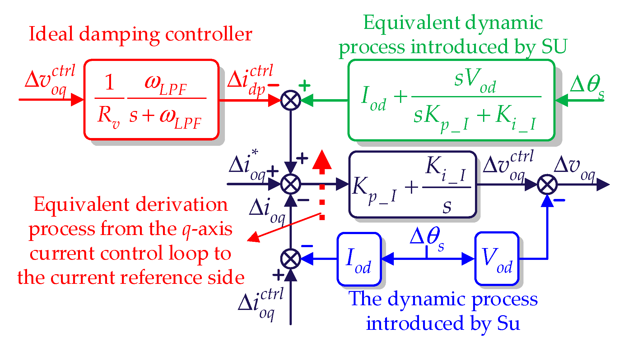
3.4.1. Mechanism Analysis and Design of the Proposed Composite Direct Damping Controller

Since the research in this paper is carried out mainly in the low- and medium-frequency bands, the delay caused by the digital control can be ignored. Thus, based on Figure 1, a small-signal model of VCC can be obtained, as shown in Figure 11. In addition, impacts generated by Δθs on the VCC are marked in blue, which deteriorates system stability.
As the elimination method for APS angular error in this paper is based on voq, the design of the damping controller proposed in this paper focuses on the control related to the q-axis. Then, Vcd,Vcq, Δ v c q c t r l and Δvcq can be expressed as follows (25):
{ V c d = V o d + R f I o d ω 0 L f I o q V c q = V o q + R f I o q + ω 0 L f I o d Δ v c q c t r l = Δ v o q c t r l + ( s L f + R f ) Δ i o q c t r l + ω 0 L f Δ i o d c t r l Δ v c q = Δ v o q + ( s L f + R f ) Δ i o q + ω 0 L f Δ i o d
When the GCC is stabilized at an operating point with precise angular tracking, Voq = 0 p.u. is achieved. Moreover, Rf and ω0Lf are relatively small enough so that their effects on Vcd and Vcq can be ignored. Thus, Vcd, Vcq, Δ v c q c t r l and Δvcq can be approximated as follows (26):
{ V c d V o d , V c q V o q = 0 Δ v c q c t r l Δ v o q c t r l , Δ v c q Δ v o q
The key idea of the damping controller discussed in this paper is designed to counteract the effect of Δθs by adding a damping current Δ i d p c t r l . As a result, a suitable variable and a damping controller need to be designed to generate Δ i d p c t r l to achieve the following two control objectives:
(1)
The selected variables, which are adopted by the proposed damping controller, should reflect fluctuations in the output angle of the SU so that the damping effect can be guaranteed.
(2)
The proposed damping controller functions only in the transient state and its inclusion should not affect the steady-state current reference value.
Based on the above two control objectives that need to be achieved, Δ v o q c t r l is chosen as the input of the proposed damping controller to generate Δ i d p c t r l . When the angular tracking is completed, the steady-state value of Δ v o q c t r l defined as Voq is 0. Thus, Δ v o q c t r l can indicate whether the angular tracking is successful while avoiding influencing the steady-state current reference value. For this purpose, a virtual resistor Rv is designed for Δ v o q c t r l to generate Δ i d p c t r l , where Δ i d q c t r l = 0 p.u. when v o q c t r l = 0 p.u. is satisfied. Since this paper is primarily concerned with oscillations at low and medium frequencies, a low-pass filter (ωLPF = 314 rad/s) is added in series with 1/Rv. As a result, an ideal damping controller is developed, which is described in Figure 12.
The purpose of the ideal damping controller is designed to suppress the perturbation of Δθs, which realizes the damping effect through the VCC. However, the ideal damping controller suffers from the risk of disrupting the decoupling control of active and reactive power achieved by the VCC. Therefore, the damping controller is preferably implemented in the SU directly. To realize the conversion of the damping controller from the VCC to the SU, the relationship between these two implementation paths must be derived and equivalent.
Based on (26) and Figure 9, the ideal realized damping effect can be expressed as (27), where it is assumed that the ideal damping controller counteracts the dynamics on the current side and voltage side, respectively.
{ s V o d s K p _ I + K i _ I Δ θ s = ω L P F R v ( s + ω L P F ) Δ v o q c t r l I o d Δ θ s = ω L P F R v ( s + ω L P F ) Δ v o q c t r l
Thus, combined with (26), the relationship between Δ v o q c t r l and Δωdp, which is the angular frequency perturbation corresponding to Δθdpωdp = sΔθdp), can be derived as follows (28):
Δ ω d p = G d p ( s ) Δ v o q c t r l   = ω L P F [ s ( V o d + I o d K p _ I ) + I o d K i _ I ] R v V o d I o d ( s + ω L P F ) Δ v o q c t r l
where Δωdp and Δθdp are the damping angular frequency and damping angle generated by the proposed direct damping controller to suppress the perturbation of Δθs.
As demonstrated in (28), it can be seen that the damping effect of DP-APS is related to the active power current Iod, which indicates the correlation between active power and angular frequency ω. Moreover, this also shows that the damping effect is dependent on the value of Iod. To get rid of this dependence on the working point, Vod = VoN and Iod = IoN are adopted. Thus, (28) can be modified as follows (29):
Δ ω d p = G d p ( s ) Δ v o q c t r l = K d ω L P F [ s K 1 + K 2 ] s + ω L P F Δ v o q c t r l
where
K 1 = V o N + I o N K p _ I , K 2 = I o N K i _ I , K d = 1 / R v V o N I o N
For the adjustment of the parameters involved in (29), K1 and K2 are only related to VoN, IoN and the parameters of the current loop so that they can be considered constant. Thus, the proposed direct damping controller only needs to adjust two parameters—Rv and ωLPF—to realize the damping control, where the damping strength is adjusted by Rv and the frequency range of the damping effect is determined by ωLPF.
Since Gdp(s) is essentially a lead–lag unit, the angular error is inevitably introduced. Thus, an integral controller is integrated into Gdp(s) so that a new composite controller called Gdpi(s) is obtained, which provides direct damping while ensuring accurate tracking of the angular dynamic without static errors.
Δ ω d p i = G d p i ( s ) Δ v o q c t r l = [ G d p ( s ) + K i A u x 2 s ] Δ v o q c t r l   = K d ( s 2 D 1 + s D 2 + D 3 ) s 2 + s ω L P F Δ v o q c t r l
where
D 1 = K 1 ω L P F , D 2 = K 2 ω L P F + K i A u x 2 , D 3 = K i A u x 2 ω L P F
Therefore, the practical implementation pathway of the proposed damping controller is converted from the current control loop to the synchronization unit, which is shown in Figure 13. As the control effect of the damping controller proposed in this paper functions directly on the synchronization unit, the proposed damping controller is called the direct damping controller.

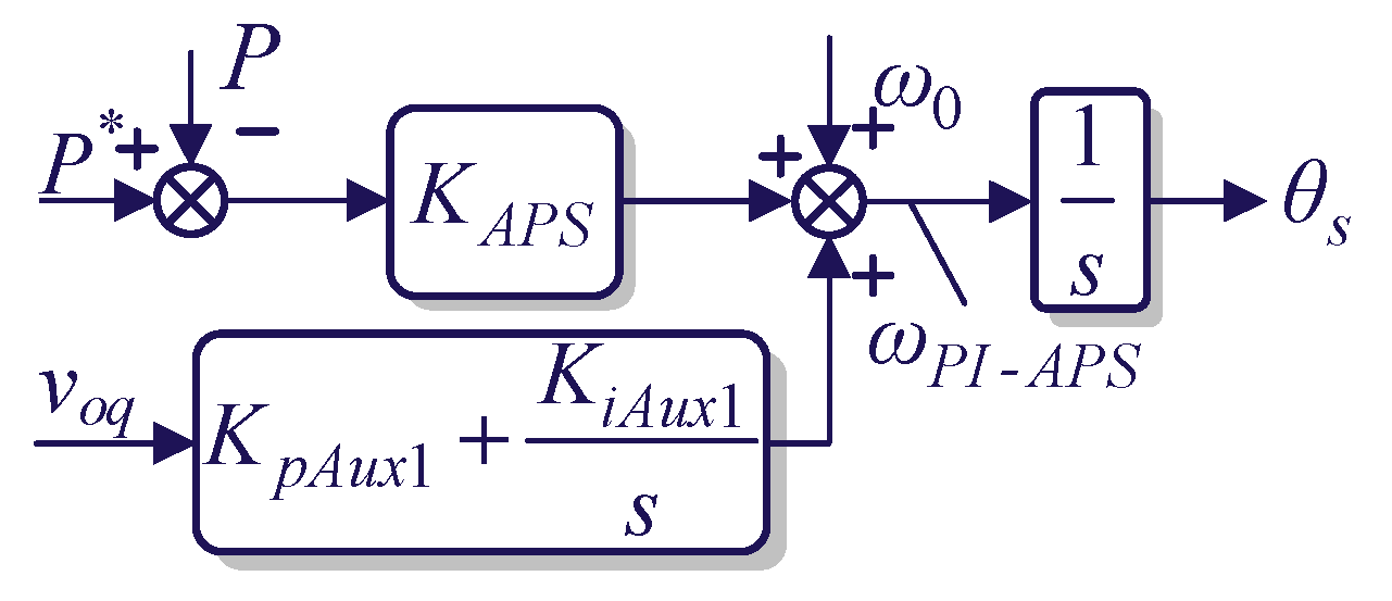
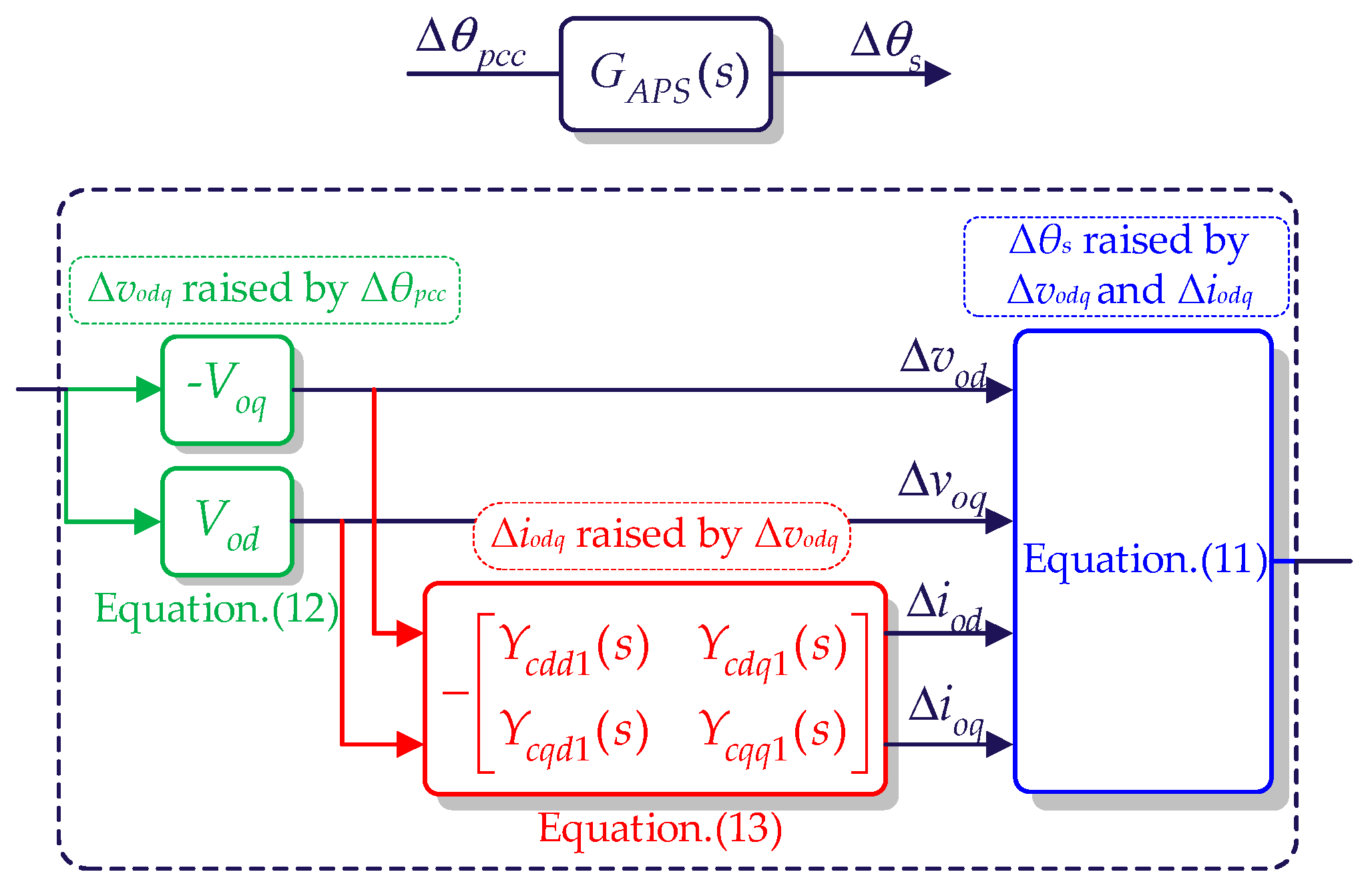
3.4.2. Impact of Angle Perturbations of PCC Voltage on the Output Angle in Active Power-Based Synchronization Method with the Direct Damping and Proportional–Integral Controller

Based on Figure 11, the relationship between Δθs, Δiodq, Δvodq, and Δ v o q c t r l in DP-APS can be expressed as follows (33):
Δ θ s = 1 s { 3 K A P S 2 s ( I o d Δ v o d + I o q Δ v o q + V o d Δ i o d + V o q Δ i o q )   + G d p i ( s ) Δ v o q c t r l }
Thus, the closed-loop SISO model of DP-APS is derived as (34). Besides, the impedance model of GCC employing DP-APS is called Yc3(s).
Δ θ s = G D p A P S ( s ) Δ θ p c c   = { 3 s K A P S [ V o q ( I o d Y c d d 3 V o d Y c q d 3 V o q ) V o d ( I o q Y c d q 3 V o d Y c q q 3 V o q ) ] + 2 V o d [ s G d p + K i A u x 2 ] } 2 [ s 2 + s G d p V o d + K i A u x 2 V o d ] Δ θ p c c

4. Dynamic Performance Analysis and Stability Evaluation of Grid-Connected Converter Employing the Proposed Composite Direct Damping Controller

In this section, based on the closed-loop SISO model derived in the previous section, the dynamic performance of GCCs adopting PLL, SOGI-PLL, PI-APS and DP-APS is analyzed, indicating that DP-APS does not compromise the dynamic performance. Moreover, a stability analysis of GCCs adopting different SUs containing PLL, SOGI-PLL, PI-APS and DP-APS is also undertaken so that the effectiveness of DP-APS for enhancing system stability can be validated.
The tuning process of the parameters in DP-APS is as follows: Firstly, since KAPS characterizes the relationship between the active power P and the output angular frequency of the GCC ωs, it can be calculated as follows (35):
K A P S = Δ ω s Δ P = 0.05 ω 0 P N = 0.008
The synchronization method defined as PI-APS contains PLL and active power synchronization (APS), where the APS is responsible for tracking the change in angular frequency and the change in phase angle is tracked by the PLL. Thus, the bandwidth of this PLL ωPLL is set as 25 Hz. To enhance the GCC’s stability, the damping ratio of the PLL ζ is changed to 1.12. Thus, the parameters of the PI controller in the PLL defined as KpAux1 and KiAux1 can be calculated as (36). As a result, the parameters of PI-APS are obtained.
K i A u x 1 = b + b 2 4 a c 2 a = 1.64 , K p A u x 1 = 2 ζ K i A u x 1 V g N = 43.09
where
ω P L L 1 = 2 π f P L L 1 , a = V g N 2 ,   b = 4 ζ 2 V g N ω P L L 1 2 + 2 V g N ω P L L 1 2 ,   c = ω P L L 1 4
As for DP-APS, in order for the dynamic performance of the GCC not to be compromised, the bandwidth of DP-APS is designated as 25 Hz. To simplify the design process of the parameters, KiAux2 in DP-APS is set to be the same as KiAux1. Since the direct damping controller is mainly aimed at signal suppression at low and medium frequencies, ωLPF = 314 rad/s is adopted. Based on the closed-loop SISO model of DP-APS derived in this paper, it can be found that the gain overshoot can be suppressed without compromising dynamic performance at Rv = 4.05Ω. As a result, the design of the parameters of DP-APS is also completed, the flowchart of which is displayed in Figure 14.
Based on the design process described above, the parameters of PLL, SOGI-PLL, PI-APS and DP-APS are listed in Table 2, which guarantees that these synchronization units have the same bandwidth of 25 Hz.

4.1. Dynamic Performance Analysis of Active Power Synchronization with the Proportional–Integral Controller and the Proposed Direct Damping Controller

Based on the parameters listed in Table 1 and Table 2, bode diagrams of GPLL(s), GSOGI-PLL(s), GPI-APS(s) and GDP-APS(s) are displayed in Figure 15, where the closed-loop SISO models are plotted as solid lines and the frequency scan results are plotted as asterisks. All the asterisks are located on the lines, verifying the correctness of the closed-loop SISO model.
As can be seen in Figure 15, the GCC employs these synchronization methods with the same bandwidth (25 Hz), which is consistent with the theoretical design goals so that the fairness of the comparison is facilitated. Moreover, the overshoots in the gain of GPLL(s), GSOGI-PLL(s) and GPI-APS(s) are 1.30 p.u., 1.27 p.u., 1.15 p.u. and 1.06 p.u. These gain overshoots degrade the attenuation of the perturbation, which causes fluctuations in Δθs, contributing to a potential issue in the instability of the GCC. When it comes to the gain of GDP-APS (s), the overshoot is limited to 1.06 p.u., which guarantees the elimination of the perturbation of Δθpcc so that the GCC employing DP-APS is stabilized under a weak grid.
Thus, the performance of PI-APS and DP-APS for angular tracking during grid angle jumps of 0.25 p.u. (−π/2 rad) at 1.0 s is investigated, the results of which are shown in Figure 16. As can be seen, the overshoot of PI-APS during the angle tracking process reaches 0.032 p.u, which is not beneficial for the stable operation of the GCC. Thus, DP-APS is adopted and the overshoot is restrained to 0.016 p.u., which improves the dynamic performance and enhances the stability of the system.

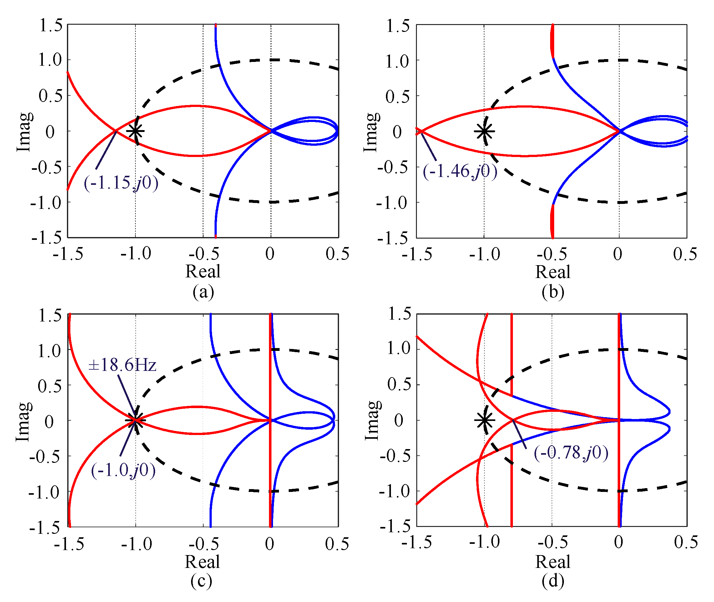
4.2. Stability Analysis Based on Generalized Nyquist Criterion

The GNC is a reliable method for the determination of stability based on the impedance model [23,24,25]. Based on the small-signal analysis developed in Section 3.1, the unified admittance model Yc(s) can be derived. Thus, Yc(s)Zg(s) is adopted to evaluate system stability.
For a more effective comparison, the GNC results for PLL and SOGI-PLL with a bandwidth of 25 Hz are described in Figure 17a,b. It can be detected that their GNC curves cross at (−1.15, j0) and (−1.46, j0), which suggests that GCCs with PLL and SOGI-PLL are terribly unstable. In addition, the GNC results with PI-APS are shown in Figure 17c, where the GNC curves cross at (−1, j0), indicating that the phase margin of the system is 0°. The GCC is in a critical stability state. The frequencies at the intersection of the two curves and the negative real axis are ±18.6 Hz, which is equivalent to 18.6 Hz and 81.4 Hz in the αβ frame. When the GCC is synchronized with the voltage of the PCC by adopting DP-APS, the stability of the GCC is enhanced. As shown in Figure 17d, the GNC curves cross the real axis at (−0.78, j0), which shows that the phase margin required to stabilize the system is sufficient.
Considering what has been discussed above, the dynamic performance and stability analysis are summarized in Table 3. Compared with PLL, SOGI-PLL and PI-APS, DP-APS can effectively mitigate the gain overshoot during the angle tracking process without compromising the dynamic performance, which is beneficial for system stability enhancement.

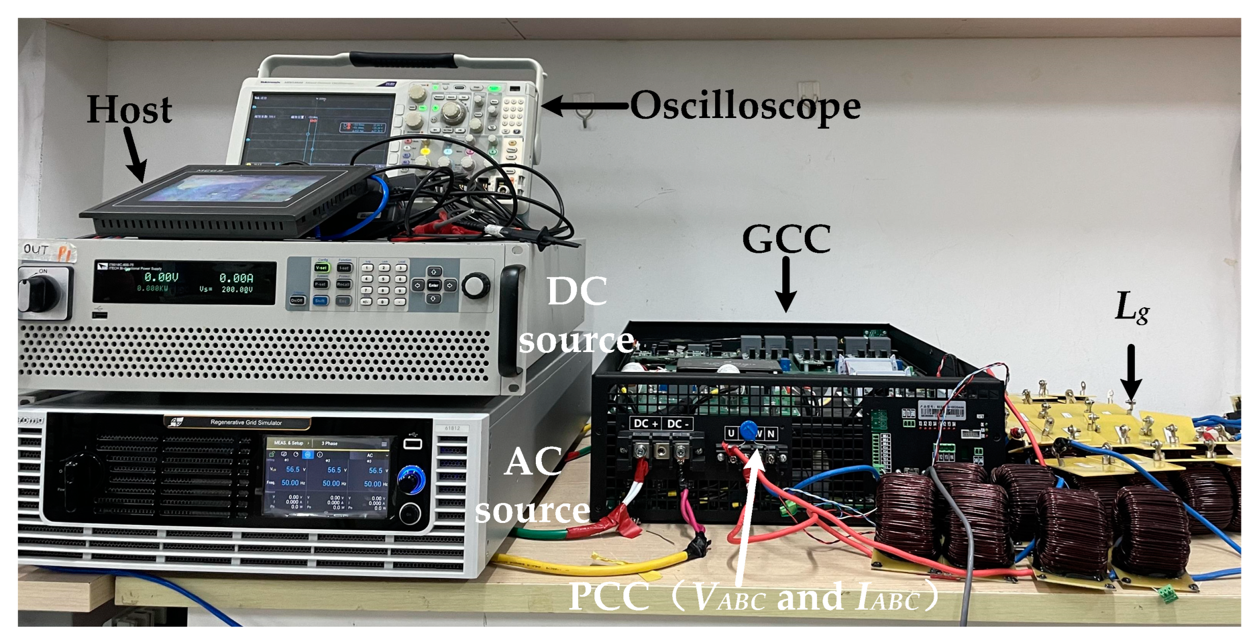
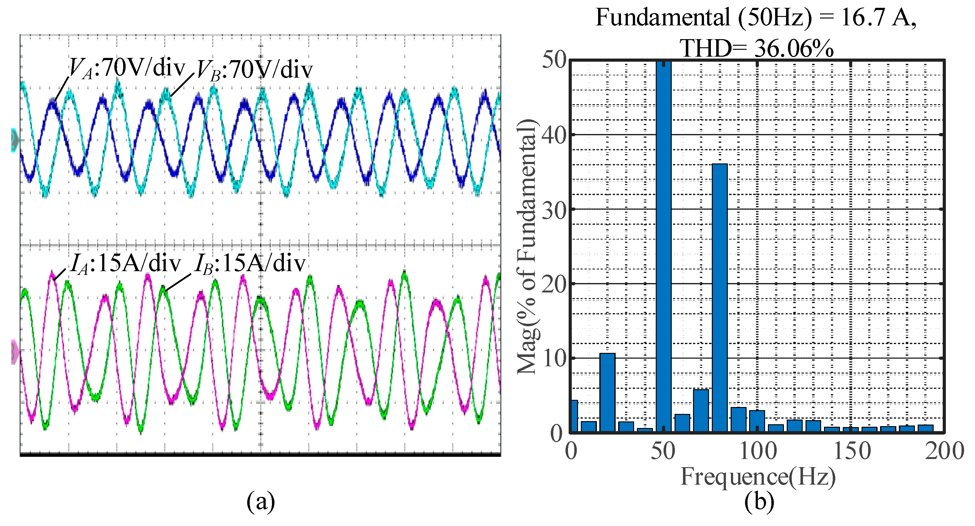
5. Experimental Verification

The experimental validation is conducted on a 2 kVA GCC platform consisting of a DC source, an AC source, a host, an oscilloscope, a GCC, and Lg, as shown in Figure 18. VABC and IABC represent the phase voltage and phase current at the PCC, respectively.
Figure 19a depicts the experimental results of the GCC with PI-APS when SCR = 1.8 P* = 1.0 p.u. and Q* = 0.0 p.u. As can be seen, oscillations in phase voltages (VA, VB) and phase currents (IA, IB) occur, which indicates that the GCC is in a critical steady state. The FFT analysis results for IA are demonstrated in Figure 19b, indicating that the oscillation frequencies are 20 Hz and 80 Hz, which is consistent with the GNC analysis results displayed in Figure 17c.
When PI-APS is replaced with DP-APS under the same operating conditions, the detailed waveforms for the GCC employing DP-APS are shown in Figure 20a, where VA, VB, IA and IB are stable without oscillations. In addition, the FFT analysis is performed on the detailed waveforms of IA, the results of which are described in Figure 20b. It is demonstrated that oscillations at 20 Hz and 80 Hz are effectively restrained, validating the correctness of the GNC analysis results in Figure 17d.
To verify the robustness of DP-APS, the operating condition of an unbalanced grid (VA = 0.95 p.u.) is added to the experimental validation, the results of which are shown in Figure 21. The results shown in Figure 21a demonstrate that DP-APS can stabilize the GCC under an unbalanced grid. Moreover, the FFT analysis of IA shown in Figure 21b indicates that the stability of the system is guaranteed, although a few 150 Hz current harmonics are introduced by the unbalanced grid.
In addition, to further examine the robustness of DP-APS, the SCR is increased from 1.8 to 10 to validate the adaptability of DP-APS to the grid strength, the experimental results of which are shown in Figure 22a. Meanwhile, the FFT analysis of IA is carried out, the results of which are shown in Figure 22b. It is demonstrated that the DP-APS is stable even under a stiff grid.
Based on the above experimental results, the theoretical and mechanistic analyses are verified. Moreover, the effectiveness of DP-APS in strengthening the stability of GCCs under a weak grid is also confirmed.

6. Conclusions

In this paper, the mechanism for the production of static angular error in GCCs employing APS is analyzed, revealing that it is closely associated with the active power current, leading to a non-zero q-axis voltage at the PCC. Then, in an intuitive analysis, closed-loop SISO models of GCCs employing different SUs are developed in this paper, which reveals that APS with a PI controller suffers from stability issues while eliminating static angular errors. This instability is a result of the gain overshoot introduced by the PI controller. Therefore, a composite direct damping controller is derived in this paper to achieve the elimination of the static angular error while strengthening system stability under a weak grid. In addition, the proposed damping controller implemented in the SU is isolated from VCC, which leaves the decoupling control of active and reactive power uncompromised. Finally, the experimental results verify the effectiveness of the proposed composite direct damping controller and the correctness of the mechanistic analysis performed in this paper. Although it can effectively enhance the stability of a system in a weak network, there are slight complexities to consider. Thus, future research will focus on simplifying the structure of DP-APS to make it easier to implement while guaranteeing stability enhancement for GCCs under a weak grid.

Author Contributions

Writing—original draft, T.Z.; Writing—review & editing, C.W.; Supervision, Y.W. All authors have read and agreed to the published version of the manuscript.

Funding

This research received no external funding.

Data Availability Statement

Data are contained within the article.

Conflicts of Interest

The authors declare no conflict of interest.

References

  1. Lorenzen, S.L.; Nielsen, A.B.; Bede, L. Control of a grid-connected converter during weak grid conditions. In Proceedings of the 2016 IEEE 7th International Symposium on Power Electronics for Distributed Generation Systems (PEDG), Vancouver, BC, Canada, 27–30 June 2016; pp. 1–6. [Google Scholar] [CrossRef]
  2. Egea-Alvarez, A.; Barker, C.; Hassan, F.; Gomis-Bellmunt, O. Capability curves of a VSC-HVDC connected to a weak AC grid considering stability and power limits. In Proceedings of the 11th IET International Conference on AC and DC Power Transmission, Birmingham, UK, 10–12 February 2015; pp. 1–5. [Google Scholar] [CrossRef]
  3. Aghazadeh, A.; Davari, M.; Nafisi, H.; Blaabjerg, F. Grid Integration of a Dual Two-Level Voltage-Source Inverter Considering Grid Impedance and Phase-Locked Loop. IEEE J. Emerg. Sel. Top. Power Electron. 2021, 9, 401–422. [Google Scholar] [CrossRef]
  4. Harnefors, L.; Bongiorno, M.; Lundberg, S. Input-Admittance Calculation and Shaping for Controlled Voltage-Source Converters. IEEE Trans. Ind. Electron. 2007, 54, 3323–3334. [Google Scholar] [CrossRef]
  5. Wen, B.; Boroyevich, D.; Burgos, R.; Mattavelli, P.; Shen, Z. Analysis of D-Q Small-Signal Impedance of Grid-Tied Inverters. IEEE Trans. Power Electron. 2016, 31, 675–687. [Google Scholar] [CrossRef]
  6. Cespedes, M.; Sun, J. Adaptive Control of Grid-Connected Inverters Based on Online Grid Impedance Measurements. IEEE Trans. Sustain. Energy 2014, 5, 516–523. [Google Scholar] [CrossRef]
  7. Midtsund, T.; Suul, J.A.; Undeland, T. Evaluation of current controller performance and stability for voltage source converters connected to a weak grid. In Proceedings of the 2nd International Symposium on Power Electronics for Distributed Generation Systems, Hefei, China, 16–18 June 2010; pp. 382–388. [Google Scholar] [CrossRef]
  8. Zhu, D.; Zhou, S.; Zou, X.; Kang, Y. Improved Design of PLL Controller for LCL-Type Grid-Connected Converter in Weak Grid. IEEE Trans. Power Electron. 2020, 35, 4715–4727. [Google Scholar] [CrossRef]
  9. Li, X.; Lin, H. A Design Method of Phase-Locked Loop for Grid-Connected Converters Considering the Influence of Current Loops in Weak Grid. IEEE J. Emerg. Sel. Top. Power Electron. 2020, 8, 2420–2429. [Google Scholar] [CrossRef]
  10. Wu, X.; Li, X.; Yuan, X.; Geng, Y. Grid Harmonics Suppression Scheme for LCL-Type Grid-Connected Inverters Based on Output Admittance Revision. IEEE Trans. Sustain. Energy 2015, 6, 411–421. [Google Scholar] [CrossRef]
  11. Yi, H.; Wang, X.; Blaabjerg, F.; Zhuo, F. Impedance Analysis of SOGI-FLL-Based Grid Synchronization. IEEE Trans. Power Electron. 2017, 32, 7409–7413. [Google Scholar] [CrossRef]
  12. Zhang, Y.; Yang, X.; Zhang, Z. High-Efficiency Broadband Electroacoustic Energy Conversion Using Non-Foster-Inspired Circuit and Adaptively Switched Capacitor. IEEE Trans. Ind. Electron. 2025, 1–12. [Google Scholar] [CrossRef]
  13. Huang, L.; Wu, C.; Zhou, D.; Blaabjerg, F. A Double-PLLs-Based Impedance Reshaping Method for Extending Stability Range of Grid-Following Inverter Under Weak Grid. IEEE Trans. Power Electron. 2022, 37, 4091–4104. [Google Scholar] [CrossRef]
  14. Gui, Y.; Wang, X.; Blaabjerg, F.; Pan, D. Control of Grid-Connected Voltage-Source Converters: The Relationship Between Direct-Power Control and Vector-Current Control. IEEE Ind. Electron. Mag. 2019, 13, 31–40. [Google Scholar] [CrossRef]
  15. Gui, Y.; Wang, X.; Blaabjerg, F. Vector Current Control Derived from Direct Power Control for Grid-Connected Inverters. IEEE Trans. Power Electron. 2019, 34, 9224–9235. [Google Scholar] [CrossRef]
  16. Gui, Y.; Kim, C.; Chung, C.C.; Guerrero, J.M.; Guan, Y.; Vasquez, J.C. Improved Direct Power Control for Grid-Connected Voltage Source Converters. IEEE Trans. Ind. Electron. 2018, 65, 8041–8051. [Google Scholar] [CrossRef]
  17. Wu, C.; Xiong, X.; Blaabjerg, F. Impedance Analysis of Voltage Source Converter Based on Voltage Modulated Matrix. In Proceedings of the 2021 IEEE Energy Conversion Congress and Exposition (ECCE), Vancouver, BC, Canada, 10–14 October 2021; pp. 887–892. [Google Scholar] [CrossRef]
  18. Zhang, L.; Harnefors, L.; Nee, H. Power-Synchronization Control of Grid-Connected Voltage-Source Converters. IEEE Trans. Power Syst. 2010, 25, 809–820. [Google Scholar] [CrossRef]
  19. Bahrani, B. Power-Synchronized Grid-Following Inverter Without a Phase-Locked Loop. IEEE Access 2021, 9, 112163–112176. [Google Scholar] [CrossRef]
  20. Mansour, M.Z.; Ravanji, M.H.; Karimi, A.; Bahrani, B. Linear Parameter-Varying Control of a Power-Synchronized Grid-Following Inverter. IEEE J. Emerg. Sel. Top. Power Electron. 2022, 10, 2547–2558. [Google Scholar] [CrossRef]
  21. Gu, Y.; Green, T.C. Power System Stability with a High Penetration of Inverter-Based Resources. Proc. IEEE 2022, 111, 832–853. [Google Scholar] [CrossRef]
  22. Asensio, A.P.; Gómez, S.A.; Rodriguez-Amenedo, J.L.; Cardiel-Álvarez, M.Á. Reactive Power Synchronization Method for Voltage-Sourced Converters. IEEE Trans. Sustain. Energy 2019, 10, 1430–1438. [Google Scholar] [CrossRef]
  23. Sun, Z.; Sun, Y.; Lin, J.; Xie, S.; Han, H.; Wu, Z. Impedance Modeling and Stability Analysis of Single-Phase LCL-type Grid-Connected VSC Based on Harmonic Linearization. In Proceedings of the 2021 IEEE 12th Energy Conversion Congress & Exposition—Asia (ECCE-Asia), Singapore, 24–27 May 2021; pp. 2143–2148. [Google Scholar] [CrossRef]
  24. Huang, L.; Wu, C.; Zhou, D.; Blaabjerg, F. A Simplified SISO Small-Signal Model for Analyzing Instability Mechanism of Grid-Forming Inverter under Stronger Grid. In Proceedings of the 2021 IEEE 22nd Workshop on Control and Modelling of Power Electronics (COMPEL), Cartagena, Colombia, 2–5 November 2021; pp. 1–6. [Google Scholar] [CrossRef]
  25. Liao, Y.; Wang, X.; Liu, F.; Xin, K.; Liu, Y. Sub-Synchronous Control Interaction in Grid-Forming VSCs with Droop Control. In Proceedings of the 2019 4th IEEE Workshop on the Electronic Grid (eGRID), Xiamen, China, 11–14 November 2019; pp. 1–6. [Google Scholar] [CrossRef]
Figure 1. The topology and structure of the GCC employing VCC and APS.
Electronics 14 01781 g001
Figure 2. The equivalent circuit between Vo and Vg.
Electronics 14 01781 g002
Figure 3. Phasor diagram of Vo, Io, and Vg with SCR = 1.8 in typical operating conditions: (a) Iod = 1.0 p.u. and Ioq = 0 p.u.; (b) Iod = 0 p.u. and Ioq = −1.0 p.u.
Electronics 14 01781 g003
Figure 4. Variation trend of θpcc with SCR = 1.8 when Iod and Ioq change from −1.0 p.u. to 1.0 p.u: (a) 3D view; (b) top view.
Electronics 14 01781 g004
Figure 5. Variation trend of Voq with SCR = 1.8 when Iod and Ioq change from −1.0 p.u. to 1.0 p.u: (a) 3D view; (b) top view.
Electronics 14 01781 g005
Figure 6. The structure of the synchronization unit defined as PI-APS for comparison with the composite direct damping controller proposed in this paper.
Electronics 14 01781 g006
Figure 7. The mechanism of the impact generated by Δθpcc on Δθs.
Electronics 14 01781 g007
Figure 8. Structure of the small-signal model of conventional PLL.
Electronics 14 01781 g008
Figure 9. Structure of the small-signal model of conventional SOGI-PLL.
Electronics 14 01781 g009
Figure 10. Bode diagrams of closed-loop SISO models when P* varies from 0.4 p.u. to 1.0 p.u.: (a) GAPS(s); (b) GPI-APS(s).
Electronics 14 01781 g010
Figure 11. Small-signal model of VCC.
Electronics 14 01781 g011
Figure 12. Small-signal model of the ideal damping controller implemented in the q-axis current control loop.
Electronics 14 01781 g012
Figure 13. Small-signal model of the practical proposed composite damping controller implemented in the synchronization unit.
Electronics 14 01781 g013
Figure 14. Flowchart of the parameter design process for DP-APS.
Electronics 14 01781 g014
Figure 15. Frequency scan validation and comparative analysis of bode diagrams for GPLL(s), GSOGI-PLL(s), GPI-APS(s) and GDP-APS(s).
Electronics 14 01781 g015
Figure 16. Dynamic performance of the GCC employing PI-APS and DP-APS when the grid angle jumps 0.25 p.u. (−π/2 rad).
Electronics 14 01781 g016
Figure 17. Generalized Nyquist diagrams under the conditions of SCR = 1.8, P* = 1.0 p.u. and Q* = 0 p.u.: (a) PLL, (b) SOGI-PLL, (c) PI-APS and (d) DP-APS.
Electronics 14 01781 g017
Figure 18. Structure of the 2 kVA GCC platform.
Electronics 14 01781 g018
Figure 19. Experimental results for the GCC employing PI-APS when SCR = 1.8, P* = 1.0 p.u. and Q* = 0.0 p.u.: (a) output voltage and current waveform at PCC; (b) FFT analysis results for IA.
Electronics 14 01781 g019
Figure 20. Experimental results for the GCC employing DP-APS when SCR = 1.8, P* = 1.0 p.u. and Q* = 0.0 p.u.: (a) output voltage and current waveform at PCC; (b) FFT analysis results for IA.
Electronics 14 01781 g020
Figure 21. Experimental results of the GCC employing DP-APS with an unbalanced grid (VA = 0.95 p.u.) when SCR = 1.8, P* = 1.0 p.u. and Q* = 0.0 p.u.: (a) output voltage and current waveform at PCC; (b) FFT analysis results for IA.
Electronics 14 01781 g021
Figure 22. Experimental results of the GCC employing DP-APS when SCR = 10.0, P* = 1.0 p.u. and Q* = 0.0 p.u.: (a) output voltage and current waveform at PCC; (b) FFT analysis results for IA.
Electronics 14 01781 g022
Table 1. Detailed parameters of the GCC system.
NameValue
GridGrid voltage (peak value), VgN80 V
Grid frequency, ω0100π rad/s
Short circuit ratio, SCR1.8
R/X ratio of grid impedance, Rg/Xg0.01
Grid impedance, Rg, Lg0.0267 Ω, 8.5 mH
GCCRated power of inverter, SN2000 VA
Rated voltage (peak value), VoN80 V
Rated current (peak value), IoN16.7 A
DC-bus voltage, Vdc300 V
Switching frequency, fsw = 1/Tsw20 kHz
Filter inductor impedance, Rf, Lf,0.1 Ω, 1 mH
The gain of active power synchronization, KAPS0.008
The bandwidth of the current PI controller, ωc2576 rad/s
Parameters of the current PI controller, KpI = ωcLf, KiI = ωc2Lf/102.58, 663.6
Table 2. Detailed parameters of PLL, SOGI-PLL, PI-APS and DP-APS.
NameValue
PLLKpPLL1 and KiPLL11.35 and 72.8
SOGI-PLLKSOGI, ωSOGI,KpPLL2 and KiPLL20.7, 314 rad/s, 2.48 and 246.5
PI-APSKAPS, KpAux1 and KiAux10.008, 1.64 and 43.09
DP-APSKAPS, Rv, ωLPF and KiAux20.008, 4.05 Ω, 314 rad/s and 43.69
Table 3. Stability and overshoot percentage of GCCs with different synchronization units.
Name of Synchronization Unit Phase Margin Overshoot Percentage
PLLUnstable30%
SOGI-PLLUnstable27%
PI-APSCritically stable15%
DP-APSStable6%
Disclaimer/Publisher’s Note: The statements, opinions and data contained in all publications are solely those of the individual author(s) and contributor(s) and not of MDPI and/or the editor(s). MDPI and/or the editor(s) disclaim responsibility for any injury to people or property resulting from any ideas, methods, instructions or products referred to in the content.

