Article

A Wideband Orbital Angular Momentum Antenna Array Design for Wireless Communication

1
National Key Laboratory of Electromagnetic Energy, Naval University of Engineering, Wuhan 430033, China
2
School of Information and Communications Engineering, Xi’an Jiaotong University, Xi’an 710049, China
*
Author to whom correspondence should be addressed.
Electronics 2025, 14(8), 1601; https://doi.org/10.3390/electronics14081601
Submission received: 13 February 2025 / Revised: 29 March 2025 / Accepted: 30 March 2025 / Published: 15 April 2025

Abstract

:
In this paper, a wideband OAM antenna array for wireless communication is proposed, which has a wide impedance bandwidth and can cover the S-C band with a relative bandwidth of 61.58%. The measured gain can reach 7.81 dBi and the radiation efficiency can reach 74.7%. Compared with similar antennas, the antenna array has a metal back cavity as the supporting structure, which further improves the structural stability of the array. The array adopts Z-shaped parasitic radiation units, a ring-shaped stepped metal reflection back cavity, and other structures. These can be verified to improve the performance of the array after design analysis and testing. In addition, the performance enhancement of a conventional Wilkinson divider by adding the S-shaped parasitic radiation patch is analysed by parameter scanning. The array is robust, simple to process, and easy to integrate. It can maximise its value in the crowded retrofit space of wireless antennas.

1. Introduction

Orbital angular momentum (OAM) antennas have received a lot of attention from researchers in recent years. This is due to their theoretically infinite number of modes. The modes are orthogonal to each other and do not interfere with each other [1,2,3,4,5,6,7,8]. This feature can not only effectively solve the problem of scarce spectrum resources but can also improve the anti-interference capability of the communication system, which contributes to confidential communications [9,10,11,12,13]. For example, Hui et al. achieved simultaneous transmission of HD video and square-wave signals using two OAM modes’ multiplexed transmission in the 60 GHz band, achieving a 4 Gbps transmission rate and 1.4 m transmission distance [14]. Liu et al. adopted an electromagnetic eddy current enhanced imaging method based on double-coupled OAM beams and fractional-order OAM beams, which significantly improved the imaging resolution and efficiency of communication detection [15,16]. In addition, Wang et al. combined OAM beam and strip SAR techniques to obtain a two-dimensional image of the target using a modified range-doppler (RD) algorithm [17].
Based on the existing studies, there are numerous types of antennas that can generate OAM modes, such as helical antennas [18], loop arrays [19], phased arrays [20], Transmitarrays and Reflectarrays [21], and cross-dipole antennas that can generate broadband circular polarisation [22]. Among them, the helical antenna has a wide bandwidth, low profile, and stable broadband radiation characteristics [23]. However, its feed structure is complex, requires high processing accuracy, and is not easy to integrate on a large scale. A loop array is easy to realise and simple in principle, but it requires a complex feed network and larger calibre [24]. A phased array is flexible and easy to integrate but is the costliest to implement [6,25]. The artificial ultra-surface needs added antennas as a feed source, the location of the feed source has high requirements, and it is not easy to integrate it into the airborne scanning antenna [26,27,28,29,30]. In recent years, the cross-dipole antenna has attracted a lot of attention and interest from the academic community because of its many advantages, such as high-gain directional radiation, a wide bandwidth and compact structure, and easy processing and feeding [31].
Current research on OAM antennas focuses on improving their multimodal, gain, and communication performance [21,32,33]. With the continuous evolution of communication environments, the signal interference and attenuation in the communication process have become more complex, which puts higher requirements on the design of communication systems. The OAM antenna is characterised by having an orbital angular momentum and a helical wavefront structure [15]. As a result, during communication detection, the echo signal contains information about the azimuthal direction of the target, providing additional azimuthal resolution. The ability to achieve high-resolution imaging is critical for accurate target identification and classification [16,17]. In order to explore more application prospects of OAM antennas, this paper proposes an S/C-band OAM antenna array with compact topology. It also meets the currently growing demand for unmanned aerial vehicle (UAV) control. Unlike a common planar wave antenna, this antenna can generate a spiral wavefront structure to detect the motion characteristics of the target itself. This can be used to further analyse the target’s intent.
In this paper, a dual-band OAM antenna capable of operating simultaneously in the S/C band is generated by changing the excitation pattern of the feed network based on the radiation mechanism of a broadband cross-dipole antenna array (CDAA) combined with parasitic radiation patches as well as an annular step-reflecting metal back cavity. The OAM antenna array proposed in this paper has the characteristics of a wide bandwidth, compact structure, being able to realise dual-band OAM characteristics simultaneously in the S/C band, and adopting a metal shell to increase the stability of the structure, making it suitable for wireless communication and sensing applications.

2. Design Procedure

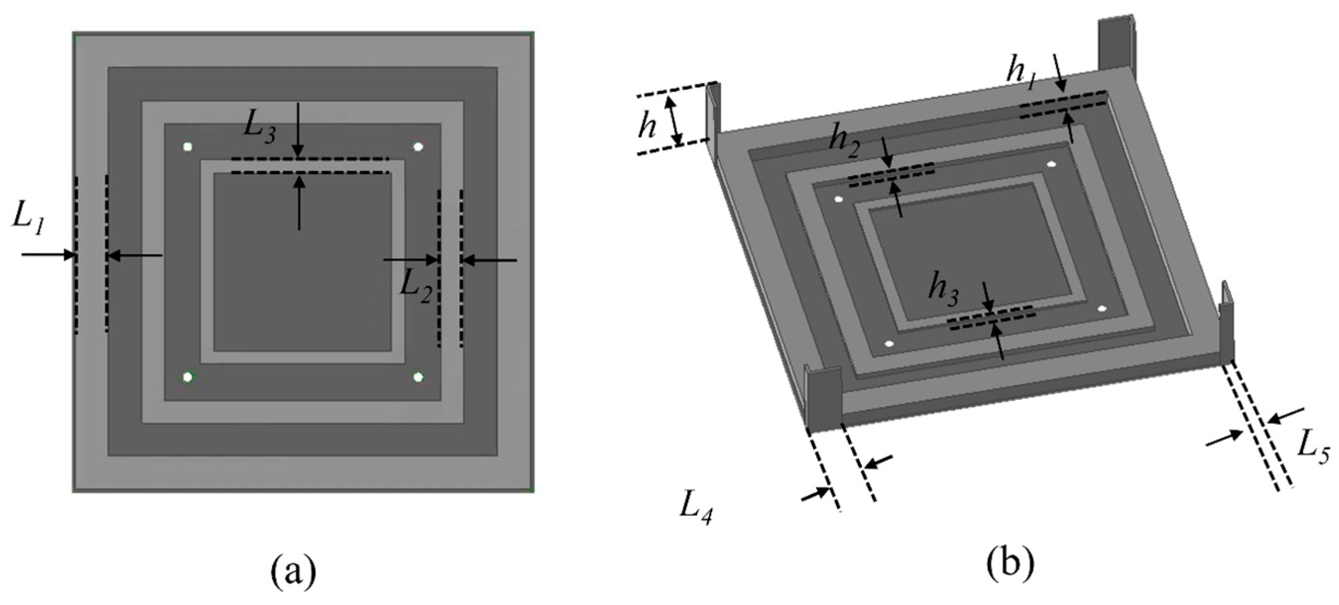
2.1. OAM Antennas Array Design Based on Rotating Cross-Dipoles

The mechanism of the proposed antenna is based on the operating characteristics of the Pancharatnam–Berry (PB) phase, i.e., the 0 to 360° rotation of a circularly polarised (CP) antenna can generate an extra 0 to 360° radiation phase delay. Based on the PB phase, four CP cross-dipole antennas are used to generated 1 mode OAM beam. The rotation angles of the cross-dipole antennas are 0°, 90°, 180°, and 270°; thus, the dipole can be excited with 90° phase delay. Next, to match the radiation bandwidth with the impedance matching band, the top Z-shaped radiator patch and the bottom grooves with different heights are used to optimise the radiation patterns. Finally, the S-shaped parasitic patches are combined with the antenna feeding network, which can help further optimise the operating band of the proposed antenna. The genetic algorithm (GA) in the commercial full-wave simulation software HFSS 2024 R2 is used as the algorithm of the optimisation process.

2.1.1. Broadband Cross-Dipole Rotating Array with Z-Shaped Parasitic Radiation Cells

The CDAA easily realises the broadband OAM radiation characteristics by rotating the elements of the array, and the feed network only needs to meet the requirement of an equal amplitude and phase, which is inspired by [34,35]. Therefore, this paper forms the array by rotating the elements and loads the Z-shaped parasitic radiation unit near the antenna radiator to change the current distribution on the antenna surface and expand the antenna bandwidth.
The basic structure of the CDAA is shown in Figure 1, consisting of eight cross-dipole patches (CDPs) and four Z-like parasitic patches (ZLPPs) on an FR-4 substrate. The relative dielectric constant and loss tangent of the substrate are 4.4 and 0.02, respectively. Its top view is shown in Figure 1a, which is a four-element array formed by sequentially rotating the CDPs and ZLPPs by 90° from the centre of the array. The dimensions of the substrate are 140 mm × 140 mm × 1.6 mm. Its rear side, as shown in Figure 1b, consists of four pairs of mutually separated windmill-like radiating patches made of metallic copper foil in a centrifugally distributed state by rotation. Each pair of windmill-shaped radiating patches has two perpendicular fan-shaped blades. The patches are connected by a 3/4 λg bridge to provide the phase difference required to produce broadband circular polarisation. The fan blade has a radius of 15.51 mm and is connected to the bridge by a rectangular patch with a width of 2.69 mm, the end of which is soldered to the inner core of the coaxial wire.
The front side of the radiator is similar to the back side, which is also composed of four pairs of windmill-shaped radiating patches separated from each other, and two mutually perpendicular fan-shaped blade tips of each pair have the tendency of converging with the fan-shaped blade tips of the neighbouring windmill-shaped radiating patches, but they are not connected. Based on these four pairs of windmill-shaped radiating patches, four Z-shaped parasitic radiating patches are loaded around the radiator to improve the impedance bandwidth of the antenna, which initially forms the basic operation mode of the OAM antenna. The width of the Z-shaped radiator patch is 1.85 mm, the length of the shorter branches at both ends is 14.70 mm and the length of the longer branches in the centre is 34.07 mm. There are four 1.2 mm diameter circular through-holes in the centre of the substrate. With the centre of the array as the origin, the coordinates of these four circular vias are (35 mm, 35 mm, 0 mm), (35 mm, −35 mm, 0 mm), (−35 mm, −35 mm, 0 mm), and (−35 mm, 35 mm, 0 mm). The inner coaxial cable is connected to the metal patches on the front and rear of the radiator through these four circular holes. The sizes of the cross-dipole element are determined by the optimisation procedure. The simulated S-parameters with the different ra and D1 are shown in Figure 1d,e.

2.1.2. Ring Step Metal Reflective Back Cavity

Based on the broadband cross-dipole rotating array with Z-shaped parasitic radiating units of Section 2.1.1, we further propose the use of an annular stepped metal reflective back cavity as the reflective floor structure of the antenna, as shown in Figure 2a,b, which is a schematic of a metal reflective back cavity with a length and width of 140 mm × 140 mm. The performance of the antenna can be improved by using a back-cavity reflector as an additional radiator. The main principle is that when the main radiator is excited, the coupling aperture is formed by the edges of the cavity. The reflection phase varies more at different frequencies for stepped ground than for flat ground. Varying the scan angle also has a significant effect on the phase of the reflection. The impedance bandwidth of the antenna can be increased by using a stepped ground without increasing the profile of the antenna. To verify the feasibility of the ring step metal reflective back cavity, the S-parameter and gain of the antenna with the different layers of the ring cavity are presented in Figure 2c,d. It can be clearly observed that when the number of ring cavities increases, the impedance matching of the antenna continues to slightly improve and the gain continues to increase.
The metal back cavity consists of three metal rings of different heights. The outermost metal ring has four L-shaped metal arms connected to the radiator in the top layer, with the long side of the L-shaped metal arms being 11.09 mm long, the short side being 4.43 mm long, and the height of the arms being 26 mm. The height of the outermost metal ring is 5 mm, and the thickness of the ring is 10 mm; the height of the intermediate metal ring is 2 mm, and the thickness of the ring is 7 mm; the height of the inner metal ring is 1 mm, and the thickness of the ring is 4 mm. The bottom of the metal back cavity is connected by a dielectric substrate of Rogers RO4350, with a thichness of 0.762 mm, and a relative dielectric constant of 3. The bottom of the metal back cavity is separated from the bottom feed network by a dielectric substrate with a thickness of 0.762 mm, a material Rogers RO4350, a dielectric constant of 3.66, and a loss angle tangent of 0.004.

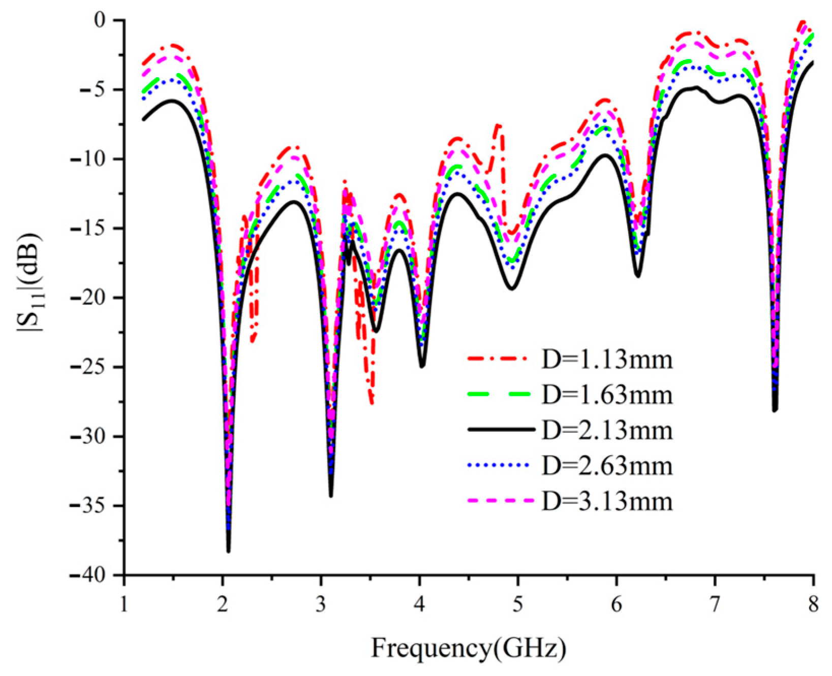
2.2. Bottom Feed Network Design

The structural design is further parametrically simulated using commercial full-wave simulation software HFSS. The bottom feed network consists of two levels of cascaded Wilkinson power dividers, consisting of three isolation resistors of 100 Ω resistance. The isolation resistors maximise the elimination of reflections and interference within the power splitter, ensuring the best possible match between input and output. In addition, six S-shaped parasitic radiation patches have been added around the main feed network to increase design freedom and further improve impedance-matching performance. On this basis, the S-parameter performance of the antenna under different coupling performances is obtained by adjusting the distance between the S-shaped parasitic patches on both sides of the bottom main feed network and the main feed network, which is shown in Figure 3, where the red material is the metal copper foil, the purple one is the isolation resistor, and the azure one is the dielectric substrate. The simulated reflection coefficients of the proposed power divider with different D are shown in Figure 4. The optimum spacing between the parasitic radiation patch and the main feed network, derived from Figure 4, is 2.13 mm. With this spacing, the power divider can achieve optimised impedance matching over a wide range of frequencies. Figure 5 shows the S-parameters of the entire antenna array with this spacing.

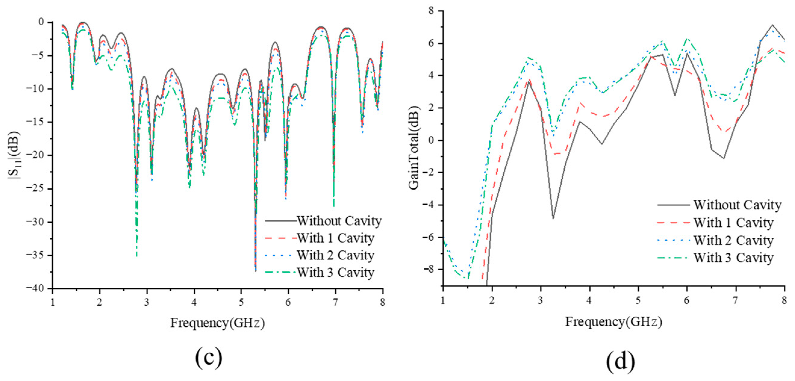
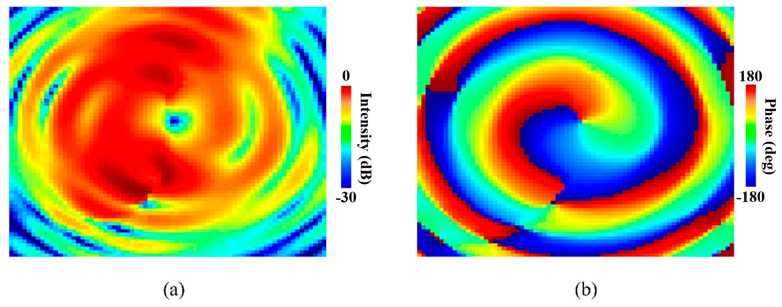
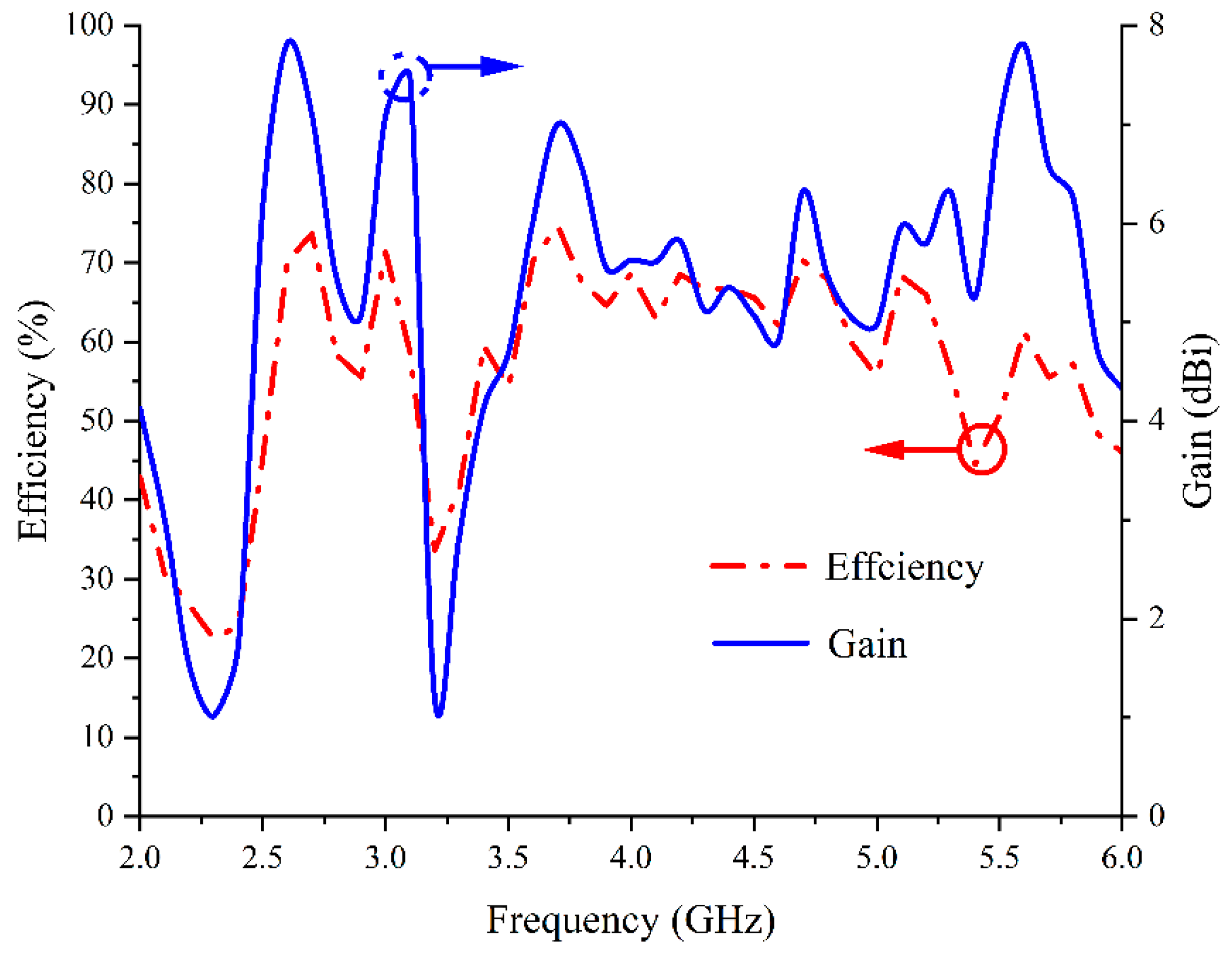
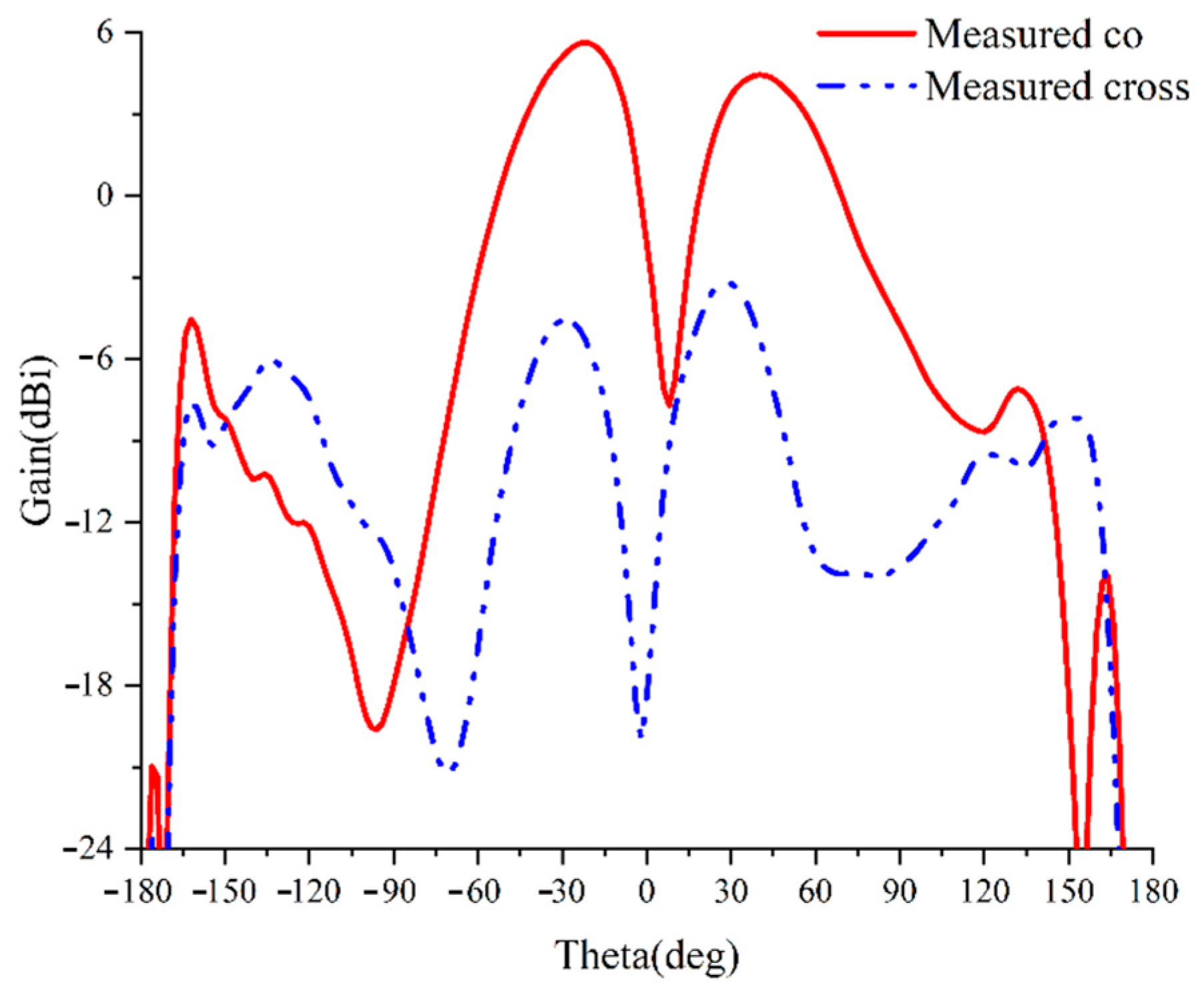
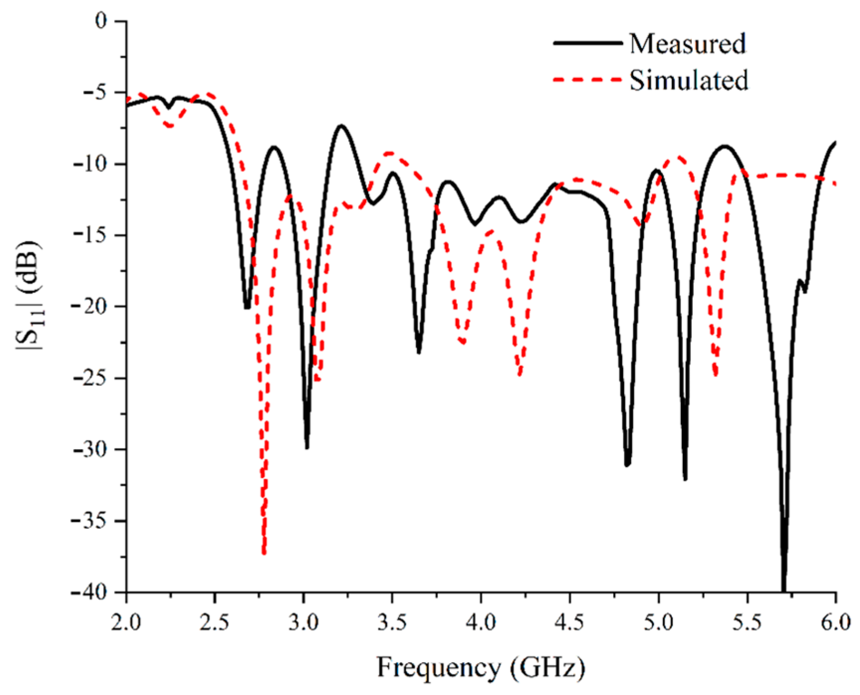
3. Fabrication and Measurement

After parametric analysis, we obtain the optimal antenna simulation model and process the antenna prototype device on this basis. The near-field performance of the antenna is measured using a near-field darkroom, as shown in Figure 6. The measured phase distribution of the near-field amplitude is shown in Figure 7.
In order to quantify the purity of the OAM beams, Fourier transform is used to decompose the OAM beams into different OAM modes [36,37]. The decomposition method is shown in Equations (1) and (2), where Al is the Fourier coefficient of the OAM beams with mode number l, ψ(φ) is the discrete E-field distribution along the circumference of the OAM beam’s null location, and the E-field distribution is the maximum value along the radius direction.
A l = 1 2 π 0 2 π ψ ( φ ) e j l φ d φ
ψ ( φ ) = l = + A l e j l φ
In the purity calculation, the OAM beams with mode numbers l = −3 to 3 are considered. The purity of the OAM mode l is defined as follows:
P u r i t y ( l ) = A l i = 3 3 A i
Figure 8 shows the mode purity of the measured near field. As can be seen from the figure, the number of modes with l = 1 accounts for more than 70% of the weight, confirming that the feed-phase difference of 90° apart has successfully motivated the mode.
The 3D radiation pattern of the antenna is shown in Figure 9. The radiation null can clearly be observed in the broadside direction, proving the achievement of the OAM beams within the impedance-matching bandwidth of the proposed antenna. The variation in the measured maximum gain and radiation efficiency with frequency is shown in Figure 10. From Figure 10, it can be seen that the maximum radiation efficiency of the antenna can be up to 74.7% and the maximum gain can be up to 7.81 dBi, which explains the performance of the antenna to some extent. Figure 11 shows the far-field orientation of this antenna at 3 GHz. The beam is cut in the xoz plane (phi = 0°), and the corresponding coordinate system is marked in Figure 1. Due to the 90° rotational symmetry of the antenna structure, only one cross-sectional result is presented in this paper, as the result of the orthogonal cross-section is nearly identical. It can be observed that the left-hand circular polarisation main component at 3 GHz is 12 dB higher than the cross-component, which presents a vortex characteristic.
Then, the S-parameters of the antenna are measured using an Agilent vector network analyser (E8363B). The vector network analyser is manufactured in Agilent Technologies, originating from the USA. The measured results are shown in Figure 12. When comparing test results with the S-parameters obtained from simulation, the simulation results indicate that the frequency ranges of the antenna with |S11| lower than −10 dB are 2.65 GHz~3.42 GHz and 3.58 GHz~5.03 GHz, while the measured results show that the antenna with |S11| lower than −10 dB are 2.58 GHz~2.77 GHz, 2.88 GHz~3.14 GHz, and 3.31 GHz~5.28 GHz. The relative bandwidth is 61.58%. This shows that the employed ring step metal reflective back cavity as well as parasitic radiation patches are effective. The discrepancy between the simulated and measured refection coefficient is introduced by the four coaxial cables which are used to connect the dipoles and the feeding network. During the fabrication procedure, it is difficult to achieve coaxial cables with four segments of exactly equal length, due to manual manufacturing errors. The different lengths of the coaxial cables will generate reflection fields with different phase delays, thus resulting in the slight offset in the reflection coefficients.
To highlight the advantages of the proposed design, several reported OAM antennas are compared with this OAM antenna, as shown in Table 1. The results show that the cross-dipole designs in this paper have an excellent peak gain, low profile, and high impedance bandwidth.

4. Conclusions

This paper has investigated the wireless OAM antenna that can be applied for S and C bands. The antenna has broadband and high gain characteristics, its bandwidth lies in the S-C band, the far-field and near-field performance is better, and it adopts a metal back cavity as the support structure, so that the overall structural stability is higher. It can be applied to the wireless environment. Its compact structure and high performance make it valuable for wireless communication and sensing applications.

Author Contributions

Methodology, J.Z.; validation, Z.Y. and Y.C.; formal analysis, Z.Y. and J.Z.; investigation, Z.Y.; writing—original draft preparation, Z.Y. and K.Z.; writing—review and editing, Z.Y., K.Z. and S.Y.; visualisation, H.L. and Y.C.; supervision, J.Z. and S.Y. All authors have read and agreed to the published version of the manuscript.

Funding

This work is supported in part by the Young Elite Scientists Sponsorship Program, under Grant 2021-JCJQ-QT-009, and in part by the School Independent Research and Development Projects (202350E040).

Data Availability Statement

The data that support the findings of this study are available from the corresponding author upon reasonable request.

Conflicts of Interest

The authors declare no conflicts of interest.

References

  1. Li, H.; Kang, L.; Wei, F.; Cai, Y.-M.; Yin, Y.-Z. A low-profile dual-polarized microstrip antenna array for dual-mode OAM applications. IEEE Antennas Wirel. Propag. Lett. 2017, 16, 3022–3025. [Google Scholar]
  2. Liu, D.; Gui, L.; Zhang, Z.; Chen, H.; Song, G.; Jiang, T. Multiplexed OAM wave communication with two-OAM-mode antenna system. IEEE Access 2019, 7, 4160–4166. [Google Scholar] [CrossRef]
  3. Lei, X.Y.; Cheng, Y.J. High-efficiency and high-polarization separation reflectarray element for OAM-folded antenna application. IEEE Antennas Wirel. Propag. Lett. 2017, 16, 1357–1360. [Google Scholar] [CrossRef]
  4. Li, W.; Zhu, J.; Liu, Y.; Zhang, B.; Liu, Y.; Liu, Q.H. Realization of third-order OAM mode using ring patch antenna. IEEE Trans. Antennas Propag. 2020, 68, 7607–7611. [Google Scholar] [CrossRef]
  5. Li, W.; Zhang, L.; Yang, S.; Zhuo, K.; Ye, L.; Liu, Q.H. A reconfigurable second-Order OAM patch antenna with simple structure. IEEE Antennas Wirel. Propag. Lett. 2020, 19, 1531–1535. [Google Scholar] [CrossRef]
  6. Feng, P.-Y.; Qu, S.-W.; Yang, S. OAM-generating transmitarray antenna with circular phased array antenna feed. IEEE Trans. Antennas Propag. 2020, 68, 4540–4548. [Google Scholar] [CrossRef]
  7. Wu, J.; Fan, M.; Lu, X.; Hu, J.; Xie, G.; Huang, Z. Circularly polarized and linear polarized mode multiplexing OAM antenna using sequentially rotated technique. IEEE Antennas Wirel. Propag. Lett. 2024, 23, 1261–1265. [Google Scholar] [CrossRef]
  8. Qin, F.; Li, L.; Liu, Y.; Cheng, W.; Zhang, H. A four-mode OAM antenna array with equal divergence angle. IEEE Antennas Wirel. Propag. Lett. 2019, 18, 1941–1945. [Google Scholar] [CrossRef]
  9. Xu, J.; Zhao, M.; Zhang, R.; Lei, M.; Gao, X.; Huang, S.; Bi, K. A wideband F-Shaped microstrip antenna. IEEE Antennas Wirel. Propag. Lett. 2017, 16, 829–832. [Google Scholar] [CrossRef]
  10. Khan, M.I.W.; Woo, J.; Yi, X.; Ibrahim, M.I.; Yazicigil, R.T.; Chandrakasan, A.P.; Han, R. A 0.31-THz orbital-angular-momentum (OAM) wave transceiver in CMOS with bits-to-OAM mode mapping. IEEE J. Solid-State Circuits 2022, 57, 1344–1357. [Google Scholar] [CrossRef]
  11. Chen, R.; Zhou, H.; Moretti, M.; Wang, X.; Li, J. Orbital angular momentum waves: Generation, detection, and emerging applications. IEEE Commun. Surv. 2020, 22, 840–868. [Google Scholar] [CrossRef]
  12. Liu, K.; Cheng, Y.; Li, X.; Gao, Y. Microwave sensing technology using orbital angular momentum overview of its advantages. IEEE Veh. Technol. Mag. 2019, 14, 112–118. [Google Scholar]
  13. Bu, X.; Zhang, Z.; Chen, L.; Liang, X.; Tang, H.; Wang, X. Implementation of vortex electromagnetic waves high-resolution synthetic aperture radar imaging. IEEE Antennas Wirel. Propag. Lett. 2018, 17, 764–767. [Google Scholar]
  14. Hui, X.; Zheng, S.; Chen, Y.; Hu, Y.; Jin, X.; Chi, H.; Zhang, X. Multiplexed millimeter wave communication with dual orbital angular momentum (OAM) mode antennas. Sci. Rep. 2015, 5, 10148. [Google Scholar]
  15. Liu, H.; Liu, K.; Cheng, Y.; Wang, H. Microwave vortex imaging based on dual coupled OAM beams. IEEE Sens. J. 2020, 20, 806–815. [Google Scholar]
  16. Liu, H.; Wang, Y.; Wang, J.; Liu, K.; Wang, H. Electromagnetic vortex enhanced imaging using fractional OAM beams. IEEE Antennas Wirel. Propag. Lett. 2021, 20, 948–952. [Google Scholar]
  17. Wang, J.; Liu, K.; Cheng, Y.; Wang, H. Vortex SAR imaging method based on OAM beams design. IEEE Sens. J. 2019, 19, 11873–11879. [Google Scholar] [CrossRef]
  18. Yuan, T.; Cheng, Y.; Wang, H.; Qin, Y. Generation of OAM radio beams with modified uniform circular array antenna. Electron. Lett. 2016, 52, 19896–19897. [Google Scholar]
  19. Saitou, A.; Uchida, K.; Kitayama, K.; Ishikawa, R.; Honjo, K. Analysis of beamforming for OAM communication using loop antenna arrays and paraboloids. IEICE Trans. Commun. 2024, E107B, 776–784. [Google Scholar]
  20. Thidé, B.; Then, H.; Sjöholm, J.; Palmer, K.; Bergman, J.; Carozzi, T.D.; Istomin, Y.N.; Ibragimov, N.H.; Khamitova, R. Utilization of photon orbital angular momentum in the low-frequency radio domain. Phys. Rev. Lett. 2007, 99, 087701. [Google Scholar] [CrossRef]
  21. Qin, F.; Zeng, L.; Liu, S.; Gu, C.; Liu, X.; Zhang, H. Dual-mode high-gain OAM array based on nested metasurface with simplified feeding network. IEEE Antennas Wirel. Propag. Lett. 2024, 23, 59–63. [Google Scholar] [CrossRef]
  22. Yang, Z.; Bao, J.; Li, W.; Liu, B.; Wang, H.; Kang, L.; Shi, X.W. Broadband circularly polarized antenna with non-planar reflector. IEEE Access 2020, 8, 164407–164413. [Google Scholar]
  23. Shen, F.; Mu, J.; Guo, K.; Wang, S.; Guo, Z. Generation of continuously variable-mode vortex electromagnetic waves with three-dimensional helical antenna. IEEE Antennas Wirel. Propag. Lett. 2019, 18, 1091–1095. [Google Scholar]
  24. Yuan, T.; Cheng, Y.; Wang, H.; Qin, Y. Mode characteristics of vortical radio wave generated by circular phased array: Theoretical and experimental results. IEEE Trans. Antennas Propag. 2017, 65, 688–695. [Google Scholar]
  25. Liu, K.; Liu, H.; Qin, Y.; Cheng, Y.; Wang, S.; Li, X.; Wang, H. Generation of OAM beams using phased array in the microwave band. IEEE Trans. Antennas Propag. 2016, 64, 3850–3857. [Google Scholar]
  26. Vedaee, A.; Mallahzadeh, A. A single-layer series-fed SIW slot array antenna generating two orbital angular momentum modes. IEEE Antennas Wirel. Propag. Lett. 2023, 22, 1261–1265. [Google Scholar]
  27. Rao, J.; Wang, C.; Yu, H.; Xu, G.; Ren, X.; Zhao, L.; Li, Y.; Huang, Z. Conical conformal OAM-generating transmitarray with high transmission double C-shaped grating metasurface. Opt. Express. 2024, 32, 34128–34140. [Google Scholar]
  28. Hayat, B.; Zhang, J.; Ishfaq, M.; Ahmad, S.; Khan, A.; Majeed, A. Broadband OAM vortex beams generating through transmitarray for millimeter wave applications. Opt. Express. 2025, 33, 10036–10046. [Google Scholar]
  29. Beccaria, M.; Dassano, G.; Pirinoli, P. Single-layer, multimode OAM reflectarray antennas. IEEE Antennas Wirel. Propag. Lett. 2023, 22, 980–984. [Google Scholar]
  30. Han, L.; Zhu, Y.; Xu, Y.; Liu, Y.; Xie, W.; Xiong, B. Novel folded reflectarray and transmitarray antenna generating long nondiffractive bessel beams carrying OAM with integrated feed. IEEE Trans. Antennas Propag. 2024, 72, 4719–4728. [Google Scholar]
  31. Yang, Z.; Zhou, J.; Kang, L.; Liu, B.; Yang, G.; Shi, X. A closed-loop cross-dipole antenna array for wideband OAM communication. IEEE Antennas Wirel. Propag. Lett. 2020, 19, 2492–2496. [Google Scholar] [CrossRef]
  32. Zhu, C.; Xie, C.; Liu, L.; Ye, L.; Liu, Q.H. A method to design arbitrary-way multimodal OAM generator. IEEE Antennas Wirel. Propag. Lett. 2020, 19, 987–991. [Google Scholar]
  33. Fouda, R.M.; Ebrahimi, A.; Baum, T.C.; Ghorbani, K. Experimental ber performance of quasi-circular array antenna for OAM communications. IEEE Antennas Wirel. Propag. Lett. 2020, 19, 1350–1354. [Google Scholar]
  34. He, Y.; He, W.; Wong, H. A wideband circularly polarized cross-dipole antenna. IEEE Antennas Wirel. Propag. Lett. 2014, 13, 67–70. [Google Scholar]
  35. Yang, W.-J.; Pan, Y.-M.; Zheng, S.-Y. A compact broadband circularly polarized crossed-dipole antenna with a very low profile. IEEE Antennas Wirel. Propag. Lett. 2019, 18, 2130–2134. [Google Scholar]
  36. Jack, B.; Padgett, M.J.; Franke-Arnold, S. Angular diffraction. N. J. Phys. 2008, 10, 103013. [Google Scholar] [CrossRef]
  37. Yao, E.; Franke-Arnold, S.; Courtial, J.; Barnett, S.; Padgett, M. Fourier relationship between angular position and optical orbital angular momentum. Opt. Express. 2006, 14, 9071–9076. [Google Scholar]
  38. Tran, H.H.; Ta, S.X.; Park, I. Single-feed, wideband, circularly polarized, crossed bowtie dipole antenna for global navigation satellite systems. J. Electromagn. Eng. 2014, 14, 299–305. [Google Scholar]
  39. Dai, X.W.; Li, Z.; Ruan, H.; Yu, W.; Liu, L.; Luo, G.Q. An ultralow-profile folded transmitarray antenna with both-sides beam regulate for K-band circularly polarized OAM waves. IEEE Antennas Wirel. Propag. Lett. 2025, 24, 142–146. [Google Scholar]
  40. Qin, F.; Cao, X.; Gu, C.; Bi, J.; Gao, S.; Cheng, W. Mode conversion of multimode OAM waves based on transmitted metasurface. IEEE Antennas Wirel. Propag. Lett. 2024, 23, 4373–4377. [Google Scholar]
  41. Liu, Q.; Chen, Z.N.; Liu, Y.; Li, F.; Chen, Y.; Mo, Z. Circular polarization and mode reconfigurable wideband orbital angular momentum patch array antenna. IEEE Trans. Antennas Propag. 2018, 66, 1796–1804. [Google Scholar] [CrossRef]
  42. Liu, W.; Deng, L.; Chen, L.; Zhang, C.; Li, S. A broadband high-gain low-profile folded transmitarray antenna for OAM generation. IEEE Antennas Wirel. Propag. Lett. 2024, 23, 4348–4352. [Google Scholar] [CrossRef]
  43. Naseri, H.; PourMohammadi, P.; Melouki, N.; Iqbal, A.; Denidni, T.A. A low-profile antenna system for generating reconfigurable OAM-carrying beams. IEEE Antennas Wirel. Propag. Lett. 2023, 22, 402–406. [Google Scholar] [CrossRef]
Figure 1. Schematic diagram of the broadband cross-dipole radiator model: (a) top view; (b) bottom view; (c) main view. ra = 15.51 mm, w1 = 2.69 mm, l1 = 34.07 mm, l2 = 14.70 mm, l3 = 70 mm, D1 = 1.2 mm. Simulated S-parameters of elements with different (d) ra and (e) D1.
Electronics 14 01601 g001
Figure 2. Schematic diagram of metal back-cavity structure: (a) top view; (b) 3D view. L1 = 5 mm, L2 = 2 mm, L3 = 1 mm, L4 = 11.09 mm, L5 = 4.43 mm, h = 26 mm, h1 = 10 mm, h2 = 7 mm. (c) S-parameter and (d) gain variation in antennas with different numbers of cavities.
Electronics 14 01601 g002aElectronics 14 01601 g002b
Figure 3. Schematic diagram of the underlying feeder network structure.
Electronics 14 01601 g003
Figure 4. Reflection coefficient of the proposed power divider with different distances D.
Electronics 14 01601 g004
Figure 5. Simulated S-parameters of the antenna array with D = 2.13 mm.
Electronics 14 01601 g005
Figure 6. Planar near-field antenna measurement environment.
Electronics 14 01601 g006
Figure 7. Antenna near-field magnitude and phase scan results. (a) Near-field amplitude; (b) near-field phase. The size of the reference plane is 400 mm × 400 mm, and the distance between the antenna and the reference plane is 250 mm.
Electronics 14 01601 g007
Figure 8. Purity of the measured near field.
Electronics 14 01601 g008
Figure 9. Three-dimensional radiation pattern of the antenna at (a) 3.0 GHz; (b) 4.5 GHz; (c) 6.0 GHz.
Electronics 14 01601 g009
Figure 10. Far-field performance of the antenna.
Electronics 14 01601 g010
Figure 11. Far-field radiation direction map of the antenna.
Electronics 14 01601 g011
Figure 12. Simulated and measured S-parameters.
Electronics 14 01601 g012
Table 1. Comparison with other cross-dipole designs.
RefSize ( λ 1 3 )Impendence
Bandwidth
Peak Gain
[34]0.42 × 0.42 × 0.23(50.2%)6.8 dBi
[38]0.45 × 0.45 × 0.23(51.8%)7.3 dBi
[31]0.97 × 0.97 × 0.19(62.0%)6.9 dBi
[39]7.5 × 7.5 × 1.9(8.4%)17.35 dBi
[40]7.9 × 7.9 × 3.7(2.5%)13.5 dBi
[41]1.4 × 1.4 × 0.08(21%)5.3 dBi
[42]6.95 × 6.95 × 0.09(20%)20.5 dBi
[43]1.7 × 2 × 0.007(2%)7.6 dBi
This work1.21 × 1.21 × 0.22(61.6%)7.81 dBi
λ1 is defined as the wavelength corresponding to the lowest-frequency point in the operating frequency band.
Disclaimer/Publisher’s Note: The statements, opinions and data contained in all publications are solely those of the individual author(s) and contributor(s) and not of MDPI and/or the editor(s). MDPI and/or the editor(s) disclaim responsibility for any injury to people or property resulting from any ideas, methods, instructions or products referred to in the content.

