
Low-Frequency Active Noise Control System Based on Feedback FXLMS


Abstract
1. Introduction
- 1.
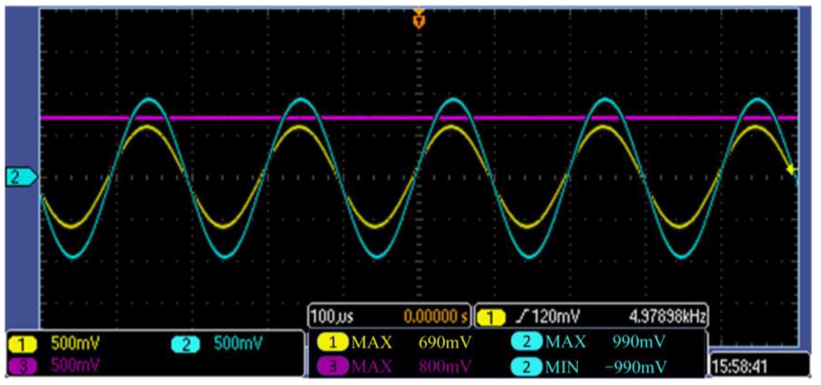
- To prevent irreversible hearing damage caused by high-decibel impulse noises (e.g., artillery blasts), we designed a protection attenuation circuit that effectively reduces excessive noise to a safe hearing range.
- 2.
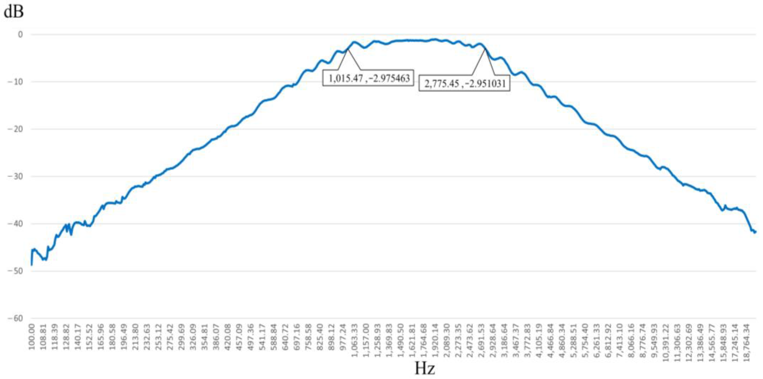
- An amplification circuit was developed to enhance low-volume vocal signals in military environments, ensuring clear command transmission while preventing additional hearing damage. A bandpass filter was also integrated to eliminate non-human noise, maintaining speech clarity.
- 3.
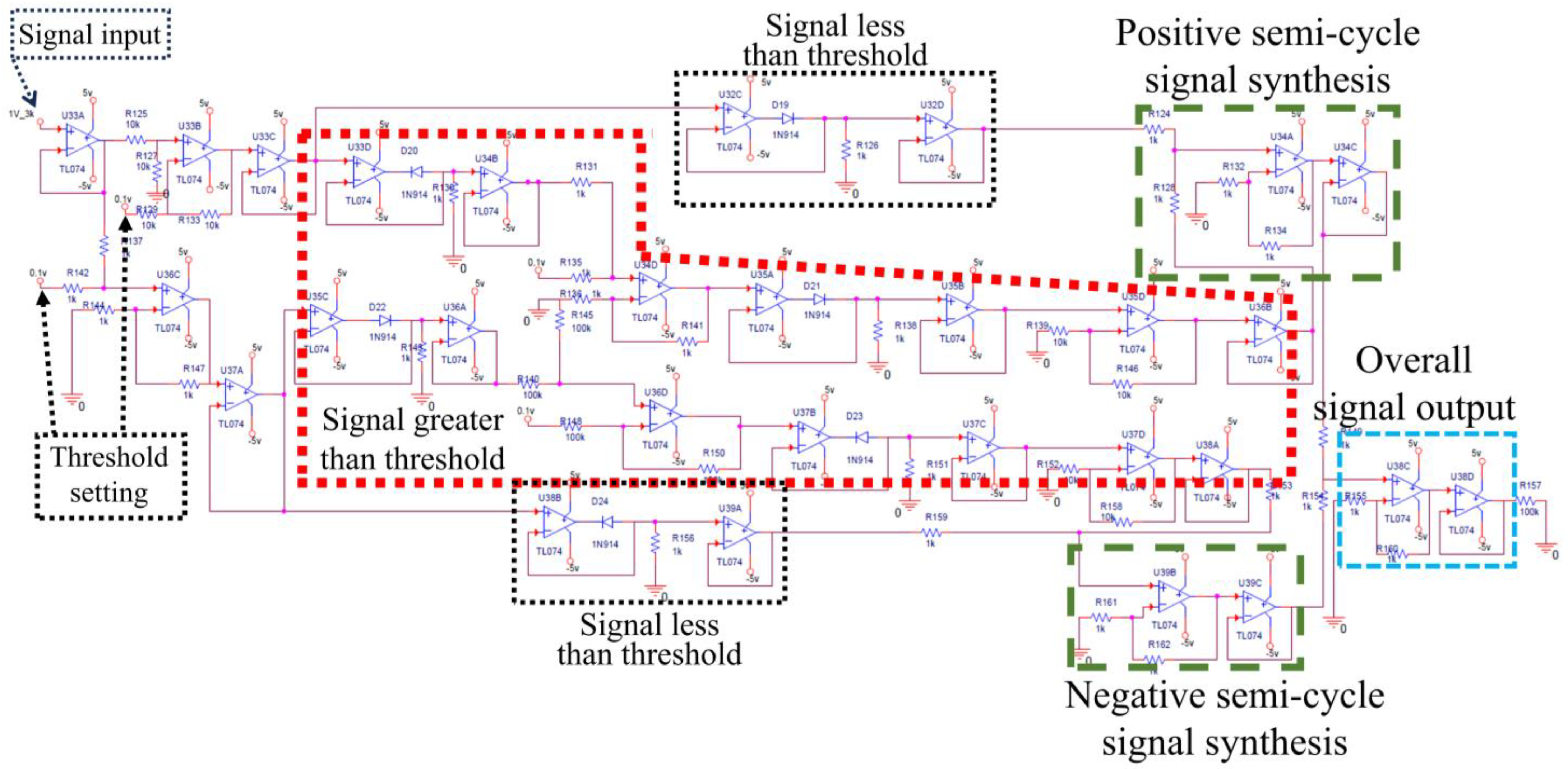
- To address signal distortion caused by switching circuit surge phenomena, we introduced a circuit-splitting approach that optimizes both attenuation and amplification circuits. This design enhances system stability and ensures reliable performance.
- 4.
- Unlike conventional studies that focus solely on short-term experimental outcomes, this research prioritizes long-term system stability and response repeatability. Extensive simulation and hardware testing ensured optimal component selection, fast audio processing, and high operational safety.
- 5.
- Each designed circuit and subsystem underwent multiple iterations of planning, simulation, and real-world testing to refine the selection of electronic components and ensure system robustness. The final active audio balance system delivers a low-distortion, fast-response output, making it reproducible and applicable for future developments in active noise control and audio signal processing.
2. System Design
2.1. Overview of the System
2.2. Active Noise Control
2.3. Controller and Adaptive Filtering
2.4. Feedback Noise Cancellation and Secondary Path Modeling
2.5. Outdoor Noise Management and Decision-Making System
2.6. Secondary Path Identification and Impact Noise Simulation
2.7. Bandpass Filtering and Voice Signal Amplification
3. Results and Discussion
3.1. Software Simulation and Parameter Selection
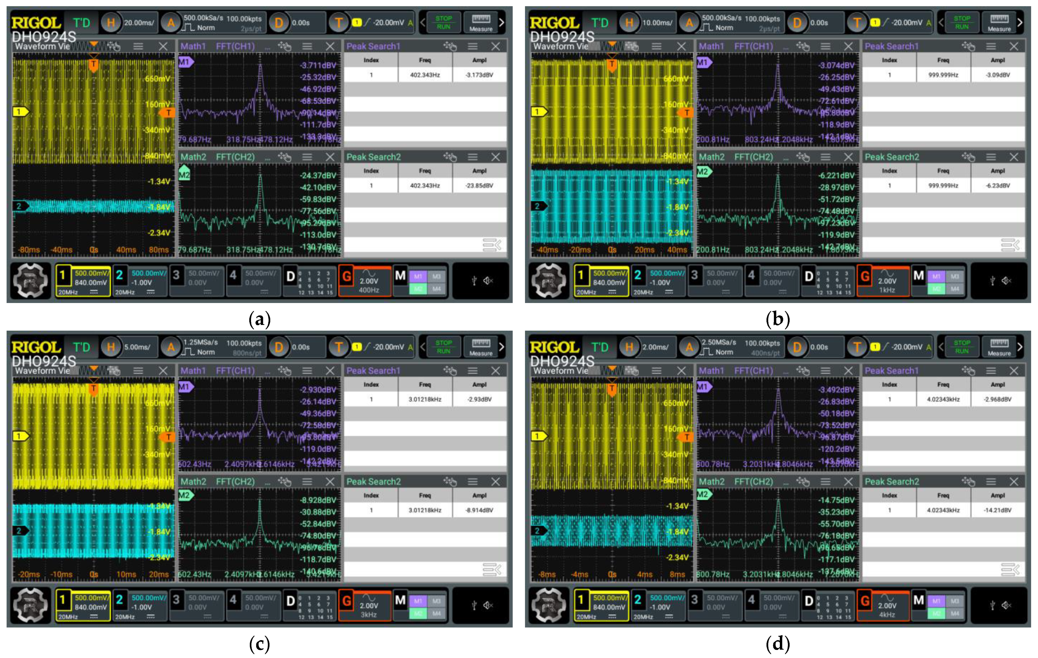
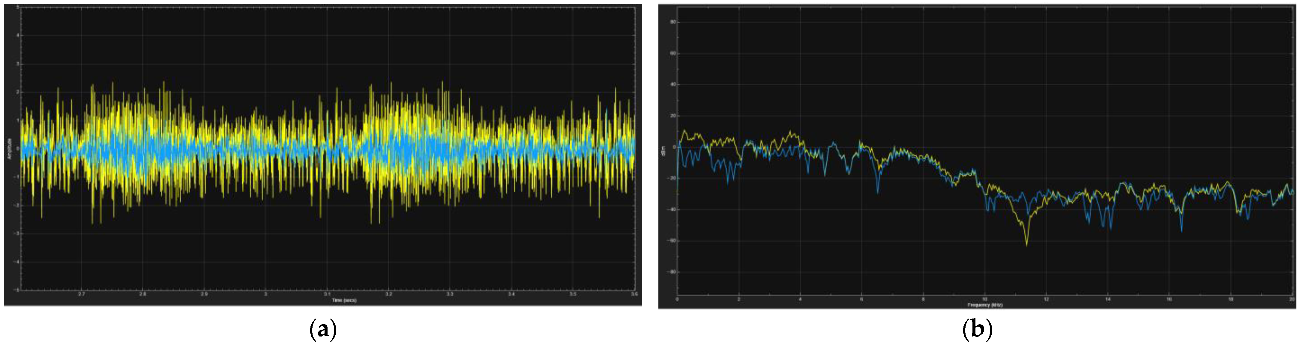
3.2. Hardware Implementation and Experimental Analysis
3.3. Comparison
4. Conclusions and Future Work
Author Contributions
Funding
Data Availability Statement
Conflicts of Interest
Abbreviations
| AANC | Adaptive active noise control |
| ABCC | Audio-balance control circuit |
| ANC | Active noise control |
| AINC | Active impulsive noise control |
| FxLMS | Filtered-x least mean squares |
| TGDFxLMS | Two-gradient direction FxLMS |
| HANC | Hybrid active noise control |
| PSO | Particle swarm optimization |
References
- Lu, L.; Yin, K.-L.; de Lamare, R.C.; Zheng, Z.; Yu, Y.; Yang, X.; Chen, B. A survey on active noise control in the past decade—Part I: Linear systems. Signal Process 2021, 183, 108039. [Google Scholar] [CrossRef]
- Shi, D.; Gan, W.-S.; Lam, B.; Shi, C. Two-gradient direction FXLMS: An adaptive active noise control algorithm with output constraint. Mech. Syst. Signal Process 2019, 116, 651–667. [Google Scholar]
- Shen, X.; Shi, D.; Gan, W.-S.; Peksi, S. Adaptive-gain algorithm on the fixed filters applied for active noise control headphone. Mech. Syst. Signal Process 2022, 169, 108641. [Google Scholar] [CrossRef]
- Meng, H.; Chen, S. Particle swarm optimization based novel adaptive step-size FxLMS algorithm with reference signal smoothing processor for feedforward active noise control systems. Appl. Acoust. 2021, 174, 107796. [Google Scholar] [CrossRef]
- Karthik, M.L.S.; Joel, S.; George, N.V. FxLMS/F Based Tap Decomposed Adaptive Filter for Decentralized Active Noise Control System. IEEE/ACM Trans. Audio Speech Lang. Process 2024, 32, 4691–4699. [Google Scholar]
- Chen, J.; Yang, J. A distributed FxLMS algorithm for narrowband active noise control and its convergence analysis. J. Sound Vib. 2022, 532, 116986. [Google Scholar]
- Tian, X.; Huang, J.; Feng, X.; Shen, Y. An intermittent FxLMS algorithm for active noise control systems with saturation nonlinearity. IEEE/ACM Trans. Audio Speech Lang. Process 2022, 30, 2347–2356. [Google Scholar]
- Liu, Y.; Lei, Z. Review of Advances in Active Impulsive Noise Control with Focus on Adaptive Algorithms. Appl. Sci. 2024, 14, 1218. [Google Scholar] [CrossRef]
- Wen, P.; Wu, Q.; Qu, B.; Yan, L.; Huang, F. Robust multi-reference adaptive gain FxLMS algorithm for active impulsive noise control. Appl. Acoust. 2024, 222, 110063. [Google Scholar]
- Ferrer, M.; García-Mollá, V.M.; Vidal-Maciá, A.M.; de Diego, M.; Gonzalez, A. Assessment of stability of distributed FxLMS active noise control systems. Signal Process 2023, 210, 109087. [Google Scholar]
- García-Mollá, V.M.; Ferrer, M.; de Diego, M.; Gonzalez, A. Selective collaboration in distributed FxLMS active noise control systems. Digit. Signal Process 2025, 156, 104829. [Google Scholar]
- Han, Y.; Chen, R. Active Noise Control System Based on Hybrid Fixed Filter Method and FxLMS Algorithm. In Proceedings of the 2023 7th International Conference on Electrical, Mechanical and Computer Engineering (ICEMCE), Xi’An, China, 20–22 October 2023; pp. 1–5. [Google Scholar]
- Xie, X.H.; Zhou, L.N.; Xie, Y.J. Design and Simulation of Active Noise Cancelling Earphone System Based on FXLMS Algorithm. In Proceedings of the 2022 4th International Conference on Natural Language Processing (ICNLP), Xi’An, China, 25–27 March 2022; pp. 626–630. [Google Scholar]
- Zhang, E.; Peng, Z.; Li, Z.; Lin, Y.; Zhuo, J. Four-Channel Active Noise Control Modeling and Offline Simulation for Electric Bus Sound Quality Based on Two FxLMS Algorithms. Acoust. Phys. 2024, 70, 143–152. [Google Scholar] [CrossRef]
- Bai, M.R.; Ih, J.-G.; Benesty, J. Acoustic Array Systems: Theory, Implementation, and Application; John Wiley & Sons: Hoboken, NJ, USA, 2013. [Google Scholar]
- Miljković, D. Active noise control: From analog to digital—Last 80 years. In Proceedings of the 2016 39th International Convention on Information and Communication Technology, Electronics and Microelectronics (MIPRO), Opatija, Croatia, 30 May–3 June 2016; pp. 1151–1156. [Google Scholar]
- Yang, F.; Guo, J.; Yang, J. Stochastic analysis of the filtered-x LMS algorithm for active noise control. IEEE/ACM Trans. Audio Speech Lang. Process 2020, 28, 2252–2266. [Google Scholar]
- Pandurangji, S. OPERATIONAL AMPLIFIER: Theory and Experiments; Springer: Berlin/Heidelberg, Germany, 2021. [Google Scholar]
- Kay, A. Operational Amplifier Noise: Techniques and Tips for Analyzing and Reducing Noise; Elsevier: Amsterdam, The Netherlands, 2012. [Google Scholar]
- Ali, M.E.H.R.; Attari, M.A. Design and implementation of ANC algorithm for engine noise reduction inside an automotive cabin using TMS320C5510. In Proceedings of the 2011 19th Iranian Conference on Electrical Engineering, Tehran, Iran, 17–19 May 2011; pp. 1–6. [Google Scholar]
- Chang, D.-C.; Chiang, P.-W. Trimmed-Mean FxLMS Algorithm for ANC in Impulsive Noise. In Proceedings of the 2018 Asia-Pacific Signal and Information Processing Association Annual Summit and Conference (APSIPA ASC), Honolulu, HI, USA, 12–15 November 2018; pp. 1268–1271. [Google Scholar]
- Jung, W.; Elliott, S.J.; Cheer, J. Local active control of road noise inside a vehicle. Mech. Syst. Signal Process 2019, 121, 144–157. [Google Scholar]
- Cheer, J.; Elliott, S.J. Active noise control of a diesel generator in a luxury yacht. Appl. Acoust. 2016, 105, 209–214. [Google Scholar]
- Ying, L.; Wang, J.; Liu, Q.; Wang, D. Application Study of Adaptive Tracking Algorithm in Active Noise Control System of Transformer. Appl. Sci. 2019, 9, 2693. [Google Scholar] [CrossRef]
- Jia, Z.; Zheng, X.; Zhou, Q.; Hao, Z.; Qiu, Y. A Hybrid Active Noise Control System for the Attenuation of Road Noise Inside a Vehicle Cabin. Sensors 2020, 20, 7190. [Google Scholar] [CrossRef] [PubMed]
- Dimino, I.; Colangeli, C.; Cuenca, J.; Vitiello, P.; Barbarino, M. Active Noise Control for Aircraft Cabin Seats. Appl. Sci. 2022, 12, 5610. [Google Scholar] [CrossRef]
- Liu, H.; Lee, J. A Feedback Active Control Approach to Road Noise Based on a Single Microphone Sensor to Improve Automotive Cabin Sound Comfort. Sensors 2024, 24, 2515. [Google Scholar] [CrossRef] [PubMed]


| System Order | Before Control (dB) | After Control (dB) | Variation Amount (dB) |
|---|---|---|---|
| 10 | 112.5 | 107.2 | 5.3 |
| 20 | 112.5 | 97.6 | 14.9 |
| 30 | 112.5 | 91.3 | 21.2 |
| 40 | 112.5 | 90.7 | 21.8 |
| 50 | 112.5 | 91.2 | 21.3 |
| 60 | 112.5 | 92.5 | 20 |
| 70 | 112.5 | 92.4 | 20.1 |
| 80 | 112.5 | 91.6 | 20.9 |
| 90 | 112.5 | 92.3 | 20.2 |
| 100 | 112.5 | 94.2 | 18.3 |
| System Order | Step Size | Pre-Control (dB) | Post-Control (dB) | Difference (dB) |
|---|---|---|---|---|
| 30 | 112 | 100.1 | 12.4 | |
| 30 | 112 | 98.0 | 14.5 | |
| 30 | 112 | 97.9 | 15.2 | |
| 30 | 112 | Unstable | Unstable | |
| 30 | 112 | Unstable | Unstable | |
| 40 | 112 | 99.1 | 13.4 | |
| 40 | 112 | 97.9 | 14.6 | |
| 40 | 112 | 96.8 | 15.7 | |
| 40 | 112 | Unstable | Unstable | |
| 40 | 112 | Unstable | Unstable | |
| 50 | 112 | 98.9 | 13.6 | |
| 50 | 112 | 97.5 | 13.3 | |
| 50 | 112 | 96.3 | 15 | |
| 50 | 112 | Unstable | Unstable | |
| 50 | 112 | Unstable | Unstable | |
| 60 | 112 | 99.2 | 13.3 | |
| 60 | 112 | 97.8 | 14.2 | |
| 60 | 112 | 96.5 | 14.4 | |
| 60 | 112 | Unstable | Unstable | |
| 60 | 112 | Unstable | Unstable | |
| 70 | 112 | 99.1 | 13.4 | |
| 70 | 112 | 98.0 | 14.1 | |
| 70 | 112 | 97.1 | 14 | |
| 70 | 112 | Unstable | Unstable | |
| 70 | 112 | Unstable | Unstable | |
| 80 | 112 | 99.3 | 12.9 | |
| 80 | 112 | 98.7 | 13.5 | |
| 80 | 112 | 97.7 | 14.8 | |
| 80 | 112 | Unstable | Unstable | |
| 80 | 112 | Unstable | Unstable | |
| 90 | 112 | 99.9 | 12.6 | |
| 90 | 112 | 99.3 | 13.2 | |
| 90 | 112 | 98.1 | 14.4 | |
| 90 | 112 | Unstable | Unstable | |
| 90 | 112 | Unstable | Unstable |
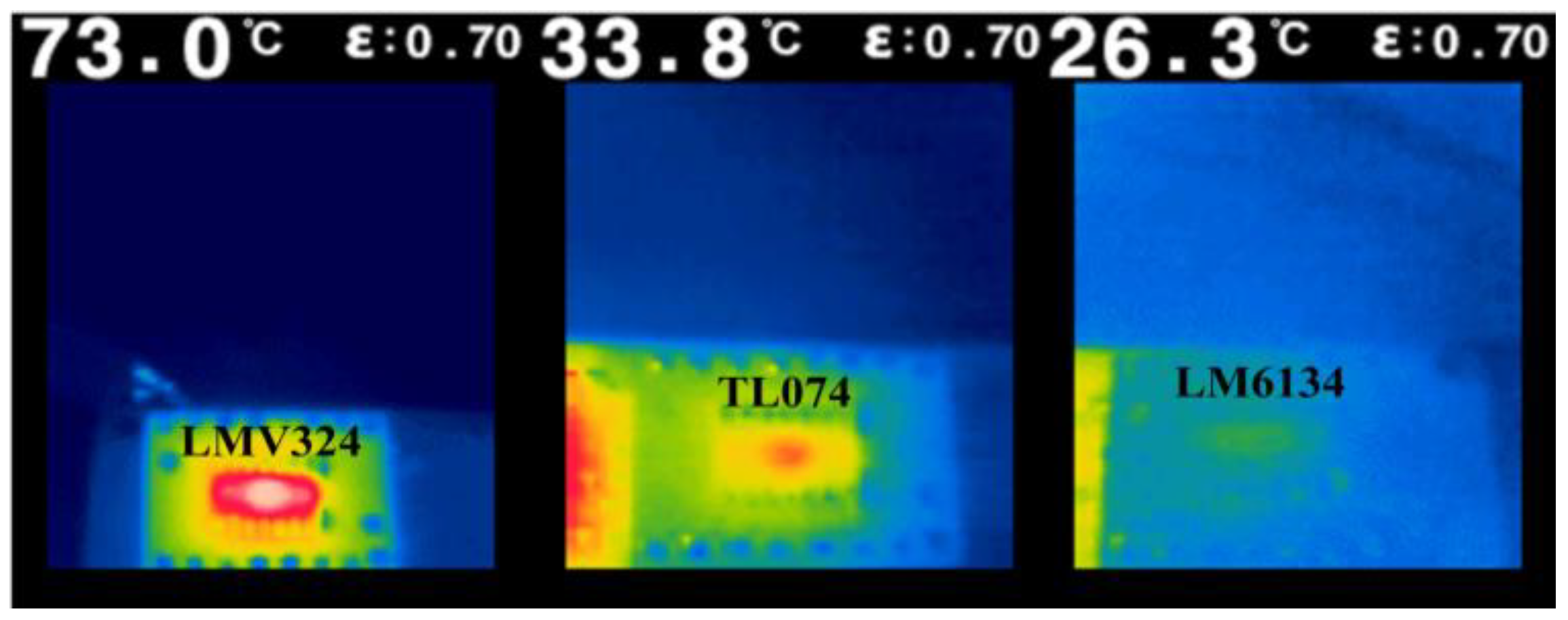
| OPA | Slew Rate | Rail to Rail | Switch Diode | Load | Maximum Distortion of the 1/4 Cycle | Maximum Distortion of the 3/4 Cycle | Error (mv) |
|---|---|---|---|---|---|---|---|
| TL074 | 13 (V/us) | In to V+ | 1n914 | 100 Ω | 351.957 mv | −0.6543 mv | 352.6113 |
| TL074 | 13 (V/us) | In to V+ | 1n914 | 1 KΩ | 368.915 mv | −6.3288 mv | 375.2438 |
| TL074 | 13 (V/us) | In to V+ | 1n914 | 10 KΩ | 382.506 mv | −56.507 mv | 439.013 |
| TL074 | 13 (V/us) | In to V+ | 1n4004 | 100 Ω | 312.723 mv | −193.436 mv | 506.159 |
| TL074 | 13 (V/us) | In to V+ | 1n4004 | 1 KΩ | 346.607 mv | −192.159 mv | 538.766 |
| TL074 | 13 (V/us) | In to V+ | 1n4004 | 10 KΩ | 503.545 mv | −326.736 mv | 830.281 |
| Opa197 | 20 (V/us) | In, Out | 1n914 | 100 Ω | 148.652 mv | −1.3202 mv | 149.9722 |
| Opa197 | 20 (V/us) | In, Out | 1n914 | 1 KΩ | 229.230 mv | −12.371 mv | 241.601 |
| Opa197 | 20 (V/us) | In, Out | 1n914 | 10 KΩ | 281.818 mv | −95.559 mv | 377.377 |
| Opa197 | 20 (V/us) | In, Out | 1n4004 | 100 Ω | 150.952 mv | −203.511 mv | 354.463 |
| Opa197 | 20 (V/us) | In, Out | 1n4004 | 1 KΩ | 250.073 mv | −205.315 mv | 455.388 |
| Opa197 | 20 (V/us) | In, Out | 1n4004 | 10 KΩ | 123.796 mv | −420.276 mv | 544.072 |
| TLV9352 | 20 (V/us) | In to V−, Out | 1n914 | 100 Ω | 250.073 mv | −0.92112 mv | 250.99412 |
| TLV9352 | 20 (V/us) | In to V−, Out | 1n914 | 1 KΩ | 507.355 mv | −8.6397 mv | 515.9947 |
| TLV9352 | 20 (V/us) | In to V−, Out | 1n914 | 10 KΩ | 579.425 mv | −76.823 mv | 656.248 |
| TLV9352 | 20 (V/us) | In to V−, Out | 1n4004 | 100 Ω | 243.671 mv | −200.491 mv | 444.162 |
| TLV9352 | 20 (V/us) | In to V−, Out | 1n4004 | 1 KΩ | 467.421 mv | −196.289 mv | 663.71 |
| TLV9352 | 20 (V/us) | In to V−, Out | 1n4004 | 10 KΩ | 320.669 mv | −372.314 mv | 692.983 |
| Opa810 | 200 (V/us) | In to V−, Out | 1n914 | 100 Ω | 67.672 mv | −3.1010 mv | 70.773 |
| Opa810 | 200 (V/us) | In to V−, Out | 1n914 | 1 KΩ | 80.285 mv | −26.249 mv | 106.534 |
| Opa810 | 200 (V/us) | In to V−, Out | 1n914 | 10 KΩ | 165.539 mv | −126.372 mv | 291.911 |
| Opa810 | 200 (V/us) | In, Out | 1n4004 | 100 Ω | 73.264 mv | −213.165 mv | 286.429 |
| Opa810 | 200 (V/us) | In, Out | 1n4004 | 1 KΩ | 149.746 mv | −217.955 mv | 367.701 |
| Opa810 | 200 (V/us) | In, Out | 1n4004 | 10 KΩ | 409.660 mv | −458.050 mv | 867.71 |
| Opa820 | 240 (V/us) | No | 1n914 | 100 Ω | 221.196 mv | −6.8679 mv | 228.0639 |
| Opa820 | 240 (V/us) | No | 1n914 | 1 KΩ | 214.617 mv | −51.528 mv | 266.145 |
| Opa820 | 240 (V/us) | No | 1n914 | 10 KΩ | 145.079 mv | −275.602 mv | 420.681 |
| Opa820 | 240 (V/us) | No | 1n4004 | 100 Ω | 228.326 mv | −218.057 mv | 446.383 |
| Opa820 | 240 (V/us) | No | 1n4004 | 1 KΩ | 204.947 mv | −258.748 mv | 463.695 |
| Opa820 | 240 (V/us) | No | 1n4004 | 10 KΩ | 105.586 mv | −572.584 mv | 678.17 |
| Proposed Methods | Paper [22] | Paper [23] | Paper [24] | Paper [25] | Paper [26] | Paper [27] | ||
|---|---|---|---|---|---|---|---|---|
| AANC | ABCC | |||||||
| Consider the second path impact | Yes | No | No | No | No | Yes | No | Yes |
| Maximum analysis frequency band | 2 kHz | 8 kHz | 1 kHz | 250 Hz | 100 Hz, 200 Hz, 300 Hz, 400 Hz, 500 Hz | 70–85 Hz, 100–500 Hz | 200 Hz | 300 Hz |
| Average noise reduction | 10 dB | Attenuation ratio 1/10 | 3.7 dB | None | 5 dB | 3.7 dB | 20 dB | 10 dB |
| Maximum noise reduction | 21.8 dB | Attenuation ratio 1/10 | In 747 Hz, noise reduction 8.6 dB | In 50 Hz, noise reduction 23 dB | 5 dB | 3.7 dB | 20 dB | 30 dB |
Disclaimer/Publisher’s Note: The statements, opinions and data contained in all publications are solely those of the individual author(s) and contributor(s) and not of MDPI and/or the editor(s). MDPI and/or the editor(s) disclaim responsibility for any injury to people or property resulting from any ideas, methods, instructions or products referred to in the content. |
© 2025 by the authors. Licensee MDPI, Basel, Switzerland. This article is an open access article distributed under the terms and conditions of the Creative Commons Attribution (CC BY) license (https://creativecommons.org/licenses/by/4.0/).
Share and Cite
Chen, T.-Y.; Yang, J.-H.; Lai, C.-L.; Wei, C.-T. Low-Frequency Active Noise Control System Based on Feedback FXLMS. Electronics 2025, 14, 1442. https://doi.org/10.3390/electronics14071442
Chen T-Y, Yang J-H, Lai C-L, Wei C-T. Low-Frequency Active Noise Control System Based on Feedback FXLMS. Electronics. 2025; 14(7):1442. https://doi.org/10.3390/electronics14071442
Chicago/Turabian StyleChen, Ting-Yu, Jia-Horng Yang, Chien-Liang Lai, and Chun-Ta Wei. 2025. "Low-Frequency Active Noise Control System Based on Feedback FXLMS" Electronics 14, no. 7: 1442. https://doi.org/10.3390/electronics14071442
APA StyleChen, T.-Y., Yang, J.-H., Lai, C.-L., & Wei, C.-T. (2025). Low-Frequency Active Noise Control System Based on Feedback FXLMS. Electronics, 14(7), 1442. https://doi.org/10.3390/electronics14071442