Abstract
Recently, the concept of cell-free massive multiple-input multiple-output (CF-mMIMO) has been implemented in low-Earth-orbit (LEO) constellations to enhance energy efficiency. However, signal distortion caused by nonlinear power amplifiers (NPAs) significantly degrades the performance of LEO satellite communication (SATCOM) links. In this paper, we propose a serving cluster scheme and a hybrid precoding framework for CF-mMIMO-assisted LEO SATCOM systems, aiming to suppress the impact of NPAs while reducing onboard hardware complexity and power consumption. Specifically, we first develop a user-centric access point clustering strategy that incorporates elevation constraints and channel fading. Then, we formulate a precoding optimization problem to maximize energy efficiency by treating the product of tightly coupled analog and digital matrices as a single fully digital precoder. The proposed distortion-aware precoding design is achieved by integrating the weighted minimum mean square error (WMMSE) approach with a gradient descent method enhanced by Nesterov’s accelerated momentum. Furthermore, an efficient hybrid precoding method based on alternating minimization is proposed to address the matrix decomposition challenge. Simulation results validate the effectiveness of our proposed user-centric serving clustering algorithm and the WMMSE-based precoding algorithm in CF-mMIMO-assisted LEO SATCOM systems.
1. Introduction
Non-terrestrial networks (NTNs), which are aimed at achieving seamless global coverage and supporting high data rate services, will be an important part of the Beyond-5G (B5G) and 6G ecosystems. Within the NTN, low-Earth-orbit (LEO) giant constellations have attracted significant interest in recent years [1]. Compared to geostationary Earth orbit (GEO) satellites, LEO satellites can effectively reduce the long propagation delays and high path losses and then provide a more favorable communication and networking environment [2]. In satellite-to-ground communication systems, the received power is often weak when the ground users (GUs) receive signals directly from the satellites. To increase the received power, one can choose to increase the transmit power or gain of a single satellite or to use multiple satellites cooperatively. Multi-satellite cooperation should be a better solution to cope with the problem of cost and flexibility [3]. However, due to the mobility of LEO, spectrum management has become an urgent challenge, and cell-free (CF) communication systems have also been identified as a potential source of improved SE in ongoing works [4].
Despite the challenges posed by the escalated costs of hardware equipment and the intricate system complexity of CF systems, contemporary mobile communications continue to exhibit a growing predilection towards this architecture. CF massive multiple-input multiple-output (CF-mMIMO) is a distributed massive multiple-input multiple-output (mMIMO) technique. The model was first proposed in [5]. CF-mMIMO networks deploy a large number of access points (APs) to serve GUs, which can provide ubiquitous connectivity with high spectral efficiency (SE) and energy efficiency (EE). Thus, it can be one of the promising technologies for B5G and 6G wireless networks [6,7,8].
Due to the high density of LEO constellations, it is highly feasible to use CF-mMIMO architectures to improve the performance of satellite networks [2]. The author of [9] proposed an integrated space-terrestrial architecture that combines ultra-dense terrestrial deployment with the extensive coverage of LEO satellites, aiming at maximizing the minimum per-user rate in the coverage area. Subsequently, they proposed an integrated network architecture combining a CF-mMIMO terrestrial network layout with LEO satellites to manage terrestrial-to-satellite user transfers using scalable techniques In [10]. The great potential of LEO satellites in supporting and expanding CF-mMIMO terrestrial coverage is revealed.A user demand-based quantum activation strategy was proposed in [11] for LEO satellites in CF-mMIMO communications. The authors in [12] proposed a scalable distributed mMIMO system for LEO satellite networks based on user-centric dynamic clustering, which can improve the system’s SE and minimize the serving cluster (SC) size for each GU.
However, since satellites use multi-beam transmission techniques, full-frequency multiplexing is often employed, resulting in inter-beam interference. Therefore, linear precoding is used at the transmitter to mitigate the interference [13]. Due to the limited complexity and favorable performance, precoding architectures based on hybrid analog/digital precoding were widely applied in satellite communication systems [14]. The hybrid precoding scheme is capable of reducing the hardware cost and power consumption of the system. When integrated with suitable precoding algorithms, this approach can significantly enhance the overall system performance. A hybrid analog/digital precoding technique was developed in [13] in an mMIMO LEO satellite communication (SATCOM) downlink using a dual-resolution phase-shift network. The authors in [14] proposed a hybrid precoding architecture based on dynamic subarrays and low-resolution phase shifters. A hybrid transmitting precoding scheme under spectrum-sharing constraints in a backhaul system was proposed in [15]. Compared to the fully digital precoding scheme, the cost and complexity are greatly reduced with a slight performance degradation. Ref. [16] proposed a robust energy-efficient hybrid precoding scheme under the constraints of transmit power and quality of service (QoS). In [17], the authors introduced a multi-LEO-satellite communication network, which combines a hybrid precoding architecture and heuristic user scheduling algorithms. The superior performance of the proposed scheme was confirmed. In [18], the performance of hybrid precoding for mMIMO LEO satellites is analyzed by utilizing a fully connected hybrid antenna array structure. The performance is also compared with fully digital precoding and analog precoding. Furthermore, a hybrid precoding design scheme considered resource allocation for multi-user mMIMO LEO satellite communication systems was proposed in [19].
In mMIMO downlink LEO satellite communication systems, nonlinearities of power amplifiers (PAs) cause nonlinear distortions in the transmitted signals, leading to performance degradation. In previous works, the authors in [20] investigated the distortion generated by mMIMO base stations with nonlinear power amplifiers (NPAs) and obtained the spatial inter-correlation matrix of nonlinear distortion. It helps to predict the behavior of nonlinear distortion. Ref. [21] modeled the nonlinear amplified signal of a multi-antenna transmitter and analyzed the performance of a multiple-input multiple-output (MIMO) millimeter-wave hybrid precoding scheme in the presence of nonlinear beams. This model is employed in [13,22,23]. Ref. [22] builds on [21] and investigates the design of distortion-aware precoding utilizing the classical weighted minimum mean square error (WMMSE) framework and proposes an algorithm to solve the equivalent WMMSE optimization problem in precoding design. In [23], a distortion-aware precoding design was proposed for SATCOM downlink system with NPAs at the satellite transmitters. Based on the aforementioned research, this paper focuses on the hybrid precoding design of the downlink in an integrated network architecture combining CF-mMIMO and LEO satellites with the nonlinear distortion of NPAs. The main contributions of this paper are as follows:
- We establish a comprehensive downlink transmission model for CF-mMIMO-assisted LEO SATCOM systems under the impact of NPAs. To quantify the distortion effects, the NPAs are modeled as finite-order memoryless polynomials, explicitly characterizing their in-band distortion. The formulation provides a tractable framework for analyzing and mitigating NPA-induced signal impairments.
- A user-centric SC strategy is proposed to optimize satellite–ground collaboration in CF-mMIMO LEO systems, where multiple satellites cooperatively serve multiple GUs. The strategy adaptively selects serving satellites for each GU by jointly considering the elevation angle and channel fading. Based on the proposed strategy, the link relationships between APs and GUs can be represented through a set of binary diagonal matrices, enabling low-complexity cluster management and resource allocation.
- A hybrid precoding problem for EE maximization is formulated by taking the product of tightly coupled analog and digital matrices as a single fully digital precoder. As for the fully digital precoding problem, we transform it into a linear programming problem by adopting an auxiliary variable and then use the WMMSE framework and a gradient descent method with Nesterov’s accelerated momentum to solve it. Additionally, we design the hybrid analog/digital precoders based on the principle of alternating minimization.
The rest of this paper is organized as follows: Section 2 discusses the system model with NPAs and formulates the EE maximization problem. An algorithmic approach is developed to form the SCs in Section 3. Section 4 investigates the precoding design for the EE maximization and discusses the design of hybrid analog/digital precoders with partially connected architectures. Section 5 presents the numerical results, and the conclusion of this paper is given in Section 6.
Notation: The following notations are adopted throughout this paper. Boldface upper case letters refer to matrices, and boldface lower case letters denote column vectors. The transpose, conjugate transpose and inverse are represented by , , and , respectively. and stand for the -norm of vectors and the Frobenius norm of matrices, respectively. The expectation of a variable is noted by . ⊙ and ⊗ denote the Hadamard products and the Kronecker products of two matrices, respectively. We use , which represents an N-dimensional diagonal matrix with on the diagonal, and represents a diagonal matrix where the diagonal entries are the same as the matrix . The normal distribution is denoted by , where is the variance of the normal distribution. The ceil value of x is represented as .
2. System Model
2.1. Channel Model
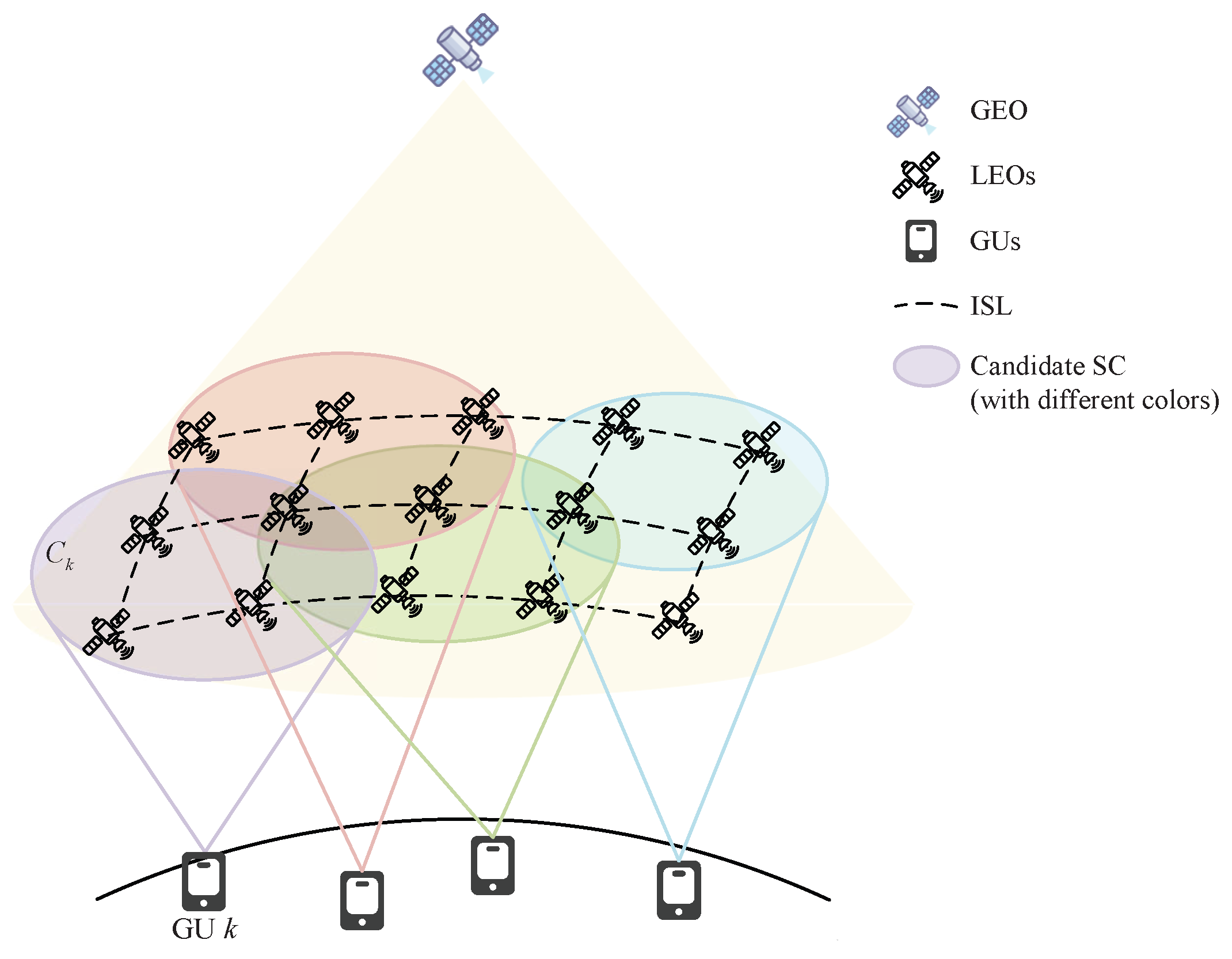
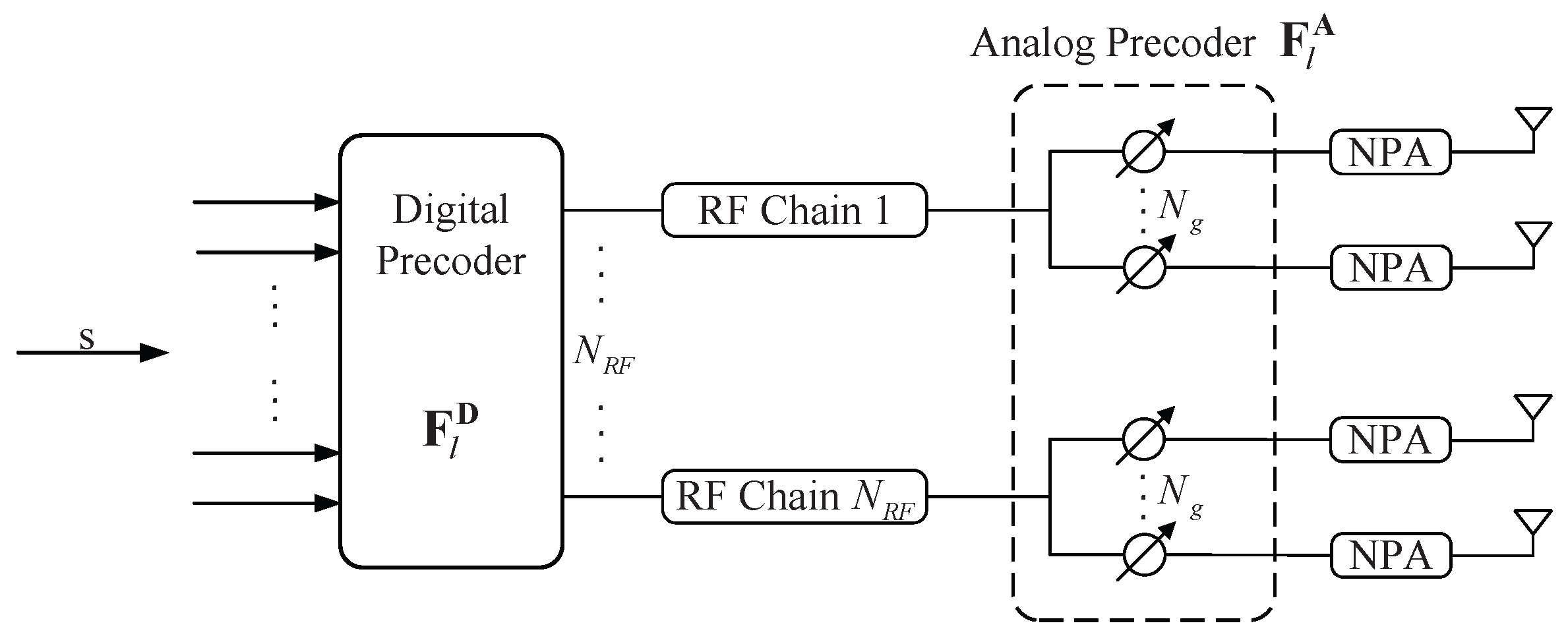
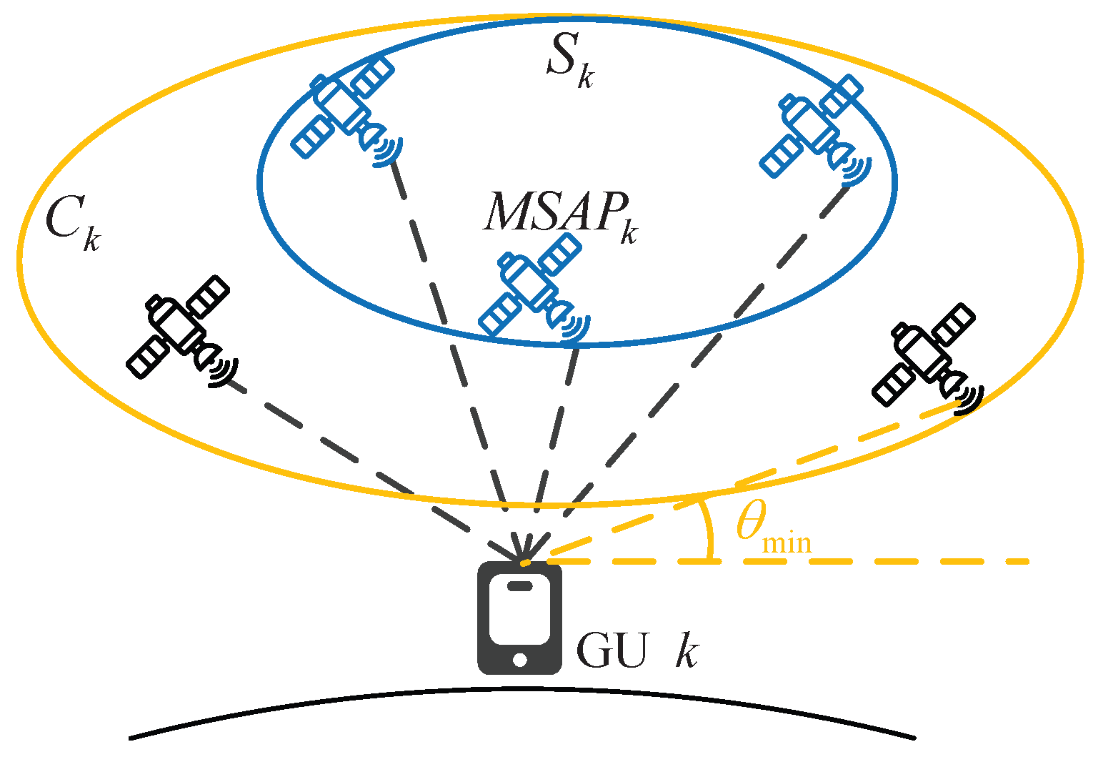
As depicted in Figure 1, we consider a downlink communication scenario where multiple LEO satellites cooperatively provide services for GUs with a GEO satellite working as a central processing unit (CPU). Inter-satellite links (ISLs) are employed to exchange data among satellites. In the proposed CF-mMIMO-assisted LEO SATCOM system, L LEO satellites cooperatively serve K single-antenna GUs, and each GU is served by multiple satellites simultaneously. It is assumed that each satellite contains a uniform planar array (UPA) of N antenna units, with and antenna units on the x-axis and y-axis, respectively. Antenna spacings are half of the wavelength, and each antenna is equipped with a PA. The UPA adopts a hybrid analog/digital precoding architecture, where the number of RF chains is , and the number of array elements contained in each RF chain is . The diagram of the hybrid precoding architecture is shown in Figure 2.
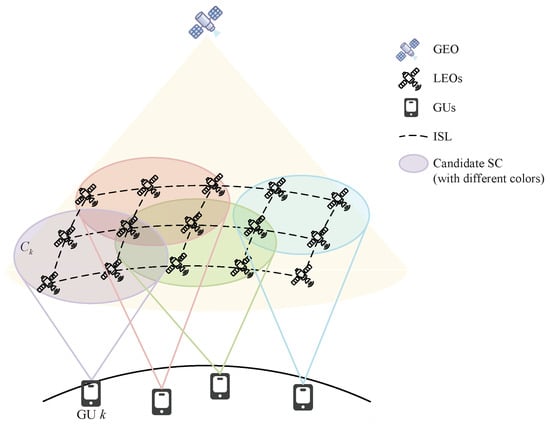
Figure 1.
System architecture of the multi-satellite cooperative communication network in a CF-mMIMO-assisted LEO SATCOM system with a set of LEO satellites working as APs that jointly serve GUs. The SC for GU k is further obtained from candidate SC by Algorithm 1.
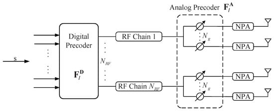
Figure 2.
The partially connected hybrid precoding architecture with NPAs at the transmitter.
The channel between the kth GU and the lth satellite is denoted by , which is modeled as
where and denote the complex channel gain and the UPA response vector of the path between the kth GU and the lth satellite, respectively.
| Algorithm 1: Initial GU access and SC selection. |
|
The variable is affected by large-scale fading and antenna gain, which is expressed as
where is the satellite-side antenna gain, is the GU-side antenna gain and is the large-scale fading between the kth GU and the lth satellite.
The large-scale fading (in dB) between the kth GU and the lth satellite is calculated by [24]
where denotes the basic path loss, represents the losses due to the shadowing effect, denotes the gain losses due to beam misalignment, and denotes other large-scale losses, such as atmospheric gasses attenuation and ionospheric scintillation.
The basic path loss is a function of the operating frequency and the distance between the kth GU and the lth satellite, which can be expressed as
The shadow fading loss is modeled as a log-normal random variable, i.e., , where denotes shadowing variance.
is modeled as [24]
where is the first-kind and first-order Bessel function, denotes the bore-sight angle of the lth satellite’s antenna beam with respect to the kth GU, and denotes the aperture radius of the antenna in wavelengths.
Since the heights of scatterers near the GUs are usually much lower than those of the satellites, it can be assumed that the propagation paths of all the antennas have the same angle for both the kth GU and the lth satellite, and each antenna of the satellites can be denoted by , where and are the spatial angles obtained by the transformation of the angle of divergence (AoD) and , , . For , channel direction vectors can be expressed as for the kth GU and the lth satellite [25].
2.2. Nonlinear PA Model
The vector denotes the transmission signal, where and are satisfied. On the lth satellite, the signal is firstly digitally precoded at baseband by a digital precoding matrix . Then, the signal is precoded by an analog precoder , where contains non-zero elements corresponding to phase shifters in the network connected to the ith RF chain of size . denotes the hybrid precoding matrix on the lth LEO satellite, where denotes the precoding of the lth satellite to the kth GU. denotes the digital precoding matrix on L LEO satellites, denotes the analog precoding matrix on L LEO satellites. According to the above hybrid architecture, the expression for the hybrid precoder of the whole system is , and .
On the lth satellite, the signal after hybrid precoding is denoted by , . We can obtain and . After being precoded, the signal vector is amplified by the NPAs. Assuming that each NPA has the same input-output relation , the output signal of the nth NPA on the lth satellite is [21]
where denotes Complex th-order model coefficient. The instantaneous gain of the nth NPA is expressed as
Each NPA employs a memoryless nonlinear model, which is typically valid within a moderate bandwidth range. As demonstrated in [26], only the odd orders of the polynomial contribute to the in-band distortion. Since the focus is only on the in-band distortion, which can be characterized by odd orders, the nonlinear effects of NPAs are generally smooth. Thus, we can limit our attention to the limited-order polynomial NPA model by setting M = 1 in Equation (7) [27], which is modeled as [23]
On the lth satellite, the output signal of the NPAs can be expressed as [21]
where denotes the instantaneous gain of the NPAs, and denotes the average linear amplification gain. The distortion of the NPAs on the lth satellite is given by , which is assumed to be independent of the signal vector .
According to Equation (9), we can obtain that the nth element of the emitted signal on the lth satellite can be written as , where
and where denotes the average input power of the nth PA on the lth satellite. Thus, the average linear amplification gain matrix of the PAs on the lth satellite can be obtained as .
From the above derivation, it follows that . Hence, we can obtain [21]
Introducing the above derivation into a system with L satellites, we can obtain that and . Similarly, .
2.3. Downlink Transmission
In the downlink, the received signal of the kth GU is
where is the additive Gaussian white noise for the kth GU.
To facilitate the analysis of the cooperative cluster architecture, we define a matrix to represent the transmission relationship between the lth satellite and GUs, and a value of 1 for the jth diagonal element of indicates that the lth satellite transmits a signal to the ith GU through the jth antenna, where can be defined as
and where denotes the lth element of the service relationship matrix between the ith GU and the satellites.
2.4. Problem Formulation
In the downlink transmission, the SINR of the kth GU can be expressed as
The data rate of the kth GU can be expressed as
Therefore, the corresponding sum rate is given by .
The EE is defined as the ratio of the weighted sum rate to the total power consumption. The total power consumption is expressed as in our proposed system, where denotes the power consumed by the NPAs with the maximum operating efficiency . In addition, denotes the power consumption of the circuit including elements such as the local oscillator, baseband digital precoder, RF chain, etc., and denotes the basic power consumption such as power supply and cooling of the satellite.
Circuit power consumption is expressed as , where denotes the power consumption of each RF chain, including a digital-to-analog converter (DAC), mixer, and filter. , , and denotes the power consumption of the local oscillator, baseband digital precoder, each phase shifter switch, and each phase shifter, respectively.
In this paper, we seek to maximize the EE within the constraints of the average total transmit power per satellite. The optimization problem of the EE maximization can be expressed as [28]
where is the bandwidth, is the total system power consumption and P denotes the limit on the average total transmit power per satellite. Additionally, we have
3. Cluster Formulation
In this section, we discuss the downlink transmission of the proposed architecture and design a SC formation method.
In the downlink network considered in this paper, each GU is connected to a set of nearby satellites. The backhaul link connects the LEO satellites to the GEO satellites, which serve as a CPU to pass the necessary control signals between them. A specified minimum elevation angle determines the GU’s candidate service satellite. To ensure a flexible and scalable configuration, each GU is assigned a Master Satellite AP (MSAP) based on the given criteria. In the following, we propose an algorithm for SC formation:
- Step 1:
- According to the given minimum elevation angle , the candidate SCs are selected for each GU. The lth satellite is added to the kth GU’s set of candidate satellites when the elevation angle of the lth satellite relative to the kth GU satisfies .
- Step 2:
- For the kth GU, sequentially traverse the satellites in the set , and select the satellite corresponding to the maximum value of as the candidate MSAP. Determine whether the satellite is idle or not. If it is idle, then it is selected as the MSAP for the kth GU and denoted as . If it is not idle, traverse in order of value until is selected among the idle satellites. The K MSAPs of the K GUs are selected sequentially by this step, and the MSAPs are removed from the sets of candidate satellites and added to the sets of serving clusters.
- Step 3:
- Choose other accessible satellites to serve the GUs together with MSAPs. In order to ensure rational allocation of resources, the GUs are traversed to select the service satellites sequentially. Each round of traversal sequentially adds a service satellite to the candidate set of K GUs to the service cluster of the GU. The criteria for adding is that the large-scale fading coefficient between the satellite and the GU is maximum and the satellite is idle. The selected satellite is removed from sets of candidate satellites after successful addition until all the satellites in the candidate cluster are selected for all GUs.
The SC formation strategy is summarized as Algorithm 1.
As shown in Figure 3, the candidate set for the kth GU is dependent on the elevation angle. Considering the large-scale fading between the kth GU and the satellites, an optimal satellite is first selected as the for the kth GU among the available satellites, and then the others are selected sequentially.
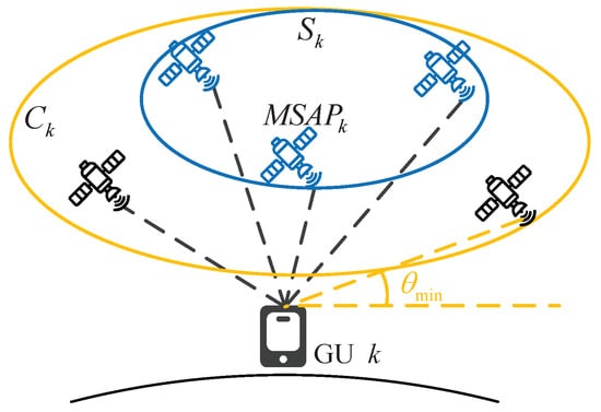
Figure 3.
SC formation for the kth GU.
For simulation efficiency, our design incorporates a relatively small number of satellites and GUs. When a satellite is tasked with serving a GU, we configure all antennas on that satellite to transmit data exclusively for that GU. In contrast, systems employing a hybrid precoding scheme based on a partially connected architecture typically employ a subarray of antennas connected to the same RF chain to serve a single GU. The number of GUs served by a satellite simultaneously should not exceed the number of RF chains on the satellite. It is worth noting that our proposed service clustering algorithm can be readily extended to accommodate this configuration by merely adjusting the criteria for determining the idle status of a satellite. For instance, when assessing whether the lth satellite is idle for the kth GU, it is necessary to examine the state of each RF chain on the satellite. Specifically, the matrix is treated as a diagonal matrix that comprises block matrices. By traversing the diagonal elements of each block matrix, we can determine the availability of the RF chains. If there exists a block matrix whose diagonal elements are all zero for , this indicates that the RF chain on the lth satellite is idle and capable of serving the kth GU.
4. Energy Efficiency
In this section, we discuss the precoding for a downlink CF-mMIMO-assisted LEO SATCOM system based on the EE maximization criterion. Due to the effect of NPAs, the signal received by a single GU contains interference from other GUs and signal distortion except for the desired signal. In this paper, we treat the signal distortion as noise and utilize the model of NPAs introduced in Section 2. In addition to this, we have to consider the connection between the satellites and the GUs. Moreover, the investigation of EE maximization is more complex than the investigation of SE maximization.
4.1. Optimization of Energy Efficiency
The average total power consumption of a single satellite can be written as
Hence, the objective function in Equation (16) can be further written as
To further process the objective function (19), a nonlinear variable transformation is used to transform the objective function into a linear programming problem by introducing an auxiliary variable . Function (19) can be reformulated into the following univariate equation:
The range of values of can be obtained from [29] as
If makes the optimal value of Function (20), then the solution of the above optimization function (Function (20)) is the optimal solution of Function (19). The optimal value of can be found based on the algorithm for finding the optimal univariate parameter in [29].
Assuming below that the value of is given, the objective function (Function (20)) can be further rewritten as
The objective function and constraints in (16) are non-convex and the relevant optimization variables are coupled. In the following, we approach this problem by using a WMMSE-based algorithm to exploit the relationship between the achievable rate and the MSE of the optimal receiver [22].
Based on the analysis above, the problem (16) can be equated to the following WMMSE problem [30]:
where denotes the weight coefficient of the kth GU and denotes the mean square error (MSE) of the kth GU, which can be written as
where denotes the estimated signal for the kth GU, and is the receiver gain.
We use a block coordinate descent (BCD) method to solve this problem. The WMMSE objective function is minimized by fixing two of the three variables sequentially and updating the third. The closed update form for r and w can be derived as
Fixing and , the problem in Equation (23) can be transformed into
where .
This problem equation (Equation (27)) is non-convex for the precoding matrix due to the complex nonlinear distortion terms involved in the rate utility and power constraints. We utilize an enhanced projected gradient descent method to solve this problem efficiently [22]. The gradient of the objective function is evaluated using a gradient descent method with Nesterov’s accelerated momentum at the estimated position, which can be expressed as [22]
where reflects the coupling of the gradient update at the current iteration with the previous iteration, and is involved in predicting the previous position step. The parameter corresponds to the learning rate in the gradient update. , where denotes the weighted mean square of the gradient and is expressed as
The gradient of the objective function is calculated by [22,23]
where , , and is an extremely small normal number. is an matrix with at the th row and kth column and zero entries at all other positions. Analogously, is an matrix with only non-zero entry being at the th row and kth column.
After calculating , needs to be projected to the feasible region to ensure that the power constraints through the bisection method.
This WMMSE-based precoding algorithm is summarized in Algorithm 2.
| Algorithm 2: WMMSE-based precoding algorithm for EE maximization. |
|
4.2. Hybrid Precoding for the Partially Connected Architectures
The study of hybrid precoding in MIMO-based systems has been mentioned in many works [13,14,15,16,17,18,19,31,32]. In this section, the digital precoder and the analog precoder are designed by minimizing the Euclidean distance between and the equivalent fully digital precoder , which is given by
We will solve the design of this hybrid precoding architecture by dividing it into two subproblems: analog precoder design and digital precoder design [33].
4.2.1. Analog Precoder Design
Based on the structural properties of the analog precoder for the partially connected architectures, we can initialize the analog precoding matrix by using the phased-zero-forcing (PZF) precoding proposed in [34]. The analog precoding matrix uses a phase-shifting network to map the signals from the RF chain to the transmit antenna. Therefore, each phase shifter in the network should satisfy the unit-mode constraint, which is translated into a constraint on each entry of the analog precoding matrix. For the lth satellite, . Initialize element , where denotes the phase of the element in . In practical implementations, the phase of each entry is often quantized due to the practical constraints of variable phase shifters. Therefore, the performance of the PZF precoding scheme needs to be investigated in this realistic scenario, i.e., the phase of the entries of is quantized to B-bit precision. Each phase is quantized to its nearest neighbor according to the closest Euclidean distance. Thus, the phase of each term of is written as , where
Therefore, the analog precoder design can be expressed as
where denotes a set of block matrices after being quantized, with an dimension non-zero vector in each block.
As shown in [33], there exists a closed-form expression for , which can be written as
4.2.2. Digital Precoder Design
The subproblem of the digital precoder design can be expressed as
After we converge for the analog precoding, the solution of the digital precoding matrix can be obtained from the power constraint in Equation (36). The design of the digital precoder is more complicated due to the effect of the nonlinearity of the PAs, and the design process is explained in detail in Appendix A.
5. Simulation Results and Analysis
In this section, we evaluate the EE of the precoding technique based on the WMMSE algorithm in the CF-mMIMO LEO SATCOM downlink, taking into account the signal distortion introduced by the NPAs.
5.1. Setup and Parameters
The proposed system in this paper operates in the Ku band. The values of the relevant simulation parameters are given in Table 1.

Table 1.
Simulation parameters.
The values of the parameters of the NPA model are set as and . The axial angle of the antenna beam of the lth satellite with respect to the kth GU is continuously and uniformly distributed in the interval , and the channel spatial angles and obey independent and identical uniform distributions in the interval [−1,1). In addition, the power consumption of the circuits for each satellite includes the power consumption of the phase shifters , the power consumption of the switches , the power consumption of the intrinsic oscillator , the power consumption of the baseband digital precoder , and the power consumption of the RF chain .
5.2. Results and Discussion
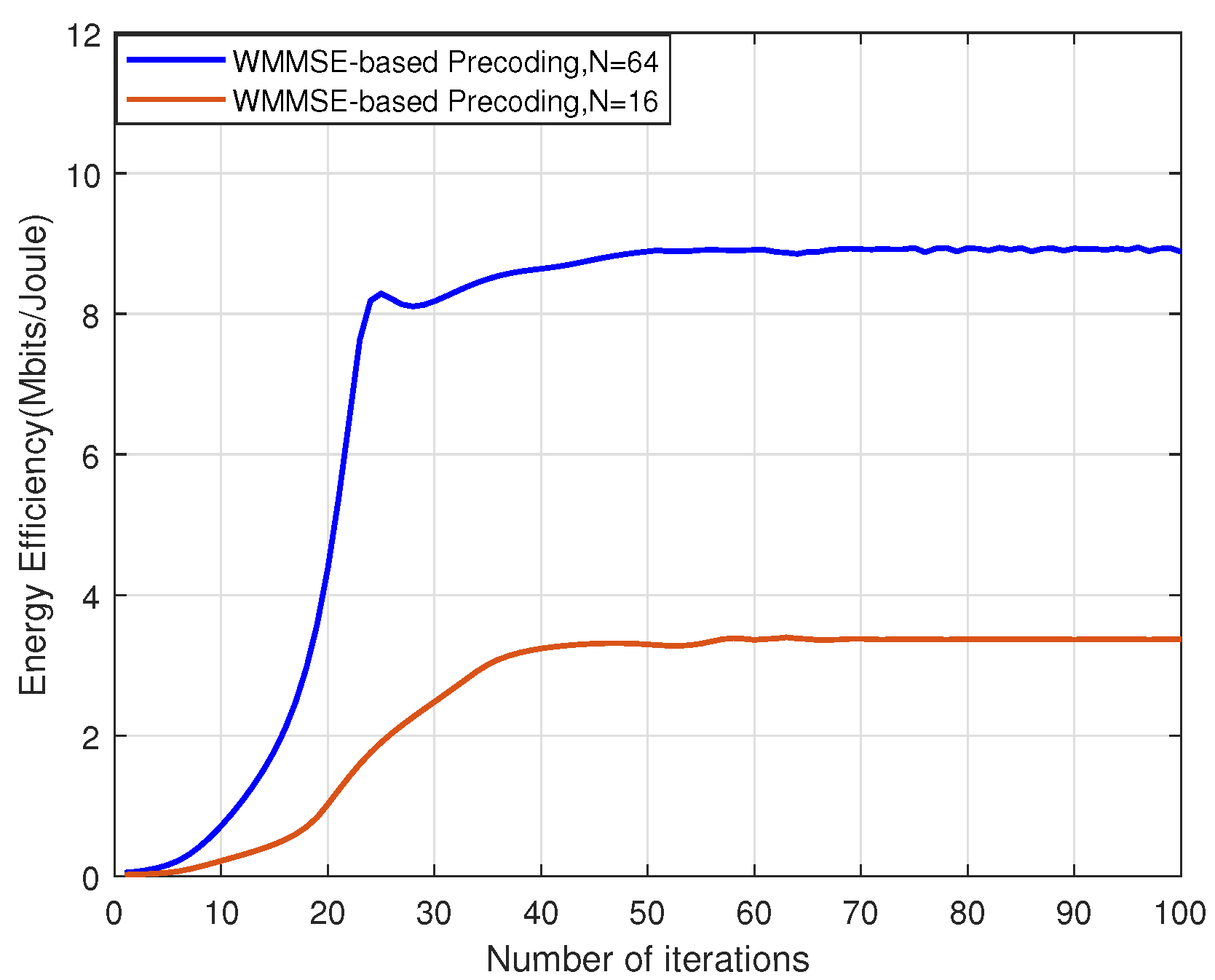
We observe the convergence of the WMMSE-based precoding algorithm. Figure 4 presents the convergence of the WMMSE-based precoding algorithm in the system with the nonlinearity of the PAs, where L and K are set as 8 and 2, respectively. This result confirms the effectiveness of the WMMSE-based precoding algorithm in CF-mMIMO-assisted LEO SATCOM systems. In addition, with a larger number of satellite antennas, the system exhibits a higher EE when the transmit power budget is saturated.
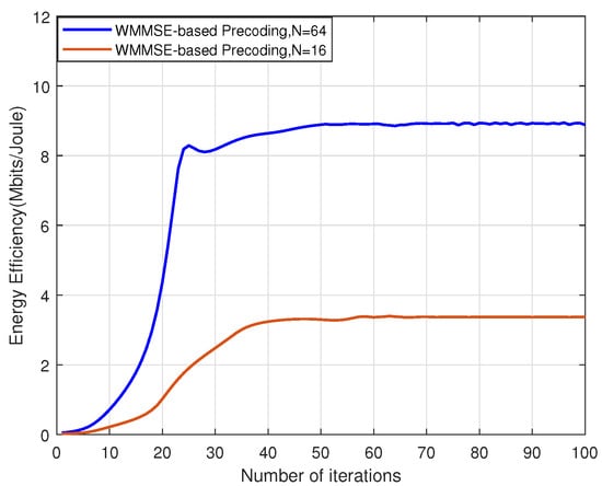
Figure 4.
EE versus the number of iterations with different satellite transmit antenna numbers and the nonlinearity of PAs.
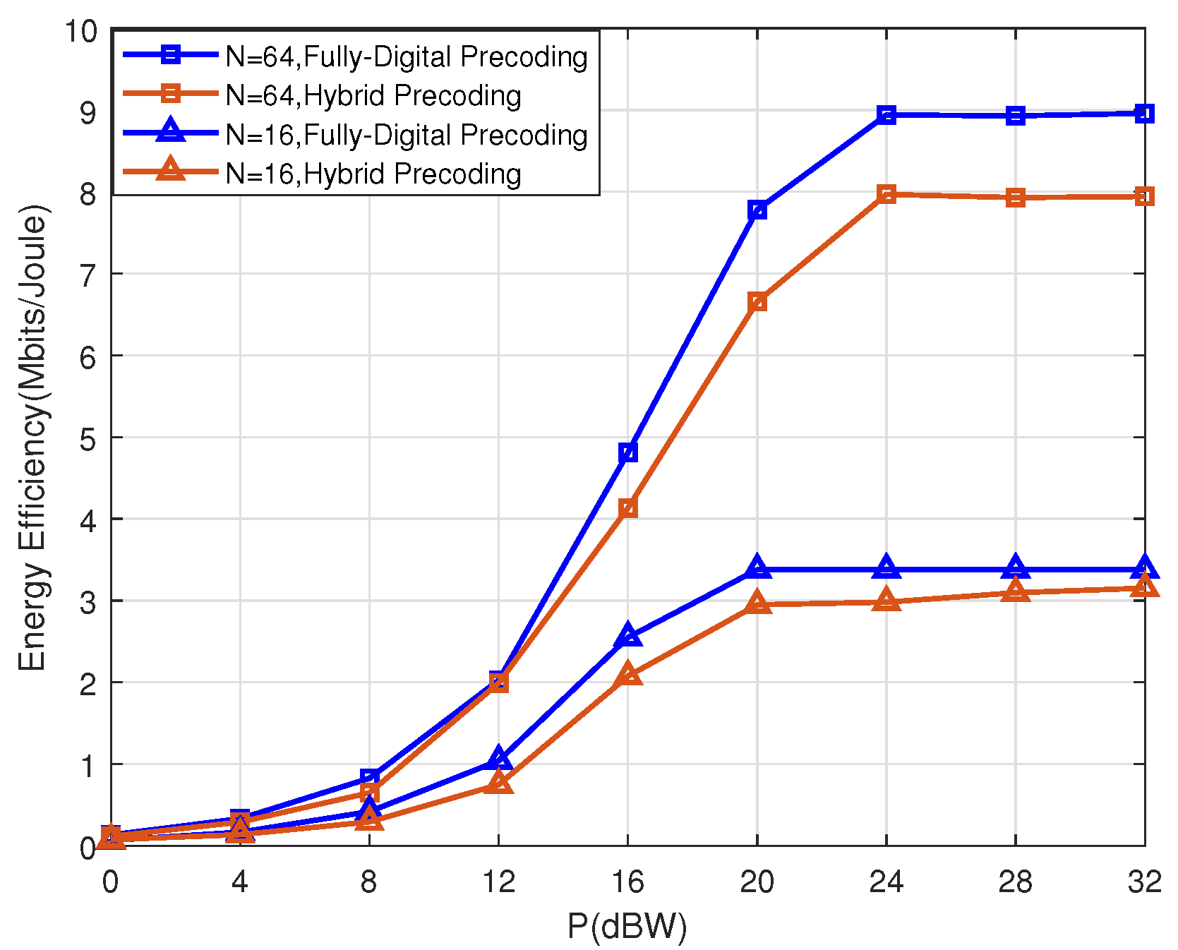
Figure 5 demonstrates the EE performance versus transmit power constraint P with different satellite transmit antenna numbers and different transmit architectures. With the nonlinearity of the PAs taken into account, the trend of the value of EE is essentially the same for different numbers of satellite antennas as the transmit power budget increases. Firstly, the EE performance for N = 64 is superior to that for N = 16. In both cases, as the transmit power budget increases, the value of EE gradually rises, eventually saturates and no longer tends to increase significantly. As the transmit power budget P gradually increases, the PA also gradually enters the saturation region, and the distortion during signal transmission increases. In addition, the EE performance of the system with hybrid precoders is marginally inferior to that with fully digital precoders.

Figure 5.
EE versus transmit power constraint P with different satellite transmit antenna numbers and different transmit architectures.
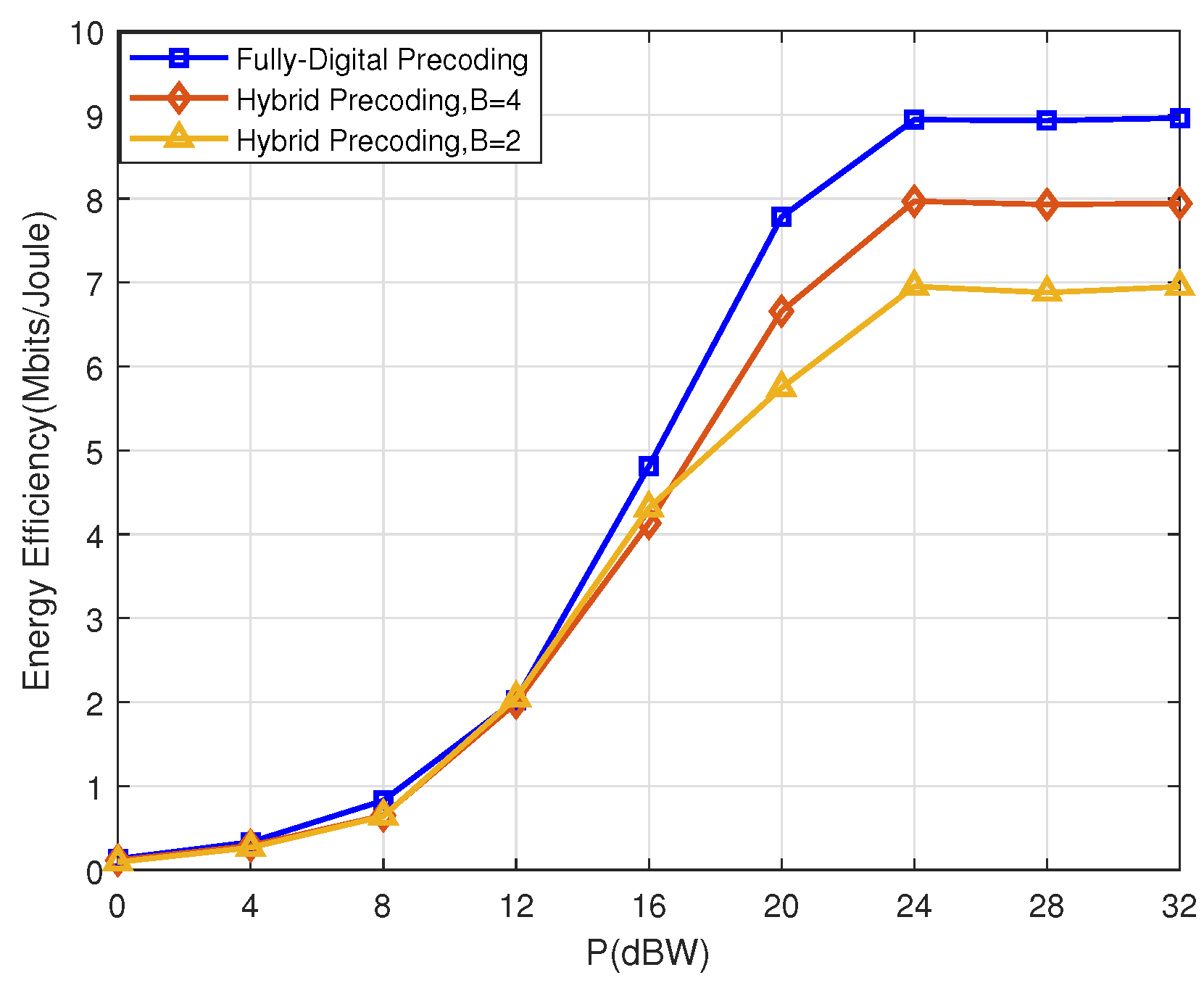
Figure 6 compares the EE performance of the hybrid precoding when for the partially connected architectures with different quantization precision. When the transmit power budget is relatively low, the EE performance is very close regardless of whether the analog precoder has a quantization accuracy of 2 or 4. When the transmit power budget is relatively high, the EE gain from higher quantization accuracy is significantly superior to the EE gain from lower quantization accuracy. The reason lies in that the EE gain due to the increase in the transmit power budget exceeds the EE loss due to higher quantization accuracy power consumption.
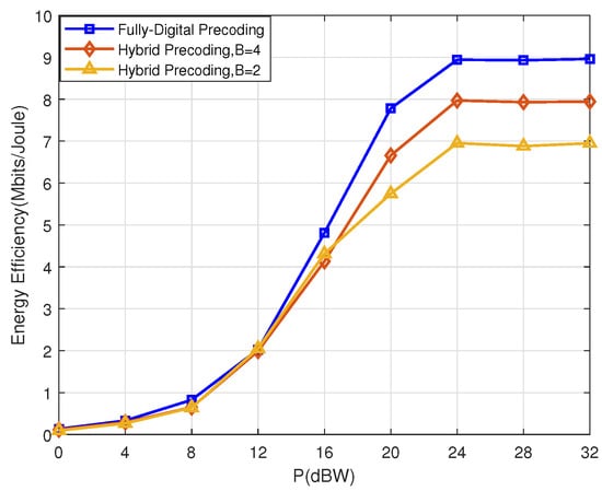
Figure 6.
EE versus transmit power constraint P for different quantization precision with .
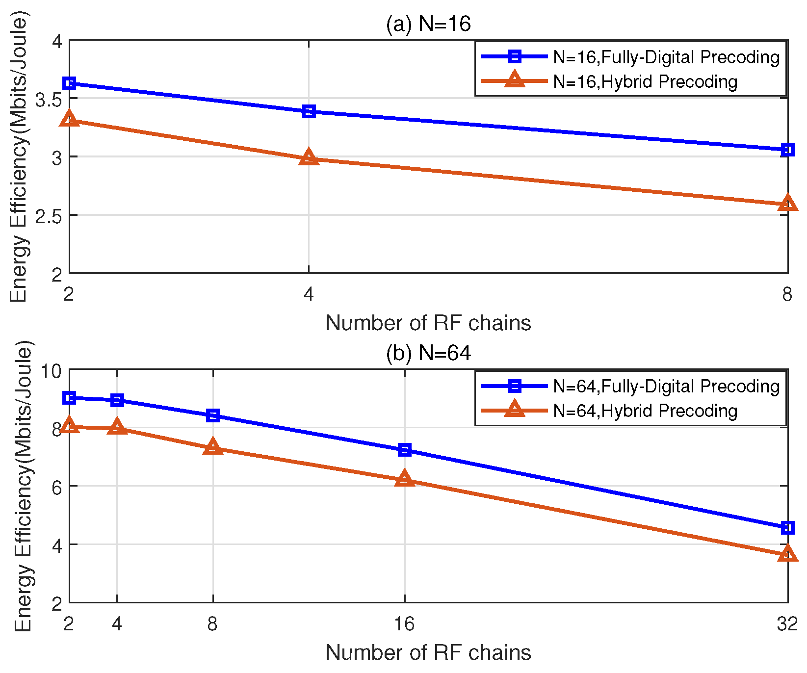
Figure 7 presents the ratio of EE performance to the number of RF chains . In the system model of this paper, the effect of power consumption of RF chains on EE is more obvious. For a fixed power budget, the total rate of data transmission increases as the number of RF chains increases. However, since the increase in power consumption is more significant, the final EE shows a gradual decrease overall. Therefore, the impact of the number of RF chains on EE is not absolute and needs to be weighed against the specific power consumption model of the system.
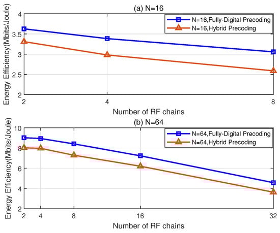
Figure 7.
EE versus with dBW for and with different transmit architectures.
6. Conclusions
This paper investigated the EE performance of a downlink CF-mMIMO-assisted LEO SATCOM system under the impact of NPAs. In the proposed system with multiple satellites and multiple GUs, we developed a user-centric SC strategy to establish the connectivity between the APs and GUs. Additionally, we formulated a hybrid precoding optimization problem aimed at maximizing EE for the partially connected architectures. To solve the problem, we first took the product of tightly coupled analog and digital matrices as a single fully digital precoder. Due to the fractional form of the EE expression, an auxiliary variable was introduced to transform the problem into a linear programming framework. Furthermore, we employed the WMMSE framework and a gradient descent method with Nesterov’s accelerated momentum to address the equivalent fully digital problem. Finally, we derived the analog and digital precoders by minimizing the Euclidean distance between the fully digital precoder and the hybrid precoder. Simulation results confirmed the convergence of the proposed WMMSE-based algorithm and demonstrated significant EE performance gains in the CF-mMIMO-assisted LEO SATCOM system. Recently, there has been growing interest in the research on programmable metasurface technology within satellite communication systems. This technology has the potential to further reduce hardware costs and demonstrates significant advantages in coverage enhancement [35,36]. In the context of future 6G networks, it is expected to drive the evolution of CF architectures towards higher energy efficiency and intelligence. We will pay more attention to this technology in future research.
Author Contributions
Conceptualization, X.M. and Y.Z.; methodology, X.M. and Y.Z.; software, X.M., Y.Z. and L.L.; validation, Y.Z. and L.L.; formal analysis, Y.Z. and L.L.; investigation, X.M. and Y.Z.; resources, X.M., Y.Z. and L.L.; writing—original draft preparation, X.M. and Y.Z.; writing—review and editing, Y.Z., L.L. and Z.Z.; funding acquisition, L.L. and Z.Z.; project administration, Y.Z. and L.L.; supervision, L.L. and Z.Z. All authors have read and agreed to the published version of the manuscript.
Funding
This work was supported in part by the National Key Research and Development Program of China under Grant 2022YFB2902100, in part by the National Science Foundation of China under Grant 62401271, in part by the Startup Foundation for Introducing Talent of Nanjing University of Information Science and Technology (NUIST) under Grant 2023r134, and in part by the Natural Science Foundation of the Higher Education Institutions of Jiangsu Province under Grant 24KJB510019.
Data Availability Statement
Data are contained within this article.
Conflicts of Interest
The authors declare no conflicts of interest.
Appendix A
Proof.
The processing procedure for digital precoder design in (36).
The power constraint in Equation (36) can be transformed into
Expanding the distortion section, we can obtain
For convenience in processing, the results of the last iteration are used in each iteration for both the analog precoder and digital precoder. Then, we need to deal with the paradigm expression part in Equation (A2), where the matrices are not easy to handle. Hence, we columnize the matrices first.
In the following, we let , , .
By adding an auxiliary variable t, the objective function can be written as
where , . Thus, Equation (A4) is equal to , where .
After dealing with the objective function, we deal with the power constraints in Equation (36) next.
Define . Thus, Equation (A5) can be expressed as
where , .
Finally, Problem (36) can be reformulated as an SDR problem:
where is the set of dimension complex Hermitian matrices, . □
References
- Dakkak, M.R.; Riviello, D.G.; Guidotti, A.; Vanelli–Coralli, A. Federated Beamforming with Subarrayed Planar Arrays for B5G/6G LEO Non-Terrestrial Networks. In Proceedings of the 2024 IEEE Wireless Communications and Networking Conference (WCNC), Dubai, United Arab Emirates, 21–24 April 2024; pp. 01–06. [Google Scholar] [CrossRef]
- Abdelsadek, M.Y.; Yanikomeroglu, H.; Kurt, G.K. Future Ultra-Dense LEO Satellite Networks: A Cell-Free Massive MIMO Approach. In Proceedings of the 2021 IEEE International Conference on Communications Workshops (ICC Workshops), Virtual, 14–23 June 2021; pp. 1–6. [Google Scholar] [CrossRef]
- Xu, Z.; Chen, G.; Fernandez, R.; Gao, Y.; Tafazolli, R. Enhancement of Direct LEO Satellite-to-Smartphone Communications by Distributed Beamforming. IEEE Trans. Veh. Technol. 2024, 73, 11543–11555. [Google Scholar] [CrossRef]
- Riviello, D.G.; De Filippo, B.; Ahmad, B.; Guidotti, A.; Vanelli-Coralli, A. Location-based User Scheduling through Graph Coloring for Cell-Free MIMO NTN Systems. In Proceedings of the 2024 Joint European Conference on Networks and Communications & 6G Summit (EuCNC/6G Summit), Antwerp, Belgium, 3–6 June 2024; pp. 652–657. [Google Scholar] [CrossRef]
- Ngo, H.Q.; Ashikhmin, A.; Yang, H.; Larsson, E.G.; Marzetta, T.L. Cell-Free Massive MIMO Versus Small Cells. IEEE Trans. Wirel. Commun. 2017, 16, 1834–1850. [Google Scholar] [CrossRef]
- Ammar, H.A.; Adve, R.; Shahbazpanahi, S.; Boudreau, G.; Srinivas, K.V. User-Centric Cell-Free Massive MIMO Networks: A Survey of Opportunities, Challenges and Solutions. IEEE Commun. Surv. Tutor. 2022, 24, 611–652. [Google Scholar] [CrossRef]
- Ngo, H.Q.; Interdonato, G.; Larsson, E.G.; Caire, G.; Andrews, J.G. Ultradense Cell-Free Massive MIMO for 6G: Technical Overview and Open Questions. Proc. IEEE 2024, 112, 805–831. [Google Scholar] [CrossRef]
- Matthaiou, M.; Yurduseven, O.; Ngo, H.Q.; Morales-Jimenez, D.; Cotton, S.L.; Fusco, V.F. The Road to 6G: Ten Physical Layer Challenges for Communications Engineers. IEEE Commun. Mag. 2021, 59, 64–69. [Google Scholar] [CrossRef]
- Riera-Palou, F.; Femenias, G.; Caus, M.; Shaat, M.; García-Morales, J.; Pérez-Neira, A.I. Enhancing Cell-Free Massive MIMO networks through LEO Satellite Integration. In Proceedings of the 2021 IEEE Wireless Communications and Networking Conference Workshops (WCNCW), Nanjing, China, 29 March–1 April 2021; pp. 1–7. [Google Scholar] [CrossRef]
- Riera-Palou, F.; Femenias, G.; Caus, M.; Shaat, M.; Pérez-Neira, A.I. Scalable Cell-Free Massive MIMO Networks with LEO Satellite Support. IEEE Access 2022, 10, 37557–37571. [Google Scholar] [CrossRef]
- Al-Hraishawi, H.; Rehman, J.u.; Chatzinotas, S. Quantum Optimization Algorithm for LEO Satellite Communications based on Cell-Free Massive MIMO. In Proceedings of the 2023 IEEE International Conference on Communications Workshops (ICC Workshops), Rome, Italy, 28 May–1 June 2023; pp. 1759–1764. [Google Scholar] [CrossRef]
- Humadi, K.; Kurt, G.K.; Yanikomeroglu, H. Distributed Massive MIMO System with Dynamic Clustering in LEO Satellite Networks. In Proceedings of the 2024 6th International Conference on Communications, Signal Processing, and Their Applications (ICCSPA), Istanbul, Turkiye, 8–11 July 2024; pp. 1–6. [Google Scholar] [CrossRef]
- You, L.; Qiang, X.; Li, K.X.; Tsinos, C.G.; Wang, W.; Gao, X.; Ottersten, B. Massive MIMO Hybrid Precoding for LEO Satellite Communications with Twin-Resolution Phase Shifters and Nonlinear Power Amplifiers. IEEE Trans. Commun. 2022, 70, 5543–5557. [Google Scholar] [CrossRef]
- Li, H.; Li, M.; Liu, Q. Hybrid Beamforming with Dynamic Subarrays and Low-Resolution PSs for mmWave MU-MISO Systems. IEEE Trans. Commun. 2020, 68, 602–614. [Google Scholar] [CrossRef]
- Vázquez, M.A.; Blanco, L.; Pérez-Neira, A.I. Hybrid Analog–Digital Transmit Beamforming for Spectrum Sharing Backhaul Networks. IEEE Trans. Signal Process. 2018, 66, 2273–2285. [Google Scholar] [CrossRef]
- Liu, Y.; Li, C.; Li, J.; Feng, L. Robust Energy-Efficient Hybrid Beamforming Design for Massive MIMO LEO Satellite Communication Systems. IEEE Access 2022, 10, 63085–63099. [Google Scholar] [CrossRef]
- Zhang, X.; Sun, S.; Tao, M.; Huang, Q.; Tang, X. Multi-Satellite Cooperative Networks: Joint Hybrid Beamforming and User Scheduling Design. IEEE Trans. Wirel. Commun. 2024, 23, 7938–7952. [Google Scholar] [CrossRef]
- Ahmad, I.; Boukhedimi, I.; Nguyen, K.; Chan, T.; Karmokar, D.; Kodithuwakkuge, J.; Ramamurthy, B. On the performance of hybrid beamforming for massive-MIMO low earth orbit satellite systems. In Proceedings of the 39th International Communications Satellite Systems Conference (ICSSC 2022), Stresa, Italy, 18–21 October 2022; Volume 2022, pp. 186–191. [Google Scholar] [CrossRef]
- Wang, L.X.; Chen, Y.F. User Selection Algorithms and Hybrid Beamforming for Power Minimization in Multiuser Massive MIMO-OFDM LEO Satellite Communication Systems. In Proceedings of the 2024 10th International Conference on Applied System Innovation (ICASI), Kyoto, Japan, 17–21 April 2024; pp. 49–51. [Google Scholar] [CrossRef]
- Mollén, C.; Gustavsson, U.; Eriksson, T.; Larsson, E.G. Spatial Characteristics of Distortion Radiated From Antenna Arrays with Transceiver Nonlinearities. IEEE Trans. Wirel. Commun. 2018, 17, 6663–6679. [Google Scholar] [CrossRef]
- Moghadam, N.N.; Fodor, G.; Bengtsson, M.; Love, D.J. On the Energy Efficiency of MIMO Hybrid Beamforming for Millimeter-Wave Systems with Nonlinear Power Amplifiers. IEEE Trans. Wirel. Commun. 2018, 17, 7208–7221. [Google Scholar] [CrossRef]
- Wu, M.; Li, M.; Zhao, M.M.; Zhao, M. A WMMSE Approach to Distortion-Aware Beamforming Design for Millimeter-Wave Massive MIMO Downlink Communication. In Proceedings of the 2022 IEEE 95th Vehicular Technology Conference: (VTC2022-Spring), Helsinki, Finland, 19–22 June 2022; pp. 1–6. [Google Scholar] [CrossRef]
- Aghdam, S.R.; Jacobsson, S.; Eriksson, T. Distortion-Aware Linear Precoding for Millimeter-Wave Multiuser MISO Downlink. In Proceedings of the 2019 IEEE International Conference on Communications Workshops (ICC Workshops), Shanghai, China, 20–24 May 2019; pp. 1–6. [Google Scholar] [CrossRef]
- Abdelsadek, M.Y.; Kurt, G.K.; Yanikomeroglu, H. Distributed Massive MIMO for LEO Satellite Networks. IEEE Open J. Commun. Soc. 2022, 3, 2162–2177. [Google Scholar] [CrossRef]
- You, L.; Li, K.X.; Wang, J.; Gao, X.; Xia, X.G.; Ottersten, B. Massive MIMO Transmission for LEO Satellite Communications. IEEE J. Sel. Areas Commun. 2020, 38, 1851–1865. [Google Scholar] [CrossRef]
- Benedetto, S.; Biglieri, E.; Daffara, R. Modeling and Performance Evaluation of Nonlinear Satellite Links-A Volterra Series Approach. IEEE Trans. Aerosp. Electron. Syst. 1979, AES-15, 494–507. [Google Scholar] [CrossRef]
- Schenk, T. Nonlinearities. In RF Imperfections in High-Rate Wireless Systems: Impact and Digital Compensation; Springer: Dordrecht, The Netherlands, 2008; pp. 185–243. [Google Scholar] [CrossRef]
- Arora, A.; Tsinos, C.G.; Shankar, B.; Chatzinotas, S.; Ottersten, B. Hybrid analog-digital precoding design for satellite systems. In Advances in Communications Satellite Systems. Proceedings of the 37th International Communications Satellite Systems Conference (ICSSC-2019), Okinawa, Japan, 29 October–1 November 2019; IEEE: Piscataway, NJ, USA; pp. 1–13. [CrossRef]
- He, S.; Huang, Y.; Jin, S.; Yang, L. Coordinated Beamforming for Energy Efficient Transmission in Multicell Multiuser Systems. IEEE Trans. Commun. 2013, 61, 4961–4971. [Google Scholar] [CrossRef]
- Shi, Q.; Razaviyayn, M.; Luo, Z.Q.; He, C. An Iteratively Weighted MMSE Approach to Distributed Sum-Utility Maximization for a MIMO Interfering Broadcast Channel. IEEE Trans. Signal Process. 2011, 59, 4331–4340. [Google Scholar] [CrossRef]
- Zhang, Y.; Huo, Y.; Wang, D.; Dong, X.; You, X. Channel Estimation and Hybrid Precoding for Distributed Phased Arrays Based MIMO Wireless Communications. IEEE Trans. Veh. Technol. 2020, 69, 12921–12937. [Google Scholar] [CrossRef]
- Zhang, Y.; Wang, D.; Huo, Y.; Dong, X.; You, X. Hybrid beamforming design for mmWave OFDM distributed antenna systems. Sci. China Inf. Sci. 2020, 63, 192301. [Google Scholar] [CrossRef]
- Yu, X.; Shen, J.C.; Zhang, J.; Letaief, K.B. Alternating Minimization Algorithms for Hybrid Precoding in Millimeter Wave MIMO Systems. IEEE J. Sel. Top. Signal Process. 2016, 10, 485–500. [Google Scholar] [CrossRef]
- Liang, L.; Xu, W.; Dong, X. Low-Complexity Hybrid Precoding in Massive Multiuser MIMO Systems. IEEE Wirel. Commun. Lett. 2014, 3, 653–656. [Google Scholar] [CrossRef]
- Lin, S.; An, J.; Gan, L.; Debbah, M.; Yuen, C. Stacked Intelligent Metasurface Enabled LEO Satellite Communications Relying on Statistical CSI. IEEE Wirel. Commun. Lett. 2024, 13, 1295–1299. [Google Scholar] [CrossRef]
- Zhi, K.; Pan, C.; Ren, H.; Wang, K.; Elkashlan, M.; Renzo, M.D.; Schober, R.; Poor, H.V.; Wang, J.; Hanzo, L. Two-Timescale Design for Reconfigurable Intelligent Surface-Aided Massive MIMO Systems with Imperfect CSI. IEEE Trans. Inf. Theory 2023, 69, 3001–3033. [Google Scholar] [CrossRef]
Disclaimer/Publisher’s Note: The statements, opinions and data contained in all publications are solely those of the individual author(s) and contributor(s) and not of MDPI and/or the editor(s). MDPI and/or the editor(s) disclaim responsibility for any injury to people or property resulting from any ideas, methods, instructions or products referred to in the content. |
© 2025 by the authors. Licensee MDPI, Basel, Switzerland. This article is an open access article distributed under the terms and conditions of the Creative Commons Attribution (CC BY) license (https://creativecommons.org/licenses/by/4.0/).