Article

A Wearable Dual-Band Magnetoelectric Dipole Rectenna for Radio Frequency Energy Harvesting

by
Xin Sun
,
Jingwei Zhang
*,
Wenjun Wang
and
Daping He
School of Physics and Mechanics, Wuhan University of Technology, Wuhan 430070, China
*
Author to whom correspondence should be addressed.
Electronics 2025, 14(7), 1314; https://doi.org/10.3390/electronics14071314
Submission received: 27 February 2025 / Revised: 21 March 2025 / Accepted: 25 March 2025 / Published: 26 March 2025
(This article belongs to the Section Microwave and Wireless Communications)

Abstract

:
This article presents a novel, compact, and flexible dual-band magnetoelectric dipole rectenna designed for radio frequency (RF) energy harvesting. The rectenna consists of a unique antenna structure, combining electric and magnetic dipoles to create unidirectional radiation patterns, minimizing interference from the human body. The rectifier is integrated with the antenna through conjugate matching, eliminating the need for additional matching circuits, reducing circuit losses, minimizing design complexity, and improving conversion efficiency. The proposed rectenna utilizes a flexible graphene film as the radiating element, which offers excellent conductivity and corrosion resistance, enabling conformal operation in diverse scenarios. Simulation and experimental results show that the rectenna operates effectively at 3.5 GHz and 4.9 GHz, achieving peak conversion efficiencies of 53.43% and 43.95%, respectively, at an input power of 4 dBm. The simulated and measured results achieved good agreement. The rectenna maintains stable performance under various bending conditions, demonstrating its suitability for flexible, wearable RF energy-harvesting systems.

1. Introduction

The Internet of Things (IoT) interconnects everything with a vast number of wireless sensors [1], enabling applications such as healthcare monitoring, location tracking, smart homes, and industrial automation [2]. The rapid growth of IoT technologies has significantly increased the demand for wearable sensors. However, battery-powered sensors present several challenges, such as limited battery life, bulkiness, weight, and high maintenance costs. Consequently, relying on traditional batteries to power sensors restricts the overall growth and expansion of the IoT. Due to the limitations of conventional batteries, many researchers have explored alternative energy sources from the environment, including piezoelectric [3], vibration [4], and microwave energy harvesting [5,6,7]. These energy-harvesting technologies can capture energy for low-power applications. Microwave energy harvesting has gained significant attention due to its ability to deliver power over long distances and lack of environmental interference. Several studies have reported the conversion of ambient microwave energy into direct current (DC), providing an energy solution for wearable sensors [8,9,10,11,12,13,14,15,16,17,18,19,20]. The core element of a microwave energy-harvesting system is the rectenna, which can capture and convert microwave energy. To meet the specific requirements of wearable sensors, it is crucial to design rectennas that are both flexible and capable of maintaining stable operating performance under dynamic environments.
Recent research on wearable rectenna designs has been reported in the literature [21,22,23,24,25,26]. However, many of these designs have high levels of backward radiation, which reduces the system conversion efficiency due to the electromagnetic properties of the human body. Consequently, high body isolation is essential to ensure stable radiation properties and efficient energy conversion. Unidirectional radiating rectennas with high front-to-back ratios (FBRs) have been reported to provide the necessary body isolation [27,28,29,30,31,32]. Rectennas have been explored using a metal plate to reflect backward-radiating beams, achieving unidirectional radiation [28]. In addition, artificial magnetic conductor structures have been utilized in rectenna design to achieve unidirectional radiation [30]. However, these rectennas operate at a single frequency. In ambient environments, the available power is low, and harvesting energy from only one frequency is insufficient. There is a growing need for wearable multiband unidirectional rectennas to overcome these limitations. Multiband designs can capture energy across multiple frequency ranges, resulting in higher power reception.
Furthermore, the environment in which wearable rectennas are used includes high humidity and mild corrosion from human skin, requiring that rectennas exhibit high corrosion resistance. Materials with flexibility, high electrical conductivity, high mechanical durability, and corrosion resistance are essential to address this challenge. Traditional rectennas are constructed with thin metallic films. These metallic films exhibit poor mechanical endurance and are prone to oxidation in weakly corrosive environments [33]. Graphene exhibits excellent electrical conductivity, mechanical flexibility, and remarkable corrosion resistance. These properties render it an ideal candidate for wearable applications. Recent studies have shown that highly conductive graphene-based films (CGFs) are well suited for wearable devices [34,35,36] due to their mechanical stability and high corrosion resistance.
This paper proposes a novel dual-band magnetoelectric dipole rectenna that combines a high FBR and a low profile, utilizing CGFs. The antenna design features C-shaped slots to enhance the radiation characteristics, achieving high FBRs at both 3.5 GHz and 4.9 GHz. A compact rectifier circuit is integrated with the antenna, enabling operation in the 5 G frequency bands. The overall dimensions of the rectenna are 56 × 47 × 0.536 mm3. The rectenna achieves maximum conversion efficiencies of 53.43% at 3.5 GHz and 43.95% at 4.9 GHz when the input power is 4 dBm. Experimental results demonstrate reliable performance on human-body models, even under bending conditions. The proposed design highlights the potential of CGF-based rectennas for efficient, flexible, and wearable energy-harvesting applications.
This paper is organized as follows. Section 2 describes the characterization of the high CGFs. Section 3 introduces the design and performance of the dual-band magnetoelectric dipole antenna. Section 4 presents the design and performance of the rectifier circuit and rectenna system. Finally, Section 5 summarizes the conclusions.

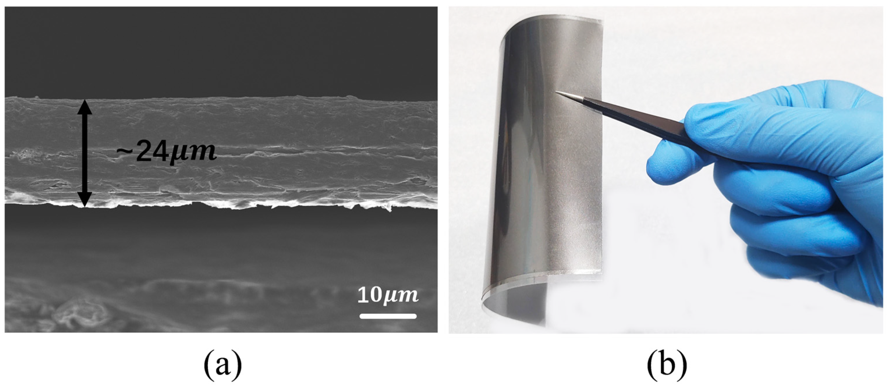
2. Characterization of the High CGFs

Using high CGFs for antenna fabrication offers advantages over traditional metallic materials in wearable applications. Notably, CGFs exhibit high flexibility, adapting well to various curvatures, and excellent corrosion resistance, making them suitable for operation in weak acidic and alkaline environments encountered on the human body [8]. The high CGFs were fabricated in our laboratory. First, graphene oxide (GO) (Wuxi Chengyi Education Technology Co., Ltd., Wuxi, China) was diluted to 10–20 mg/mL in ultrapure water to form a GO suspension. The suspension was then stirred and evenly spread onto a PET film pre-coated with silicone oil to facilitate easy removal. After evaporative drying at room temperature for 24 h, the film underwent annealing at 1300 °C for 2 h and 3000 °C for 1 h in an argon atmosphere, forming a highly conductive graphene-based film. Finally, rolling compression was applied to achieve densely packed CGFs.
Figure 1 illustrates the cross-sectional scanning electron microscopy (SEM) image of the CGF sample and a digital photograph demonstrating its flexibility. The SEM image was obtained with a JEM6700 scanning electron microscope (JEOL Co., Ltd., Tokyo, Japan), revealing a thickness of approximately 24 µm for the CGF. The electric conductivity of 1.1 × 10⁶ S/m and the sheet impedance of 35 mΩ were measured using the four-probe method. The conductivity of the CGF is comparable to that of metallic materials, indicating its potential for antenna applications. Moreover, the antenna was precisely patterned using an LPKF laser machine (LPKF Laser & Electronics AG, Garbsen, Germany) to create our designed patterns.

3. Antenna Design

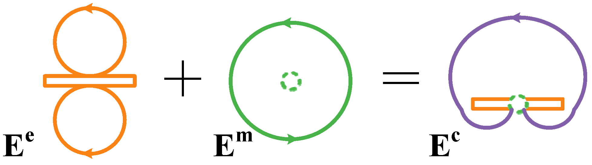
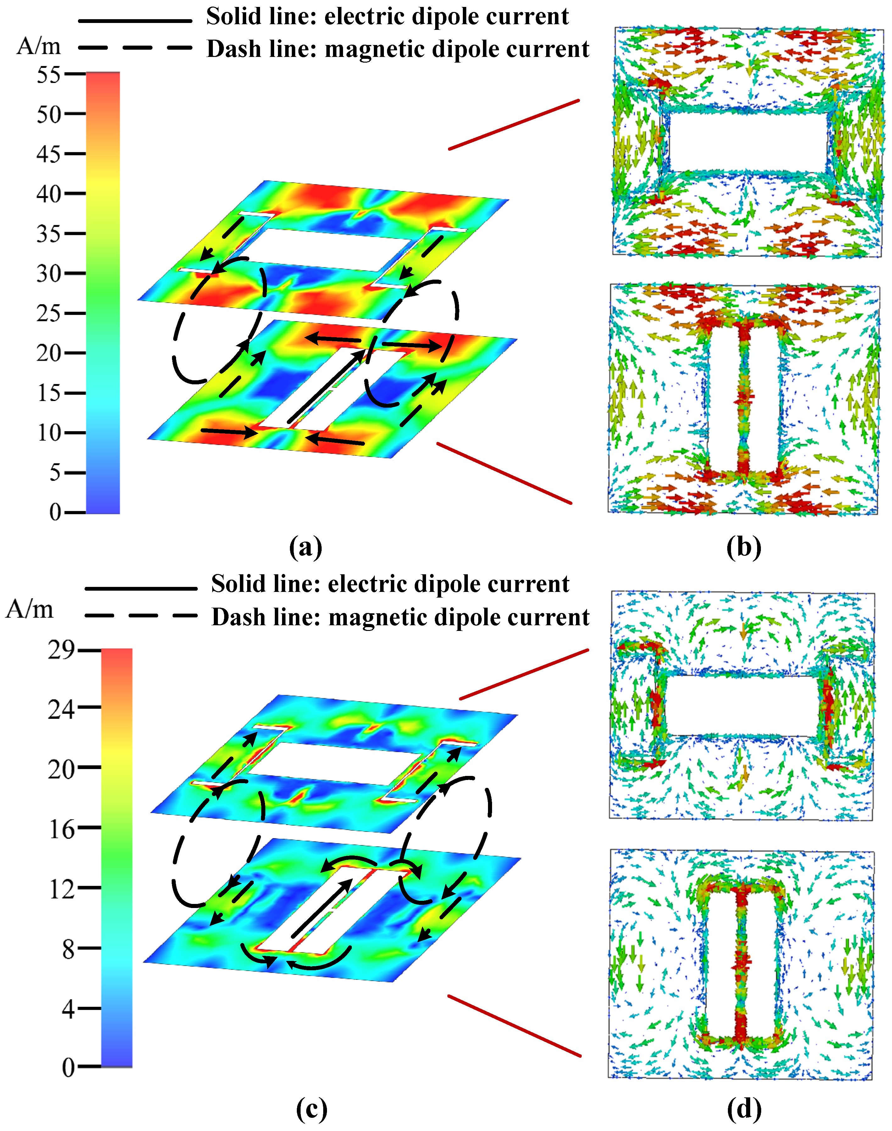
3.1. Antenna Configuration and Operating Mechanisms

The geometry of the low-profile dual-band magnetoelectric dipole antenna is illustrated in Figure 2. The antenna is a three-layer structure, including a flexible Polydimethylsiloxane (PDMS) substrate with a thickness of 0.5 mm, a relative permittivity of 2.7, and a loss tangent of 0.013, and two CGF radiators mounted on the top and bottom of the substrate. The top radiator has a rectangular shape with two C-shaped slots designed to achieve magnetic dipole radiation. In addition, an H-shaped slot is etched on the bottom radiator to generate electric dipole radiation. The gap within the H-shaped slot can also be connected with a rectifier for further integration. The antenna design was simulated and optimized using Computer Simulation Technology (CST) Microwave Studio, with the key design parameters listed in Table 1.
The proposed dual-band antenna operates at 3.5 GHz and 4.9 GHz, which fall within the 5 G communication spectrum. When the electric and magnetic dipoles have the same excitation amplitude and their phase centers overlap, the main beam direction formed by them is perpendicular to the orientation of the dipoles [37]. As shown in Figure 3, the electric fields due to the electric dipole, magnetic dipole, and electromagnetic dipole are labeled as Ee, Em, and Ec. The antenna generates a unidirectional magnetoelectric dipole by combining the electric and magnetic dipoles. When the excitation amplitudes of the two dipoles are equal, the front-to-back ratio (FTB) of the directional radiation pattern is theoretically infinite, indicating perfectly unidirectional radiation. If the amplitude difference between these two dipoles is significantly large, the FTB tends towards 0 dB, leading to omnidirectional radiation.
The simulation was carried out using CST Microwave Studio, where the rectenna structure was modeled with a graphene-based conductive layer on a flexible dielectric substrate, as shown in Figure 2. Figure 4 describes the surface current amplitude and vector map at the two operating bands. At 3.5 GHz, a strong current flows on the bottom radiator, concentrating around the feeding structure and the long side edge. This behavior resembles a traditional full-wavelength electric dipole. Meanwhile, an opposite current is coupled on the top surface of the radiator, as shown in Figure 4a,b. Two pairs of opposite currents on the top and bottom surfaces form a loop current path on the short side, leading to magnetic resonance. The symmetric distribution of these loop currents aligns the phase center of the magnetic resonance with the electric dipole. Since both dipoles exhibit similar excitation amplitudes, the forward radiation pattern is significantly enhanced, while the backward radiation is suppressed, resulting in unidirectional magnetoelectric dipole radiation.
At 4.9 GHz, the current distribution is concentrated along the edge of the H-shaped slot, working as a half-wavelength electrical dipole, as shown in Figure 4c,d. Strong coupling between the C-shaped and rectangular slots causes a current focus on the C-shaped slot at the top radiator. Similar to 3.5 GHz, two loop currents form on the short sides, contributing to magnetic dipole radiation. These two dipoles work together to generate unidirectional magnetoelectric radiation at 4.9 GHz. This radiation mechanism ensures a high FBR and stable unidirectional performance, making the antenna well suited for wearable applications.

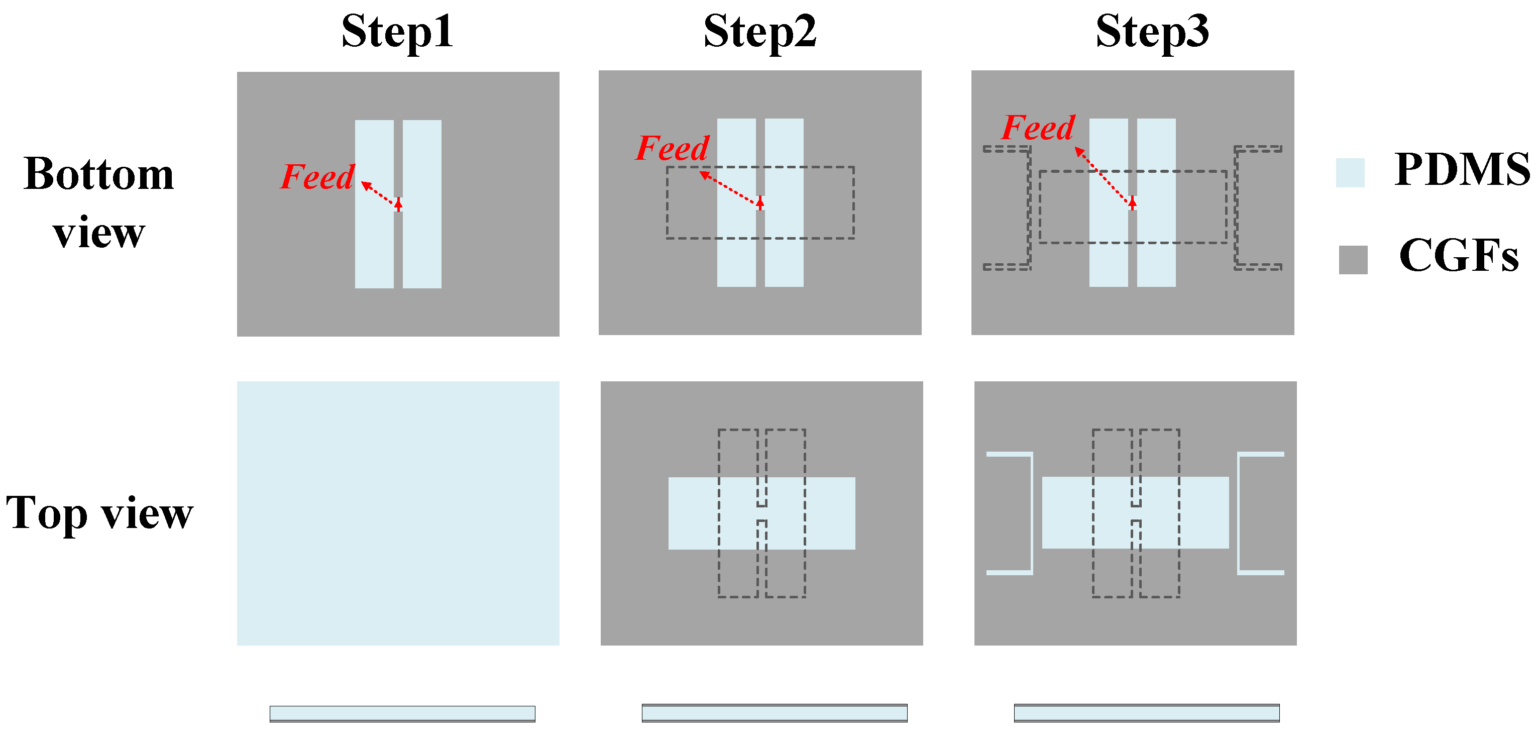
3.2. Design Process and Parametric Study

Based on the radiation mechanism of the magnetoelectric dipole, the design process is divided into three key steps, as illustrated in Figure 5: Step 1, Step 2, and the final proposed design in Step 3. Each step progressively refines the antenna layout to optimize its performance for the desired frequency bands and radiation characteristics.
The design process begins with Step 1, where an electric dipole generates radiation at the 3.5 GHz band. The basic dipole design principle follows [38], with significant modifications and optimizations to meet the unique requirements of this work. The current distribution and radiation pattern for this step are shown in Figure 6.
Step 2 introduces a radiating layer with a rectangular slot above the electric dipole (Step 1) to achieve a magnetoelectric dipole. This step uses current coupling from the electric dipole to generate a magnetic dipole (loop current), which is crucial for forming the desired radiation characteristics. Figure 7a shows a strong current flowing on the bottom radiator at 3.5 GHz. The current is concentrated around the feeding structure and along the long side edge, primarily as a traditional full-wavelength electric dipole. Figure 7a,b show that two pairs of opposite currents (loop currents) are formed on the short side of the radiator, generating a magnetic resonance. Since the phase center of the magnetic resonance closely aligns with the electric dipole, magnetoelectric dipole radiation is achieved, as shown in Figure 7c.
At 4.9 GHz, as shown in Figure 7d, a strong current flows on the bottom radiator, concentrating on the edge of the H-shaped slot. This current distribution represents a half-wavelength electrical dipole. However, Figure 7e shows that no loop current paths form on the short side of the radiator. As a result, the radiation pattern becomes omnidirectional, as shown in Figure 7f, due to the lack of a magnetic dipole contribution.
To produce a loop current path on the short side, two C-shaped slots are introduced in Step 3. As shown in Figure 8a,b, the addition of these slots has minimal influence on the current distribution at 3.5 GHz. However, the C-shaped slots induce two pairs of opposite parallel currents on both the top and bottom radiators at 4.9 GHz (Figure 8d,e). As shown in Figure 8f, this current distribution at 4.9 GHz enables the formation of a unidirectional magnetoelectric dipole.
Moreover, the color difference in the vector arrows corresponding to the electric dipole and magnetic dipole reveals the difference in amplitude. Due to the minimal amplitude difference between the electrical and magnetic dipoles, the FBR at 4.9 GHz is notably improved compared to that at 3.5 GHz. Despite some amplitude disparity at 3.5 GHz, the radiation pattern maintains an FBR greater than 10 dB, ensuring stable unidirectional radiation characteristics.
By carefully tuning the position and dimensions of the etched slots, the amplitudes of the magnetic and electric dipoles can be more closely matched, thereby enhancing the FBR of the antenna. A higher FBR reduces backward radiation, which is crucial for minimizing interference from the human body in wearable applications. A suboptimal FBR leads to substantial absorption of backward radiation by biological tissues, resulting in not only electromagnetic energy dissipation but also significant variations in the antenna’s input impedance. These variations are attributed to the mismatching between the antenna and the rectifier, ultimately leading to an operational frequency band shift and degradation of the overall system efficiency. Consequently, optimizing the FBR is essential for enhancing the antenna’s performance in these applications. Key design parameters were carefully optimized, as shown in the parametric studies in Figure 9.
As shown in Figure 9a, increasing the width of the rectangular slot (W2) enhances the FBR at 3.5 GHz, while at 4.9 GHz, the highest FBR is achieved when W2 is 12.5 mm. To balance the performance across both bands, W2 was set to 12.5 mm. Figure 9b reveals that the length of the rectangular slot (L2) has minimal impact on the FBR at 4.9 GHz, but at 3.5 GHz, an L2 of 33 mm is required to maintain a high FBR. Thus, an L2 of 33 mm was chosen to optimize the dual-band performance. In Figure 9c, the length of W4 is optimized, which affects the magnetic dipole at 4.9 GHz. It is evident that W4 mainly influences the FBR at 4.9 GHz but not at 3.5 GHz. With a peak occurring at 23.4 mm, a W4 of 23.4 mm was selected as the optimized value. Moreover, the gap S5 between the rectangular and C-shaped slots plays a crucial role in controlling the coupling current on the C-shaped slots. Figure 9d illustrates that reducing the gap S5 enhances the coupling between the rectangular and C-shaped slots, improving the FBR. However, excessive coupling can disrupt the performance. A tradeoff is achieved at S5 = 1.5 mm, where the amplitude difference between the electric and magnetic dipoles is minimized, ensuring stable unidirectional radiation. These optimization steps highlight the importance of fine-tuning the antenna geometry to achieve high performance, making the antenna well suited for wearable applications.

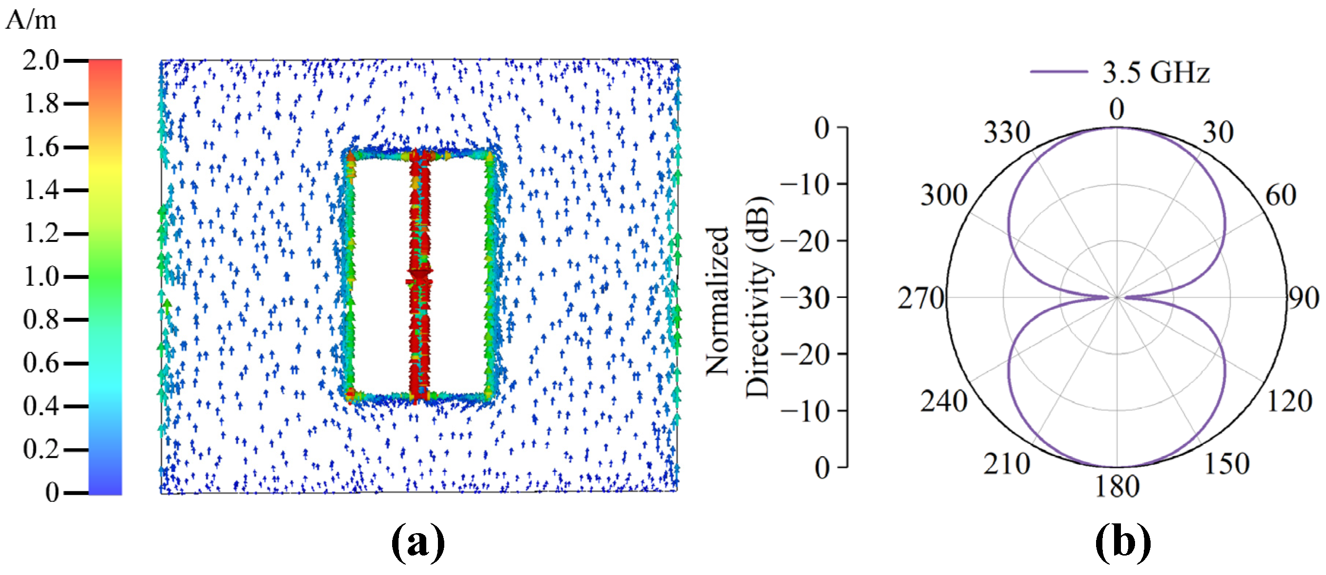
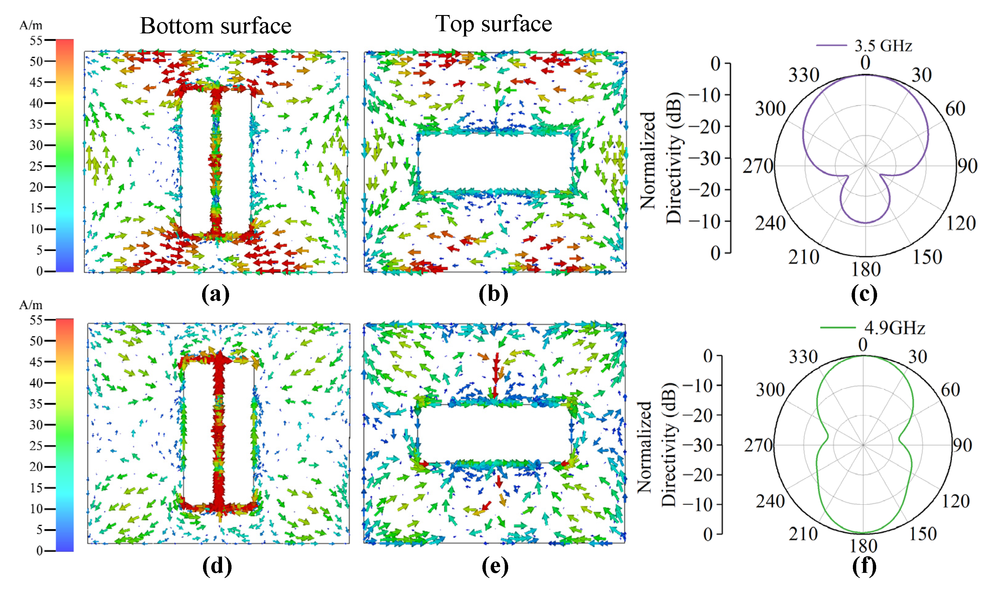
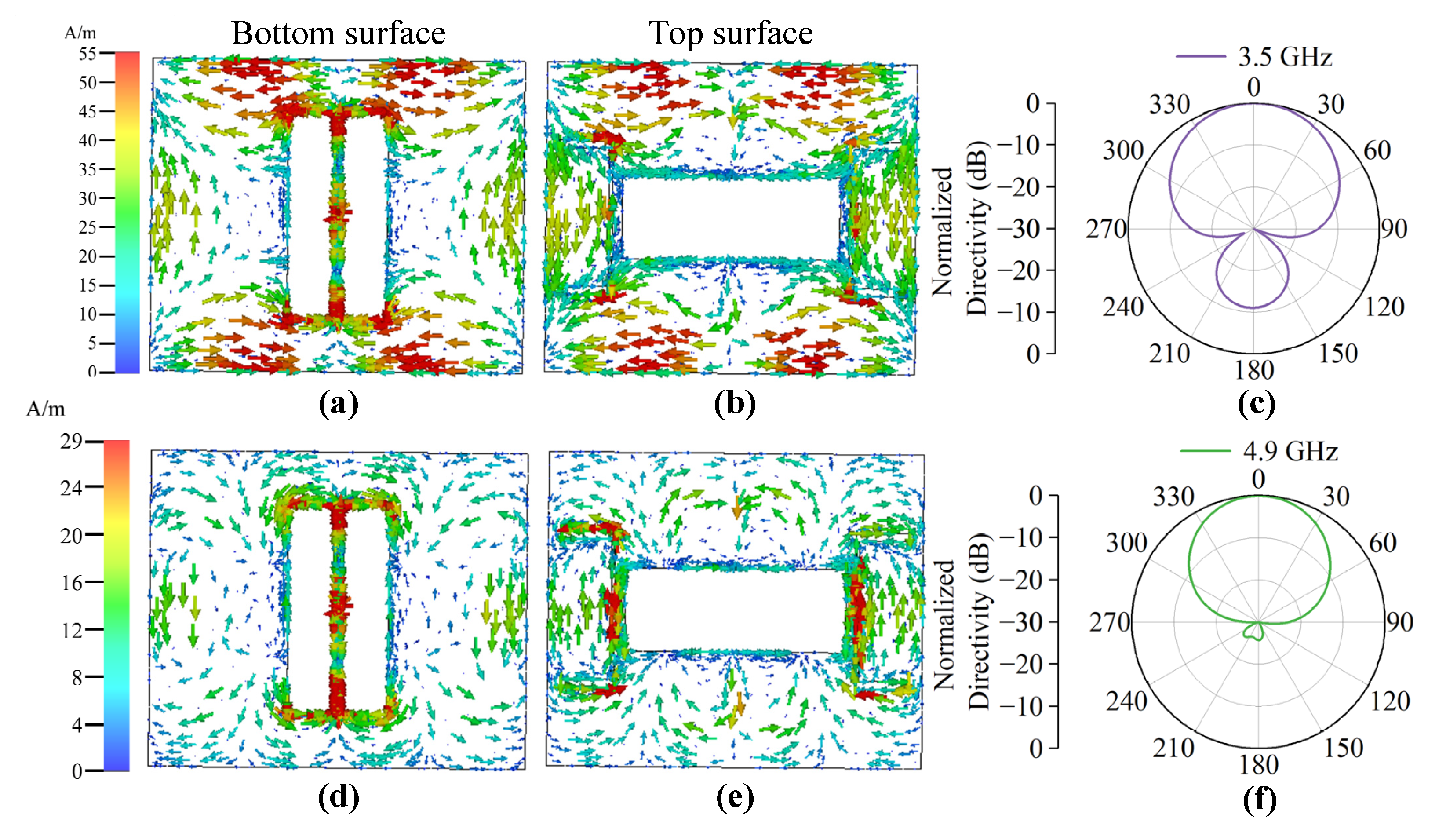
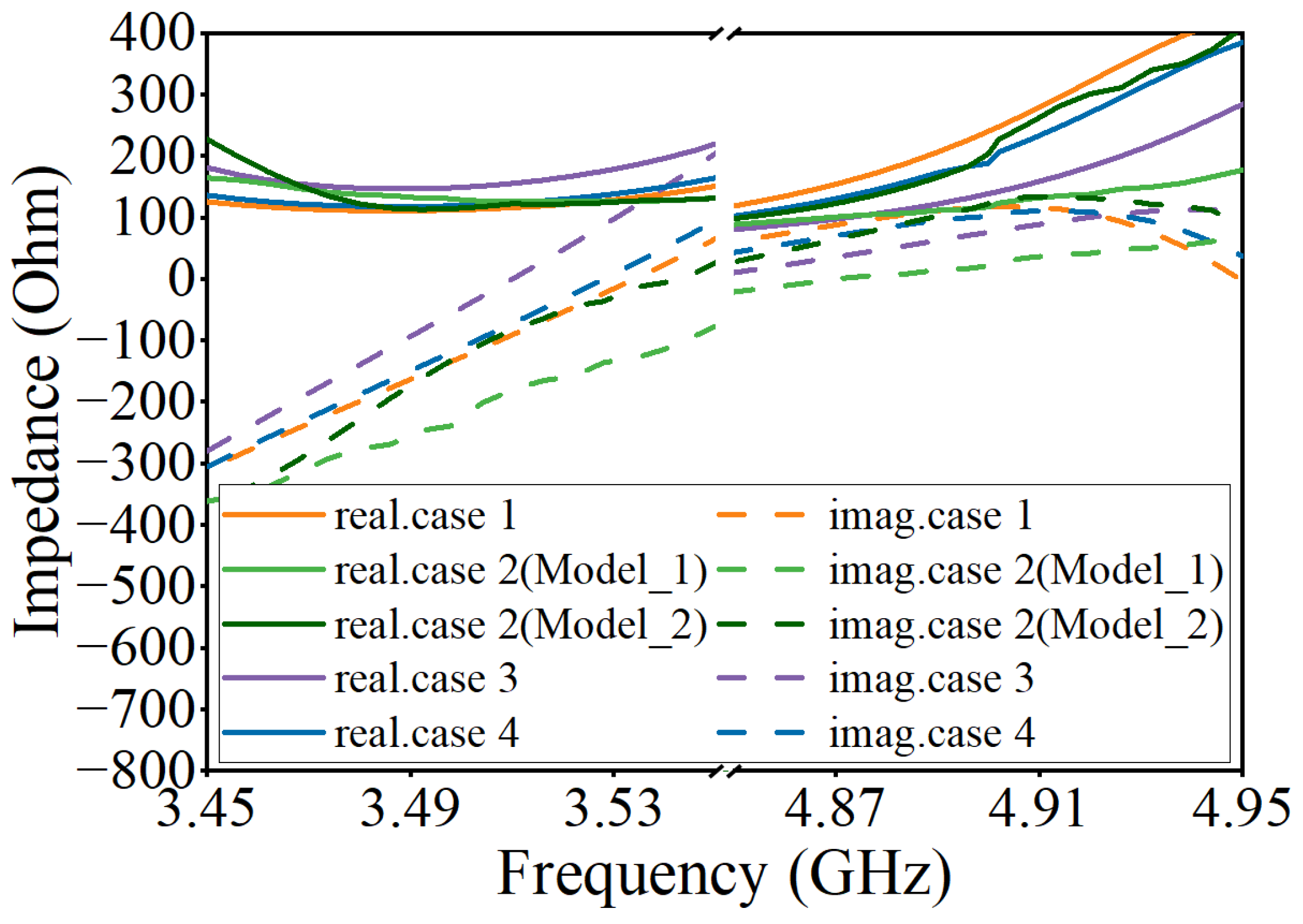
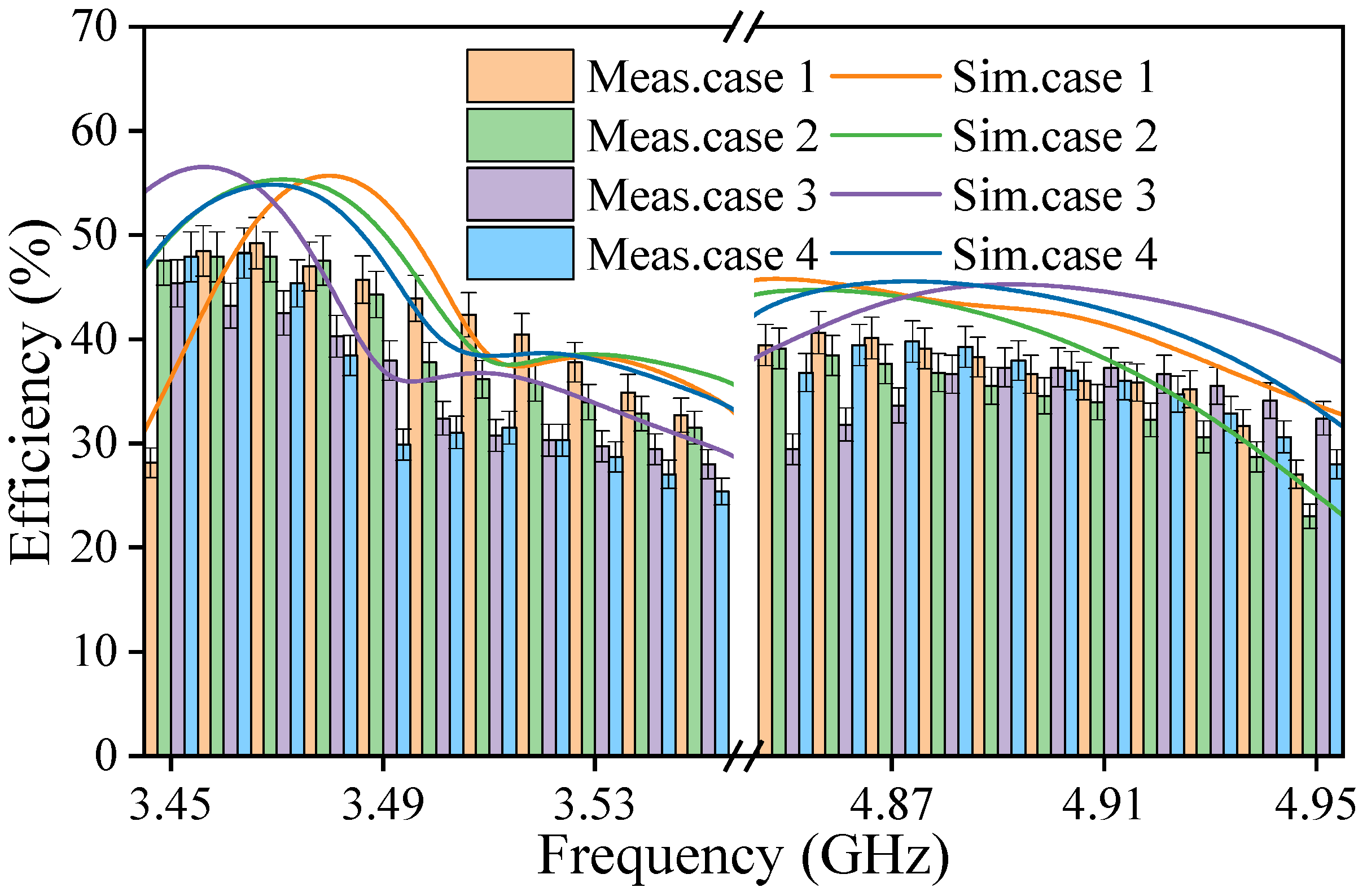
3.3. Results and Discussion

Achieving stable and directional radiation patterns on the body is essential for an efficient wearable rectenna. Various operating conditions were simulated and analyzed to assess the antenna’s performance in wearable scenarios, as illustrated in Figure 10. Case 1 represents the antenna in free space, Case 2 considers the antenna placed on a human tissue model, Case 3 represents the antenna bent with a 20 mm curvature, and Case 4 considers the antenna bent with a 40 mm curvature.
A simplified human model, with dimensions of 90 mm × 90 mm × 13 mm, was employed to represent a human body segment in Case 2. This model comprises three layers corresponding to the skin, fat, and muscle. The geometric characteristics of the human body exhibit variations depending on body composition, particularly between individuals with different fat-to-muscle ratios. The individual differences may affect the antenna’s radiation performance. To investigate this effect, we simulated the antenna performance on two distinct human models representing contrasting body types: one with a higher fat content [39] and the other with a leaner composition [40]. The detailed geometric parameter properties of these two models are presented in Table 2.
The simulated input impedance of the proposed antenna under various operating conditions was also investigated and is shown in Figure 11. The input impedance is critical in impedance matching between the antenna and rectifier. The results indicate that the input impedance exhibits minor differences across different scenarios. A tradeoff among the four cases was considered to minimize the impedance mismatch in the rectenna. The average impedance values were used as the source impedance in the rectifier design.
As shown in Figure 12, the normalized radiation pattern illustrates that the antenna maintains stable unidirectional radiation characteristics at both operating frequency bands under different working conditions, even considering individual differences (see Figure 12b). In addition, the differences between co-polarization and cross-polarization are more than 30 dB, further emphasizing the directional radiation performance. This stability is crucial for wearable applications, as it ensures consistent performance despite the dynamic environment of the human body.
The FBRs across both operational frequency bands under different curvature conditions were simulated to investigate the impact of bending, as shown in Figure 13. The simulation data reveal that the antenna maintains excellent unidirectional radiation performance (with FBR > 10 dB) in both the 3.5 GHz and 4.9 GHz bands when the bending radius exceeds 20 mm. However, when the radius is smaller than 20 mm, the FBR at both frequencies falls sharply. When the radius is reduced to 18 mm, the FBR at 3.5 GHz drops below 10 dB. The FBR at 4.9 GHz drops below 10 dB as the bending radius decreases to 15 mm. This degradation results in the distortion of unidirectional radiation, making the antenna unsuitable for wearable applications. It was observed that the antenna may not perform effectively in high-curvature regions such as the palms and neck. These findings have important implications for practical wearable applications. Due to curvature limitations, the antenna cannot be effectively deployed in high-curvature areas such as palms and the neck. However, it maintains stable radiation performance in relatively flat areas of the body, including the arms and back, ensuring reliable operation in practical wearable scenarios.
Furthermore, the specific absorption rate should also be considered to ensure radiation safety. The specific absorption rate was simulated with an input power of 5 dBm, and the results are presented in Figure 14. The maximum 1 g specific absorption rate values at 3.5 GHz and 4.9 GHz were 0.085 W/kg and 0.131 W/kg, respectively. They are well below the 1.6 W/kg limit for 1 g of human tissue. The maximum 10 g specific absorption rate values are 0.04 W/kg at 3.5 GHz and 0.0711 W/kg at 4.9 GHz, which are less than the 2 W/kg limit set by the FCC and ICNIRP. The radiation efficiency of the antenna in different operation situations is shown in Table 3. From the result, the radiation efficiency of the GCF-based antennas is slightly lower than that of the copper ones due to the reduced electrical conductivity of the CGF. It is clear that the proposed rectenna has a stable conversion efficiency under various operational conditions, which is important in practice.

4. Rectenna System

4.1. Rectifier Configuration

The layout of the rectifier is shown in Figure 15. To be integrated into the wearable antenna, the rectifier is designed for conjugate matching with the antenna, reducing the overall size. The rectifier is mounted on a PDMS substrate and consists of a Schottky diode (SMS7630), two capacitors, an inductor, and a load resistance. A single-shunt diode configuration is used to achieve a simple structure with high conversion efficiency. A series RF choke (L) is placed between the diode and capacitor C2 to block RF signals generated by the diode and tune the input impedance of the rectifier circuit. The rectifier is highly compact, with a total length of 2.2 mm × 6 mm. The rectifier was designed and simulated using Advanced Design System (ADS) 2018 software. The diode was modeled using its packaging parasitic inductance and capacitance to reduce the effect of the packaging. In addition, a Touchstone S1P file was imported into the ADS simulation to ensure proper impedance matching, which contained the average impedance of the proposed wearable antenna. Based on multilayer stacking technology, the rectenna is electrically connected to the power export circuit through a via-hole, which links the output terminals of the rectifier circuit to the external system. These via-holes provide an efficient electrical path for transferring the harvested energy from the rectifier to the external systems, such as the power management system.
To investigate the impact of the output load and inductor values, simulations and optimizations were carried out in ADS, and the results are shown in Figure 16 and Figure 17. The results were obtained under an input power level of 0 dBm. The conversion efficiency (η) is calculated using the following equation:
η = V 2 P 0   ×   R
where V is the output voltage, R is the load resistance, and P0 is the input power.
In Figure 16, the conversion efficiency at 3.5 GHz increases with the output load and reaches a peak of 56.3% at 550 Ω. At 4.9 GHz, the conversion efficiency also improves with increasing output load, but the rate of improvement slows significantly after 550 Ω. Consequently, there is a tradeoff between the two operational frequencies, and a load resistance of 550 Ω was selected. Figure 17 illustrates the reflection coefficient (S11) and the RF-to-DC conversion efficiency as a function of the frequency. The reflection coefficient is important to indicate the matching performance between the rectifier and the antenna. From the result, the inductor L significantly impacts the rectifier performance at 3.5 GHz, influencing both the S11 and the conversion efficiency. However, at 4.9 GHz, changing the inductor value significantly influences the input impedance, but has little effect on the conversion efficiency. The optimal component values are listed in Table 4.
To further verify the rectifier’s performance in wearable applications, we simulated the S11 of the rectifier under different working conditions, as shown in Figure 18. The reflection coefficients for various operating conditions remain below −10 dB within the target frequencies. It is shown that the rectifier is well matched with the antenna. Impedance changes under different conditions cause slight frequency shifts, but these shifts are still within acceptable limits.

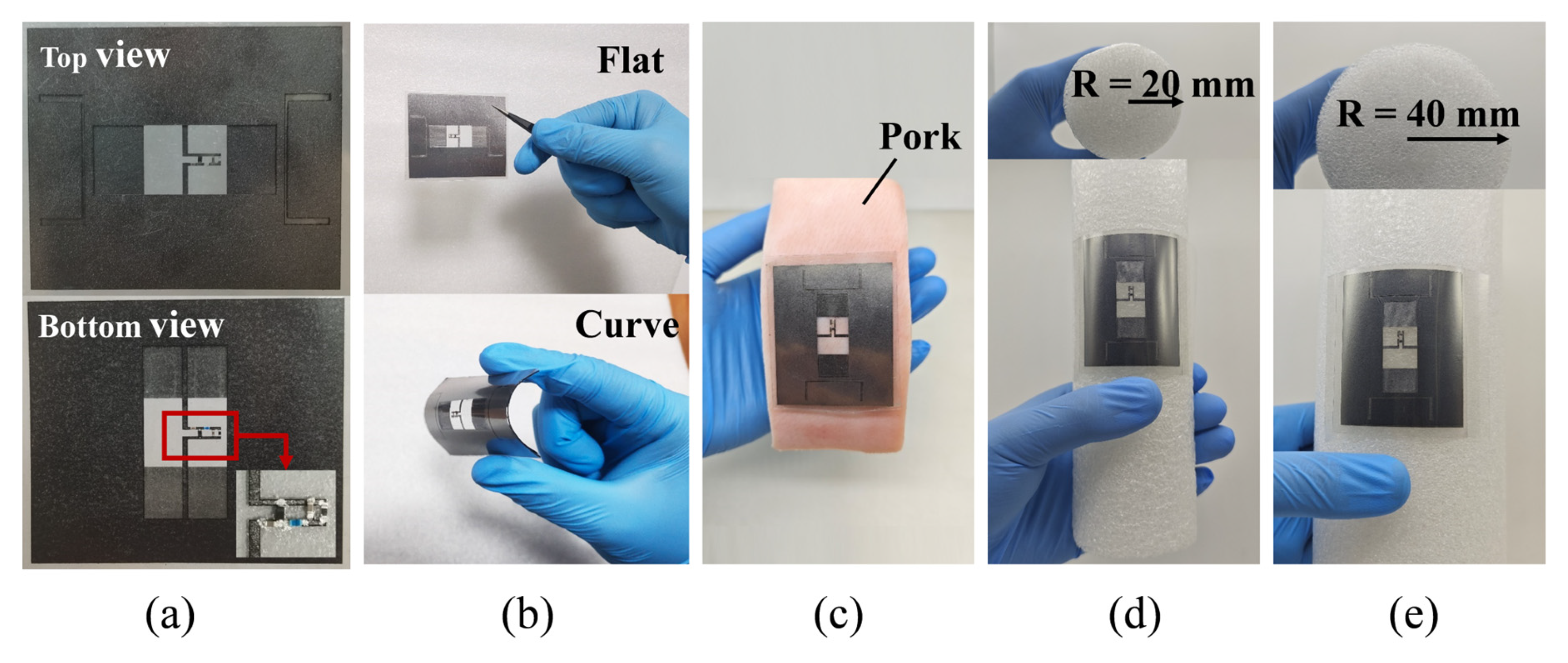
4.2. Fabrication Prototype and Measured Results

As shown in Figure 19, the first step involves cutting the CGF materials into the required patterns using the LPKF Protolaser U4 (LPKF Laser & Electronics AG, Garbsen, Germany), a highly accurate laser engraving machine. Then, the layers of the CGF structures are bonded to the Polydimethylsiloxane (PDMS) substrate. Finally, the lumped components are soldered using a conductive adhesive (silver colloidal suspension 05001-AB), which has a typical sheet resistivity of 12 mΩ/square. The rectenna is fabricated and tested, as shown in Figure 20a. Two states of rectenna have been indicated in Figure 20b. The flat situation corresponds to Case 1, and the curved state indicates that the rectenna can be bent easily. To simulate the human body and verify the performance in a real-world scenario, a slice of pork was used as a substitute for the human body, as shown in Figure 20c. This was carried out to test the performance of the rectenna in a more accurate environment. Two foams with different curvatures were used to measure the rectenna’s performance under various operating conditions, as shown in Figure 20d,e.
The rectenna was tested in an anechoic chamber, as shown in Figure 21. As shown in Figure 21a, a signal generator was connected with a 40 dB gain power amplifier (PA) as the RF source. A spectrum analyzer was used to calibrate the input power and a standard horn antenna was used to transmit the RF power. The rectenna was located 1 m away from the horn antenna within the far-field region. A multimeter measured the output DC voltage (V), and the output DC power can be calculated by using P o u t = V 2 R   , where R is the load resistance. The received power P r can be determined using the Friss transmission equation [41]
P r = P i n + G r + G t + L o s s  
where P i n is the power generated by the signal source and amplified by the PA (in dBm), G r is the simulated gain of the receiving antenna (in dBi), G t is the realized gain value of the transmitting horn antenna (in dBi), and L o s s is the transmission loss (in dB). The L o s s can be calculated with the equation [42]
L o s s = 20 log 10 λ 4 π r
where λ is the wavelength, and r is the distance between the horn antenna (1 m). The conversion efficiency of the rectenna was then calculated by P o u t P r .
Figure 22 presents the measured and simulated conversion efficiency of the rectenna as a function of frequency at different input power levels. The simulated and measured results show good agreement. The measured peak conversion efficiencies were 49.2%, 27.9%, and 15.3% at the 3.5 GHz band and 40.6%, 21.6%, and 10.4% at the 4.9 GHz band, corresponding to input power levels of 0 dBm, −10 dBm, and −15 dBm, respectively. Notably, the conversion efficiency of the proposed rectenna remains above 10% even at an input power of −15 dBm, demonstrating its suitability for low-input-power applications.
Furthermore, the proposed rectenna was measured under different operational conditions to evaluate its practical performance in wearable applications. As shown in Figure 20b–e, the scenarios include Case 1 (rectenna on a flat surface), Case 2 (rectenna on pork), Case 3 (rectenna bent with a 20 mm radius), and Case 4 (rectenna bent with a 40 mm radius). Figure 23 shows the conversion efficiencies as a function of frequency for each operational condition at 0 dBm. The rectenna achieves peak conversion efficiency at 3.47 and 4.86 GHz, 3.46 and 4.85 GHz, 3.45 and 4.9 GHz, and 3.46 and 4.87 GHz for Cases 1, 2, 3, and 4, respectively. Although the operational conditions affect the highest conversion efficiencies, the rectenna consistently reaches an overall conversion efficiency of 40% at the operating bands. In addition, the measured results align well with the simulated results, and the slight differences may be caused by fabrication errors and the parasitic effects of the solder joints. The agreement between the measured and simulated results confirms the rectenna’s robust performance in various conditions, which is critical for its use in wearable applications.
Figure 24 presents the measured and simulated output DC voltage and conversion efficiency at the 3.5 GHz band and 4.9 GHz. It is obtained that starting from an input power level of −15 dBm, both the output voltage and conversion efficiency increase rapidly and then level off. The average measured peak conversion efficiency is 50.5% and 43.4%, with corresponding output voltages of 667 mV and 621 mV for the two operating bands when the rectenna is placed in different test scenarios. Compared with the simulated conversion efficiency, the decrease in efficiency is attributed to the impedance mismatch. The fabricated antenna impedance changes slightly due to the deviation of the actual component values from their ADS models and manufacturing tolerances.
To evaluate the rectenna’s performance in real-world conditions, we measured the output voltage in an indoor environment over a two-hour period using a digital multimeter (OWON B35+). The input power levels fluctuate due to the movement of persons and multipath effects indoors from the RF source, replicating real-world conditions. Figure 25a shows that the ambient power density was approximately 1.87 µW/m2. The rectenna’s output voltage was continuously monitored in real time, and the results (see Figure 25b) showed that while minor fluctuations were observed, the voltage remained generally stable, averaging about 53.2 mV with a peak of 65.9 mV. The results indicate that the proposed rectenna reliably harvests energy for continuous use in dynamic environments, giving it potential for powering wearable electronics like health monitors, fitness trackers, or wearable sensors.
Table 5 compares the performance of the proposed rectenna with that of several previously reported designs. The proposed rectenna offers significant advancements for wearable applications. Since wearable rectennas are typically deployed on the human body, achieving high body isolation is critical. In contrast to omnidirectional designs, our rectenna exhibits a highly directional radiation pattern, enhancing body isolation compared to existing works [19,24,25]. In addition, our design features a compact structure that supports dual-band operation, outperforming previous designs in terms of size and frequency versatility [15,28,30]. In addition, the proposed rectenna demonstrates a competitive conversion efficiency compared to other designs. Moreover, by utilizing graphene-based films, our rectenna offers superior corrosion resistance, crucial for devices exposed to humidity and skin contact. These advantages make it a promising candidate for wearable applications.

5. Conclusions

In this study, a novel dual-band electromagnetic dipole rectenna based on high CGFs was proposed and experimentally validated. The rectenna integrates a dual-band antenna with a rectifier optimized for efficient energy harvesting in the 3.5 and 4.9 GHz bands. The design ensures high conversion efficiency and excellent directional radiation performance under various conditions, including flat, human body, and bending scenarios, by careful impedance matching between the antenna and rectifier. The rectenna demonstrates a maximum conversion efficiency of 53.43% and 43.95% at two operating bands with an input power of 4 dBm, highlighting its exceptional energy-harvesting capabilities. Its compact, low-profile design, combined with the use of flexible CGF and PDMS materials, ensures excellent mechanical flexibility and conformability, making it highly suitable for wearable applications. Compared to conventional metallic rectennas, the proposed rectenna offers significant advantages in terms of flexibility, multiband operation, and integration potential. The proposed rectenna can be further explored to integrate energy storage systems, addressing the growing demands for energy-harvesting applications in wearable electronics.

Author Contributions

J.Z.: conceptualization, supervision and project administration, writing and editing; X.S.: investigation and design, data analysis and writing and editing; W.W.: review and editing; D.H.: methodology and project administration. All authors have read and agreed to the published version of the manuscript.

Funding

This research was funded by the National Natural Science Foundation of China, Grant number 62001338, and the Fundamental Research Funds for the Central Universities, Grant number 104972024KFYjc0064.

Data Availability Statement

Data are contained within the article. The original contributions presented in this study are included in the article. Further inquiries can be directed to the corresponding author.

Conflicts of Interest

The authors declare no conflicts of interest.

References

  1. Costanzo, A.; Masotti, D. Energizing 5G: Near- and Far-Field Wireless Energy and Data Trantransfer as an Enabling Technology for the 5G IoT. IEEE Microw. Mag. 2017, 18, 125–136. [Google Scholar]
  2. Niu, S.; Matsuhisa, N.; Beker, L.; Li, J.; Wang, S.; Wang, J.; Jiang, Y.; Yan, X.; Yun, Y.; Burnett, W.; et al. A wireless body area sensor network based on stretchable passive tags. Nat. Electron. 2019, 2, 361–368. [Google Scholar]
  3. Rosso, M. Intentional and Inherent Nonlinearities in Piezoelectric Energy Harvesting; Springer Nature: Cham, Switzerland, 2024. [Google Scholar]
  4. Song, K.; Bonnin, M.; Traversa, F.L.; Bonani, F. Broadband vibration energy harvesting using nonlinear multi degree-of-freedom mechanical filters. In Nonlinear Dynamics; Springer: Berlin/Heidelberg, Germany, 2025. [Google Scholar]
  5. Wagih, M.; Balocchi, L.; Benassi, F.; Carvalho, N.B.; Chiao, J.; Correia, R.; Costanzo, A.; Cui, Y.; Georgiadou, D.; Gouveia, C.; et al. Microwave-Enabled Wearables: Underpinning Technologies, Integration Platforms, and Next-Generation Roadmap. IEEE J. Microw. 2023, 3, 193–226. [Google Scholar]
  6. Ullah, M.A.; Keshavarz, R.; Abolhasan, M.; Lipman, J.; Esselle, K.P.; Shariati, N. A Review on Antenna Technologies for Ambient RF Energy Harvesting and Wireless Power Transfer: Designs, Challenges and Applications. IEEE Access 2022, 10, 17231–17267. [Google Scholar]
  7. Muhammad, S.; Tiang, J.J.; Wong, S.K.; Rambe, A.H.; Adam, I.; Smida, A.; Waly, M.I.; Iqbal, A.; Abubakar, A.S.; Mohd Yasin, M.N. Harvesting Systems for RF Energy: Trends, Challenges, Techniques, and Tradeoffs. Electronics 2022, 11, 959. [Google Scholar]
  8. Liao, L.; Li, Z.; Tang, Y.; Chen, X. Dual-Polarized Stacked Patch Antenna for Wireless Communication Application and Microwave Power Transfer. Electronics 2021, 10, 2988. [Google Scholar]
  9. Nusrat, T.; Roy, S.; Lotfi-Neyestanak, A.A.; Noghanian, S. Far-Field Wireless Power Transfer for the Internet of Things. Electronics 2023, 12, 207. [Google Scholar]
  10. Fernandez-Munoz, M.; Missous, M.; Sadeghi, M.; Lopez-Espi, P.L.; Sanchez-Montero, R.; Martinez-Rojas, J.A.; Diez-Jimenez, E. Fully Integrated Miniaturized Wireless Power Transfer Rectenna for Medical Applications Tested inside Biological Tissues. Electronics 2024, 13, 3159. [Google Scholar]
  11. Jing, J.; Yang, B.; Yan, L.; Shinohara, N.; Liu, C. Fully Polarized Wideband Omnidirectional RF Harvester with Highly Efficient DC Power Combination. Electronics 2024, 13, 4891. [Google Scholar]
  12. Deng, X.; Yang, P.; Chen, S.; Ren, W. Design of a 2.4 & 5.8 GHz Efficient Circularly Polarized Rectenna for Wireless Power Transfer Applications. Electronics 2023, 12, 2645. [Google Scholar]
  13. Yu, B.; Wang, Z.; Ju, L.; Zhang, C.; Liu, Z.; Tao, L.; Lu, W. Flexible and Wearable Hybrid RF and Solar Energy Harvesting System. IEEE Trans. Antennas Propag. 2022, 70, 2223–2233. [Google Scholar]
  14. Zhang, J.; Wang, Y.; Song, R.; Kou, Z.; He, D. Highly Flexible Graphene-Film-Based Rectenna for Wireless Energy Harvesting. Energy Environ. Mater. 2024, 7, e12548. [Google Scholar]
  15. Chen, Z.; Song, C.; Zhang, J.; Zheng, X.; Volskiy, V.; Chu, P.; Vandenbosch, G.A.E. Wearable Rectenna With Integrated Miniaturized Feeding Slot and Rectifier Structure. IEEE Trans. Antennas Propag. 2023, 71, 3868–3881. [Google Scholar]
  16. Fernández, M.; Vázquez, C.; Ver Hoeye, S. 2.4 GHz Fully Woven Textile-Integrated Circularly Polarized Rectenna for Wireless Power Transfer Applications. IEEE Access 2024, 12, 89836–89844. [Google Scholar]
  17. Lopez-Garde, J.; Del-Rio-Ruiz, R.; Legarda, J.; Rogier, H. 2 × 2 Textile Rectenna Array with Electromagnetically Coupled Microstrip Patch Antennas in the 2.4 GHz WiFi Band. Electronics 2021, 10, 1447. [Google Scholar]
  18. Patil, D.D.; Subramanian, K.S.; Pradhan, N.C. 3-D-Printed Dual-Band Rectenna System for Green IoT Application. IEEE Trans. Circuits Syst. II Express Briefs 2023, 70, 2864–2868. [Google Scholar] [CrossRef]
  19. Sang, J.; Qian, L.; Wang, X.; Shi, G. A dual-band omnidirectional rectenna for radio-frequency energy harvesting applications. Microelectron. J. 2025, 156, 106533. [Google Scholar] [CrossRef]
  20. Erman, F.; Koziel, S.; Zyoud, A.; Leifsson, L.; Ullah, U.; Alkaraki, S. Power Transmission for Millimeter-Wave Indoor/Outdoor Wearable IoT Devices Using Grounded Coplanar Waveguide-Fed On-Body Antenna. IEEE Access 2025, 13, 14063–14072. [Google Scholar] [CrossRef]
  21. Wagih, M.; Weddell, A.S.; Beeby, S. Omnidirectional Dual-Polarized Low-Profile Textile Rectenna with Over 50% Efficiency for Sub-μ W/cm2 Wearable Power Harvesting. IEEE Trans. Antennas Propag. 2021, 69, 2522–2536. [Google Scholar]
  22. Wagih, M.; Komolafe, A.; Weddell, A.S.; Beeby, S. Broadband Compact Substrate-Independent Textile Wearable Antenna for Simultaneous Near- and Far-Field Wireless Power Transmission. IEEE Open J. Antennas Propag. 2022, 3, 398–411. [Google Scholar]
  23. Eid, A.; Hester, J.G.D.; Costantine, J.; Tawk, Y.; Ramadan, A.H.; Tentzeris, M.M. A Compact Source–Load Agnostic Flexible Rectenna Topology for IoT Devices. IEEE Trans. Antennas Propag. 2020, 68, 2621–2629. [Google Scholar]
  24. Du, C.; Cheng, F.; Yang, Y.; Zhu, H.; Gu, C. Omnidirectional Flexible Tri-Band Rectenna with Eliminated Matching Circuit for Ambient RF Energy Harvesting. IEEE Trans. Microw. Theory Tech. 2025, 73, 674–686. [Google Scholar]
  25. Wang, C.; Zhang, J.; Bai, S.; Chang, D.; Duan, L. A Multiband Compact Flexible Energy Collector for Wearable or Portable IoT Devices. IEEE Antennas Wirel. Propag. Lett. 2023, 22, 1164–1168. [Google Scholar]
  26. Ha, T.D.; Nie, X.; Akinsolu, M.; Liu, B.; Chen, P. An Artificial-Intelligence-Assisted Optimization of Imperceptible Multimode Rectenna. IEEE Antennas Wirel. Propag. Lett. 2024, 23, 3559–3563. [Google Scholar] [CrossRef]
  27. Wagih, M.; Hilton, G.S.; Weddell, A.S.; Beeby, S. Broadband Millimeter-Wave Textile-Based Flexible Rectenna for Wearable Energy Harvesting. IEEE Trans. Microw. Theory Tech. 2020, 68, 4960–4972. [Google Scholar]
  28. Adami, S.; Proynov, P.; Hilton, G.S.; Yang, G.; Zhang, C.; Zhu, D.; Li, Y.; Beeby, S.P.; Craddock, I.J.; Stark, B.H. A Flexible 2.45-GHz Power Harvesting Wristband with Net System Output From −24.3 dBm of RF Power. IEEE Trans. Microw. Theory Tech. 2018, 66, 380–395. [Google Scholar]
  29. Yahya Alkhalaf, H.; Ahmad, M.Y.; Ramiah, H.; Zakir Hossain, A.K.M.; Kayser Azam, S.M.; Thiha, A. Flexible Meta-Patch Rectenna Array for Energizing Low-Power Wearable Medical Sensors. IEEE Access 2024, 12, 121570–121585. [Google Scholar]
  30. Sanusi, O.M.; Ghaffar, F.A.; Shamim, A.; Vaseem, M.; Wang, Y.; Roy, L. Development of a 2.45 GHz Antenna for Flexible Compact Radiation Dosimeter Tags. IEEE Trans. Antennas Propag. 2019, 67, 5063–5072. [Google Scholar]
  31. Battistini, G.; Paolini, G.; Costanzo, A.; Masotti, D. A Novel 3-D Printed Dual-Port Rectenna for Simultaneous Energy Harvesting and Backscattering of a Passively Generated UWB Pulse. IEEE Trans. Microw. Theory Tech. 2024, 72, 812–821. [Google Scholar] [CrossRef]
  32. Shah, I.A.; Zada, M.; Shah, S.A.A.; Basir, A.; Yoo, H. Flexible Metasurface-Coupled Efficient Wireless Power Transfer System for Implantable Devices. IEEE Trans. Microw. Theory Tech. 2024, 72, 2534–2547. [Google Scholar] [CrossRef]
  33. Lin, W.; Ziolkowski, R.W. Electrically Small, Single-Substrate Huygens Dipole Rectenna for Ultracompact Wireless Power Transfer Applications. IEEE Trans. Antennas Propag. 2021, 69, 1130–1134. [Google Scholar]
  34. Tang, D.; Wang, Q.; Wang, Z.; Liu, Q.; Zhang, B.; He, D.; Wu, Z.; Mu, S. Highly sensitive wearable sensor based on a flexible multilayer graphene film antenna. Sci. Bull. 2018, 63, 574–579. [Google Scholar]
  35. Song, R.; Zhao, X.; Wang, Z.; Fu, H.; Han, K.; Qian, W.; Wang, S.; Shen, J.; Mao, B.; He, D. Sandwiched Graphene Clad Laminate: A Binder-Free Flexible Printed Circuit Board for 5G Antenna Application. Adv. Eng. Mater. 2020, 22, 2000451. [Google Scholar]
  36. Song, R.; Mao, B.; Wang, Z.; Hui, Y.; Zhang, N.; Fang, R.; Zhang, J.; Wu, Y.; Ge, Q.; Novoselov, K.S.; et al. Comparison of copper and graphene-assembled films in 5G wireless communication and THz electromagnetic-interference shielding. Proc. Natl. Acad. Sci. USA 2023, 120, e2209807120. [Google Scholar] [CrossRef]
  37. Xu, R.; Shen, Z. Wearable Ungrounded Tag Antenna for UHF RFID Applications. IEEE Trans. Antennas Propag. 2023, 71, 3665–3670. [Google Scholar]
  38. Marrocco, G. RFID Antennas for the UHF Remote Monitoring of Human Subjects. IEEE Trans. Antennas Propag. 2007, 55, 1862–1870. [Google Scholar]
  39. Vital, D.; Bhardwaj, S.; Volakis, J.L. Textile-Based Large Area RF-Power Harvesting System for Wearable Applications. IEEE Trans. Antennas Propag. 2020, 68, 2323–2331. [Google Scholar] [CrossRef]
  40. Stuchly, M.A.; Stuchly, S.S. Dielectric properties of biological substances-tabulated. J. Microw. Power 1980, 15, 19–26. [Google Scholar]
  41. Song, C.; Huang, Y.; Zhou, J.; Carter, P.; Yuan, S.; Xu, Q.; Fei, Z. Matching Network Elimination in Broadband Rectennas for High-Efficiency Wireless Power Transfer and Energy Harvesting. IEEE Trans. Ind. Electron. 2017, 64, 3950–3961. [Google Scholar]
  42. Huang, Y.; Boyle, K. Antennas: From Theory to Practice; John Wiley & Sons: Chichester, UK, 2008. [Google Scholar]
Figure 1. (a) Cross-sectional image of the CGF; (b) photograph of the CGF.
Electronics 14 01314 g001
Figure 2. Geometry of the proposed antenna: (a) top view, (b) bottom view, (c) side view.
Electronics 14 01314 g002
Figure 3. The design concept of the electromagnetic dipoles radiates a unidirectional pattern.
Electronics 14 01314 g003
Figure 4. Surface current distributions of the proposed antenna: (a) amplitude at 3.5 GHz; (b) vector map at 3.5 GHz; (c) amplitude at 4.9 GHz; (d) vector map at 4.9 GHz.
Electronics 14 01314 g004
Figure 5. Design and optimization process of the proposed antenna.
Electronics 14 01314 g005
Figure 6. Simulated results in Step 1 at 3.5 GHz: (a) surface current vector map; (b) radiation pattern.
Electronics 14 01314 g006
Figure 7. Simulated results in Step 2. (a) Bottom surface current vector map at 3.5 GHz. (b) Top surface current vector map at 3.5 GHz. (c) Radiation pattern at 3.5 GHz. (d) Bottom surface current vector map at 4.9 GHz. (e) Top surface current vector map at 4.9 GHz. (f) Radiation pattern at 4.9 GHz.
Electronics 14 01314 g007
Figure 8. Simulated results in Step 3. (a) Bottom surface current vector map at 3.5 GHz. (b) Top surface current vector map at 3.5 GHz. (c) Radiation pattern at 3.5 GHz. (d) Bottom surface current vector map at 4.9 GHz. (e) Top surface current vector map at 4.9 GHz. (f) Radiation pattern at 4.9 GHz.
Electronics 14 01314 g008
Figure 9. Effects of changing the critical parameters, (a) W2, (b) L2, (c) W4, and (d) S5, on the antenna front-to-back ratio.
Electronics 14 01314 g009
Figure 10. The possible operating cases of the antenna. (a) On a flat surface. (b) On the human body. (c) Bending with a curvature of 20 mm. (d) Bending with a curvature of 40 mm.
Electronics 14 01314 g010
Figure 11. The impedance of the proposed antenna under different operation cases.
Electronics 14 01314 g011
Figure 12. The normalized radiation pattern under different operation cases: (a) Case 1, (b) Case 2, (c) Case 3, (d) Case 4.
Electronics 14 01314 g012
Figure 13. The simulated FBR of the antenna across the two operational frequency bands under varying curvature conditions.
Electronics 14 01314 g013
Figure 14. Simulated specific absorption rate of the wearable antenna on the human body: (a) normalized to 1 g tissue mass at 3.5 GHz; (b) normalized to 10 g tissue mass at 3.5 GHz; (c) normalized to 1 g tissue mass at 4.9 GHz; (d) normalized to 10 g tissue mass at 4.9 GHz.
Electronics 14 01314 g014aElectronics 14 01314 g014b
Figure 15. Layout and schematic of the rectifier: (a) system configuration with the circuit dimensions in mm; (b) rectifier equivalent circuit.
Electronics 14 01314 g015
Figure 16. The simulated conversion efficiency as a function of R values.
Electronics 14 01314 g016
Figure 17. The simulated efficiency and S11 of the rectifier with various L.
Electronics 14 01314 g017
Figure 18. Simulated S11 of the rectifier as a function of frequency for different cases (Case 1: on a flat surface; Case 3: on the body; Case 3: on foam with a curvature of 20 mm; Case 4: on foam with a curvature of 40 mm).
Electronics 14 01314 g018
Figure 19. The manufacturing process of the rectenna.
Electronics 14 01314 g019
Figure 20. Photographs of the proposed rectenna: (a) fabricated prototype; (b) rectenna on flat and curved surfaces; (c) on pork; (d) on foam with a curvature of 20 mm; (e) on foam with a curvature of 40 mm.
Electronics 14 01314 g020
Figure 21. (a) Measurement setup; (b) the measurement setup in the anechoic chamber.
Electronics 14 01314 g021
Figure 22. The conversion efficiency of the rectenna versus frequency at different captured power levels.
Electronics 14 01314 g022
Figure 23. The conversion efficiencies as a function of the frequency at 0 dBm with different operation cases.
Electronics 14 01314 g023
Figure 24. The output DC voltage values and the conversion efficiency of the rectenna as a function of the input power: (a) at 3.5 GHz; (b) at 4.9 GHz.
Electronics 14 01314 g024
Figure 25. (a) Measurement setup; (b) measured output voltage of the proposed rectenna versus time.
Electronics 14 01314 g025
Table 1. Optimized parameters of the proposed antenna (units: mm).
ParameterW1W2W3W4L1L2L3L4
value4712.53123.456331552
ParameterS1S2S3S4S5h
value1.210.51.21.50.5
Table 2. The geometric and electromagnetic properties of different human tissue models.
LayerThickness (Model 1)Thickness (Model 2)Dielectric Const.Electric Cond.Density (Kg/m3)
Skin1 mm5 mm381.46 S/m1100
Fat4.5 mm7 mm5.280.39 S/m1016
Muscle7.5 mm30 mm52.71.88 S/m1006
Table 3. Radiation efficiency of the antenna in different operation conditions.
Frequency BandCase 1 (CGF)Case 1 (Copper)Case 2Case 3Case 4
3.5 GHz48.2%67.8%46.6%49.9%49.1%
4.9 GHz56.2%73.7%52.4%49.6%50.9%
Table 4. Components used in the design.
L2.7 nH, LQW15AN2N7D0Z, chip inductor
C1390 pF, GRM1555C1E391JA01, chip capacitor
C2470 pF, GRM1555C1E471JA01, chip capacitor
DiodeSMS7630, Schottky diode
Table 5. Comparison of the proposed rectenna and other related flexible designs.
Ref.Frequency BandNumber of
Substrate Layer
Radiation
Pattern
Size in λ0Corrosion ResistancePeak Conversion Efficiency (%)
[15]SingleTwoDirectional0.75 × 0.75no56 @ −5dBm
[19]TwoOneOmnidirectional0.29 × 0.61no40 @ 1 dBm/37 @ 0 dBm
[24]ThreeOneOmnidirectional0.34 × 0.07no70 @ 1 dBm/59 @ 3 dBm
/50 @ 4 dBm
[25]FourOneOmnidirectional0.25 × 0.31no48 @ 5 dBm/50 @ 5 dBm
/42 @ 10 dBm/34 @ 10 dBm
[28]SingleTwoDirectional0.57 × 0.52no56 @ −5 dBm
[30]SingleTwoDirectional0.82 × 0.16no49 @ 20 dBm
This workTwoOneDirectional0.65 × 0.54yes53 @ 4 dBm/47 @ 4 dBm
λ0: Free-space wavelength at the center frequency.
Disclaimer/Publisher’s Note: The statements, opinions and data contained in all publications are solely those of the individual author(s) and contributor(s) and not of MDPI and/or the editor(s). MDPI and/or the editor(s) disclaim responsibility for any injury to people or property resulting from any ideas, methods, instructions or products referred to in the content.

