1. Introduction
Beam-scanning dual-polarized antennas have been adopted in wireless communication systems due to their ability to enhance signal coverage, suppress interference, and increase network capacity. By adjusting the main beam pointing and null directions, they can meet the demands for antennas in complex and changeable environments [
1]. Dual-polarized beam-scanning antennas with low cross-polarization, compact size, low cost, fast response, and wide coverage are always desired in some applications such as indoor communication systems.
At present, electronic pattern-reconfigurable techniques are applied in beam-scanning antenna designs. An antenna with PIN-loaded active parasitic elements, including patch antenna [
2,
3], dipole antenna [
4,
5], and monopole antenna [
6], is one of the most popular ways to design pattern-reconfigurable antennas. Based on the principle of the Yagi–Uda antenna, the active parasitic element can function as either a reflector or a director by altering the states of the PIN diodes integrated into it. Consequently, the beam direction will be steered toward the directors and away from the reflectors. Two-dimensional beam-scanning antennas are investigated to further enhance the coverage. In [
7], a pattern-reconfigurable patch antenna with active parasitic complementary split-ring resonators (CSRRs) is proposed. In [
8], 2D beam switching is realized based on PIN diodes loaded in a ring-shaped pixel structure. Although this method is straightforward and only a few PIN diodes are required, it limits the number of available beam states. If the beams are not arranged densely, the gain between adjacent patterns diminishes, potentially leading to a decline in communication performance at those angles. A prototype that can provide dense beams is reported in [
9] by individually controlling the states of 20 PIN diodes, but the bias circuit is complex. A dual-polarized pattern-reconfigurable cross-dipole antenna is proposed in [
10], by utilizing varactors instead of PIN diodes. Its beam can continuously steer in the E-plane for either port.
The electromagnetic metasurface, including the reflective or the transmissive surface, can achieve beam scanning by phase modulation [
11,
12,
13]. By using an active reflective metasurface, a continuous beam-scanning antenna is proposed in [
12]. A dual-polarized cross-dipole antenna, acting as a source antenna, is used to illuminate the reflective metasurface. The beam-steering range is only ±20° due to the low illumination efficiency of the reflective metasurface. The integration of a large number of active components on a thick laminate with high dielectric constants will significantly increase fabrication costs, power consumption, and assembly complexity. A dual-polarized beam-scanning antenna based on a dual-layer transmissive surface is proposed in [
13], but the high profile and small beam-scanning range in its E-plane cannot meet the demands of current communication systems.
In this paper, a dual-polarized 2D beam-scanning antenna is proposed in the frequency range of 3.4–3.6 GHz. The proposed antenna is composed of a stacked patch antenna and four parasitic double-square-loop elements. By tuning the capacitances of cost-effective varactors, SMV1430, embedded on the parasitic elements, the antenna beam can be continuously scanned for both polarizations in two principal planes. The measured results show that the antenna has a good impedance match from 3.4 GHz to 3.6 GHz and good beam-scanning performance at two planes within the ranges of ±32°.
2. Antenna Structure and Working
The configuration of the proposed dual-polarized 2D beam-scanning antenna is illustrated in
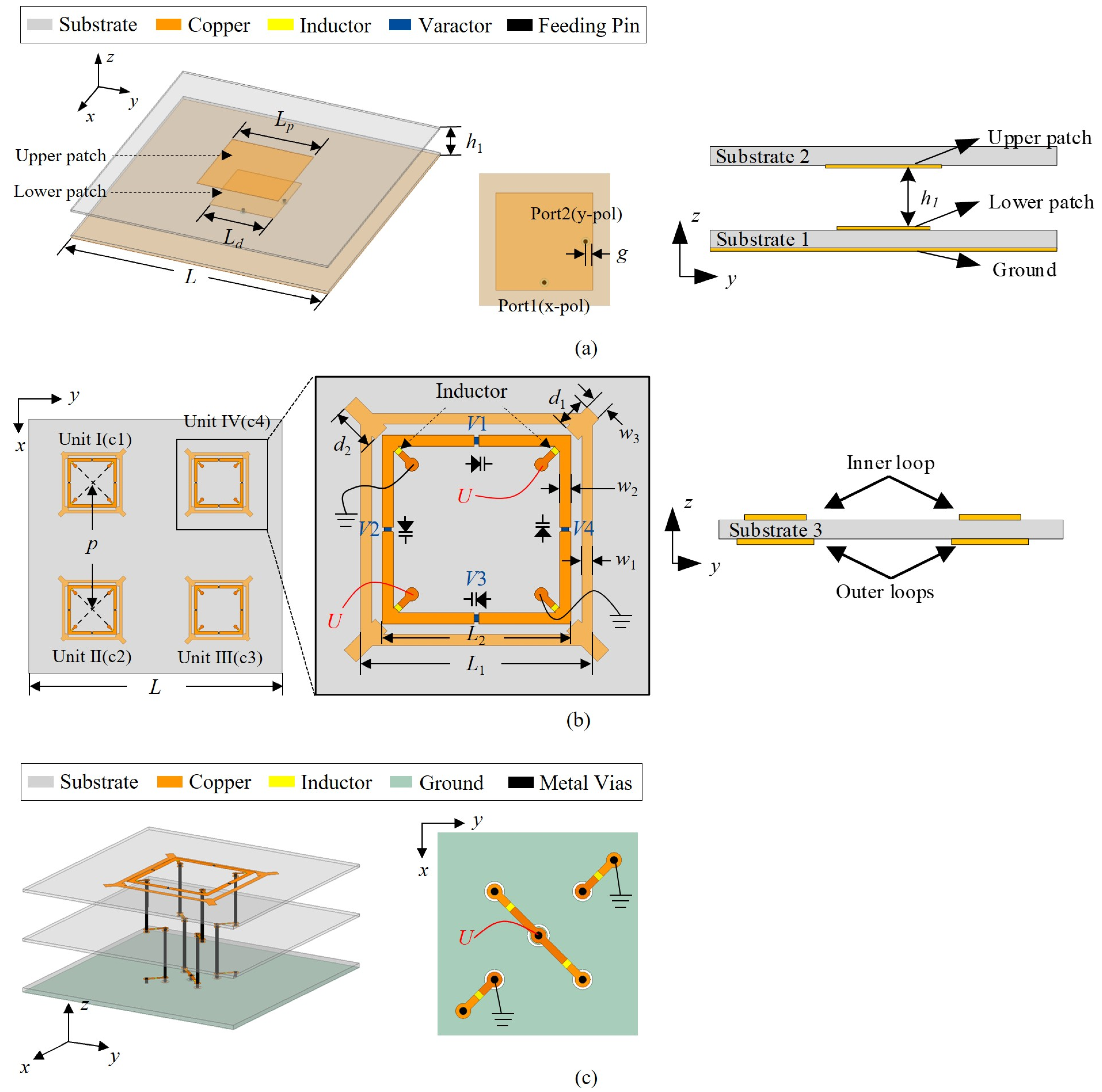
Figure 1. The antenna is printed on three Rogers RO4003 laminates, named substrate 1, substrate 2, and substrate 3, with dielectric constants of 3.55. The thicknesses of those substrates are 0.813 mm, 0.508 mm, and 0.508 mm, respectively. The proposed antenna has a dual-polarized driven antenna, a beam-steering layer, and biasing structures. The detailed structures are plotted in
Figure 2. And the detailed dimensions of the proposed antenna are listed in
Table 1.
As shown in
Figure 2a, the dual-polarized patch antenna is a probe-fed dual-polarized stacked patch antenna. A square upper patch with a size of
Lp ×
Lp is printed on the bottom side of substrate 2, and a square lower patch with a size of
Ld ×
Ld is printed on the top side of substrate 2. There is an air gap with a thickness of
h1 between the two patches. The antenna has two ports. Port 1 is x-polarized, and Port 2 is y-polarized. The stacked square patches are used to improve the impedance match.
As depicted in
Figure 2b, the beam-steering layer comprises four RDSLs, specifically named Unit I to IV. Each RDSL consists of two concentric square loops. The outer loops are printed on the bottom side of substrate 3, while the inner loops are on the top side of substrate. Four additional open-circuit stubs are placed on the corners of each outer loop to fine tune the resonant frequency of the outer loops, without changing the distance between the outer and inner loops. Four cost-efficient Skyworks SMV1430 varactor diodes are integrated into the inner square loop. The varactor can be modeled as a series circuit consisting of a 3 Ω resistor, a 0.45 nH inductor, and a tunable capacitor. As the voltage applied from the cathode to the anode of the varactor increases from 0 V to 30 V, the capacitance of this tunable capacitor changes from 1.24 pF to 0.31 pF. The layout of the biasing circuits for varactors is presented in
Figure 2b,c. In each RDSL, vertical metal posts are used to apply a bias voltage to the varactors. Murata LQW15AN27NJ80 RF inductors are utilized to prevent the induced RF current from flowing along the posts while simultaneously providing a pathway for DC biasing voltages. The inductance and self-resonant frequency are 27 nH and 4 GHz. Two vertical metal posts are connected to the ground, and another two are connected to a biasing voltage. The varactors in each RDSL are connected in parallel and only a single voltage is applied on each RDSL.
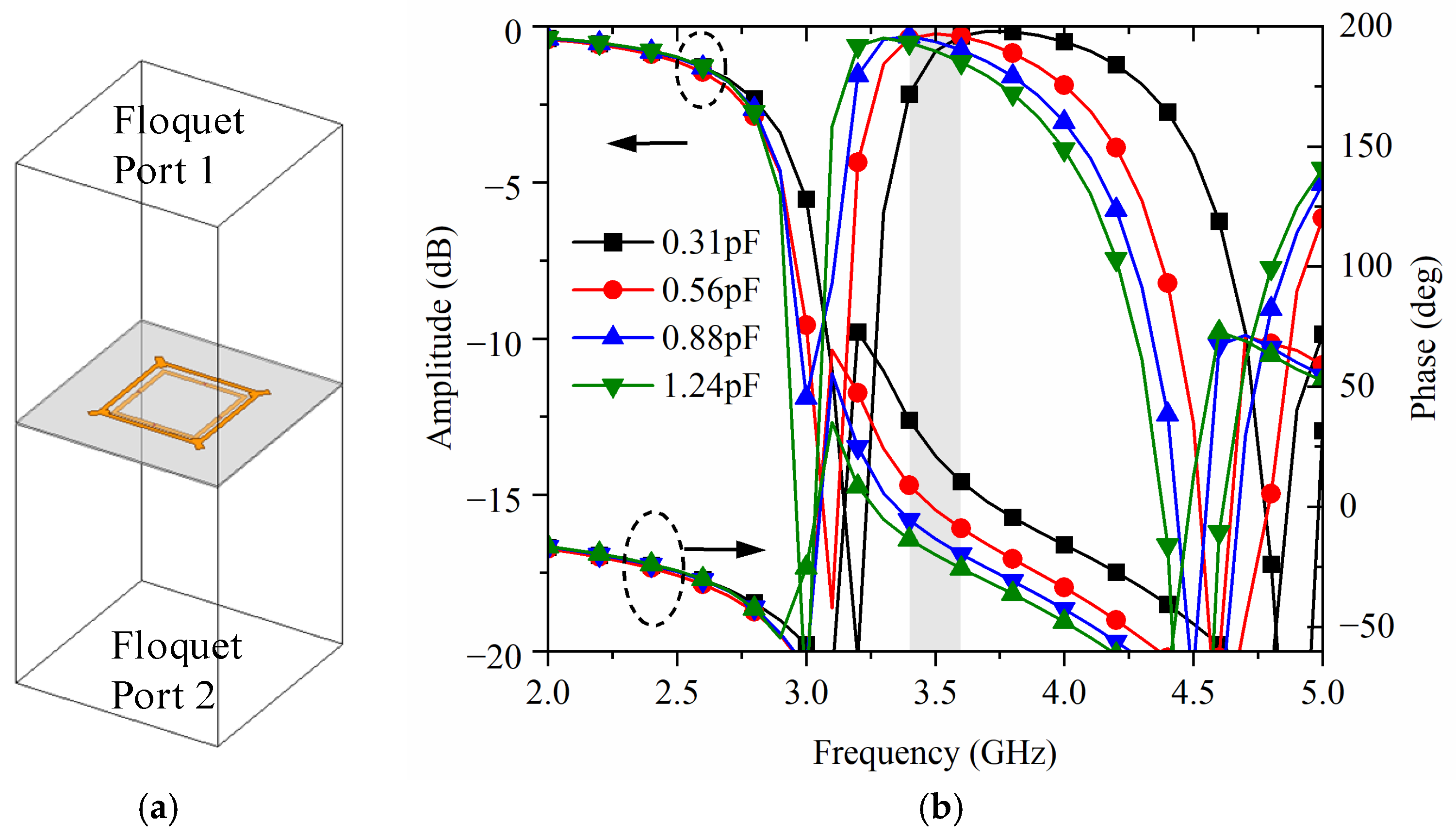
The array of RDSLs is illuminated by the driven antenna, and the EM wave emitted from the driven antenna will pass through the RDSLs. The double-loop structure with varactors produces a desired phase shift within the working band. By individually controlling the RDSLs, the main beam of the antenna can be steered. The transmission amplitude and phase of the RDSL are crucial for beam control. To evaluate the performance of the RDSL, the scattering coefficients of the RDSL with different capacitance values were simulated as shown in
Figure 3. The RDSL was simulated with lattice pair boundaries with a square lattice of 45 mm as shown in
Figure 3a, which is equal to the distance between each RDSL in
Figure 2. The double square loops in each RDSL produced a passband along with two tunable transmission zeros (TZs) around 3 GHz and 4.5 GHz. One TZ was above the passband, while the other was below it. The transmission phase rolled off between the two TZs and nearly spanned a 180° phase range. By increasing the capacitance from 0.31 pF to 1.24 pF, the TZs shifted toward a lower frequency, and the transmission phase decreased at 3.5 GHz. The transmission magnitude was always higher than 2 dB at 3.5 GHz for different capacitance values. The simulated results indicate that, by changing the capacitance of the varactor on RDSL, the transmission phase will change simultaneously. This pronounced phase shift allows the RDSL scatterers to act as spatial phase shifters.
By individually tuning the voltages applied on the RDSLs, the main beam of the antenna can be continuously steered rather than switching between a few states. The radiation patterns of the proposed antenna with different steering angles were simulated as shown in
Figure 4. For each polarization, the scanning ranges were from −31° to 30° in the E-plane and from −34° to 34° in the H-plane. The reason for scanning difference in two planes lies in the fact that the couplings between the patch and RDSLs are not symmetrical in the E-plane and H-plane. The square driven patch works at the TE
10 mode, and the half-power beamwidth (HPBW) in the H-plane is wider than that in the E-plane. This phenomenon will contribute to unequal EM couplings between the patch and the RDSLs. The equivalent capacitances of the varactor on each RDSL at the maximum scanning states and the broadside state are listed in
Table 2.
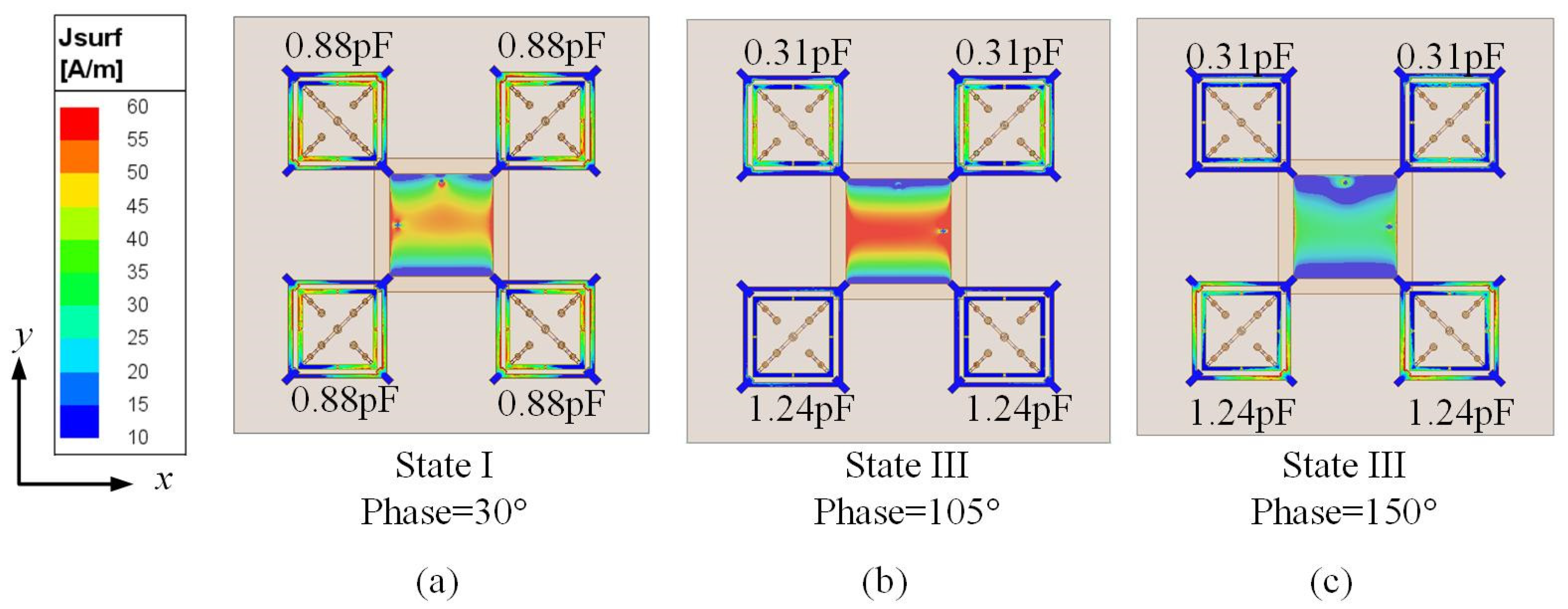
The current distribution of the antenna at different states was also analyzed, and, due to the symmetry of the antenna, only the results of State I and State III with Port 1 excited are presented. At State I, the current distribution is shown in
Figure 5a. The uniform current distribution on four RDSLs leads to a broadside radiation pattern. At State III, the current distributions at two different phases are illustrated in
Figure 5b,c. At a phase of 105°, a strong current flows on unit I and IV, while only a small current can be observed on unit II and III. On the contrary, at a phase of 150°, the current on unit II and III is stronger than that on unit I and IV. The phase difference results in a tiled beam.
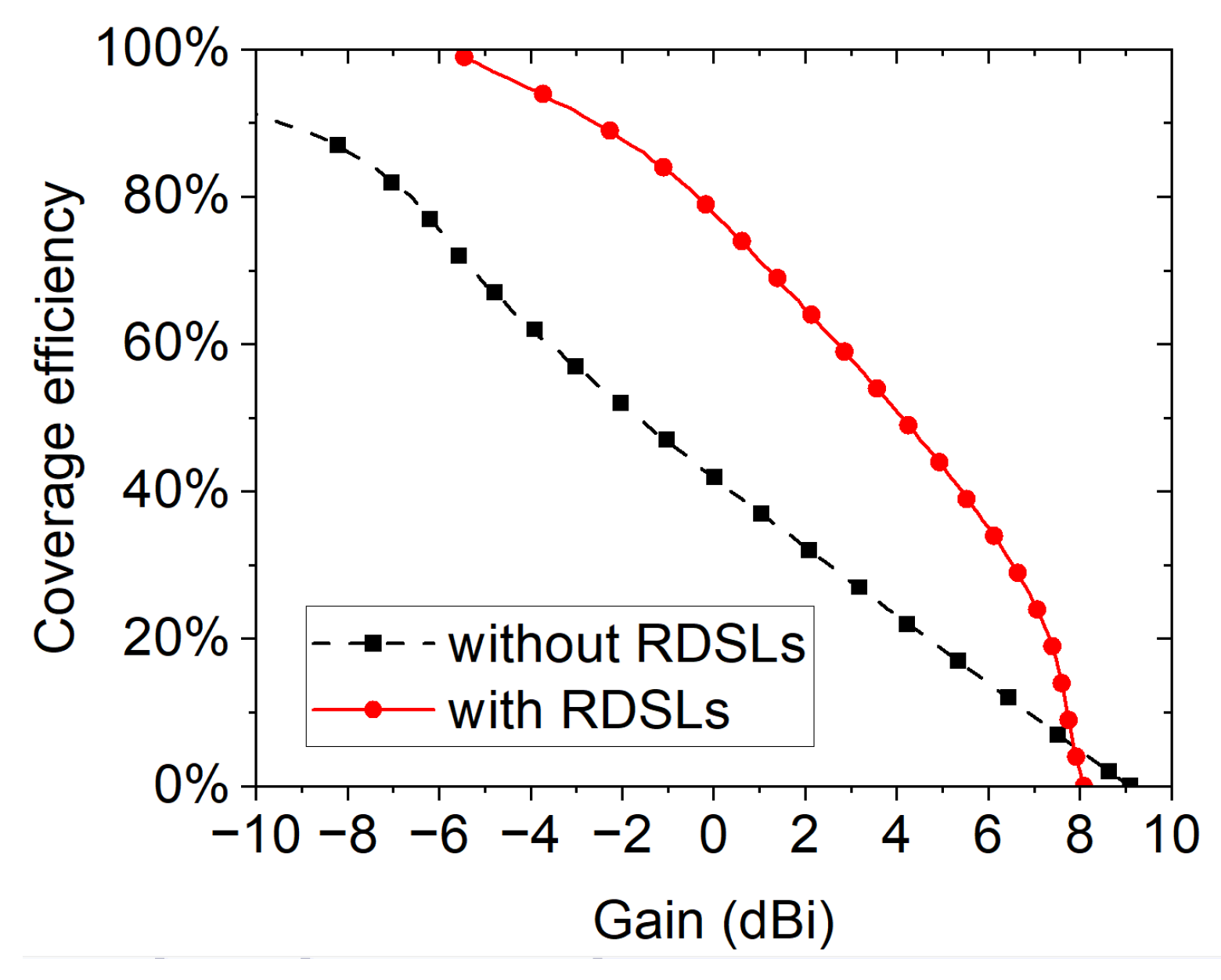
Figure 6 compares the peak gain of the antenna with and without RDSLs in the E-plane and the H-plane. Without RDSLs, the antenna did not have beam-steering capability. The antenna without RDSLs had a directional beam with a half-power beamwidth of 53.0° in the E-plane and 64° in the H-plane. The antenna’s gain rapidly decreased beyond the ±30° angular domain, thus failing to provide good beam coverage. After loading the RDSLs, the gain of the proposed antenna was significantly higher than that of the antenna without RDSLs in most directions. Due to the insertion loss of the beam-steering layer, the radiation efficiency decreased to 83%, and the broadside gain dropped by 1.35 dB, and, within the ±20° angular domain, the gain of the reconfigurable antenna was slightly lower. Although the peak gain of the antenna loaded with RDSLs decreased, the half-power beam coverage in the E-plane and H-plane significantly increased, being 2.2 times and 1.7 times that of the antenna without RDSLs, respectively. The reconfigurable antenna based on the beam-steering layer achieved broader beam coverage and more stable gain. To evaluate the beam-scanning performance, the coverage efficiency
ηc [
14] of the proposed pattern-reconfigurable antenna is plotted in
Figure 7 and is defined as follows [
15]:
where the coverage solid angle is calculated using the total scan pattern higher than a certain gain, and the maximum solid angle is 2π steradians because a hemisphere is chosen. The coverage efficiency of the proposed pattern-reconfigurable antenna for the gain of 4 dBi was better than 50%. The threshold gains for 50% and 80% coverage efficiency were 4 dBi and −0.5 dBi for the proposed antenna, while they were −1.85 dBi and −6.8 dBi for the antenna without beam-steering layers. The coverage efficiency of the proposed antenna significantly improved on adding a beam-steering layer.
3. Simulation and Measurement Results
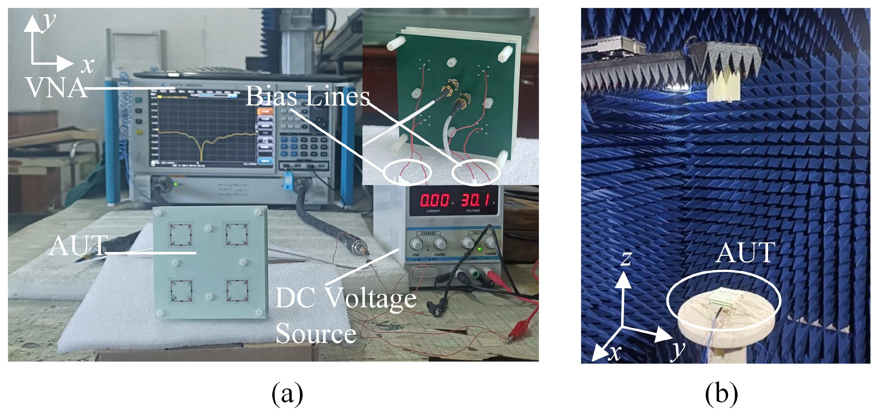
To further validate the proposed design, a prototype was fabricated as shown in
Figure 8. Nylon spacers were used to support the substrate laminates. For the five measured states, varactors were applied with different voltages to provide the desired capacitances.
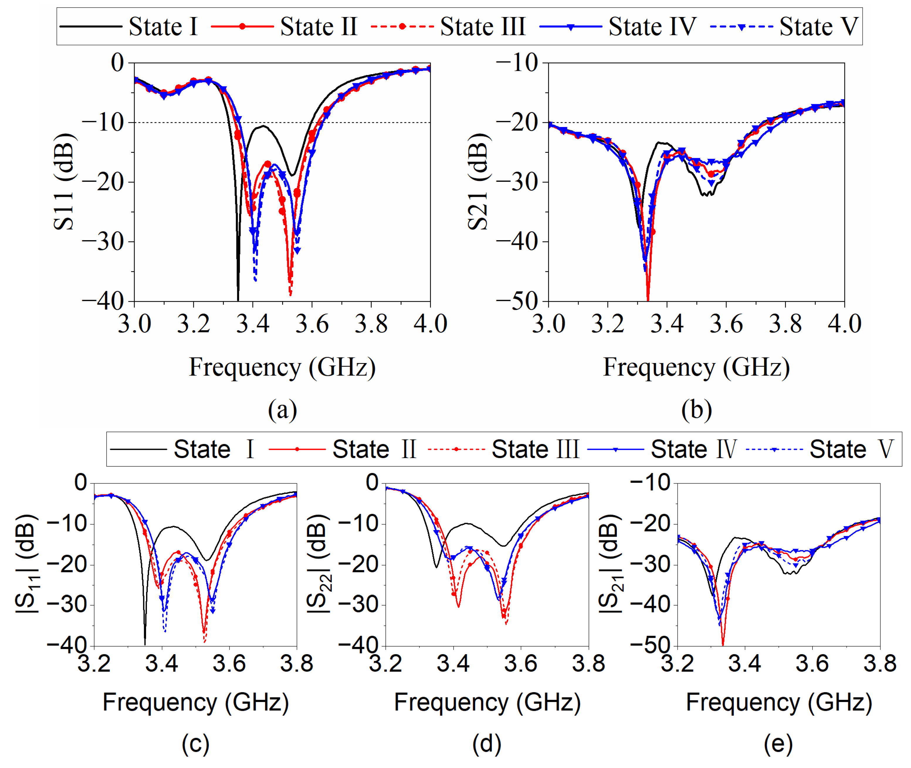
The simulated and measured S-parameters are shown in
Figure 9. The simulated reflection of two polarizations (S11 and S22) overlapped due to the symmetric structure of the antenna. The measured S-parameter agreed well with the simulated results. A little frequency shift was observed. The small deviation may be due to assembly errors. For all the five steering states, the measured reflection coefficients were less than −10 dB. The measured isolations between the two ports were greater than 20 dB.
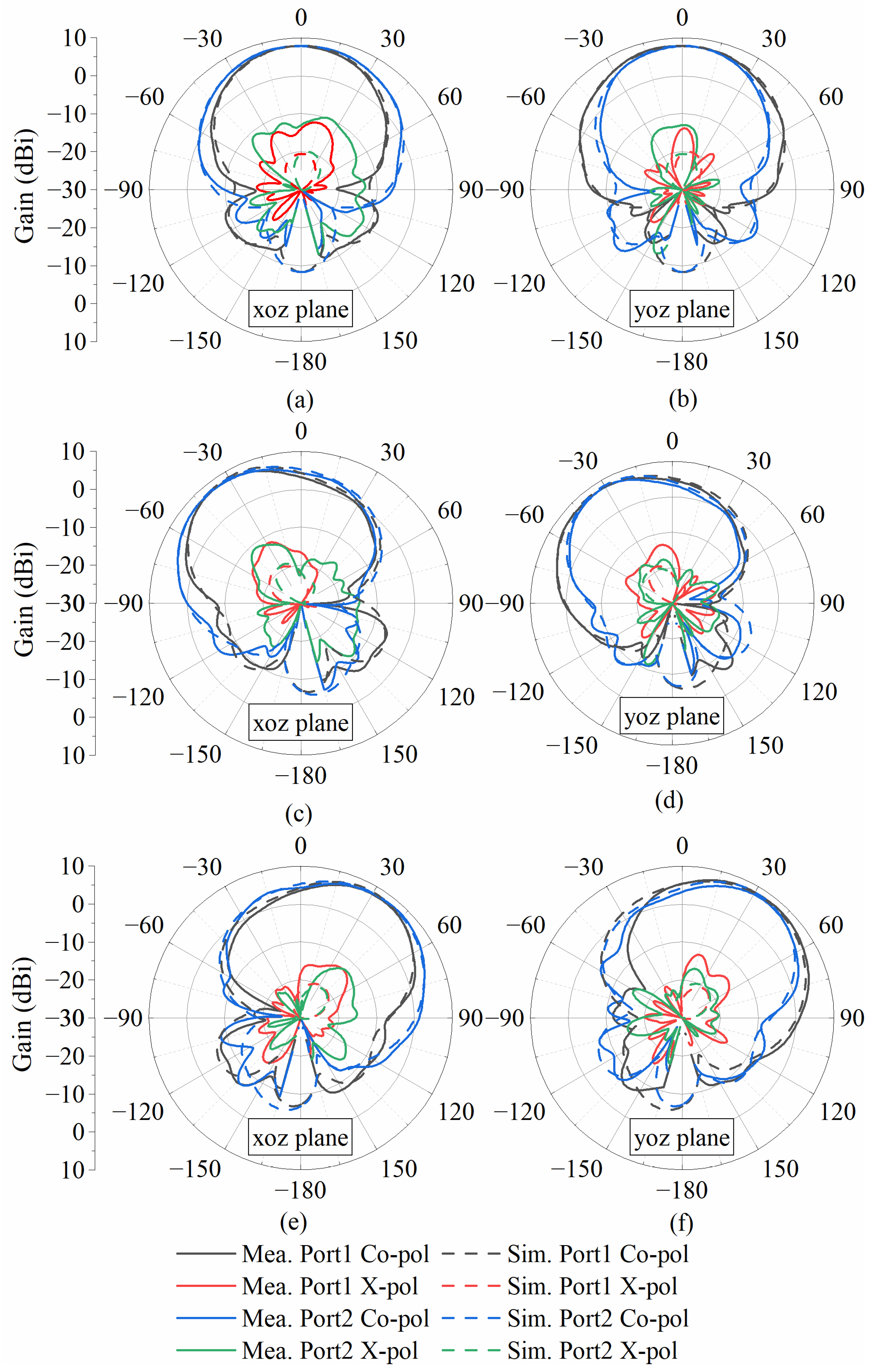
The scanning performance was experimentally tested by a near-field measurement system in an anechoic chamber. The simulated and measured radiation patterns are shown in
Figure 10. The radiation performance was evaluated with two ports individually excited. When one port was connected to the measurement system, another port was connected to a matched load. Due to the symmetric geometry of the antenna, the measured radiation patterns for the two ports were almost the same. The curves of the measured radiation patterns nearly overlapped with the curves of simulated results. Small inconsistencies between the simulated and measured radiation patterns were observed due to measurement error, simulation error, cable effect. For broadside radiation at State I, the measured gain was 7.8 dBi. For State II and III, the beam was steered in its E-plane when Port 1 was fed, while it was steered in its H-plane when Port 2 was excited. For State IV and V, the beam was steered in its H-plane when Port 1 was fed, while it was steered in its E-plane when Port 2 was excited. The measured maximum steering angles were up to ±33° for either of the two ports in the two principal planes. Among the four steering states, the measured average antenna gain was 7.87 dBi. The 0.2~0.4 dB deviations between the measured results and simulated results are attributable to the impacts of the welding and test cables. The simulated radiation efficiencies were about 80%, while the measured radiation efficiencies varied from 77.2% to 83.16% for different states. The cross-polarization was more than 20 dB lower than the co-polarization at the peak directions. A comparison with previously reported electronic beam-steering antenna designs is summarized in
Table 3. The proposed antenna has a wide beam-steering angle, less active components, compact size, and high gain. It can be seen that the proposed antenna has a good balance of the E-plane and H-plane scan angles. In most cases, the coverage efficiency of the beam-scanning antenna tends to increase with both maximum steering angles and gains. Furthermore, the proposed antenna shows good 2D scanning performance for dual polarizations.


 ,
, 


