1. Introduction
In recent years, there has been rapid industrial growth in the use of collaborative robots (cobots) in industry. According to the International Federation of Robotics (IFR), as of 2023, more than 540 thousand industrial robots have been installed worldwide, of which 10.5% are collaborative robots [
1]. The razer difference between traditional manufacturing robots and cobots is that the latter works alongside humans and opens up a new horizon of interaction and cooperation [
2]. Despite their novelty, cobots are rapidly gaining popularity due to their flexibility to work in dynamically changing environments, ease of integration into the manufacturing process, and improved productivity safety [
3,
4]. Cobots also improve the ergonomics of workstations, reducing operator workload and improving production safety [
5,
6].
In the automotive industry, cobots are extremely promising for automating the assembly of complex components, where system flexibility and operator time savings make cobots a promising solution to optimize costs and improve efficiency in the face of changing demand [
7]. Cobots are used in many manufacturing applications, such as assembly, dispensing, finishing, machine tending, material removal, material handling, quality inspection, and welding [
3].
However, despite these advantages, cobots have several limitations that hinder their further proliferation. Their integration requires highly skilled people, and their successful implementation requires significant elaboration on the manufacturing site structure [
8]. This is because although cobots are equipped with sensors for better interaction with the environment and also have support for modern protocols for information exchange, cobots still use outdated programming methods.
The cobots can be programmed online using the teach pendant (handheld terminal), offline programming via specialized CAM systems, and lead-through programming [
9,
10,
11,
12]. In teaching pendant programming, the operator manually sets the robot’s trajectory by moving the robot arm or entering commands through the control panel. This method is suitable only for simple tasks or when minor modifications to the current program are necessary, as the method is extremely time-consuming and requires the operator’s knowledge in the field of robotics and high caution, as well as leads to downtime of the robot line.
By programming through specialized CAM systems, the operator can create complex programs without stopping the working line and simulate the operation of the robotic cell to ensure no collisions and errors. However, this method requires a highly specialized technician who knows robotics and the specific CAM system. If the CAM system is changed (e.g., due to the purchase of a robot from another manufacturer), a retraining procedure must be followed. Moreover, this method is also extremely labor-intensive.
Lead-through programming is a relatively new programming method that is only available to cobots. It allows the robot arm to be moved manually, thus creating trajectories. This method is also an online method and, depending on the complexity of the trajectory, reduces the programming time. However, it is less accurate than teaching pendant programming and requires high skill. For each operation, the operator must manually create approach trajectories to the part in the safety plane, plan the grasp, and return to the safety zone (where the robot can move safely with the part without static and dynamic collisions).
Although cobots have become easier to program compared to classical industrial robots, which are complex to control and require high technical skills, current programming systems still require improvements for convenient interaction [
13]. Robot maintenance and personnel training costs are significant barriers to adopting robotics [
14]. This is especially relevant for small and medium-sized enterprises (SMEs). However, unresolved issues must be addressed to ensure the flexibility and adaptability of cobots in different production environments. Classical programming methods are ineffective for the dynamic manufacturing environments in which cobots are used, requiring the development of control systems [
6].
Cobots also require new control approaches because they interact with humans in the same workspace, and the effectiveness of a collaborative robotic cell depends on the quality of human–robot interaction [
15]. There is a demand for the development of human-centered control systems considering operator convenience and simplicity [
16]. Introducing new control methods for robotic systems that can adapt to operators and variable production processes through the implementation of neural networks and sensor integration will be a key direction in the industry’s future development [
17].
The role of neural networks in controlling and operating cobots continues to expand. The study [
18] analyzes the impact of machine learning on cobot control systems. This allows them to adapt to changing production conditions. Computer vision technology is also important. This technology opens new perspectives for cobots in detecting and interpreting the environment [
19]. Further research can focus on integrating autonomous solutions into cobot control to minimize the dependence on manual control.
The approach proposed in this paper aims to overcome the current limitations by integrating neural network technologies and machine vision systems into collaborative robot control systems. Developing such solutions will increase the level of automation and simplify the introduction of cobots into enterprises.
The paper is divided into five sections. The
Section 1 describes the need to implement a software and hardware solution for human–robot interaction in (SMEs) and educational institutions, given their resource constraints. The
Section 2 describes the research methodology in detail, including the algorithms used, the system architecture, and the process of integrating robotic solutions into a real environment. The
Section 3 contains the experimental results demonstrating the effectiveness of the proposed solution in comparison with traditional methods of programming and controlling robots. The
Section 4 is devoted to a discussion of the development prospects of the proposed system, an analysis of its applicability in various conditions, and a comparison with alternative technologies that can be used to achieve similar goals. The
Section 5 contains conclusions summarizing the study’s key results, emphasizing the significance of the proposed approach.
2. Materials and Methods
The research methodology consists of several steps. The first stage begins with adjusting hardware, such as the projector and cameras mounted above the workspace. An algorithm for calibration is developed to ensure that these devices are properly aligned, which calculates a transformation matrix between the projector and camera to integrate their coordinate system.
Once the calibration is complete, the next step is integrating YOLOv11 to detect and segment objects in the workspace. Before deployment, the YOLO neural network is trained to recognize different components.
The third stage is dedicated to integrating the robot manipulator into the system. Similar to the calibration of the camera projector, a separate calibration algorithm is developed to create a transformation matrix between the camera and the robot.
The experimental system is based on the two-armed cobot ABB YuMi (Zurich, Switzerland), which is equipped with ABB Smart Gripper grippers (Zurich, Switzerland) on each arm [
20]. The unique features of this robot are its compact size, built-in safety system, and the ability to interact closely with a person. The ABB YuMi collaborative robot was designed following ISO/TS 15066 [
21] technical specifications and uses passive risk reduction methods. Passive risk reduction methods involve designing a robot to minimize the potential for serious injury to humans in a collision by limiting the impact force. In particular, the ABB YuMi has lightweight links, limited motor power, and the use of soft materials in its design. The maximum load capacity of each gripper is 200 g, and the working area reaches 1100 mm in diameter. These characteristics make the ABB YuMi robot optimal for performing tasks involving grasping and moving objects in a confined space. The overall system setup and its components are illustrated in
Figure 1.
A high-precision RGB-D Intel RealSense L515 camera (Santa Clara, CA, USA), which uses LiDAR technology, monitors the workspace. Unlike stereo cameras, the L515 camera provides more accurate depth measurement. It allows the capture of a color image with a resolution of up to 1920 × 1080 at a frequency of 30 frames per second and obtaining a depth map with a resolution of up to 1024 × 768 at the same frame rate. The camera is installed in such a way as to cover the entire working area of the robot and provide data for scene analysis and manipulation planning.
Another sensor used in the lab setup is the Leap Motion Controller 2 to provide an intuitive user experience for the operator. This sensor tracks hand movements in real-time and interprets actions such as pointing to an object or selecting actions to translate them into high-level commands afterward. Leap Motion Controller 2 allows tracking under the field of view 160° × 160° and depth between 10 cm (4”) to 110 cm (43”) [
22].
The Acer H5360 projector (New Taipei City, Taiwan) displays the interface on the work surface, providing visual feedback. It allows the robot’s actions, recognized objects, and available actions to be displayed on the table.
A high-performance computing platform based on a Lenovo Legion Pro 5-16IRX8 laptop (Beijing, China) is used for data processing and system management. Its configuration includes an Intel Core i7-13700HX processor, 16 GB of DDR5 RAM, an Nvidia GeForce RTX 4060 GPU with 8 GB of video memory, and a 1 TB SSD. This device runs the system’s key modules, including a computer vision module based on the YOLOv11 library for object detection, a grasp planning module powered by PointNetGPD (
https://github.com/lianghongzhuo/PointNetGPD (accessed 15 March 2025)), and a module for object pose estimation using RANSAC and ICP algorithms provided by the Open3D v0.18 library [
23] to identify correspondences between the part and the point cloud. High computing power allows the system to in real-time, significantly reducing latency for operator commands.
Thus, the CobRA system integrates modern hardware and software solutions to ensure safe, intuitive, and efficient human–robot interaction. Each component plays a key role in achieving the main goal—simplifying the process of controlling robotic systems to perform complex tasks in real time.
2.1. Operating Algorithm
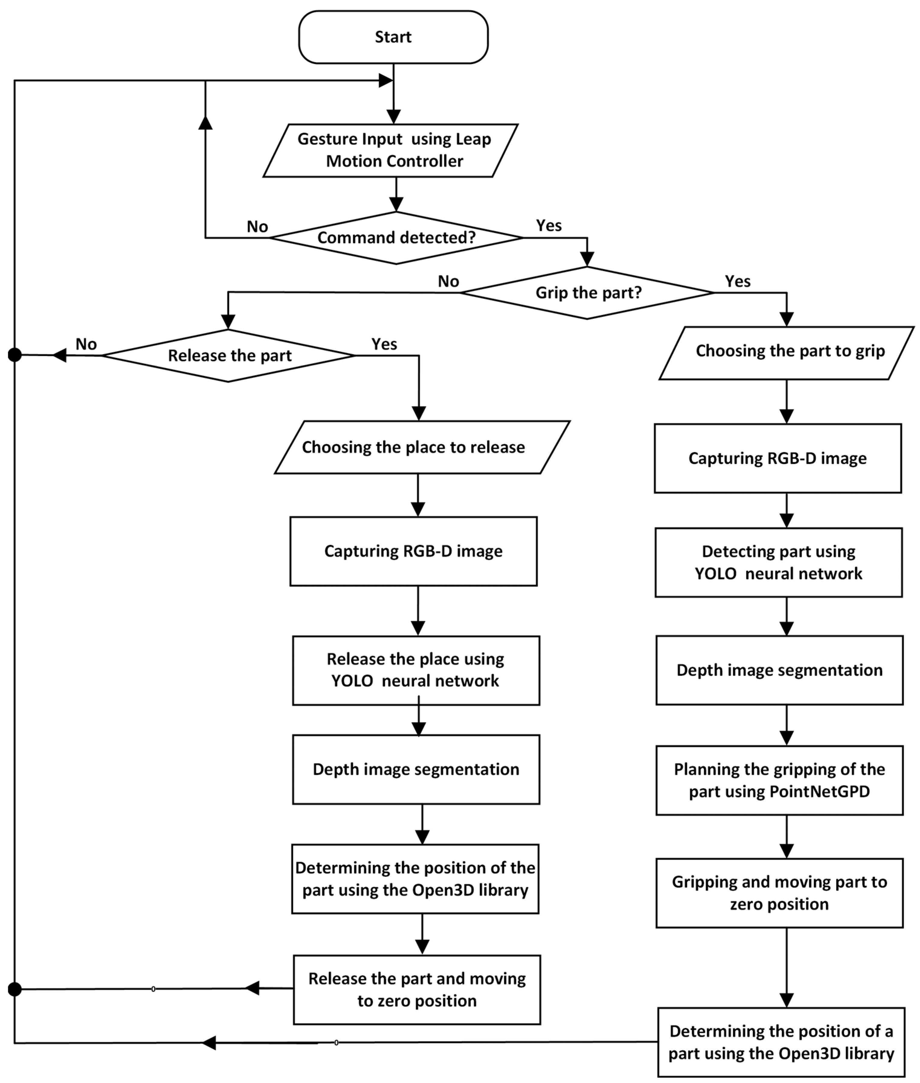
The operation of the CobRA system is based on a structured and sequential workflow designed to ensure efficient and intuitive human–robot interaction. The algorithm, illustrated in
Figure 2, outlines the logical sequence of actions starting from system initialization to the execution of user commands.
Leap Motion is activated for hand key point tracking, the RGB-D camera enters standby mode to capture data on demand, data acquisition pipelines are initialized, and background services are activated. The projector is preparing to display the interface, and the ABB YuMi robot undergoes initialization, including gripper setup and calibration, before moving to its home position.
The Leap Motion controller is a precise input device for controlling the graphical user interface (GUI) and the sequence of operations. The device acts as a sensor that provides raw data about hand movements, which is then processed algorithmically by gesture recognition software Ultraleap Gemini v5.20.0. The application is designed to work exclusively with the “pointing gesture” using the index finger. When this gesture is recognized, the user can only interact with the graphical interface projected on the workspace, thus avoiding accidental errors. The system provides a strong sequence of command execution to prevent incorrect actions. After performing the “grab object” command, only the “release object” command remains available, preventing a second grab where the current object could fall out. Other commands, such as “release object”, are unavailable until the robot grabs a new object.
When the user selects the “grab object” command, the system activates the RGB-D camera to capture an image and a depth map of the workspace. YOLOv11 performs segmentation by identifying the target object and generating an appropriate segmentation mask that isolates it from the background and surrounding objects. The system uses this segmentation mask to refine the object’s boundaries and extracts its exact size, orientation, and position from the depth map. In the next step, PointNetGPD calculates the optimal capture point based on the probability of successful task completion. The ABB YuMi robot then captures and moves the object to the specified location.
When the “release object” command is selected, Leap Motion is used to specify the placement area. The RGB-D camera captures an image and a depth map of the chosen area, and YOLOv11 analyzes the scene and allocates available space. After the scene is cropped, the depth map segmentation specifies the area’s parameters, including size and orientation. The ABB YuMi robot then carefully places the object according to these parameters. After this, the “release object” command becomes unavailable, and the user can only select the “grab object” command.
At each stage of operation, the system provides visual feedback through an interface displayed by the projector. The user sees the robot’s current area of action, the location of objects, and the command execution status. If an operation needs to be adjusted, the user can add a new command via the user interface and the system will automatically recalculate the necessary parameters.
2.2. Software
2.2.1. Calibration
System calibration is necessary to ensure precise interaction between the camera, projector, and robot. Calibration is performed in two stages: first, the camera and projector coordinate systems are synchronized, and then combined with the robot coordinate system.
In the first stage, an RGB-D camera and projector are utilized. The process begins by sending an image containing ArUco markers to the projector. Once the markers are displayed, images are captured using the RGB-D camera via the RealSense SDK, which is converted into a format compatible with the OpenCV library. Using the ArUco module of OpenCV, the system detects and identifies key points of the markers. After verifying the successful recognition of the markers, the camera is calibrated. Input data, including marker points and the camera’s image size, is processed to calculate the camera’s intrinsic parameters, such as focal length, optical center, and distortion coefficients, presented as a
K (1).
In Equation (1), fx and fy represent focal distances, and cx, cy—coordinates of the optical center along the X and Y axes.
The calibration also considers camera distortion, which consists of radial and tangential distortion. Radial distortion is related to the curvature of the camera lens and is described by Equations (2) and (3).
In Equations (2) and (3)
k1,
k2,
k3 are the radial distortion coefficients, and r is the radius of the circle described by Equation (4).
On the other hand, the resulting tangential distortion is because the camera lens and the image plane are not perfectly aligned. The tangential distortion can be described by Equations (5) and (6).
In Equations (5) and (6); p1, p2 represent the tangential distortion coefficients.
In the second step, the coordinates of the robot are aligned with the coordinates of the camera and projector. This is performed using ArUco markers located in three-dimensional space to accurately determine the position and orientation of the robot in space. Equation (7) gives the transformation between the robot and camera coordinate systems:
In Equation (7), Rrobot is a rotation matrix that shows how the robot’s coordinate system is rotated relative to the camera’s coordinate system, and Trobot is a translation vector that specifies the offset of the center of the robot’s coordinate system relative to the camera’s coordinate system.
Additionally, the coordinates of the final actuator, obtained via the Robot Web Server, are used, and the gripper offset is specified based on CAD system drawings. The procedure for the robot follows a similar approach to that used for the camera and projector calibration. However, in this case, during the execution of “solvePnP”, the markers’ coordinates correspond to the robot’s actual position, which is retrieved via the Robot Web Service. The positions of key calibration tool points relative to the base plane of the end effector are taken from the CAD system.
The transformation parameters are calculated and combined into a single homogeneous transformation matrix based on all the collected data. This matrix ensures the correct alignment of the robot, camera, and projector coordinate systems by sequentially applying the transformations using Equation (8):
Calibration results in a single coordinate system that integrates the camera, projector, and robot. Thus, this provides the high positional accuracy required for automated tasks such as object manipulation, projection control and robot interaction with the environment.
2.2.2. YOLOv11
The software of the CobRA system contains advanced technologies for effective interaction between a human and a robot. The main structure of the system consists of a computer vision module based on YOLOv11 for object detection, a grasp planning module using PointNetGPD, and a point cloud processing module leveraging the Open3D library. This combination allows for real-time data processing, converting user commands into high-level robot actions and providing feedback to the operator.
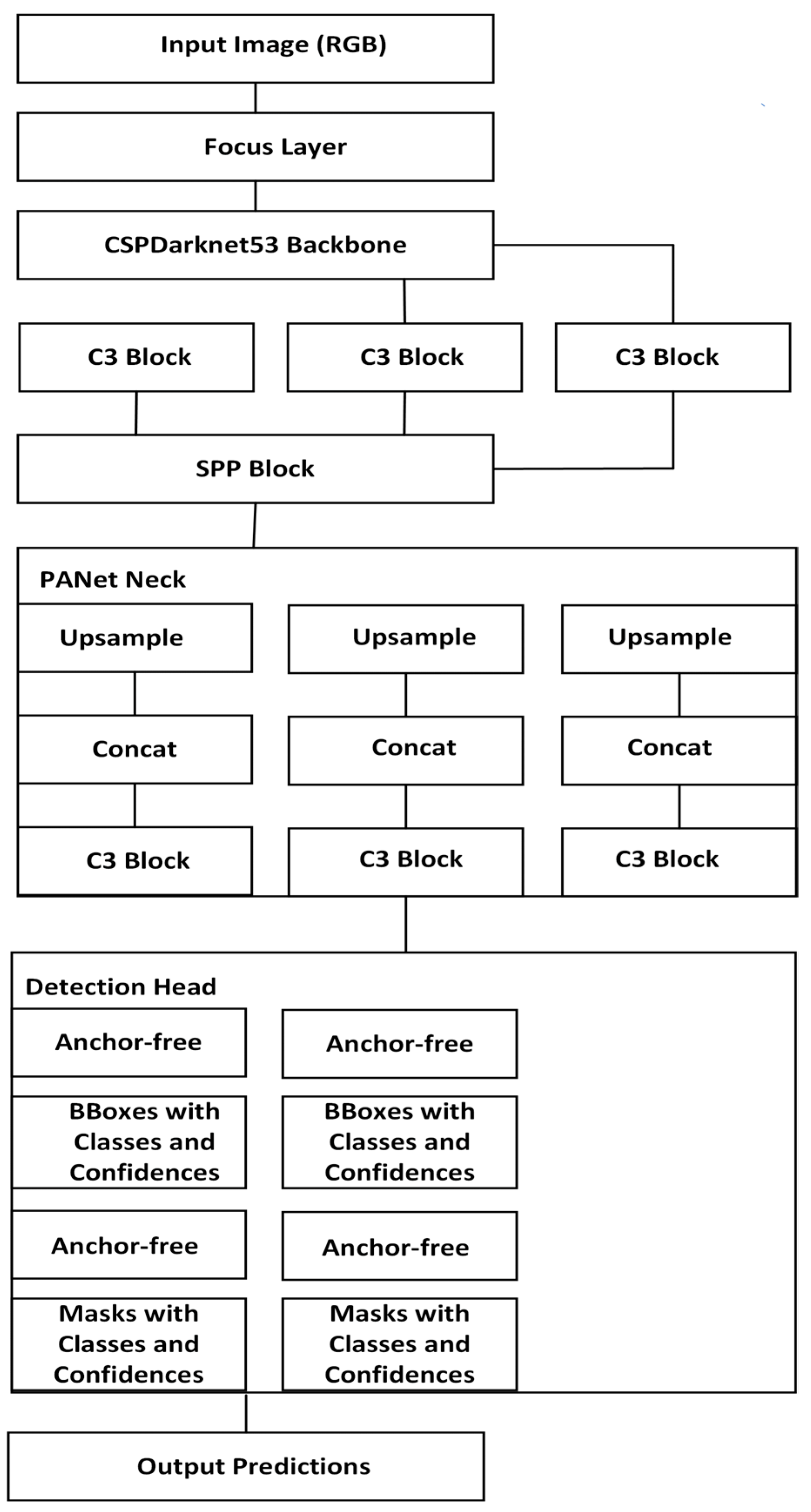
YOLOv11 is the key element of the system and is responsible for object detection and scene analysis. It processes real-time visual data from the RGB-D camera to identify and localize objects in the robot’s work area. The structure of this convolutional neural network (CNN) is shown in
Figure 3.
Its architecture consists of three key components—Backbone, Neck, and Head, each of which plays an important role in the detection process. The architecture starts with the Input Layer, which takes an RGB image. The input image contains the data needed for further analysis.
The Focus Layer, which follows the Input Layer, transforms the data by combining neighboring pixels to reduce the image size and prepare it for further processing. The Backbone is the core part of YOLO and is designed to extract features from the input image. This part of the network processes the image, converting it into a feature map containing information about objects’ textures, edges, and other characteristics. The Backbone consists of C3 Blocks and SPP Blocks (Spatial Pyramid Pooling). C3 Blocks pass important information through the layers, preventing gradient disappearance. SPP Block combines information from different spatial scales to improve the successful recognition of objects.
After the Backbone is the PANet Neck, which improves the quality of features and combines them; the PANet Neck contains three main components: Upsample, Concat, and C3 Blocks. Upsample is used to improve the feature map and restore previously lost details. Concat creates a more informative feature map by combining features from different depth levels. C3 Blocks in PANet Neck perform the same functions as in Backbone, facilitating the transfer of information across layers.
The head is the component responsible for the final object detection and segmentation. Using the processed features from the Neck, it predicts the coordinates of the bounding boxes and the probability of the presence of objects in these boxes. It provides pixel-level boundaries for objects in the image. The head consists of several convolutional layers that provide high accuracy in object detection and segmentation accuracy.
Finally, the Output Layer processes the results obtained from the head and prepares them for visualization.
2.2.3. Module for Object Pose Estimation
The Module for Object Pose Estimation is crucial as it is necessary for determining the position of the gripped part for correct insertion since the PointNetGPD neural network is only responsible for gripping planning. The workflow for this module is illustrated in
Figure 4.
This module starts by downloading a segmented raw point cloud from the scan tool. Along with the point cloud, a 3D model of the target object is loaded in STL format, representing surfaces as triangular meshes. Therefore, the STL files must be converted into a discrete point cloud for alignment. Once converted, the 3D model is scaled from millimeters to meters to ensure consistent measurements. Next, the model is transformed into a fixed-sized point cloud.
Before alignment, the point cloud undergoes a preprocessing stage to remove noise and outliers. First, a statistical outlier removal method is applied to eliminate points that deviate significantly from their local neighborhoods. The density filtering method removes the sparse points for a purer dataset.
Next, normals are estimated for the point cloud and 3D model to facilitate feature extraction and alignment. Vectors of these normals are required to establish reliable correspondences between the two datasets. However, due to differences in scanning conditions, the orientation of the normal vectors may be inconsistent and need to be corrected afterward.
Preliminary alignment brings the model closer to the point cloud before applying more sophisticated methods. During this step, the center points of both datasets are calculated, and the model’s center is aligned with the center of the point cloud. After this, Principal Component Analysis (PCA) based alignment is applied to orient the model along the major axes of the point cloud. This method provides a coarse transformation to minimize the mismatch.
Additional methods are used to analyze the geometric properties of the point cloud to ensure reliable alignment. The system uses fast point feature histograms (FPFH) to compactly and discriminatively describe local point surface features. These descriptors are computed for a reduced version of the point cloud to improve efficiency while preserving important geometric details. FPFH descriptors help to identify key features of the model and point cloud, forming the basis for establishing robust correspondences between the two datasets.
After feature extraction, the algorithm performs a rough alignment using RANSAC (Random Sample Consensus), which ensures that the FPFH descriptors between the point cloud and the model are matched. In this initial alignment step, correspondences are refined, and outliers are discarded.
Finally, the refinement process starts with an intermediate alignment using the It-erative Closest Point (ICP) algorithm. The final step is a visual check of accuracy and evaluation of goodness of fit and root mean square error (RMSE).
2.2.4. Data Transformation
The data conversion process starts by capturing an RGB-D image consisting of a color image, given in Equation (9), for visual information and a depth map, shown in Equation (10), to encode the distance of each pixel from the camera.
In Equations (9) and (10), H represents height, W is the width.
The depth map ID is then converted into a 3D point cloud P where each point pi(xi,yi,zi) is computed using the camera’s intrinsic parameters.
The YOLO neural network processes the RGB image
IRGB to detect and localize the object of interest. YOLO creates a bounding box that defines the region of interest (ROI):
where
xmin,
ymin,
xmax,
ymax are the coordinates of the object’s bounding box. The network applies convolutional layers to extract features
FYOLO and predicts the ROI using a classification and regression model (12):
In Equation (12), Wconv represents a convolutional filter in a neural network that extracts spatial features from the input image by detecting patterns such as edges, textures, and object structures during convolution operations.
Using the
ROI R, the point cloud
P is segmented to focus exclusively on the object. The segmented point cloud
PROI contains only the points within the
ROI:
The segmented point cloud
PROI is passed to the PointNet neural network to evaluate grasping candidates. Each point
pi in
PROI is individually processed by a shared Multi-Layer Perceptron (MLP) to extract local features:
where
ϕ is the MLP. Max-pooling is applied to aggregate global features across all points:
The global feature vector
Fglobal is concatenated with local features f
i:
The combined feature vector is passed through fully connected layers to predict the probability of a successful grasp:
In Equation (17) Wfc, bfc are the weights and biases of the fully connected layer.
Finally, after evaluating all candidates, the best grasp
g* is selected using Equation (18).
In this way, the robot moves its arm to the selected pose g*, performs gripping and checks stability using force and torque sensors.
2.3. Neural Networks Training
2.3.1. YOLOv11 Training
Discovering the full potential of neural networks such as YOLOv11 and PointNetGPD requires training them on high-quality and diverse data. The training process allows the model to adapt to real-world conditions and solve object detection tasks efficiently. The current study used 261 images to train the YOLO neural network and 33 images to validate it. The training was based on factors such as orientation, scale, and position of objects in the scene.
To achieve high detection accuracy, optimized hyperparameters such as epochs, batch size, input image size, learning rate, momentum, weight decay, Intersection over Union (IoU) threshold and confidence threshold were used. The values of these parameters are given in
Table 1.
Metrics such as Precision, Recall, and F1-Score were used to evaluate the model’s performance.
Precision is the probability that an object detected by the model is correct. On the other hand, Recall describes the proportion of detected objects among all existing objects in the scene. F1-Score is the harmonic average between Precision and Recall.
2.3.2. PointNetGPD Training
A dataset of 58,500 training and 4500 test samples was used to develop and validate the PointNetGPD model. The dataset included various point cloud data representing objects of different shapes, sizes, and complexity. Each sample was labeled with successful and unsuccessful capture results. Hyperparameters and their values and descriptions are given in
Table 2.
3. Results
3.1. Calibration Results
The CobRA system was calibrated to ensure accurate matching of the RGB-D camera, projector, and ABB YuMi robot, producing the K matrix and rotation (rvec) and translation (tvek) vectors for the four markers.
The internal parameters of the RGB-D camera were characterized as follows:
From matrix K, the focal distances and center position were obtained.
The center has the coordinates (1258.78 and 1255.17), and the focal distance on the coordinate X equals 286.927; on the coordinate Y, it equals 106.129.
Rotation and displacement vectors for the first marker:
Rotation and displacement vectors for the second marker:
Rotation and displacement vectors for the third marker:
Rotation and displacement vectors for the fourth marker:
During the calibration accuracy determination, the RMS error was obtained. It was only 0.0752353 mm, demonstrating a slight variation in the internal and external parameters of the camera.
3.2. YOLOv11 Performance Results
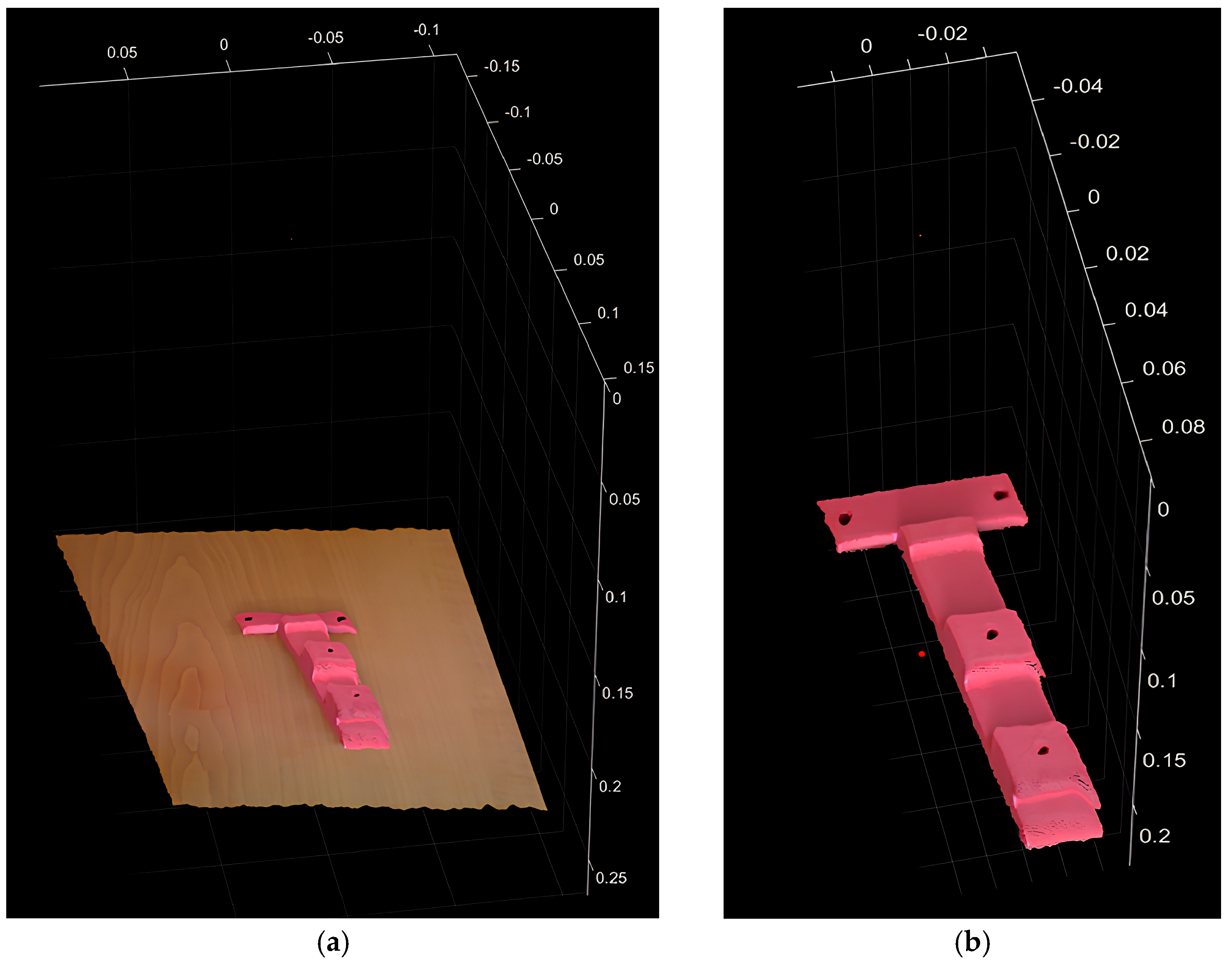
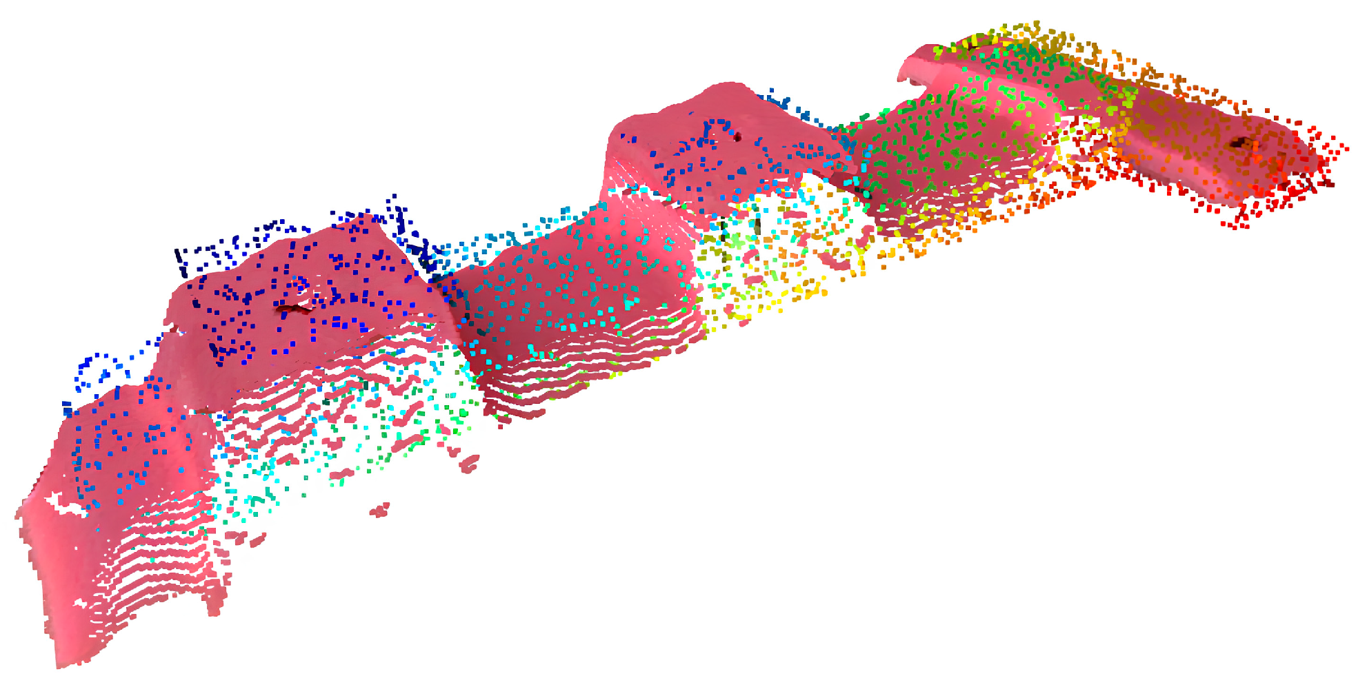
The results of using YOLOv11 were based on a comprehensive comparison between the raw data and the segmented results.
Figure 5a shows raw data that covers the entire scene without prior segmentation or filtering. This raw data represents the raw spatial distribution of detected objects and environment.
In contrast,
Figure 5b shows segmented output data obtained using YOLObv11. After segmentation, the data are refined by highlighting detected objects and removing irrelevant background elements.
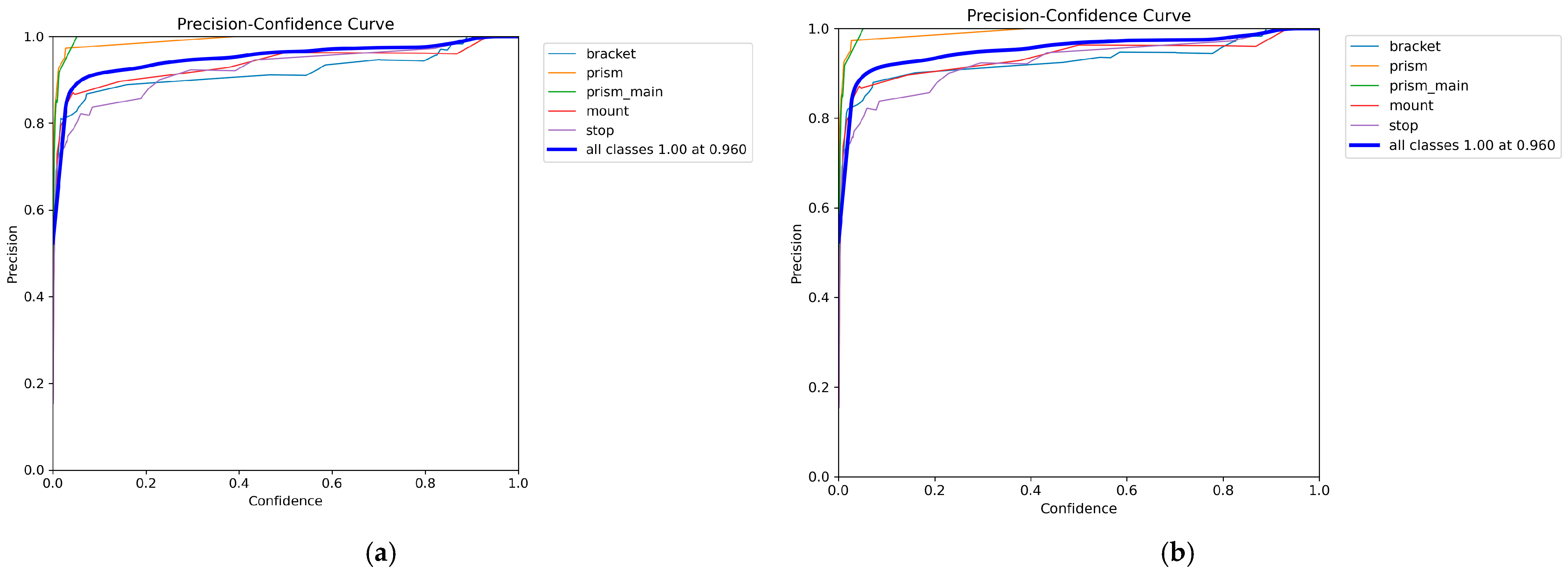
The curves of accuracy metrics, completeness metrics, F1 metrics, and the distribution of classes and correlations between object parameters were analyzed to evaluate the performance of the YOLO model. The analyses were performed for objects at levels of representation, such as the Bounding Box and Segmentation Mask. Precision–Confidence curves are presented in
Figure 6a,b for different levels of representation of the model.
When confidence levels are above 0.6, the accuracy of bounding boxes and masks remains consistently high, indicating the model’s ability to minimize false positives.
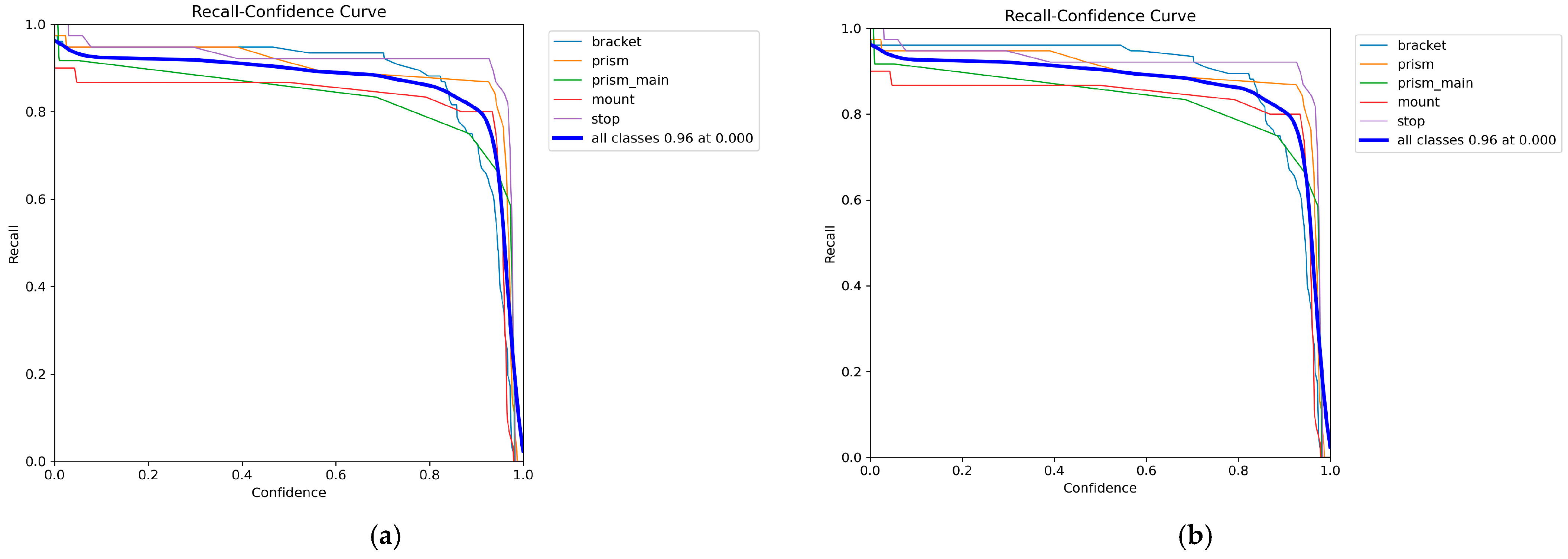
Figure 7a,b show the Recall–Confidence curves reflecting the model’s ability to identify most objects in the scene.
As can be seen from the curves, the maximum completeness values are achieved at low confidence levels, indicating YOLO’s resistance to missing sparse or partially occluded elements.
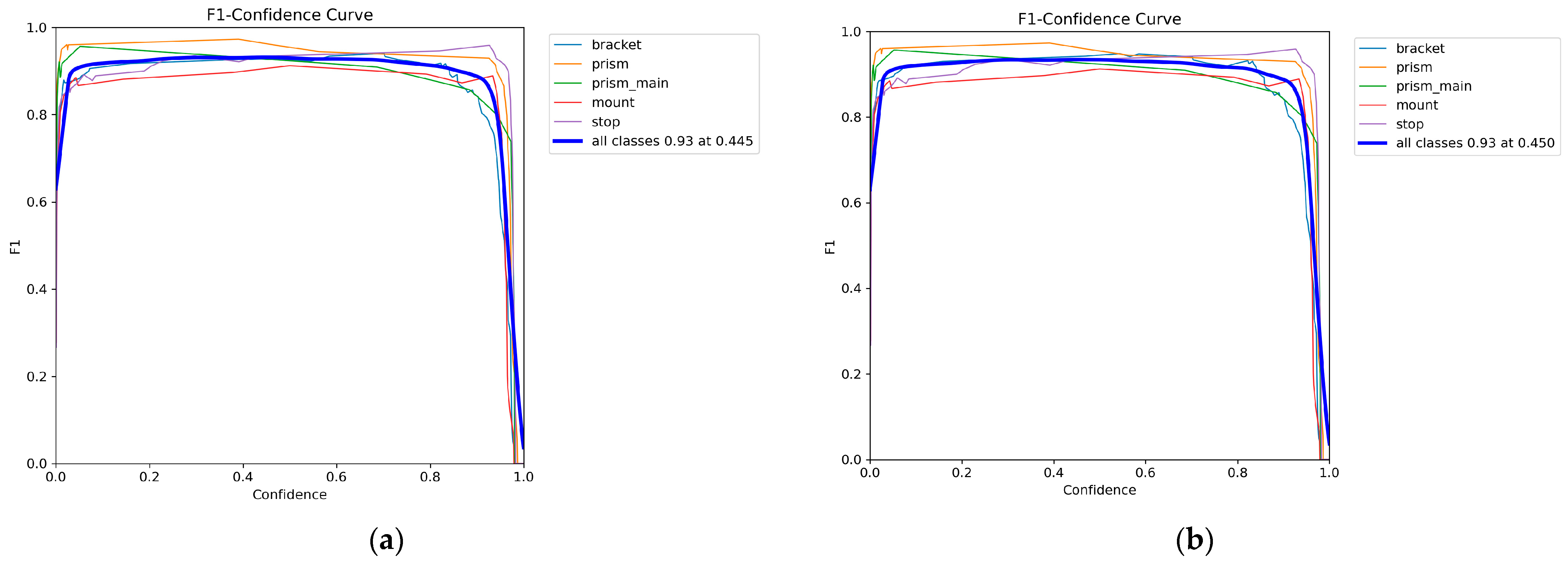
F1 curves are shown in
Figure 8a for the bounding box and in
Figure 8b for the mask.
As can be seen from the plots, the model achieves an optimal balance between Precision and Recall at confidence levels of ~0.45. However, the mask F1 metric shows higher values, confirming the benefits of segmentation for complex objects.
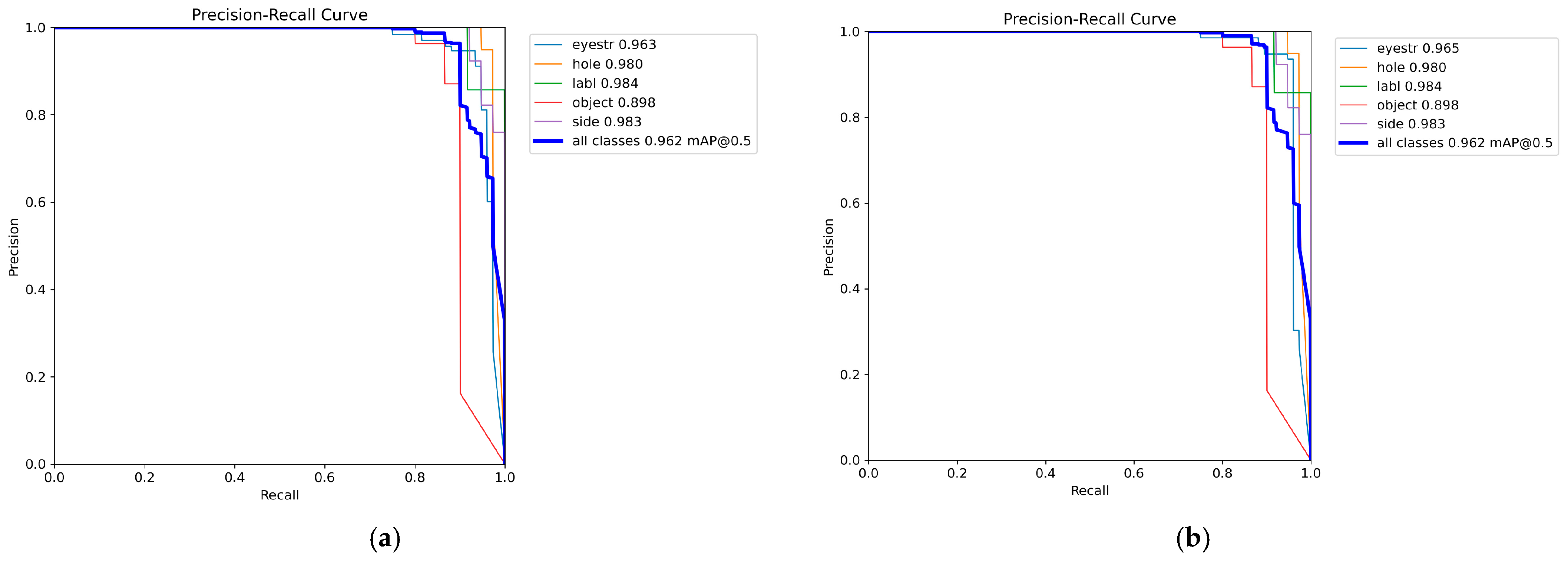
Precision–Recall (PR) curves for bounding boxes and masks are shown in
Figure 9a,b.
As can be seen from the graphs, although the bounding boxes contain a high level of average accuracy (~0.93), the use of a mask allows it to be increased to ~0.96. Thus, this shows the ability of the model to detect and localize objects in the scene with minimal false positives and false negatives.
3.3. PointNetGPD Performance Results
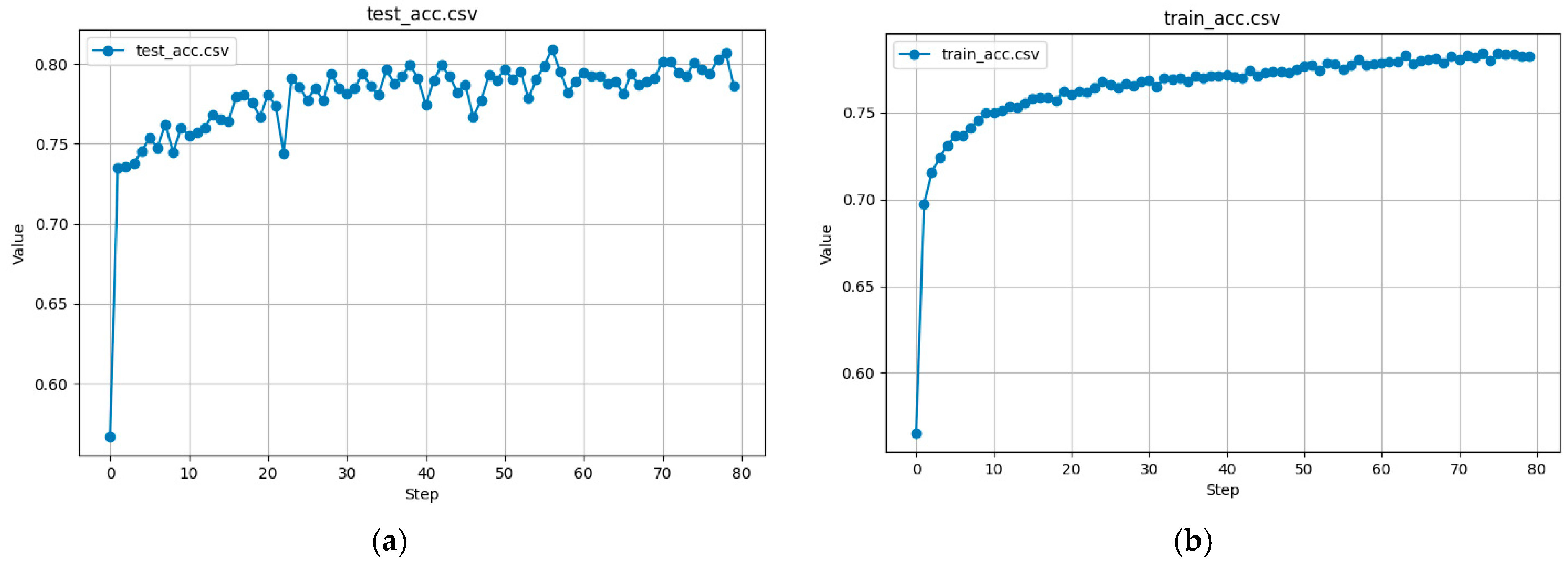
To assess the performance of the PointNetGPD model, the training and test datasets were analyzed using key metrics, including accuracy, precision, recall, F1-Score, AUROC (area under the receiver operating characteristic curve), and loss function. These metrics allow evaluation of the model’s ability to distinguish between successful and unsuccessful capture points while providing generalization to unknown data.
The accuracy of the test and trained data, shown in
Figure 10a,b, respectively, was obtained as the proportion of correctly classified grasping poses (successful and unsuccessful) among all predictions.
The training accuracy curve steadily increases, confirming that the model is learning meaningful grasp patterns. The test set’s accuracy stabilizes at ~80%, indicating that the model generalizes well and maintains high prediction confidence.
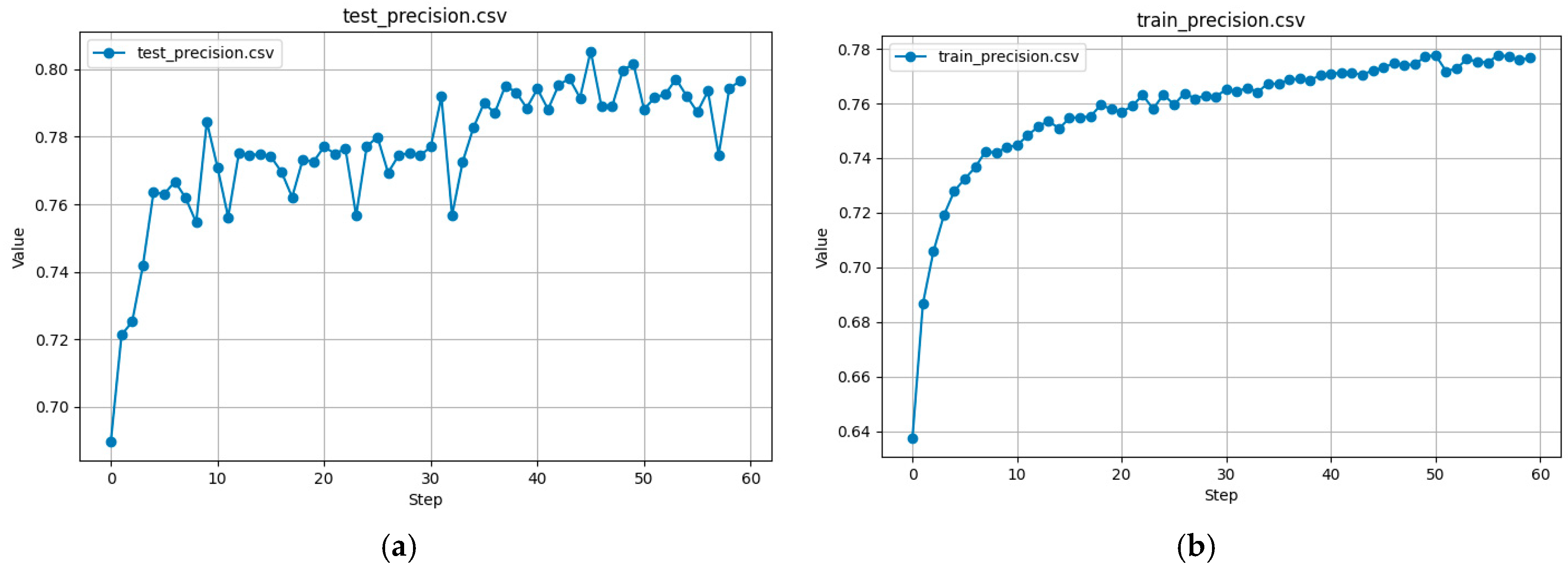
Precision and Recall are two crucial metrics for evaluating the grasp detection performance of the PointNetGPD model. Precision measures the proportion of grasp points predicted as successful that are correct. On the other hand, Recall l measures the proportion of actual successful grasps that the model correctly identifies.
Precision curves for test and training data are shown in
Figure 11a,b.
These figures demonstrate that the training precision curve steadily increases over epochs, which allows for better predictions. At the same time, the precision for the test data stabilizes at ~80%, indicating that the model effectively eliminates most of the false positive capture points.
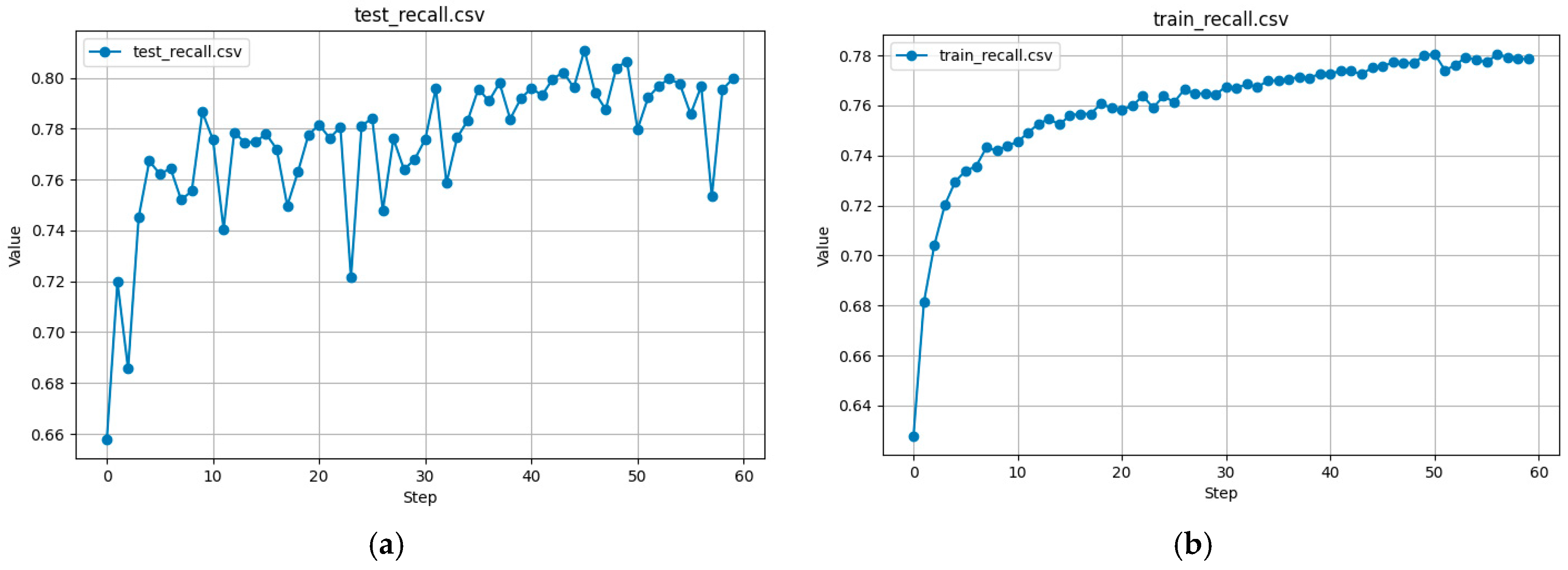
Recall curves for test and training data are shown in
Figure 12a,b.
The training data for the Recall curve as well as for the Precision curve show a gradual improvement. At the same time, for the test data, recall reaches ~85%.
F1-Score is the harmonic mean of precision and recall, balancing the trade-off between false positives and false negatives. F1 curves for test and training data are shown in
Figure 13a,b.
The training F1 curve continuously improves, reaching ~0.78, while the test F1 stabilizes at ~0.80. Thus, this indicates that the model maintains a good balance between precision and recall.
AUROC evaluates the model’s ability to differentiate between successful and unsuccessful grasps across various confidence thresholds. AUROC for test and training data are shown in
Figure 14a,b.
The training AUROC curve steadily increases, demonstrating the effectiveness of training, and the test AUROC reaches ~0.88. Those values indicate that the model maintains high confidence in distinguishing between positive and negative capture candidates.
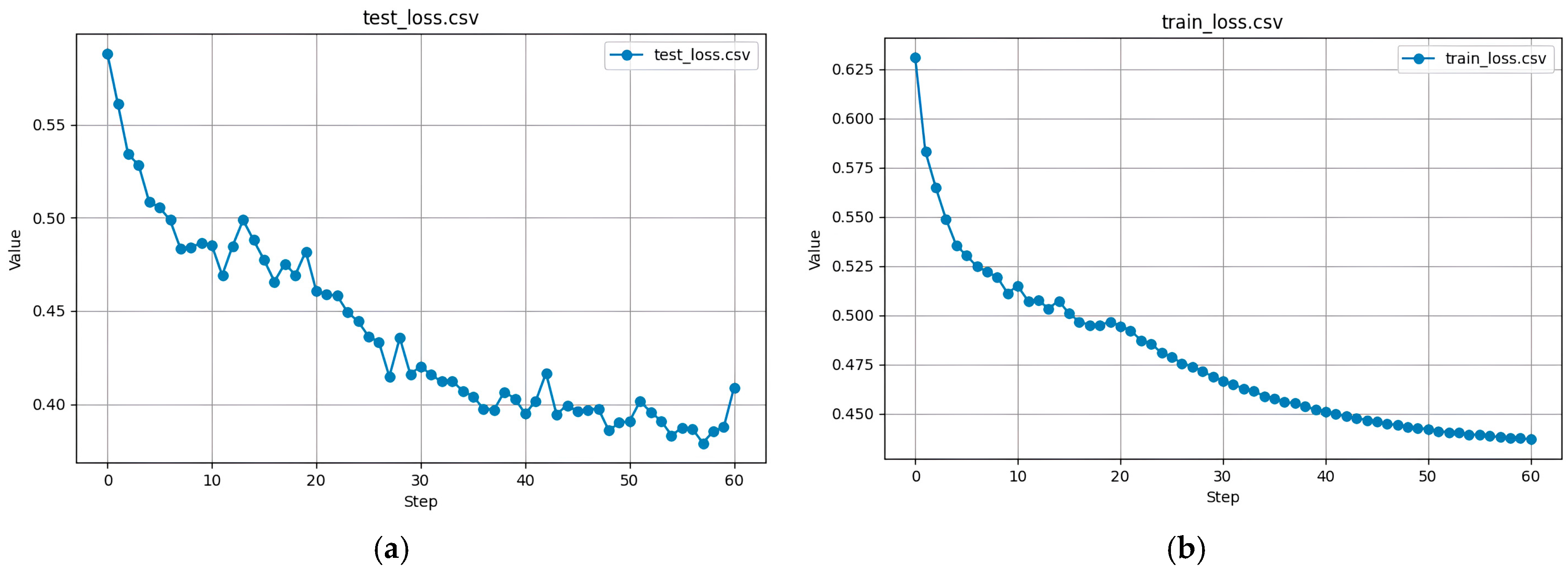
The loss function measures the difference between predicted and actual grasp classifications. The loss function for test and training data is shown in
Figure 15a,b.
According to
Figure 15, the training loss curve gradually decreases; in the test dataset, the loss stabilizes around 0.40. Thus, the model effectively captures grasping patterns without overfitting to training data.
3.4. Results of Object Pose Estimation
The estimation of the object position was completed using a module based on the Open3D library. The operation of this module started with the data preparation phase.
During the data preparation phase, the initial point cloud contained 145,670 points, representing the entire workspace, including noise and irrelevant data points. This raw point cloud data underwent preprocessing, including statistical outlier removal (6452 noisy points removed) and radius-based filtering (6452 sparse points removed), resulting in a cleaner dataset.
Feature extraction using Fast Point Feature Histograms (FPFH) was performed on the downsampled point cloud and model, each containing 5000 points. The computed descriptors had a shape of (33, 5000) for both the cloud and model, forming the basis for robust alignment.
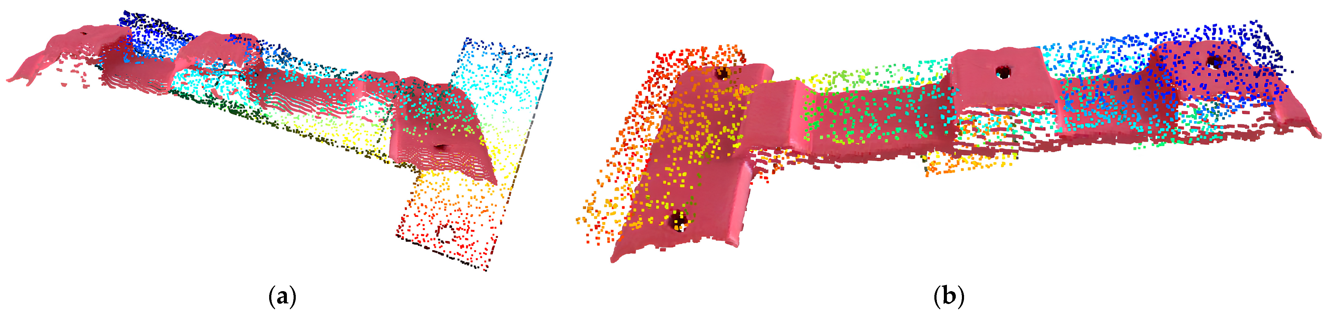
During the alignment phase, PCA-based rough alignment established an initial orientation, followed by RANSAC-based coarse alignment, which yielded a fitness score of 0.8073, an inlier RMSE of 0.00545 m, and strong feature correspondences. The point cloud image of part after PCA and RANSAC are illustrated in
Figure 16a,b.
The nearest neighbor alignment errors for RANSAC were:
- –
Mean error: 0.00354 m;
- –
Max error: 0.01341 m;
- –
Median error: 0.00304 m.
The ICP refinement phase further improved the alignment, achieving a fitness score of 0.8187 with an inlier RMSE of 0.00234 m. The nearest neighbor alignment errors after ICP were:
- –
Mean error: 0.00195 m;
- –
Max error: 0.00967 m;
- –
Median error: 0.00168 m.
The point cloud image of a part after ICP is illustrated in
Figure 17.
These results indicate that the alignment process successfully minimizes the discrepancies between the scanned point cloud and the 3D model while maintaining geometric consistency. Thus, the achieved accuracy demonstrates the effectiveness of the module for object pose estimation.
4. Discussion
The key difference between the proposed approach and similar solutions is the high degree of autonomy of the robotic cell. For example, in [
24], a system for remote controlling an industrial robot using gestures and voice commands is proposed [
24]. According to the authors [
25], the solution is cost-effective and versatile. The authors developed a system that can recognize a wide range of gestures, allowing the operator to send commands to the robot with low latency intuitively. However, the proposed gesture and voice control system is limited to the robot’s movement only, and the proposed system does not consider the possibility of controlling the robot’s end effector. Therefore, the proposed system cannot completely replace traditional teaching pendants.
In the study by Nuzzi et al. [
25], a more advanced system for controlling industrial robots using gestures is presented. The developed system utilizes the Robot Operating System (ROS) [
25], which provides a universal way of interacting with industrial equipment and, as a result, greatly enhances the versatility and ease of system integration. The system was tested for practical validation when assembling a Moka coffee machine. This validation confirmed the potential applicability of the system in real production processes. However, one of the drawbacks is that the robot does not automatically recognize objects when performing a grip: the operator manually sets the grip point. This approach is unsuitable for working with fragile parts or in cases where the optimal or acceptable grip point is not obvious to a person.
In the proposed solution, PointNetGPD neural network training can be carried out based on a synthetically generated dataset, which allows for integrating physical simulation and considering parameters such as fragility, friction coefficient, and other mechanical characteristics of materials [
26]. It reduces the possibility of errors in selecting grip points. In addition, operations such as “grap part” or “install part” significantly simplify the programming process [
27]. Also, unlike the gesture interfaces proposed by similar works, CobRA uses simplified gestures based on a “virtual touch surface”, making the system more intuitive and not requiring memorizing gestures.
An additional advantage of the proposed approach is the possibility of working with unsorted objects and capturing them directly from the conveyor. Consequently, this reduces requirements for pre-preparation of parts and simplifies the technological process.
Despite the advantages of the proposed method, it also contains some limitations. In some cases, incorrect object orientation determination by RANSAC and ICP is possible. For example, incorrect orientation determination may occur when processing parts with symmetrical surfaces since their position is difficult to identify correctly. In addition, object detection accuracy depends on the fine-tuning of the RANSAC and ICP parameters, which are sensitive to the current configuration of the workplace, such as camera parameters, surface characteristics of parts and the workplace, and other environmental factors. This problem can be addressed by using high-precision laser sensors to accurately detect the position of the part in the gripper and using soft pads on the gripper fingers to compensate for possible recognition errors.
In the future, it is planned to implement automation of production preparation, in which the worker loads a 3D model of the manufactured unit to the system, and the system automatically generates a synthetic dataset for training neural networks, which are then trained and verified. The possibility of introducing a digital twin is also being considered since the available set of collected data allows for modeling the system’s behavior in a virtual environment. In particular, before directly capturing an object in the real world, it is possible to simulate the process of gripping a part and verify grasp quality. In addition, an important area of further development is to improve the accuracy of object position detection algorithms, improve resistance to environmental noise, and increase the system’s overall reliability.
5. Conclusions
The CobRA system developed uses advanced technology to simplify robot handling. It is based on computer vision to detect objects in the workspace. Neural network algorithms help recognize details and determine optimal pick-up points, while an interactive interface with workstation projection facilitates robot control. In addition, the system supports gesture control via the Leap Motion Controller, making it even more user-friendly and intuitive.
The experimental part of the study involved testing CobRA in the SmartTechLab environment, where it proved its effectiveness [
28].
The experimental results demonstrated the system’s high accuracy. YOLOv11 achieved 93% accuracy for Bounding Box, and 96% for Segmentation Mask, and the PointNetGPD algorithm achieved 80% successful capture point predictions on the test data. The system calibration accuracy was 0.075 mm, minimizing positioning errors. These metrics show that CobRA simplifies cobot operations by reducing programming time and errors.
The advantages of CobRA over traditional methods are obvious. Unlike existing platforms, CobRA allows operators without technical skills to program the robot easily and work with unsorted objects. Therefore, this makes the system suitable for use in real production environments.
In conclusion, CobRA represents a significant step forward in human–robot interaction, making cobot control intuitive and accessible even to unskilled users.
Author Contributions
Conceptualization, V.A.; methodology, O.S. and V.A.; software, V.A.; validation, V.A.; formal analysis, O.S., A.I. and V.I.; investigation, O.S., V.A., A.I. and V.I.; resources, A.I.; data curation, O.S., V.A., A.I. and V.I.; writing—original draft preparation, O.S. and A.I.; writing—review and editing, V.A. and V.I.; visualization, V.A.; supervision, V.I.; project administration, O.S.; funding acquisition, V.I. All authors have read and agreed to the published version of the manuscript.
Funding
This work was supported by the Slovak Research and Development Agency under contract No. APVV-19-0590, by the EU NextGenerationEU through the Recovery and Resilience Plan for Slovakia under the projects 09I03-03-V01-00094, 09I03-03-V01-00095, 09I03-03-V01-00102 and by the projects VEGA 1/0061/23, KEGA 022TUKE-4/2023 granted by the Ministry of Education, Science, Research and Sport of the Slovak Republic, The NAWA Ulam Programme (grant number BPN/ULM/2022/1/00045), and the International Association for Technological Development and Innovations.
Data Availability Statement
Data are contained within the article.
Conflicts of Interest
The authors declare no conflicts of interest.
References
- IFR International Federation of Robotics. Collaborative Robots-How Robots Work Alongside Humans. Available online: https://ifr.org/ifr-press-releases/news/how-robots-work-alongside-humans (accessed on 9 February 2025).
- Bauer, J.C.; Abdous, M.-A.; Kurscheid, S.; Lucas, F.; Lozenguez, G.; Daub, R. Towards Enabling Human-Robot Collaboration in Industry: Identification of Current Implementation Barriers. In Proceedings of the 5th Conference on Production Systems and Logistics, Stellenbosch, South Africa, 6–8 November 2023. [Google Scholar] [CrossRef]
- Montini, E.; Daniele, F.; Agbomemewa, L.; Confalonieri, M.; Cutrona, V.; Bettoni, A.; Rocco, P.; Ferrario, A. Collaborative Robotics: A Survey From Literature and Practitioners Perspectives. J. Intell. Robot. Syst. 2024, 110, 117. [Google Scholar] [CrossRef]
- Kopp, T.; Baumgartner, M.; Kinkel, S. Success Factors for Introducing Industrial Human-Robot Interaction in Practice: An Empirically Driven Framework. Int. J. Adv. Manuf. Technol. 2021, 112, 685–704. [Google Scholar] [CrossRef]
- Taesi, C.; Aggogeri, F.; Pellegrini, N. COBOT Applications—Recent Advances and Challenges. Robotics 2023, 12, 79. [Google Scholar] [CrossRef]
- Cardoso, A.; Colim, A.; Bicho, E.; Braga, A.C.; Menozzi, M.; Arezes, P. Ergonomics and Human Factors as a Requirement to Implement Safer Collaborative Robotic Workstations: A Literature Review. Safety 2021, 7, 71. [Google Scholar] [CrossRef]
- Polonara, M.; Romagnoli, A.; Biancini, G.; Carbonari, L. Introduction of Collaborative Robotics in the Production of Automotive Parts: A Case Study. Machines 2024, 12, 196. [Google Scholar] [CrossRef]
- Weidemann, C.; Mandischer, N.; Van Kerkom, F.; Corves, B.; Hüsing, M.; Kraus, T.; Garus, C. Literature Review on Recent Trends and Perspectives of Collaborative Robotics in Work 4.0. Robotics 2023, 12, 84. [Google Scholar] [CrossRef]
- Vladimirov, B.; Nikolov, S.; Tsolov, S. Programming Industrial Robots in the Fanuc ROBOGUIDE Environment. Eng. Proc. 2024, 70, 20. [Google Scholar] [CrossRef]
- Obal, P.; Gierlak, P. EGM Toolbox—Interface for Controlling ABB Robots in Simulink. Sensors 2021, 21, 7463. [Google Scholar] [CrossRef] [PubMed]
- Ruzarovsky, R.; Horak, T.; Bocak, R. Evaluating Energy Efficiency and Optimal Positioning of Industrial Robots in Sustainable Manufacturing. J. Manuf. Mater. Process. 2024, 8, 276. [Google Scholar] [CrossRef]
- Wu, H.; Deng, H.; Yang, C.; Guan, Y.; Zhang, H.; Li, H. A Robotic Off-line Programming System Based on SolidWorks. In Proceedings of the 2015 IEEE Conference on Robotics and Biomimetics, Zhuhai, China, 6–9 December 2015; pp. 1711–1716. [Google Scholar] [CrossRef]
- Liu, D.; Cao, J. Determinants of Collaborative Robots Innovation Adoption in Small and Medium-Sized Enterprises: An Empirical Study in China. Appl. Sci. 2022, 12, 10085. [Google Scholar] [CrossRef]
- Keshvarparast, A.; Battini, D.; Battaia, O.; Pirayesh, A. Collaborative Robots in Manufacturing and Assembly Systems: Literature Review and Future Research Agenda. J. Intell. Manuf. 2024, 35, 2065–2118. [Google Scholar] [CrossRef]
- Picco, E.; Miglioretti, M.; Le Blanc, P.M. Sustainable Employability, Technology Acceptance and Task Performance in Workers Collaborating with Cobots: A Pilot Study. Cogn. Technol. Work. 2024, 26, 139–152. [Google Scholar] [CrossRef]
- Gualtieri, L.; Rauch, E.; Vidoni, R. Emerging Research Fields in Safety and Ergonomics in Industrial Collaborative Robotics: A Systematic Literature Review. Robot. Comput.-Integr. Manuf. 2021, 67, 101998. [Google Scholar] [CrossRef]
- Gualtieri, L.; Palomba, I.; Wehrle, E.J.; Vidoni, R. The Opportunities and Challenges of SME Manufacturing Automation: Safety and Ergonomics in Human–Robot Collaboration. In Industry 4.0 for SMEs; Matt, D.T., Modrák, V., Zsifkovits, H., Eds.; Springer International Publishing: Cham, Switzerland, 2020; pp. 105–144. ISBN 978-3-030-25424-7. [Google Scholar]
- Borboni, A.; Reddy, K.V.V.; Elamvazuthi, I.; AL-Quraishi, M.S.; Natarajan, E.; Azhar Ali, S.S. The Expanding Role of Artificial Intelligence in Collaborative Robots for Industrial Applications: A Systematic Review of Recent Works. Machines 2023, 11, 111. [Google Scholar] [CrossRef]
- Liu, L.; Schoen, A.J.; Henrichs, C.; Li, J.; Mutlu, B.; Zhang, Y.; Radwin, R.G. Human Robot Collaboration for Enhancing Work Activities. Hum. Factors 2024, 66, 158–179. [Google Scholar] [CrossRef] [PubMed]
- Židek, K.; Piteľ, J.; Balog, M.; Hošovský, A.; Hladký, V.; Lazorík, P.; Iakovets, A.; Demčák, J. CNN Training Using 3D Virtual Models for Assisted Assembly with Mixed Reality and Collaborative Robots. Appl. Sci. 2021, 11, 4269. [Google Scholar] [CrossRef]
- ISO/TS 15066:2016. Robots and Robotic Devoces—Collaborative Robots. Available online: https://www.iso.org/standard/62996.html (accessed on 26 February 2025).
- Leap Motion Controller 2—Ultraleap. Available online: https://leap2.ultraleap.com/products/leap-motion-controller-2/ (accessed on 26 February 2025).
- Zhou, Q.-Y.; Park, J.; Koltun, V. Open3D: AModern Library for 3D Data Processing. arXiv 2018, arXiv:1801.09847. [Google Scholar] [CrossRef]
- Kaczmarek, W.; Panasiuk, J.; Borys, S.; Banach, P. Industrial Robot Control by Means of Gestures and Voice Commands in Off-Line and On-Line Mode. Sensors 2020, 20, 6358. [Google Scholar] [CrossRef] [PubMed]
- Nuzzi, C.; Pasinetti, S.; Pagani, R.; Ghidini, S.; Beschi, M.; Coffetti, G.; Sansoni, G. MEGURU: A Gesture-Based Robot Program Builder for Meta-Collaborative Workstations. Robot. Comput.-Integr. Manuf. 2021, 68, 102085. [Google Scholar] [CrossRef]
- Liang, H.; Ma, X.; Li, S.; Görner, M.; Tang, S.; Fang, B. PointNetGPD: Detecting Grasp Configurations from Point Sets. In Proceedings of the 2019 International Conference on Robotics and Automation (ICRA), Montreal, QC, Canada, 20–24 May 2019; pp. 3629–3635. [Google Scholar] [CrossRef]
- Vagas, M.; Galajdova, A.; Sarga, P.; Rakay, R.; Romancik, J.; Majercak, O. Pick-and-Place Application Based on 2D Camera System Usage. In Proceedings of the The 2nd EAI International Conference on Automation and Control in Theory and Practice. EAI ARTEP 2024, Orechová Potôň, Slovakia, 7–9 February 2024; Balog, M., Iakovets, A., Hrehová, S., Berladir, K., Eds.; EAI/Springer Innovations in Communication and Computing. Springer: Cham, Switzerland, 2024. [Google Scholar] [CrossRef]
- Demčák, J.; Lishchenko, N.; Pavlenko, I.; Pitel’, J.; Židek, K. The Experimental SMART Manufacturing System in SmartTechLab. In Lecture Notes in Mechanical Engineering; Springer: Cham, Switzerland, 2022; pp. 228–238. [Google Scholar] [CrossRef]
| Disclaimer/Publisher’s Note: The statements, opinions and data contained in all publications are solely those of the individual author(s) and contributor(s) and not of MDPI and/or the editor(s). MDPI and/or the editor(s) disclaim responsibility for any injury to people or property resulting from any ideas, methods, instructions or products referred to in the content. |
© 2025 by the authors. Licensee MDPI, Basel, Switzerland. This article is an open access article distributed under the terms and conditions of the Creative Commons Attribution (CC BY) license (https://creativecommons.org/licenses/by/4.0/).


