Article

Stable High-Speed Overtaking with Integrated Model Predictive and Four-Wheel Steering Control

The School of Transportation, Fujian University of Technology, Fuzhou 350118, China
*
Author to whom correspondence should be addressed.
Electronics 2025, 14(6), 1133; https://doi.org/10.3390/electronics14061133
Submission received: 24 February 2025 / Revised: 7 March 2025 / Accepted: 12 March 2025 / Published: 13 March 2025

Abstract

:
Autonomous vehicles are increasingly becoming a part of our daily lives, with active chassis control systems playing a pivotal role and drawing significant attention from both academia and industry. Current research on vehicle-to-vehicle overtaking behavior predominantly focuses on low-to-moderate speeds, with insufficient studies addressing high-speed lane-changing maneuvers. Under high-speed conditions, the variability and complexity of road environments significantly increase tracking errors, posing challenges for control algorithms that perform well at lower speeds but may suffer from reduced accuracy or instability at higher speeds. A hybrid control strategy based on vehicle dynamics for high-speed overtaking path tracking is developed to ensure vehicle stability and maneuverability. By integrating Model Predictive Control (MPC) with Four-Wheel Steering (4WS) controllers and employing a two-degree-of-freedom ideal model as the path-tracking response model, we have achieved effective control and path tracking for autonomous vehicles equipped with four-wheel steering. The effectiveness of the proposed control strategy was validated on the Carsim–Simulink integrated simulation platform. Experimental results demonstrate that this strategy offers higher path-tracking accuracy than single-controller approaches under high-speed conditions while also meeting vehicle stability requirements. The model provides robust support for enhancing the path-tracking performance of autonomous four-wheel steering vehicles at medium-to-high speeds, thereby advancing the reliability and safety of autonomous driving technology in practical applications.

1. Introduction

With the advancement of automotive intelligence and the maturation of steer-by-wire technology [1,2], automotive chassis systems are transitioning from traditional designs to steer-by-wire systems. This shift aims to achieve higher precision, faster response times, and improved safety. Motion control within these systems can be further categorized into longitudinal and lateral control. Longitudinal control involves coordinating the throttle and braking systems to precisely follow and control the desired vehicle speed. Lateral control, on the other hand, manages steering and path tracking in autonomous vehicles to ensure maneuvering stability, accurate path tracking, good drivability, and ride comfort.
Currently, a significant portion of research focuses on lateral control [3,4,5,6], utilizing various methods such as proportional–integral control to achieve lateral vehicle control [7]. This method simplifies the tuning process and reduces computational complexity, offering flexibility in system performance adjustments. However, it may sacrifice potential performance by using only four parameters to control higher-order systems, potentially leading to inefficient control. Other approaches include fuzzy-based steering tracking control [8,9,10], robust fuzzy control methods for lateral path tracking in autonomous vehicles [11], and feedback–feedforward steering control strategies [12,13,14]. These strategies combine static output feedback with dynamic feedforward methods to enhance lateral stability and performance during sudden lane change maneuvers. However, they are typically applicable to vehicles with front-wheel active steering or double combination types.
Additionally, Jie Zhang et al. [15] proposed a novel active front steering control strategy, including upper and lower controllers, to improve yaw stability and maneuverability of steer-by-wire vehicles. However, this approach is also specific to vehicles with front-wheel active steering.
Most of the aforementioned control strategies target vehicles with active rear-wheel steering or active front-wheel steering. This often results in poor steering sensitivity and a tendency for excessive understeer at high speeds, seriously affecting maneuvering stability and safety.
As a key application of steer-by-wire technology, Four-Wheel Steering (4WS) has rapidly gained popularity due to its advantages in improving vehicle stability and maneuverability. Integrating 4WS technology with other control techniques further enhances overall vehicle safety and stability [16,17,18,19]. Numerous studies have been published on 4WS technology and its control strategies (Hang P [16]). To address the vehicle stability control requirements and the uncertainty of the 4WS system, the stability control algorithms of four-wheel independent steering and four-wheel independent drive electric vehicles are investigated using 4WS coordinated control and direct swing moment control techniques and applying a linear variable parameter system and optimal control theory. And a polyhedral model is proposed to establish a system of four-wheel independent steering electric vehicles, which can improve the handling stability of the vehicle, especially under extreme working conditions, though it requires complex mathematical modeling and extensive computation to optimize controller parameters.
Other studies [20] constructed nonlinear three-degree-of-freedom 4WS vehicle models for tracking ideal steering states, designing comprehensive controllers that integrate feedforward and feedback control. Simulation results demonstrated stable vehicle steering and effective resistance to external disturbances. Nathan A et al. [21] proposed a neural network structure based on a physics-based feedforward–feedback control framework, utilizing past states and inputs driven by a physics model. This approach outperformed the physical model in experiments but requires substantial training data and extensive parameter tuning, posing risks of adversarial attacks that could mislead the neural network outputs, potentially threatening vehicle safety and stability.
Model Predictive Control (MPC) strategies have been widely applied in recent years [17,22,23,24,25,26]. Some studies [27,28] considered constraints on control inputs and state variables, proposing an MPC strategy based on nonlinear vehicle lateral dynamics for path-tracking control. However, these algorithms require online solving of nonlinear optimization problems, often failing to meet real-time requirements, especially at high vehicle speeds. Recent studies have emphasized the importance of accurately capturing vehicle nonlinear dynamics and enhancing handling stability for autonomous vehicles. For example, Ref. [29] presents a deep-learning-based hybrid dynamic modeling framework coupled with an improved handling stability assessment specifically designed for vehicles operating at their driving limits. This approach demonstrates how data-driven methods can effectively capture complex vehicle behavior under extreme conditions. In parallel, Ref. [30] reports on a hardware-in-the-loop real-time implementation of vehicle stability control using individual wheel torques, highlighting the feasibility of fine-grained control strategies to maintain stability in challenging driving scenarios.
Recent advances in adaptive control have demonstrated the effectiveness of combining dynamic performance criteria with robust control mechanisms. For instance, an adaptive fuzzy safety control scheme [31] employs a sensing and adjustment mechanism to enable hypersonic flight vehicles to pursue prescribed behaviors safely under varying conditions. Similarly, an intelligent flight control strategy [32] utilizes variable prescribed performance to dynamically adjust safety margins, enhancing overall system stability. Additionally, a discrete time-neural control approach [33] incorporates flexible prescribed performance and fragility relaxation to robustly handle nonlinearities and constraints. These works collectively underscore the potential of adaptive, fuzzy, and neural methodologies in achieving robust control—a concept that inspires our approach to autonomous vehicle control.
Despite the numerous adaptive tracking control methods proposed, high-speed conditions with their time-varying and complex road environments present significant challenges. Increased tracking errors under these conditions challenge the performance of control algorithms effective at medium-to-low speeds, often resulting in decreased accuracy or instability. Complex control strategy modeling and computational demands further complicate matters. Advanced intelligent vehicle control typically includes Adaptive Cruise Control (ACC), Lane Keeping (LK), Lane Changing (LC), and overtaking. Among these, high-speed overtaking, involving interactions with other vehicles, is particularly challenging. Enabling autonomous vehicles to maintain high path-tracking accuracy while improving stability during high-speed lane-changing overtaking maneuvers presents substantial challenges.
To address these challenges, this study considers vehicle and road environment characteristics under high-speed conditions. It proposes a hybrid control strategy based on vehicle dynamics, integrating MPC and 4WS control, to enhance path-tracking during high-speed overtaking maneuvers while ensuring vehicle stability and maneuverability. The main innovations of this approach include:
  • Addressing the limitations of single control strategies, a hybrid control approach combining MPC and 4WS control is proposed, with a 2-degree-of-freedom (2DOF) ideal model designed as the path-tracking-response model. This offers flexibility to adapt to complex, dynamic road environments at high speeds, effectively overcoming performance degradation issues of traditional control algorithms, enhancing the accuracy and robustness of path tracking, and balancing vehicle maneuverability and stability.
  • Incorporating yaw rate and lateral deviation angle into the hybrid control model to address increased path-tracking errors from time-varying road conditions at high speeds. This allows for a precise capture of vehicle dynamic behavior, resulting in better path-tracking responses. Real-time adjustments by the MPC controller contribute to more accurate path tracking.
  • Utilizing the Carsim–Simulink simulation platform to simulate various road and vehicle environments, including double-lane change scenarios, reducing research costs and safety risks. This approach effectively validates the model controller’s feasibility. Experimental results demonstrate that the proposed integrated control strategy significantly enhances autonomous vehicle maneuvering in high-speed double-lane change scenarios.
The structure of the subsequent section is as follows: In Section 2, we delve into the challenges of high-speed lane changing and overtaking on a dual-lane highway and outline our design objectives. Section 2.2 introduces the vehicle model used in this work. In Section 3, we propose an integrated hybrid control strategy for four-wheel steering control and path tracking to enable autonomous vehicles to perform high-speed overtaking maneuvers. This section also details the working principles and goals of each controller component. Section 4 presents the evaluation metrics, experimental setup, vehicle parameter configuration, simulation results, and comparative analysis of our designed control strategy, followed by a discussion in Section 5. Finally, Section 6 summarizes the research findings and outlines future research directions.

2. Problem Description and Vehicle Dynamics

2.1. Problem Description

High-speed lane changing and overtaking have always been common and crucial scenarios on highways. In highway driving, vehicles need to frequently change lanes and overtake to adapt to traffic flow changes and enhance travel efficiency. High-speed lane changing and overtaking are not only important means to improve vehicle travel efficiency and traffic capacity but also key measures to ensure driving safety and reduce traffic congestion.
In this paper, we focus on overtaking scenarios on dual carriageways as depicted in Figure 1. Specifically, the highway segment consists of two parallel lanes, Lane 1 and Lane 2. The controlled vehicle, referred to as the ego vehicle (displayed in blue), is equipped with sensors such as cameras to gather information about the surrounding vehicles’ motion states and the environment. The vehicles being overtaken ahead are referred to as target vehicles (displayed in red), while other vehicles on the road are referred to as other vehicles (displayed in black). Our goal is to design a suitable and feasible control strategy that enables the ego vehicle to perform high-speed overtaking with high stability and path-tracking accuracy while ensuring safety based on the conditions of the preceding vehicles and the lanes.

2.2. Vehicle Dynamics Modelling

The dynamic model established in this paper serves primarily for the design of the controller. To simplify the controller’s computational burden while accurately describing the vehicle dynamics, we adopt a 2-degree-of-freedom four-wheel steering vehicle model. We assume the autonomous vehicle operates on a flat road surface, disregarding vehicle roll and vertical motion, as illustrated in Figure 2.
Based on Figure 2, this model focuses on the vehicle’s motion along the x and y axes and its rotation about the z-axis. By analyzing the forces acting on the vehicle and considering force and torque equilibrium, we can derive its dynamic equations:
m v ˙ x v y r = F x f cos δ f F y f sin δ f + F x r F f
m v ˙ y + v x r = F x f sin δ f + F y f cos δ f + F y r
I z r ¨ = a F x f sin δ f + F y f cos δ f b F y r
where m is the vehicle mass, vx and vy are the longitudinal and lateral velocities of the vehicle’s center of mass in the coordinate system, L is the wheelbase, a and b are the distances from the vehicle’s center of mass to the front and rear axles, respectively, Iz is the moment of inertia of the vehicle about the z-axis, Fyf and Fyr are the resultant lateral forces acting on the front and rear axles of the vehicle, respectively, Fxf and Fxr are the resultant longitudinal forces acting on the front and rear axles of the vehicle, respectively, and Ff represents the resultant resistance force acting on the vehicle in the longitudinal direction.
As illustrated by the front wheel, the lateral and longitudinal forces on the tire can be expressed as a complex function of the parameters of the offset angle α f , slip rate s, road adhesion coefficient μ, and vertical load F z , specifically:
F y f = f y f α f , s , μ , F z
F x f = f x f α f , s , μ , F z
where the side deflection angle α f of the front tire can be calculated from the geometric relationship:
α f = tan 1 V y f V x f
where V y f and V x f are the velocities of the front tire in the lateral and longitudinal directions and can be expressed as V y and V x according to the direction of the coordinate system:
V y f = V y cos δ f V x sin δ f
V x f = V y sin δ f + V x cos δ f
where δ f is the tire deflection angle and the slip rate can be obtained by the following equation:
s = d ω v 1
where d is the wheel radius and ω is the angular velocity of wheel rotation.
If the load transfer from the front and rear axles is not considered, the vertical loads on the front and rear wheels can be expressed as:
F z f = b m g 2 a + b
F z r = a m g 2 a + b
To reduce computational complexity, we neglect the effect of the front wheel driving force F x f on the vehicle’s yaw motion, i.e., F x f sin δ f 0 . Then, the equation can be written as:
v ˙ x = v y r + F x m
v ˙ y = v x r + F y f cos δ f + F y r m
r ¨ = a F y f cos δ f b F y r I z
This results in the final two-degree-of-freedom vehicle nonlinear dynamics model, in which F x = F x f cos ( δ f ) F y f sin δ f + F x r F f is the resultant force of tire longitudinal and lateral forces in the vehicle coordinate system’s x-axis.

3. Methodology

Considering that the nonlinear characteristics of the tire side deflection angle under high speed and complex working conditions have a significant impact on the vehicle control, this paper designs a controller (MPC-based controller) based on the fusion of nonlinear MPC and quintuple polynomial algorithm based on the nonlinear 2-degree-of-freedom (2DOF) dynamics model of a four-wheel-steering vehicle in order to decode the front wheel angle based on the real-time state of the vehicle and the reference path to achieve the precise control of the vehicle’s front wheels. Meanwhile, in order to improve the vehicle’s maneuvering stability and real response performance, the 2DOF ideal model is selected as the response model for path tracking. This model calculates the desired traverse angular velocity according to the vehicle motion state. In addition, to ensure the stability of the vehicle at high speeds, the desired center-of-mass lateral deflection angle of the vehicle is set to 0 (βd = 0), and the outputs ωd and βd are simultaneously used as one of the inputs of the 4WS controller.
The 4WS controller calculates the steering angles of the vehicle’s left and right rear wheels and inputs them to the vehicle model, enabling the vehicle to realize precise control of the rear wheels while tracking the desired traverse angular velocity and center-of-mass lateral deflection angle. Ultimately, the self-driving vehicle is able to realize four-wheel steering control and path tracking through the cooperative hybrid control based on the MPC-based controller, the 4WS-based controller, and the ideal model. The overall strategy schematic is shown in Figure 3.
The control strategy consists of four modules: the MPC-based controller shown in Figure 3, the 4WS controller, the 2DOF ideal model, and the controlled vehicle and road information.

3.1. Path-Planning Methods

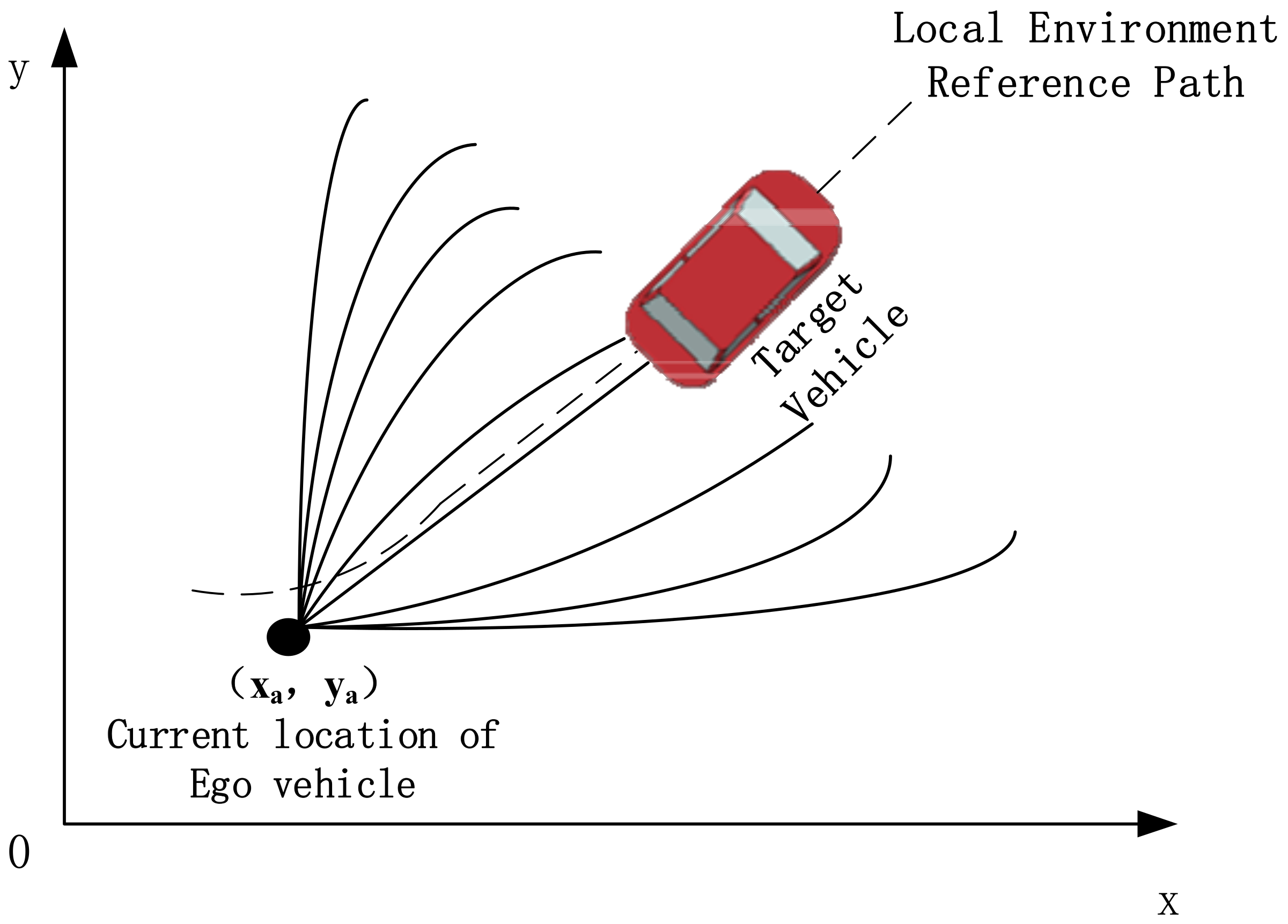
To ensure that the autonomous vehicle achieves higher accuracy in path tracking during lane-changing overtaking maneuvers on highways with dual-lane scenarios and to smooth its motion trajectory, we employ a path-planning algorithm based on fifth-order polynomials within the controller, implemented using Matlab–Simulink. This approach transforms the problem into finding a curve that connects two specified target points (current position and target position) while satisfying requirements such as fixed desired velocity, acceleration, and heading angle at the target points, as illustrated in Figure 4.
Initially, multiple lookahead points along the reference path are identified using various distances. For each lookahead point, candidate target poses with different lateral deviations are generated along its normal direction. The corresponding travel curves form a candidate set. A collision analysis is then performed by comparing vehicle dimensions along each curve with the positions of forward vehicles, retaining only the segments prior to any collision points. Among curves with identical lateral deviations, the longest one is chosen. Finally, a single travel curve that meets both safety and path-tracking requirements is selected as the desired path for the overtaking maneuver.
The construction of a fifth-order polynomial curve allows for the analysis of three state values: displacement, velocity, and acceleration of an object. The fifth-order polynomial takes the following form:
x t = a 0 + a 1 t + a 2 t 2 + a 3 t 3 + a 4 t 4 + a 5 t 5 y t = b 0 + b 1 t + b 2 t 2 + b 3 t 3 + b 4 t 4 + b 5 t 5
where x and y represent the fifth-order polynomials of the vehicle’s lateral and longitudinal positions with respect to time t. By further differentiating them, we obtain the velocity and acceleration curves of the vehicle, denoted as:
x t = a 1 + 2 a 2 t + 3 a 3 t 2 + 4 a 4 t 3 + 5 a 5 t 4 y t = b 1 + 2 b 2 t + 3 b 3 t 2 + 4 b 4 t 3 + 5 b 5 t 4
x t = 2 a 2 + 6 a 3 t + 12 a 4 t 2 + 20 a 5 t 3 y t = 2 b 2 + 6 b 3 t + 12 b 4 t 2 + 20 b 5 t 3
The polynomial curves vary over the time domain. Let t0 be the initial time of the vehicle and t1 be the final time. We solve the position, velocity, and acceleration state equations and represent them in matrix form. Here, X and Y represent the longitudinal and lateral motions, respectively.
X = x 0 , x 0 , x 0 , x 1 , x 1 , x 1 T     = t 0 5 t 0 4 t 0 3 t 0 2 t 0 1 5 t 0 4 4 t 0 3 3 t 0 2 2 t 0 1 0 20 t 0 3 12 t 0 2 6 t 0 2 0 0 t 1 5 t 1 4 t 1 3 t 1 2 t 1 1 5 t 1 4 4 t 1 3 3 t 1 2 2 t 1 1 0 20 t 1 3 12 t 1 2 6 t 1 2 0 0 a 5 a 4 a 3 a 2 a 1 a 0     = T × A
Y = y 0 , y 0 , y 0 , y 1 , y 1 , y 1 T     = t 0 5 t 0 4 t 0 3 t 0 2 t 0 1 5 t 0 4 4 t 0 3 3 t 0 2 2 t 0 1 0 20 t 0 3 12 t 0 2 6 t 0 2 0 0 t 1 5 t 1 4 t 1 3 t 1 2 t 1 1 5 t 1 4 4 t 1 3 3 t 1 2 2 t 1 1 0 20 t 1 3 12 t 1 2 6 t 1 2 0 0 b 5 b 4 b 3 b 2 b 1 b 0     = T × B
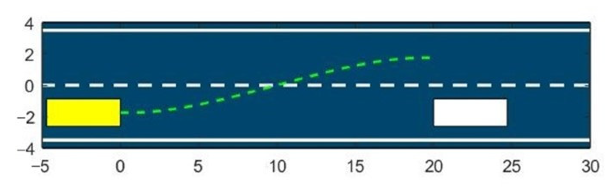
Its implementation in Matlab 2021 is shown in Figure 5:

3.2. MPC-Based Controller Design

This work focuses on the path tracking of autonomous vehicles during overtaking maneuvers in high-speed dual-lane scenarios, necessitating the use of a controller with fast computation speed and excellent real-time performance. Therefore, an MPC approach based on a linear model is adopted. The fundamental concept of MPC is to use existing models, the current system state, and future control inputs to predict the system’s future outputs. This is accomplished by solving a constrained optimization problem to effectively control the front wheels.
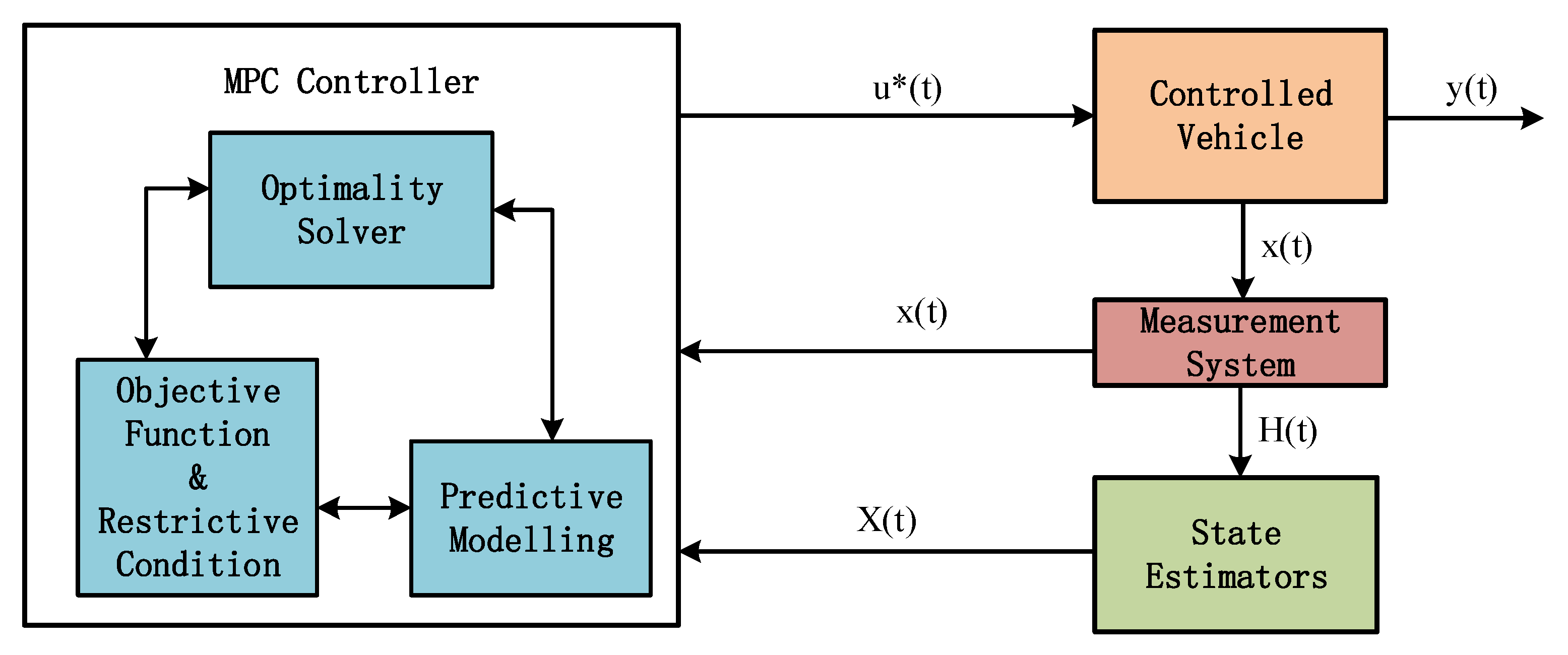
The principal block diagram of MPC is shown in Figure 6, consisting of three modules: the MPC controller, the controlled vehicle, and the state estimator. In this diagram, the MPC controller integrates the predictive model with the objective function and constraints to solve an optimization problem, obtaining the optimal control sequence u*(t) at the current time. This control sequence is then applied to the controlled vehicle, which adjusts to the current control inputs and outputs the optimal front wheel steering angle, y(t). The state variable x(t), which is observed through the measurement system, will be directly input into the MPC module, while the state quantity H(t), which cannot be directly observed or is too costly to measure, is estimated through an estimator. The estimated state quantity X(t) is then fed back into the MPC controller, which performs another optimization to obtain the control sequence for the next time period.
We convert this problem process into a quadratic planning problem, where the model predictive control is based on the model’s prediction of future outputs within a prediction step and solves the quadratic planning problem according to the prediction objective to obtain a future decision series. The discrete system state-space equations are as follows:
X i + 1 = A X i + B u i + C
Within the next N steps
X i + 2 = A X i + 1 + B u i + 1 + C = A 2 X i + A B u i + B u i + 1 + A C + C
X i + 3 = A X i + 2 + B u i + 2 + C = A 3 X i + A 2 B u i + A B u i + 1 + B u i + 2 + A 2 C + A C + C
We define T1, T2, T3 in that case as
T 1 = A X i A 2 X i A 3 X i A N X i
T 2 = B u i A B u i + B u i + 1 A 2 B u i + A B u i + 1 + B u i + 2 A N 1 B u i + A N 2 B u i + 1 + + B u i + N 1
T 3 = C A C + C A 2 C + A C + C A N 1 C + A N 2 + + A C + C
Then, we define Xall as
X a l l = X i + 1 X i + 2 X i + 3 X i + N = T 1 + T 2 + T 3
i.e.,
X a l l = T 1 + T 2 + T 3 = K U + M
where
K = B 0 0 A B B 0 A 2 B A B B 0 0 0 A N 1 B A N 2 B A N 3 B B
U = u i u i + 1 u i + 2 u i + N 1
M = A X i + C A A X i + C + C A A A X i + C + C + C A A A ( A X i + C + C + C + C
Denote the above expression as:
X a l l = K U + M
  • Constructing the objective function
To ensure smooth and accurate tracking of the overtaking path by the vehicle and to avoid encountering unsolvable situations, we adopt the following objective function:
f U = X a l l X r e T Q X a l l X r e + U T R U = K U + M X r e T Q K U + M X r e + U T R U
f U = K U T Q K U + U T R U + 2 ( K U ) M X r e T + a
where a denotes the constant term and X r e denotes the reference system state.
We denote
M 1 = K T Q K + R
M 2 = K T Q M X r e
Thus, the objective function f U can be expressed in quadratic form as
J = 1 2 U T M 1 U + U T M 2

3.3. 2DOF Ideal Model: Ideal-State Variable Calculation

To enhance the vehicle’s handling stability and responsiveness to driver inputs, as well as the flexibility of the control strategy, and ultimately improve the vehicle’s maneuverability, we incorporate a 2-degree-of-freedom (2DOF) ideal model as the path-tracking response model. In this 2DOF ideal model, we consider both the yaw rate and the lateral deviation angle of the center of gravity to better capture the vehicle’s dynamic behavior. These parameters are included in the derivation of the ideal yaw rate formula. Using this model, we compute the desired yaw rate and lateral deviation angle, which are then sent to the 4WS controller as input variables. The controller calculates the required desired yaw rate based on the front wheel steering angle and the vehicle’s motion state, as shown in Equation (31).
W d = v l + K V 2 i δ f i b
where v is the vehicle speed, δ f is the front wheel turning angle, i is the fixed transmission ratio, ib is the variable steering transmission ratio, and K is the vehicle stability parameter, which can be obtained from Equation (32).
K = m l l r c f l f c r
where m is the vehicle mass, l is the wheelbase, l r and l f are the distances from the center of mass to the rear and front axles, and c f and c r are the lateral-deflection stiffnesses of the front and rear wheels, respectively.
When the vehicle performs steering maneuvers such as lane changes, the maximum lateral acceleration achievable by the vehicle is limited by the coefficient of friction µ between the tires and the road surface. Typically, dry, well-maintained asphalt or concrete surfaces have higher coefficients of friction, ranging from 0.7 to 0.85. In the simulated highway environment considered in this paper, where road conditions are relatively good, we assume µ to be 0.85. Therefore, the actual desired yaw rate, constrained by the coefficient of friction of the road surface, can be expressed as:
W d 0.85 μ g v
Since the response of the yaw rate to the front wheel steering angle can be approximated as a first-order time-delay system, the final desired yaw rate can be expressed as:
W d = m i n v l + K V 2 i δ f i b , 0.85 μ g v · s g n δ f · 1 T S + 1
where T S represents the time delay of the first-order time-delay system, v is the vehicle speed, and g is the gravitational acceleration, with specific numerical values as shown in Table 1. Additionally, to ensure the stability of the vehicle at high speeds, the desired lateral deviation angle of the vehicle ( β d ) is set to 0. i.e., β d = 0 .

3.4. 4WS Controller Design

In the field of vehicle dynamic control, establishing a precise and stable control model for the steering system is challenging but crucial for enhancing driving safety and comfort, particularly at high speeds and under complex road conditions. Traditional control methods, such as PID control, often perform poorly when dealing with the nonlinear characteristics of vehicles and external disturbances, posing challenges for improving steering accuracy and stability. To address this issue, we designed a 4WS controller incorporating sliding mode control (SMC) to achieve precise control of the rear-wheel steering angle. In our approach, the SMC-based 4WS controller receives inputs from both the 2DOF ideal model and the vehicle’s actual state, including the front wheel steering angle, the ideal yaw rate, the ideal center-of-gravity sideslip angle, the actual yaw rate, and the actual center-of-gravity sideslip angle, and processes these signals to generate the appropriate rear-wheel steering commands. Sliding mode control is a nonlinear control method renowned for its robustness and excellent control performance. By designing a sliding surface that constrains the system state to move along this surface, SMC effectively mitigates the effects of system parameter variations and external disturbances. This enables rapid adjustment of the system dynamics and ensures robust stable control, thereby improving the stability and accuracy of the vehicle’s steering behavior.
First, we take the errors of the vehicle’s centroid sideslip angle and yaw rate, β r β d and w r w d as the sliding surface for the sliding mode control, which can be expressed as:
S = e + λ 0 1 e d t
where
e = λ 1 β r β d + λ 2 w r w d
Taking the derivative of the sliding surface, we obtain:
S ˙ = e ˙ + λ e
To suppress the chattering of the sliding mode structure and ensure system stability, while allowing the system to quickly approach the sliding surface, we design the approach rate of the sliding surface as:
S r ˙ = ε   s g n S k r S
where ε and k r are diagonal gain matrices. Therefore, combining the approach rate of the sliding surface, Equation (30) can be expressed as:
S ˙ = e ˙ + λ e = S r ˙ = ε   s g n S k r S
Hence,
λ 1 β r ˙ β d ˙ + λ 2 w r ˙ w d ˙ + λ e = ε   s g n S k r S
Combining with the dynamic differential equations from Equations (12)–(14) and (35), we define:
f 1 = c f + c r m v β r + a c f b c r m v 2 1 w r c f m v δ f
f 2 = a c f b c r I z β r + a 2 c f + b 2 c r I z v w r a c f I z δ f
g 1 = c f m v
g 2 = b c r I z
Thus, Equation (33) can be expressed as:
λ 1 β r ˙ f 1 g 1 δ r + λ 2 w r ˙ f 2 g 2 δ r + λ = ε   s g n S k r S
Therefore, the rear-wheel steering angle δ r can be solved as:
δ r = λ 1 β r ˙ f 1 + λ 2 w r ˙ f 2 + λ e + ε   s g n S + k r S λ 1 g 1 + λ 2 g 2

4. Performance Validation

4.1. Experimental Environment and Parameters

We established a co-simulation platform using Simulink and CarSim. The selected ego vehicle is an Exotic Car, Mid-Engine: MT with the following configuration: a sprung mass of 1360 kg, an animator height of 1158 mm, and an animator width of 2064 mm. The simulations were conducted under high-speed conditions, with vehicle speeds set at 108 km/h on a road surface with a friction coefficient of 0.85. The double-lane-change maneuver, a typical scenario for high-speed overtaking and obstacle avoidance, was used. Therefore, we adopted the ISO standard double-lane-change maneuver as the reference road input for this study. The closed-loop control strategy system and the controller designed in this paper were verified using the road environment built with the simulation software CarSim 2020. The vehicle configuration parameters for the hybrid control strategy designed in this study are shown in Table 1.

4.2. Comparative Analysis of Single MPC and MPC-4WS Hybrid Controllers

In Table 2, we provide a side-by-side comparison of the single MPC controller and the proposed MPC-4WS hybrid controller. As shown, the single MPC controller primarily focuses on achieving path-tracking accuracy through front-wheel steering control, whereas the MPC-4WS hybrid controller enhances performance by incorporating rear-wheel steering. This integration not only improves path tracking but also significantly boosts vehicle stability, particularly under high-speed and dynamically changing conditions. The MPC-4WS approach incorporates additional constraints and refined dynamic models, resulting in faster convergence and greater robustness against nonlinear uncertainties and disturbances. Although this comes with a slight increase in computational complexity, the overall performance benefits—demonstrated through metrics such as maximum lateral error, yaw rate deviation, and convergence time—clearly illustrate the advantages of our proposed method over the traditional single MPC approach.

4.3. Simulation Result and Analysis

We evaluated the stability of the 4WS control system by tracking indicators such as yaw rate, centroid sideslip angle, and lateral acceleration curves. The path-tracking accuracy and stability were assessed by examining the overall XY driving path-tracking curve in Section 5. The simulation results are shown in Figure 7, Figure 8 and Figure 9.
In this study, we conducted a comparative analysis of two evaluation indicators—centroid sideslip angle and yaw rate—under a single MPC controller and our MPC-4WS hybrid controller to assess the effectiveness of the control system on vehicle lateral stability and steering control. The experimental results output by Simulink, as shown in Figure 7, indicate that within 40 s of simulation, our MPC-4WS hybrid controller outperformed the single MPC controller in terms of centroid sideslip angle and yaw rate curves, demonstrating superior control performance and stability. Except for the 5th and 20th seconds, when the vehicle had just completed a lane change and needed to process new lane road environment information and behavior prediction, resulting in fluctuations in the centroid sideslip angle and yaw rate curves, the maximum fluctuation values were ±7° and ±0.6 rad/s, respectively, which are well within the system’s designed safety range. Research by Bosch shows that on dry asphalt roads with good adhesion, the safe range for stable driving is a centroid sideslip angle of ±12° and a yaw rate between 5 and 10 rad/s. At other times, the vehicle’s centroid sideslip angle and yaw rate remained nearly at zero, indicating that the control system effectively suppressed lateral and yaw motions. Moreover, the output curves reveal that except during lane changes, the vehicle’s centroid sideslip angle and yaw rate were scarcely affected by other factors, maintaining extremely low levels. This indicates that the path-control system also exhibits good stability and anti-interference capability.
Additionally, we analyzed the vehicle’s lateral acceleration, as shown in Figure 8, to evaluate the control system’s effectiveness in managing the vehicle’s lateral motion. From the lateral acceleration versus time curve, it can be seen that during the 40 s of experimental simulation, the vehicle exhibited significant lateral acceleration fluctuations only at the 5th and 20th seconds. These fluctuations occurred because the vehicle had just completed lane changes and needed to process new lane road environment information and behavior predictions. For the rest of the time, the lateral acceleration remained nearly zero, indicating that the vehicle could smoothly complete the double-lane-change maneuver.
Notably, during key moments in the simulation when lane changes were required, the lateral acceleration curve showed significant fluctuations. However, even during these moments, the vehicle’s maximum lateral acceleration did not exceed 0.05 m/s², which is well below the system’s design limit. According to Europe’s ECE R79 regulations, the maximum lateral acceleration during lane keeping should not exceed 3 m/s². This demonstrates that the path-tracking system can effectively control the vehicle’s lateral motion, maintaining it within a safe range.
In addition, Figure 9 compares the longitudinal velocity profiles of the single MPC controller, the proposed MPC-4WS hybrid controller, and the reference. Overall, both controllers track the reference velocity with minimal deviation. However, the MPC-4WS method has a slightly faster acceleration phase and is able to converge back to the target velocity more smoothly after reaching the peak. This suggests that the hybrid MPC-4WS controller not only facilitates lateral stability but also contributes to more responsive longitudinal control, especially during high-speed maneuvers. In contrast, the single MPC method suffers from a small delay in matching the reference value and a slightly higher steady-state error. As a result, the MPC-4WS hybrid controller excels in maintaining longitudinal speed accuracy and stability under demanding driving conditions.

5. Discussion

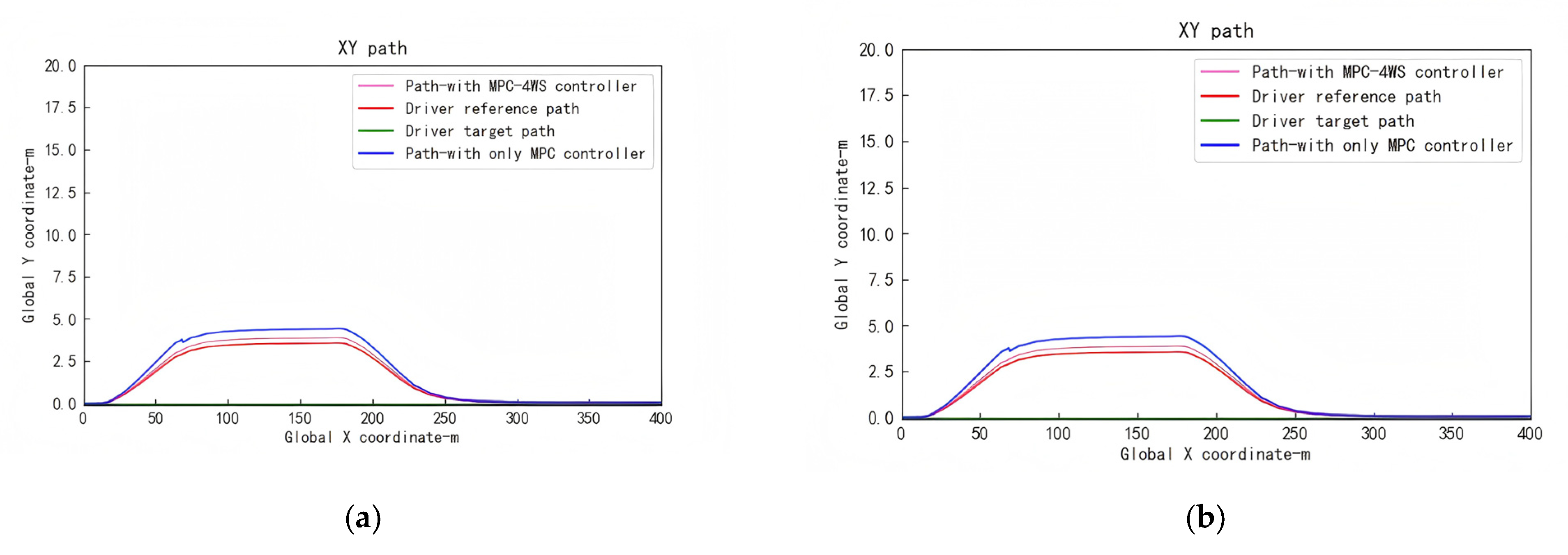
To evaluate the accuracy and stability of the proposed control strategy’s path-tracking system, we compared the relative proximity of the vehicle’s XY driving path curves to the reference path over a 400 m distance using both the MPC controller and the MPC-4WS hybrid controller. The experimental results, shown in Figure 10, indicate that the control and path-tracking performance of the designed MPC-4WS hybrid controller are superior to those of the standalone MPC controller.
Comparison with the reference path reveals that the driving path of the hybrid MPC-4WS controller significantly outperforms that of the single MPC controller throughout the entire 400 m driving distance from the start of overtaking to switching to the left lane and then returning to the original lane. Specifically, in the overtaking phase, the traveling path error of the MPC-4WS controller is reduced by 65.88%, and the maximum error with respect to the reference path is reduced by about 0.553 m from 0.8633 m of the single MPC controller to 0.3102 m, while the path curve is smoother, reflecting its superior path-tracking performance. In addition, the actual traveling path of the vehicle is highly consistent with the ideal reference path, almost perfectly reproducing the preset path.
Further analysis of the shape and trend of the path curves shows that the vehicle gradually approaches the reference path during the driving process after completing the overtaking, and the deviation gradually decreases and finally overlaps with the target path completely. This indicates that the designed path-tracking system possesses excellent stability and is able to consistently approach the target path during the driving process, avoiding significant deviations or jerks.
In summary, the experimental results fully demonstrate the significant advantages of the proposed MPC-4WS hybrid control strategy in terms of path-tracking accuracy and stability, which effectively improves the maneuverability and safety of self-driving vehicles in high-speed scenarios.

6. Conclusions

This paper focuses on the overtaking problem of autonomous vehicles in high-speed conditions. It investigates a fusion control strategy that combines Model Predictive Control (MPC) and Four-Wheel Steering (4WS) to enable autonomous vehicles to smoothly perform lane-changing maneuvers at high speeds while ensuring vehicle maneuverability, stability, and good path-tracking performance.
Considering the need for a fast and real-time controller for path tracking during overtaking maneuvers of autonomous vehicles in high-speed dual-lane scenarios, this study adopts an MPC-based linear model predictive controller. The problem is formulated as a quadratic programming problem to determine the front-wheel steering angle and future decision behavior of the vehicle. To ensure accurate path tracking and smooth vehicle motion, a fifth-degree polynomial path-planning algorithm is incorporated into the controller and implemented using Matlab–Simulink.
To accurately capture the vehicle’s dynamic behavior, improve responsiveness to driver inputs, enhance control flexibility, and achieve good maneuvering stability, this work proposes a 2DOF (degrees of freedom) ideal model as the path-tracking response model. The model considers the yaw rate and center of gravity lateral displacement and calculates the ideal yaw rate and ideal lateral displacement using derived formulas. These values are then fed as inputs to the 4WS controller responsible for rear-wheel control. This approach ensures a good path-tracking response of the vehicle in high-speed dual-lane scenarios.
To address issues of insufficient steering precision and stability deterioration during high-speed driving and complex road conditions, this paper introduces sliding mode control to establish a precise and stable control model for accurate control of the rear-wheel steering angle. A sliding surface is designed to force the system state to move on this surface, effectively overcoming the effects of system parameter variations and external disturbances, achieving fast dynamic adjustment and a robust, stable control of the system.
The joint simulation results of Carsim–Simulink indicate that the closed-loop control strategy system constructed in this paper can effectively suppress the lateral and yaw motions of the vehicle in high-speed dual-lane scenarios. It exhibits good stability and disturbance rejection capabilities, keeps the vehicle moving within a safe range, and achieves high-precision path tracking, thereby ensuring the maneuverability and safety of autonomous vehicles.
In summary, this paper proposes a hybrid control strategy based on MPC and 4WS, incorporating a 2DOF ideal model that considers yaw rate and center of gravity lateral displacement as the response model. The aim is to enable autonomous vehicles to achieve good path-tracking performance while ensuring vehicle maneuverability, safety, and stability in high-speed dual-lane scenarios.
Future research will focus on optimizing control strategy parameters, integrating alternative predictive control algorithms, and enhancing environmental perception (e.g., with higher-precision sensors) to reduce performance fluctuations during lane changes. Additional studies will address improved steering stability and overall path-tracking performance in complex, dynamic environments. Moreover, we will explore advanced control strategies such as prescribed performance control (PPC), which pre-defines error convergence trajectories and performance indices to impose strict system constraints while enhancing accuracy and responsiveness. Compared to the current MPC-4WS hybrid approach, PPC may offer superior robustness against nonlinear uncertainties and dynamic changes, and future work will evaluate its integration with our method for high-performance path tracking under challenging conditions. In addition, future research may also develop adaptive control strategies that dynamically adjust key parameters—such as the MPC-weighting matrices—based on individual driver-overtaking styles and preferred speed ranges, thereby further enhancing system adaptability and performance across diverse driving behaviors.

Author Contributions

Conceptualization, L.L.; methodology, G.S.; software, G.S.; validation, S.C.; investigation, C.W.; resources, L.L.; data curation, G.S.; writing—original draft preparation, G.S. and L.L.; writing—review and editing, L.L., S.C., C.W. and J.Z.; visualization, S.C.; funding acquisition, L.L. and J.Z. All authors have read and agreed to the published version of the manuscript.

Funding

This research was funded by the projects of the National Natural Science Foundation of China (62376059), in part by projects of Fujian Provincial Department of Science and Technology (2021Y4019, 2020D002, 2020L3014), projects of Fujian Provincial Department of Finance (GY-Z230007), and, in part, by the project of Fujian University of Technology (GY-Z160064).

Data Availability Statement

Data are contained within the article.

Conflicts of Interest

The authors declare no conflicts of interest.

References

  1. Mortazavizadeh, S.A.; Ghaderi, A.; Ebrahimi, M.; Hajian, M. Recent developments in the vehicle steer-by-wire system. IEEE Trans. Transp. Electrif. 2020, 6, 1226. [Google Scholar] [CrossRef]
  2. Wangzhong, Z.; Han, Z.; Songchun, Z.; Kunhao, X.; Chang, L. Overview of vehicle steer-by- wire system control technologies. J. Automot. Saf. Energy 2021, 12, 18. [Google Scholar]
  3. Arifin, B.; Suprapto, B.Y.; Prasetyowati, S.A.D.; Nawawi, Z. The lateral control of autonomous vehicles: A review. In Proceedings of the 2019 International Conference on Electrical Engineering and Computer Science (ICECOS), Batam, Indonesia, 2–3 October 2019; p. 277. [Google Scholar]
  4. Li, D.; Zhao, D.; Zhang, Q.; Chen, Y. Reinforcement learning and deep learning based lateral control for autonomous driving [application notes]. IEEE Comput. Intell. Mag. 2019, 14, 83. [Google Scholar] [CrossRef]
  5. Li, S.E.; Chen, H.; Li, R.; Liu, Z.; Wang, Z.; Xin, Z. Predictive lateral control to stabilise highly automated vehicles at tire-road friction limits. Veh. Syst. Dyn. 2020, 58, 768–786. [Google Scholar] [CrossRef]
  6. Gao, H.; Kan, Z.; Li, K. Robust lateral trajectory following control of unmanned vehicle based on model predictive control. IEEE/ASME Trans. Mechatron. 2021, 27, 1278–1287. [Google Scholar] [CrossRef]
  7. Ahmed, A.A.; Jomah, O.S.M. Vehicle yaw rate control for lane change maneuver using fuzzy PID controller and neural network controller. In Proceedings of the 2020 IEEE 2nd International Conference on Electronics, Control, Optimization and Computer Science (ICECOCS), Kenitra, Morocco, 2–3 December 2020; IEEE: New York, NY, USA; pp. 1–6. [Google Scholar]
  8. Zhang, C.; Hu, J.; Qiu, J.; Yang, W.; Sun, H.; Chen, Q. A novel fuzzy observer-based steering control approach for path tracking in autonomous vehicles. IEEE Trans. Fuzzy Syst. 2018, 27, 278. [Google Scholar] [CrossRef]
  9. Hu, C.; Chen, Y.; Wang, J. Fuzzy observer-based transitional path-tracking control for autonomous vehicles. IEEE Trans. Intell. Transp. Syst. 2020, 22, 3078–3088. [Google Scholar] [CrossRef]
  10. Lian, Z.; Shi, P.; Lim, C.C.; Yuan, X. Fuzzy-model-based lateral control for networked autonomous vehicle systems under hybrid cyber-attacks. IEEE Trans. Cybern. 2022, 53, 2600. [Google Scholar] [CrossRef]
  11. Mohammadzadeh, A.; Taghavifar, H. A robust fuzzy control approach for path-following control of autonomous vehicles. Soft Comput. 2020, 24, 3223. [Google Scholar] [CrossRef]
  12. Yang, T.; Bai, Z.; Li, Z.; Feng, N.; Chen, L. Intelligent vehicle lateral control method based on feedforward+ predictive LQR algorithm. Actuators 2021, 10, 228. [Google Scholar] [CrossRef]
  13. Wei, S.; Zou, Y.; Zhang, X.; Zhang, T.; Li, X. An integrated longitudinal and lateral vehicle following control system with radar and vehicle-to-vehicle communication. IEEE Trans. Veh. Technol. 2019, 68, 1116. [Google Scholar] [CrossRef]
  14. Kati, M.S.; Fredriksson, J.; Jacobson, B.; Laine, L. A feedback-feed-forward steering control strategy for improving lateral dynamics stability of an A-double vehicle at high speeds. Veh. Syst. Dyn. 2022, 60, 3955. [Google Scholar] [CrossRef]
  15. Zhang, J.; Wang, H.; Ma, M.; Yu, M.; Yazdani, A.; Chen, L. Active front steering-based electronic stability control for steer-by-wire vehicles via terminal sliding mode and extreme learning machine. IEEE Trans. Veh. Technol. 2020, 69, 14713–14726. [Google Scholar] [CrossRef]
  16. Hang, P.; Xia, X.; Chen, X. Handling stability advancement with 4WS and DYC coordinated control: A gain-scheduled robust control approach. IEEE Trans. Veh. Technol. 2021, 70, 3164. [Google Scholar] [CrossRef]
  17. Laurense, V.A.; Gerdes, J.C. Long-horizon vehicle motion planning and control through serially cascaded model complexity. IEEE Trans. Control. Syst. Technol. 2021, 30, 166–179. [Google Scholar] [CrossRef]
  18. Baskaran, A.; Talebpour, A.; Bhattacharyya, S. End-to-end drive by-wire PID lateral control of an autonomous vehicle. In Proceedings of the Future Technologies Conference, San Francisco, CA, USA, 24–25 October 2019; p. 365. [Google Scholar]
  19. Tan, X.; Liu, D.; Xiong, H. Optimal control method of path tracking for four-wheel steering vehicles. Actuators 2022, 11, 61. [Google Scholar] [CrossRef]
  20. Yu, S.; Wang, J.; Wang, Y.; Chen, H. Disturbance observerbased control for four-wheel steering vehicles with model reference. IEEE/CAA J. Autom. Sin. 2016, 5, 1121. [Google Scholar] [CrossRef]
  21. Spielberg, N.A.; Brown, M.; Kapania, N.R.; Kegelman, J.C.; Gerdes, J.C. Neural network vehicle models for high-performance automated driving. Sci. Robot. 2019, 4, eaaw1975. [Google Scholar] [CrossRef]
  22. Ge, L.; Zhao, Y.; Ma, F.; Guo, K. Towards longitudinal and lateral coupling control of autonomous vehicles using offset free MPC. Control. Eng. Pract. 2022, 121, 105074. [Google Scholar] [CrossRef]
  23. Rosolia, U.; Borrelli, F. Learning how to autonomously race a car: A predictive control approach. IEEE Trans. Control. Syst. Technol. 2019, 28, 2713–2719. [Google Scholar] [CrossRef]
  24. Cheng, S.; Li, L.; Guo, H.Q.; Chen, Z.G.; Song, P. Longitudinal collision avoidance and lateral stability adaptive control system based on MPC of autonomous vehicles. IEEE Trans. Intell. Transp. Syst. 2019, 21, 2376. [Google Scholar] [CrossRef]
  25. Chu, D.; Li, H.; Zhao, C.; Zhou, T. Trajectory tracking of autonomous vehicle based on model predictive control with PID feedback. IEEE Trans. Intell. Transp. Syst. 2022, 24, 2239. [Google Scholar] [CrossRef]
  26. Dixit, S.; Montanaro, U.; Dianati, M.; Oxtoby, D.; Mizutani, T.; Mouzakitis, A.; Fallah, S. Trajectory planning for au- tonomous high-speed overtaking in structured environments using robust MPC. IEEE Trans. Intell. Transp. Syst. 2019, 21, 2310. [Google Scholar] [CrossRef]
  27. Guo, N.; Lenzo, B.; Zhang, X.; Zou, Y.; Zhai, R.; Zhang, T. A real-time nonlinear model predictive controller for yaw motion optimization of distributed drive electric vehicles. IEEE Trans. Veh. Technol. 2020, 69, 4935. [Google Scholar] [CrossRef]
  28. Wei, M.; Zheng, L.; Li, H.; Cheng, H. Adaptive Neural Network-based Model Path-Following Contouring Control for Quadrotor Under Diversely Uncertain Disturbances. IEEE Robot. Autom. Lett. 2024, 9, 3751–3758. [Google Scholar] [CrossRef]
  29. Cheng, S.; Hu, B.B.; Wei, H.L.; Li, L.; Lv, C. Deep learning-based hybrid dynamic modeling and improved handling stability assessment for autonomous vehicles at driving limits. IEEE Trans. Veh. Technol. 2024, 1–13. [Google Scholar] [CrossRef]
  30. Tristano, M.; Lenzo, B.; Xu, X.; Forrier, B.; D’hondt, T.; Risaliti, E.; Wilhelm, E. Hardware-in-the-loop real-time implementation of a vehicle stability control through individual wheel torques. IEEE Trans. Veh. Technol. 2024, 73, 4683–4693. [Google Scholar] [CrossRef]
  31. Bu, X.; Luo, R.; Lv, M.; Lei, H. Adaptive fuzzy safety control of hypersonic flight vehicles pursuing adaptable prescribed behaviors: A sensing and adjustment mechanism. IEEE Trans. Fuzzy Syst. 2024, 32, 7050–7062. [Google Scholar] [CrossRef]
  32. Bu, X.; Lv, M.; Liu, Z. Intelligent safety flight control with variable prescribed performance. IEEE Trans. Aerosp. Electron. Syst. 2023, 60, 2050–2060. [Google Scholar] [CrossRef]
  33. Bu, X.; Park, J.H.; Lei, H. Discrete-time neural control with flexible prescribed performance for constrained systems with fragility relaxation. IEEE Trans. Autom. Sci. Eng. 2024, 22, 2386–2394. [Google Scholar] [CrossRef]
Figure 1. Schematic diagram of autopilot vehicle trajectory in double-shift line condition.
Electronics 14 01133 g001
Figure 2. 2-degree-of-freedom vehicle dynamics model.
Electronics 14 01133 g002
Figure 3. General schematic of the overall control strategy with MPC and 4WS controllers with ideal models.
Electronics 14 01133 g003
Figure 4. Path planning based on fifth-degree polynomials.
Electronics 14 01133 g004
Figure 5. Vehicle lane changing based on fifth-degree polynomial path-planning algorithm.
Electronics 14 01133 g005
Figure 6. Block diagram of model predictive control principle.
Electronics 14 01133 g006
Figure 7. Mass side deflection angle and transverse pendulum angular velocity curves for two speed conditions. (a) Lateral deflection of the center of mass at 108 km/h; (b) lateral deflection of the center of mass at a speed of 90 km/h; (c) angular velocity of the pendulum at a speed of 108 km/h; (d) angular velocity of the pendulum at a speed of 90 km/h.
Electronics 14 01133 g007
Figure 8. Vehicle lateral acceleration curves for two speed conditions. (a) Lateral acceleration at a speed of 108 km/h; (b) lateral acceleration at a speed of 90 km/h.
Electronics 14 01133 g008
Figure 9. Vehicle longitudinal speed profile.
Electronics 14 01133 g009
Figure 10. Vehicle’s XY driving path curves over 400 m under two speed conditions. (a) Vehicle’s XY driving-path curve over 400 m at a speed of 108 km/h; (b) vehicle’s XY driving-path curve over 400 m at a speed of 90 km/h.
Electronics 14 01133 g010
Table 1. Vehicle configuration parameters.
SymbolParameterValueUnit
mVehicle mass1517.4kg
CfFront tire cornering stiffness8013N/rad
CrRear tire cornering stiffness7791N/rad
LfWheelbases (forward)1.455m
LrWheelbases (backward)1.195m
Izmoment of inertia1065.2kg·m2
VSpeed108/90km/h
ggravitational acceleration9.8m/s2
uPavement adhesion
coefficient
0.85
Table 2. Key differences between MPC and MPC-4WS.
AspectSingle MPCMPC-4WS
Control FocusFront-wheel steering onlyIntegrated front- and rear-wheel steering
Dynamic ResponseAdequate for moderate driving conditionsEnhanced stability and
responsiveness at high speeds
RobustnessLimited against nonlinear
disturbances
Improved handling of uncertainties
Overall
Performance
Satisfactory path trackingSuperior path tracking and vehicle stability
Disclaimer/Publisher’s Note: The statements, opinions and data contained in all publications are solely those of the individual author(s) and contributor(s) and not of MDPI and/or the editor(s). MDPI and/or the editor(s) disclaim responsibility for any injury to people or property resulting from any ideas, methods, instructions or products referred to in the content.

