Article

Picosecond-Level Synchronization over Optical Free Space Link Using White Rabbit

by
Peng Zhang
1,
Dong Hou
1,*,
Ke Liu
1,
Wenjian Zhou
1,
Minghong Li
1 and
Lujun Fang
2
1
School of Automation Engineering, University of Electronic Science and Technology of China, Chengdu 611731, China
2
Science and Technology on Communication Security Laboratory, Institute of Southwestern Communication, Chengdu 610041, China
*
Author to whom correspondence should be addressed.
Electronics 2025, 14(5), 970; https://doi.org/10.3390/electronics14050970
Submission received: 13 January 2025 / Revised: 17 February 2025 / Accepted: 24 February 2025 / Published: 28 February 2025
(This article belongs to the Special Issue Applications of MEMS and QCM in Smart Sensor Systems)

Abstract

:
White Rabbit (WR) time synchronization has an accuracy up to a sub-nanosecond level. However, the current application scenario of WR is limited to wired transmission links. In this paper, we have proposed a time synchronization technique over a free space link using WR. In the WR-based free space synchronization scheme, we replace the original WDM (Wavelength Division Multiplexing) with single-wavelength transmission to reduce the asymmetry of the path and design a high-power optical transceiver module to improve the transmission power. With the scheme, a free space synchronization experiment with a transmission distance of 50 m is conducted. The experimental results show that the RMS (root mean square) time drift of this free space synchronization system is 20.5 ps over a 24 h period, and the TDEV (Time Deviation) of the time synchronization is 14.3 ps at 1 s and 3.9 ps at 20,000 s. The experiment proves that it will be convenient to complete the free space time synchronization network between clock sites with the proposed technique in the future application of complex environments.

1. Introduction

In the field of communication, the core prerequisite of a digital communication system is the ability to accomplish time synchronization. The current 5G technology relies on GPS receivers to complete time synchronization, and its network time synchronization accuracy is generally within ±100 ns; for the future 6G technology, the time synchronization accuracy should reach sub-nanoseconds or even higher. Nowadays, the highest synchronization accuracy and the longest synchronization distance in the field of time synchronization is the White Rabbit precision time protocol (White Rabbit, WR) proposed by the European Institute of Particle Physics (CERN) [1,2].
In 2012, CERN, to verify the feasibility and synchronization accuracy of using GPS for time synchronization in the CNGS project, for the first time used a link system based on the WR protocol, which is capable of providing nanosecond synchronization accuracy over long distances (more than 16 km). The measurement accuracy of the deployed system was 0.517 ns, and its calculated MTIE value was below 1.05 ns [3]. In 2016, the Finnish MIKES laboratory performed time transfer experiments between Espoo and Kajaani in the dark channel of the Finnish Universities and Research Network (FUNET) with a link length of 950 km, and the time synchronization accuracy of the whole system is around ± 2 ns, and the stability achieved can be up to 20 ps at 1000 s [4]. In the same year, the NIKHEF Institute for High Energy Physics in the Netherlands conducted 2 × 137 km WR time–frequency synchronization link transmission experiments with bi-directional fiber wavelengths of 1470/1490 nm, respectively, and the time synchronization accuracy of the test system is above 8 ns, and the kilosecond-level stability can reach 10 ps [4]. In 2019, the concept of WR-PTP was updated in the new IEEE1588 standard; the WR Precision Time Synchronization Protocol effectively solves the problem of distributed, large-scale time synchronization and can achieve a fairly high time synchronization accuracy, and its equipment overhead is much smaller compared to GPS [5,6,7].
The WR protocol is based on wired transmission design technology. With the expansion of human resources to explore other regions, in valleys, the ocean, and other areas, due to the inability to lay wired cable, wireless transmission is often required to complete high-precision time synchronization [8,9]. However, in most existing high-precision wireless synchronization technology, such as microwave, satellite, FSO, etc., there is point-to-point design, the realization of the cost is high, and it cannot be configured on a large scale. Therefore, utilizing the WR protocol for wireless synchronization in free space can effectively achieve high-precision time synchronization of field equipment networks [10,11,12].
In this paper, an optical free space time synchronization technique based on WR is proposed. In this technique, a high-power SFP+ module is designed, combined with a circulator to isolate the RX end from the TX end, to realize time synchronization between two free space sites. With this technique, we complete the free space WR time synchronization experiment with a transmission distance of 50 m. The time synchronization experimental results show that the TDEV is 14.3 ps at 1 s and 3.9 ps at 20,000 s.

2. Principle of WR Time Synchronization

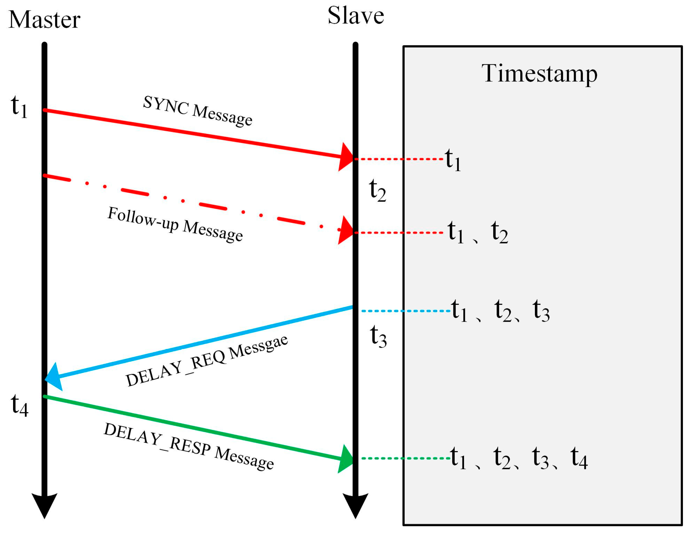
2.1. Precision Time Protocol

In the beginning, the clock with the highest precision will be set as the master clock and the others as slave clocks. When the PTP protocol determines the master and slave clocks in the synchronization network, the respective corresponding master and slave nodes can start to continuously exchange messages with local timestamp information, and when assuming the symmetry of the transmission link, the timestamps obtained from the messages can be used to calculate the link transmission delay and the intrinsic clock deviation, and the typical PTP message exchange process is shown in Figure 1. This approach can also be considered as a request–response mechanism based on a ring loop [13].
The PTP protocol interacts with messages once per second, and its messages are divided into two types, as shown in Figure 1; the first is event messages, including SYNC and DELAY_REQ, which are used to measure offsets and delays, and the second is general messages, including Follow-up and DELAY_RESP, which are used to recognize each other’s nodes in the PTP network structure or to establish the clock hierarchy and exchange setup parameters [14].
After the synchronization process begins, the master node will periodically send synchronization messages to the slave node and record the sending time t1, and the slave node will record the receiving time t2 of the synchronization message. If the PTP protocol is in single-step mode, t1 will be embedded in the synchronization message and sent together to the slave node; if the PTP protocol is in two-sequence mode, the following message will be carried by the timestamp t1 and sent to the slave node alone. After receiving t1 and t2, the slave node will send a delayed request message and record the time of sending t3; the master node will record the time of receiving the message t4, and send the timestamp t4 back to the slave node through the delayed response message; after two request–response circuits, the slave node will receive four timestamps, t1, t2, t3, t4 [15].
Assuming that there exists a time deviation of offsetMS between the master clock and the slave clock at a certain moment (here, it is assumed that the master clock is ahead of the slave clock; otherwise, offsetMS is less than 0), and the link delay of the synchronization message from the master node to the slave node is delayMS, then we have:
d e l a y M S = t 2 t 1 + o f f s e t M S .
Assuming that when the next moment delay request message is sent from the slave node to the master node, the time deviation between the slave clock and the master clock exists as offsetSM, and the link delay of the message transmission from the slave node to the master node is delaySM, then we have:
d e l a y S M = t 4 t 3 o f f s e t S M .
It is further assumed that the deviation of the master and slave clocks does not change during a time synchronization loop, so we have:
o f f e s t = o f f s e t M S = o f f s e t S M ,
and the delay of the round-trip path of the message is equal, then we have:
d e l a y M S = d e l a y S M .
It follows from the above equation that:
d e l a y = d e l a y M S = d e l a y S M = t 2 t 1 + o f f s e t M S = t 4 t 3 o f f s e t S M ,
d e l a y = t 2 t 1 + t 4 t 3 2 ,
o f f e s t = t 1 t 2 + t 4 t 3 2 .
With the above formula, the slave node will be able to use the obtained timestamps t1, t2, t3, and t4 to calculate the master–slave time deviation, thus synchronizing the slave node’s oscillator to the master node’s system clock and completing the coarse measurement of the transmission link latency.

2.2. Digital Dual Mixer Time Difference (DDMTD)

In the WR time synchronization protocol due to the PTP protocol timestamp resolution is limited by the Gigabit Ethernet network rate, the theoretical optimum can only reach one clock cycle, and synchronization accuracy and resolution struggle to reach the sub-nanosecond level. The DDMTD can measure the phase difference, which is smaller than the timestamp resolution. After the PTP protocol completes the coarse measurement of time deviation between master and slave nodes, it can be used as a phase difference fine measurement method to measure the phase difference between the master node clock signal recovered by the CDR circuit from the slave node and the local oscillator clock signal. This improves the measurement accuracy and resolution of the phase delay introduced during the transmission of the master–slave link in the WR time synchronization protocol. Figure 2 shows the schematic diagram of the digital dual-mixing phase discriminator [16].
Based on the local input clock, fCLKA, the auxiliary phase-locked loop generates an auxiliary sampling clock, fdmtd, which is used for the D flip-flop to realize sampling amplification of the input signal. The fdmtd is defined as:
f d m t d = N N + 1 f C L K A ,
where N is an integer defining the input clock division ratio; N + 1 is the feedback clock division ratio.
Equation (8) shows that the auxiliary sampling clock fdmtd gets closer and closer to the local input clock fCLKA as N increases, and the frequency difference between fCLKA and fdmtd is defined as the beat frequency fbeat, which is the fundamental frequency of the output signal of the D flip-flop.
The phase difference between two input signals fCLKA and fCLKB can be defined as:
t = t b e a t f b e a t f C L K A = t b e a t N + 1 ,
t b e a t is the amplified phase difference between the two D flip-flop output signals measured by the low-frequency counter.
This will use the D flip-flop to ensure that the original signal phase proportionality to the case of the completion of the signal overall sampling amplification, to achieve the time multiplier effect, at this time with a low-frequency counter can measure the phase difference between the two clock signals of the same frequency with high precision. The DDMTD circuit waveform is as shown in Figure 3 [17].
When the frequency of the low-frequency interval counter in DDMTD is set to the same frequency as the auxiliary clock signal fdmtd, the measurement phase difference resolving power that can be achieved by DDMTD is:
t D M T D = f b e a t f C L K A · f C L K B = 1 ( N + 1 ) · f C L K B .
In the WR time synchronization protocol, the purpose of DDMTD is to improve the timestamp resolution of the PTP. In the PTP, the recovery clock frequency of the Gigabit Ethernet link is 125 MHz. For an input frequency of 125 MHz, when N is set to 8192, the auxiliary clock generated by the auxiliary phase-locked loop is 124.985 MHz. Then, the fundamental frequency fbeat is 15 kHz, and DDMTD will obtain a phase-difference resolution of 0.976 ps. This directly improves the minimum 8 ns timestamp resolution of the PTP protocol to the picosecond level [18,19].

2.3. WR Synchronization in Free Space

In the principle of two-way time transfer, it is assumed that the path of signal transmission is completely symmetric; however, there is no completely symmetric path in the actual transmission, so it is necessary to study the asymmetry of the path. The WR protocol is based on optical fiber wired transmission technology. The optical fiber using the transmission module is SFP, and it generally uses WDM to complete the bidirectional time transmission [20,21,22]. WDM allows different wavelengths of light transmission in the same transmission path, to ensure that the optical range is the same, but the wavelengths of the back and forth are different, and the existence of chromatic dispersion leads to differences in the transmission time, as well as the introduction of additional asymmetry. The traditional WR protocol, to solve this problem, incorporates a compensation module, which compensates for the asymmetry by specifying the transmission wavelength used by the WDM, establishing a compensation model, and measuring the transmission distance by loopback before synchronization. However, in practice, the device process and environmental parameter changes can lead to some misalignment of this compensation model. In addition, the transmission attenuation of optical signals in free space is much higher than that of optical fibers, and it is difficult for traditional SFP modules to support long-distance transmission in free space [23,24,25].
Therefore, in this paper, the optical transmitter–receiver module is improved in the free space WR time synchronization system. We have abandoned WDM; the same wavelength of light is used for both transmission and reception of this module. To ensure that the signals in the sending and receiving paths are not crosstalked, a circulator component is added to the backstage to ensure a high degree of isolation between the sending and receiving signals. This system greatly reduces the asymmetry of the path. Meanwhile, the module selects a high-power laser with an output power of up to 3 dBm, which is larger than the traditional SFP and can support long-distance free space transmission. Its main parameters can be seen in Table 1 and Table 2, and the specific design refers to Section 3.1.

3. Scheme and Implementation of WR-Based Free Space Synchronization

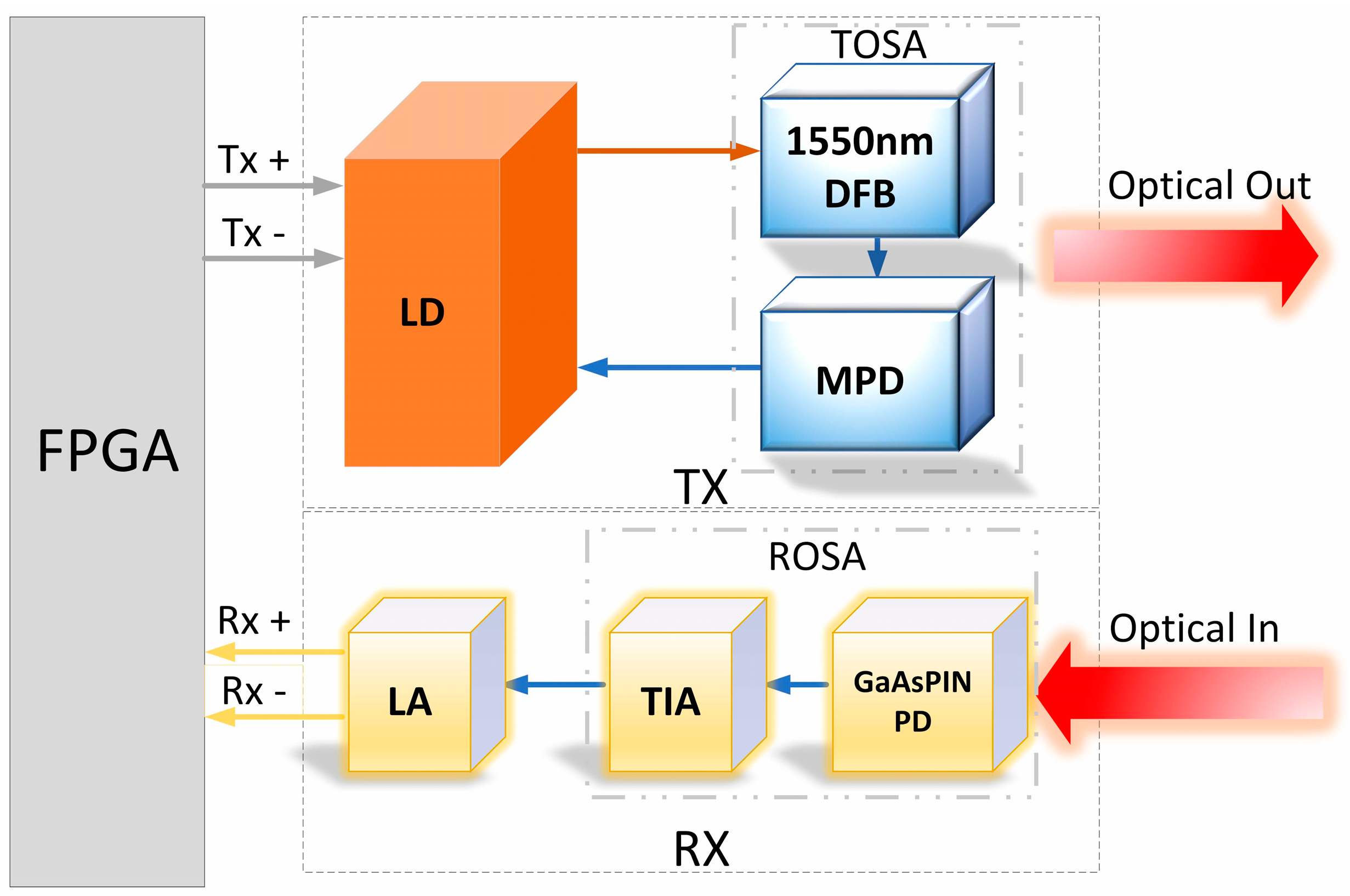
3.1. Optical Transceiver

As shown in Figure 4, the optical transceiver is divided into two parts, sending and receiving; the data rate is the same as that used in the traditional PTP protocol, which is 1.25 Gpbs. The sending part consists of the TOSA (Transmitter Optical Subassembly) and the laser driver, which realizes the electro-optical conversion of the signal. When working [26], the differential electrical signal sent from FPGA is input to the laser driver and is modulated into drive current and bias current. The DFB in the TOSA excites the 1550 nm optical signal under the action of the drive current, a part of which is sent out to the circulator to complete the data transmission, and the other part is sent to the MPD, which will collect the signal, perform the analog-to-digital conversion, and determine whether the power value of the signal is by the preset value. Real-time feedback regulation of the drive current of the LD output ensures the stability of the output optical power [27].
The receiving part consists of ROSA and a limiting amplifier to realize the photoelectric conversion of the signal [28]. When working, the PD receives the optical signal, which is converted into a current signal and sent to the TIA, and then converted into an attenuated differential electrical signal, which is then sent to the LA for amplification and shaping in order to ensure the accuracy of the signal recognition at the backstage, and finally sent to the FPGA for processing, and the data reception is completed [29].

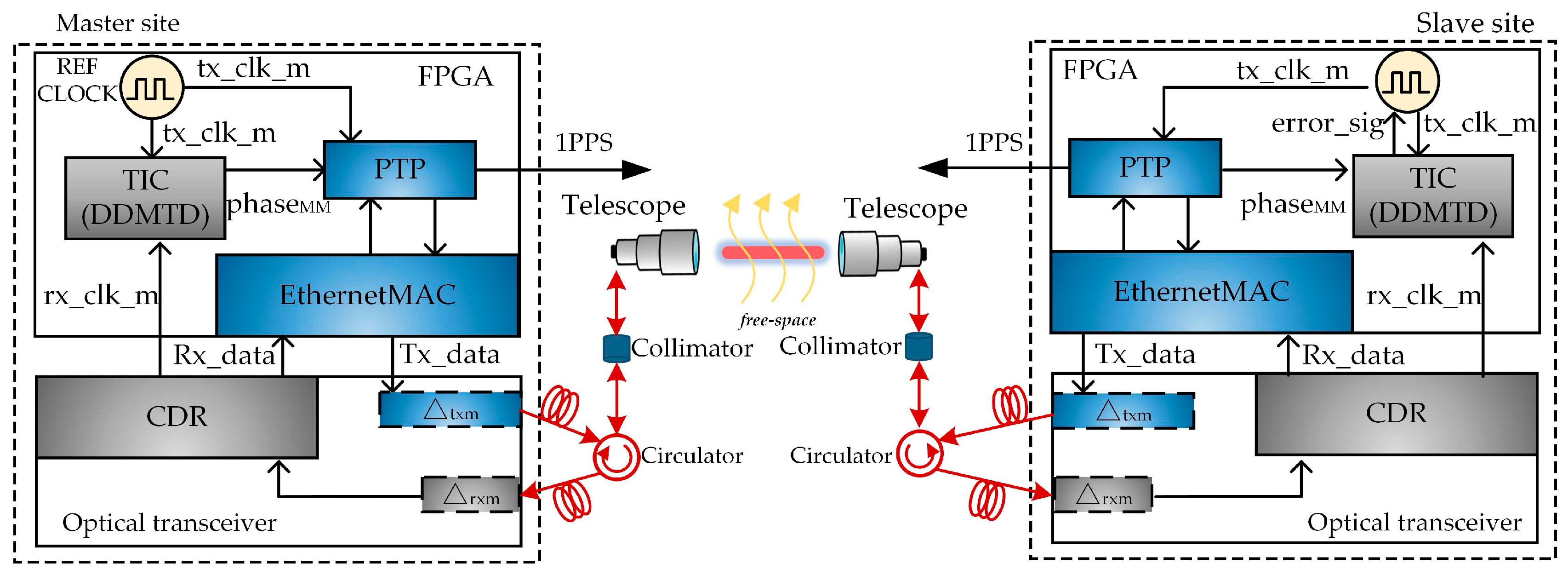
3.2. Schematic of WR Time Synchronization System

As shown in Figure 5, the system has two parts, master and slave sites, in which the master has a highly stable clock, and the synchronization is divided into the PTP protocol synchronization part and DDMTD part. In the beginning, the master sends PTP protocol data with time information, which are encapsulated at the MAC layer and then converted into optical signals via the Small Form Pluggable (SFP) transmitter at the physical layer. The signal is sent out through the circulator at the master end into a telescope, and in free space, this signal is transmitted into the telescope at the slave end, where it is received through the ringer at the slave end by the slave end’s SFP receiver port, converted into an electrical signal and recovered out of the master end’s transmit clock. The slave sends the clock into the TIC module of the slave, completes the DDMTD with the local clock of the slave, and obtains the phase difference value phaseMS transmitted from the master’s clock to the slave’s clock; the slave then sends the local time information to the master’s device, and similarly, the master recovers the slave’s clock and then performs a DDMTD of it, and obtains the phase difference value phaseMM transmitted from the slave’s clock to the master’s clock, and then sends this value back to the slave. The slave receives the two values, calculates the correct clock phase difference, and then changes the applied voltage value of the VCO of the PLL of the slave’s reference clock to complete the phase compensation.

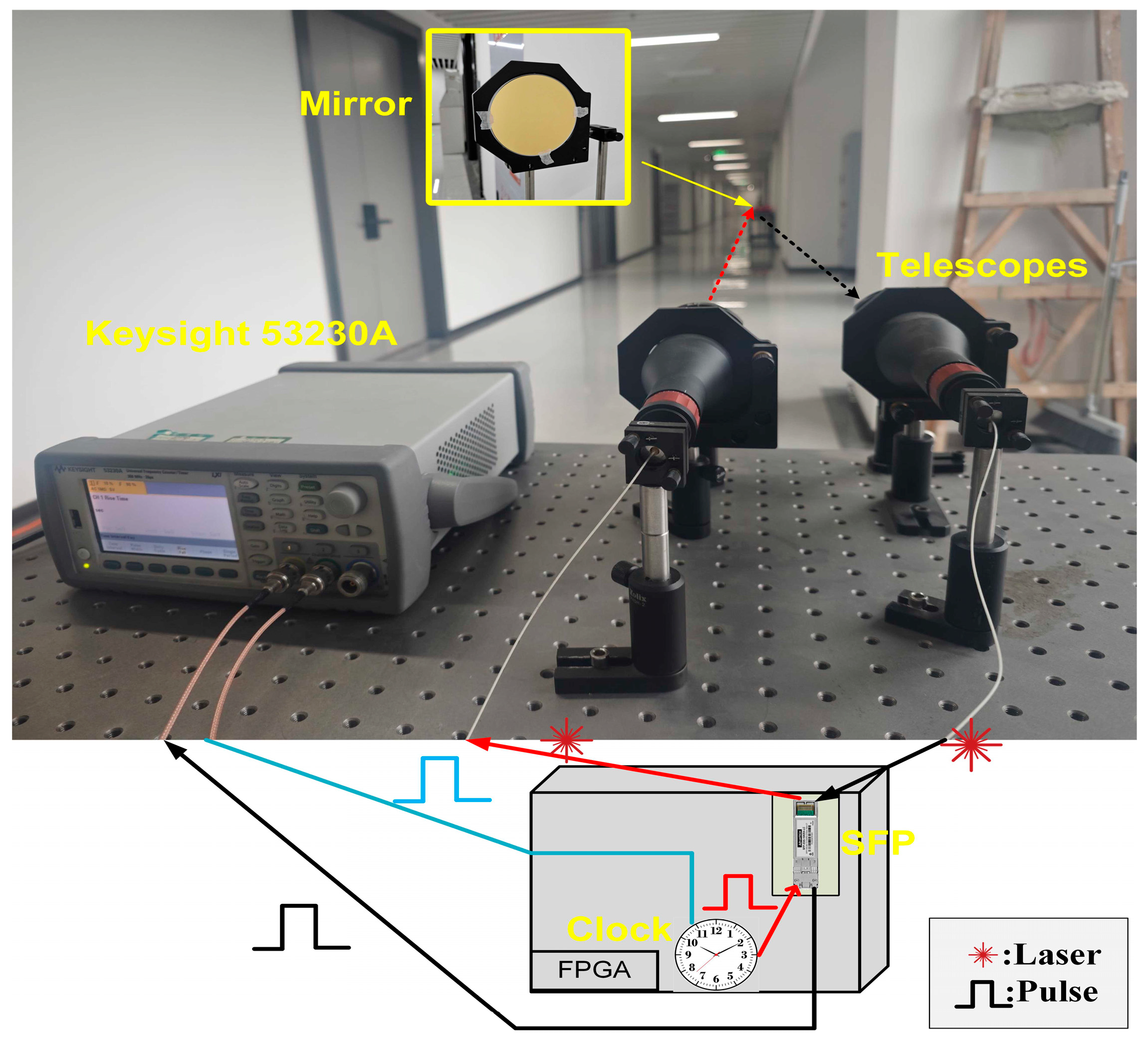
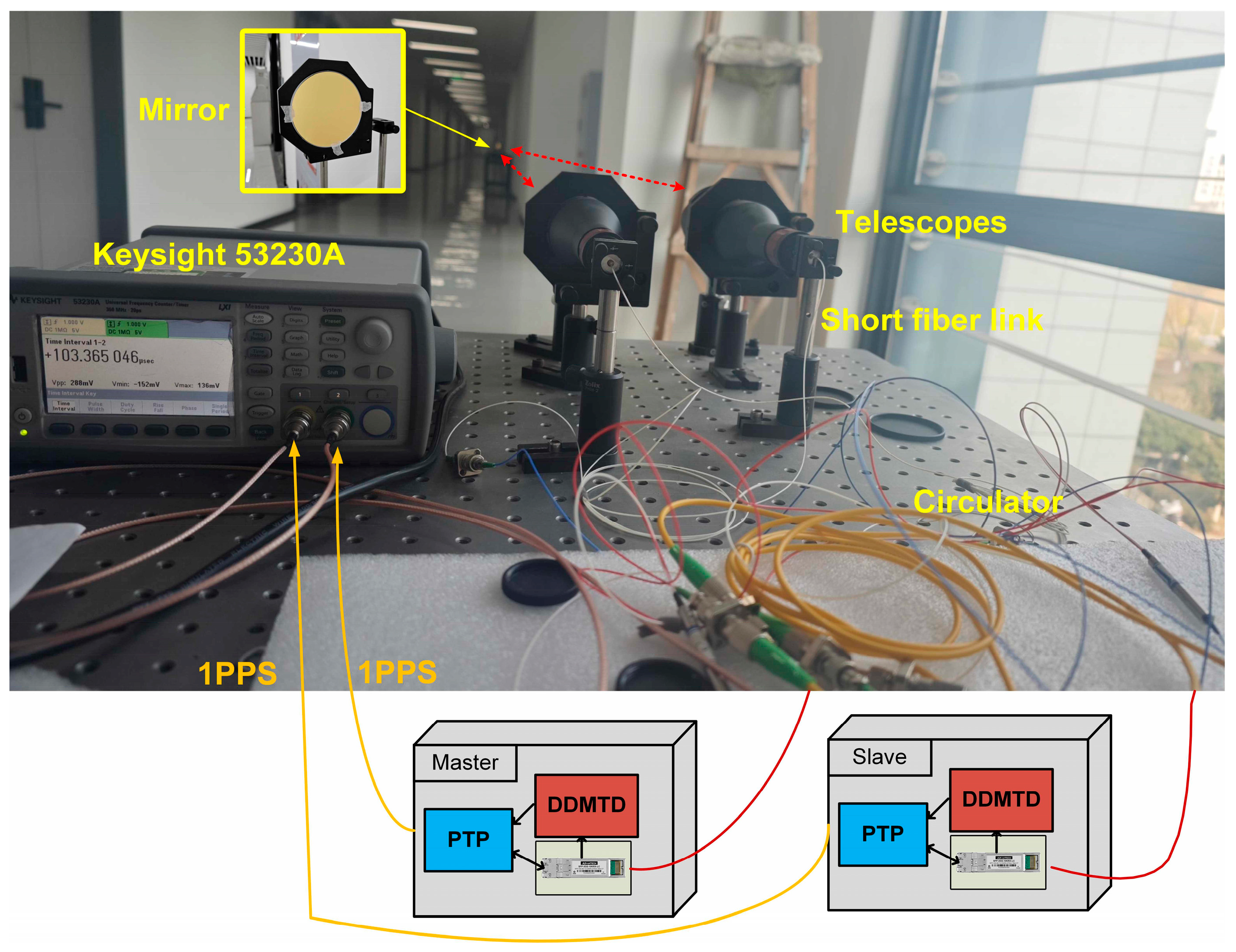
4. Experiment Setup and Result

We tested the time fluctuation of the optical link first, and the setup used for the test is shown in Figure 6. The setup is divided into local and remote ends, which are 25 m apart. A gold-coated reflector with diameter of 100 mm is placed at the remote end and a Time Frequency Counter, a transceiver, two collimators, and two telescopes with short fibers are placed at the local end. The telescope is the GBE20-C from THORLABS, Newton, USA; the collimator is the PHSH-2 from Zolix, Beijing, China; the reflector is a gold-plated copper reflector from PDV, Beijing, China; the Time Frequency Counter is the 53230A from Keysight, Santa Rosa, CA, USA; and the transceiver adopts the FPGA model of XC7A35T from Xilinx, Santa Clara, CA, USA, and uses their Vivado 2019.1 for development.
The clock in our device generates a pulse every second, and the pulse is sent in two ways. One to the laser module and the other is to the counter. The laser module converts the electronic 1 PPS signal into light pulses, and the pulse is sent to the reflector. The reflected light goes back to the same device, and is detected by the photodetector to output a 1 PPS signal. This 1 PPS signal is also fed into the counter, and the time interval between the two pulses is measured to obtain the time drift result of the optical link. The total length of this one-trip optical path is about 50 m.
The test results are shown in Figure 7. The vertical axis value in the figure has been subtracted by a fixed time delay of 50 m in length. It can be seen that without WR, there are short-term fluctuations of hundreds of picoseconds on the one-trip free space laser transfer link, and the RMS value of its long-term drift within 10 h is 92.9 ps.
Next, we conduct a time synchronization experiment, and the optical setup used for the experiment is shown in Figure 8. The experimental platform is based on the previous test with an additional set of transceivers and loopers, and a PTP module and a DDMTD module are added to the transceivers.
First, the optical path needs to be calibrated. After connecting the transceiver module, the facula of the light exiting the collimator is approximately 1 mm. Align the telescope so that the light exits from the center of the telescope, then adjust the focal length of the telescope to make the facula about 2 cm. Next, adjust the optical path to ensure that the light hits the reflector and is reflected to the center of the other telescope, and can be received by the collimator. Then, align the other one with the same operation.
Before synchronization begins, the two sets of transceivers are set up, with the one with the best clock stability set as the master and the other as the slave. Synchronization then begins, and the PTP module of the master sends the time signal out to the SFP module, where the time signal is converted from an electrical signal to an optical signal. The optical signal enters the circulator from the optical fiber, then enters the telescope, passes through the free space to the distal reflector, and is reflected to the telescope of the slave station. The total transmission distance between the master and the slave is about 50 m. The signal continues to pass through the circulator of the slave, is received by the SFP module, and is converted back to an electrical signal to be processed by the PTP module, completing the transmission of time information once. Every two information transmissions, the slave device can obtain a specific time interval measurement value, which is divided into the PTP value part and the DDMTD value part, in which the PTP part is directly compensated using the counter; the DDMTD part of the measured value is converted into an error signal, sent to the clock’s voltage-controlled oscillator, the frequency of the clock is adjusted, and the process is completed in the phase and the frequency of the double alignment until the phase error is less than the identifiable minimum, completing the synchronization. When synchronization is complete, the 125 MHz clock and 1 PPS of the slave device will be aligned with the master device. The 125 MHz clock is adjusted based on the alignment result of the 1 PPS, and the synchronization result of the 1 PPS has the same period as the WR synchronization, which better reflects the synchronization performance. Therefore, we chose to use 1 PPS as the measurement reference, while feeding 1 PPS from the master and slave into the 53230A, and then measuring and recording the time interval between the two 1 PPS.
We conducted a time synchronization experiment with a transmission distance of 50 m, and the duration is about 24 h. Figure 9 shows the experimental results of the free space WR-based synchronization.
Figure 9a shows that the short-term fluctuation of synchronization stabilizes at 100 ps with the use of WR, and the long-term drift is less than 50 ps with an RMS value of 20.5 ps for 24 h. Figure 9b shows that the TDEV of the time synchronization is 14.3 ps at 1 s and 3.9 ps at 20,000 s. The results show that the WR synchronization optical transmission channel in free space has a high degree of symmetry, effectively reducing the error in the two-way time comparison process.

5. Conclusions

We propose a free space synchronization scheme based on WR. This scheme improves the ubiquity of the WR technique so that the WR can also be used in wireless transmission to complete high-precision time synchronization. In this scheme, we abandon the typical WDM method and use only 1550 nm wavelength light combined with a circulator to complete the data transmission, which improves the symmetry of the link; at the same time, we design a >3 mW high-power SFP module to overcome the high loss of optical signals in free space links. The experimental results show that the RMS time drift of this free space synchronization system is 20.5 ps over 24 h. The TDEV of the time synchronization is 14.3 ps at 1 s and 3.9 ps at 20,000 s. The results also show that it is completely feasible to incorporate the WR technique in the free space, and it can perform time synchronization at the picosecond level.
The transmitter we designed has a maximum output power of 3 dBm, and the receiver’s recognition threshold is −31 dBm. The maximum attenuation is 34 dB. According to the general atmospheric attenuation model, the theoretical maximum transmission distance for light at a wavelength of 1550 nm is 100 m in an environment with visibility of no less than 10 km. However, optical devices also have certain attenuation, which means the transmission distance cannot be that far. Moreover, as the distance increases, the impact of environmental changes on the optical path becomes greater, making it difficult to maintain stable transmission for a long time. Therefore, we chose a distance of 50 m to complete the experiment. In future work, we will add anti-interference modules to deal with the impact of environmental changes, conduct more distance tests, and carry out outdoor testing.

Author Contributions

Conceptualization, P.Z. and D.H.; methodology, P.Z., D.H. and M.L.; software, P.Z. and W.Z.; investigation, K.L. and D.H.; data curation, P.Z.; validation, P.Z., D.H. and L.F.; writing—original draft preparation, P.Z.; writing—review and editing, D.H.; project administration, D.H. and K.L. funding acquisition, D.H. All authors have read and agreed to the published version of the manuscript.

Funding

This work was supported by the National Natural Science Foundation of China (62271109), and by the Natural Science Foundation of Sichuan Province of China (2023NSFSC0445).

Data Availability Statement

If you are interested in the software and platform produced in this paper, you can contact the authors at their email addresses.

Conflicts of Interest

The authors declare no conflicts of interest. The funders had no role in the study’s design, in the collection, analyses, or interpretation of the data, in the writing of the manuscript, nor in the decision to publish the results.

References

  1. IEEE Std 1588-2002; IEEE Standard for a Precision Clock Synchronization Protocol for Networked Measurement and Control Systems. IEEE: New York, NY, USA, 2002; pp. 1–154.
  2. IEEE Std 1588-2008 (Revision of IEEE Std 1588-2002); IEEE Standard for a Precision Clock Synchronization Protocol for Networked Measurement and Control Systems. IEEE: New York, NY, USA, 2008; pp. 1–269.
  3. Lipinski, M.; Wlostowski, T.; Serrano, J.; Alvarez, P.; Cobas, J.D.G.; Rubini, A. Performance results of the first White Rabbit installation for CNGS time transfer. In Proceedings of the 2012 IEEE International Symposium on Precision Clock Synchronization for Measurement, Control and Communication Proceedings, San Francisco, CA, USA, 24–28 September 2012. [Google Scholar]
  4. Dierikx, E.F.; Wallin, A.E.; Fordell, T.; Myyry, J.; Koponen, P.; Merimaa, M. White Rabbit Precision Time Protocol on Long-Distance Fiber Links. IEEE Trans. Ultrason. Ferroelectr. Freq. Control 2016, 63, 945–952. [Google Scholar] [CrossRef] [PubMed]
  5. Chang, K.; Sarihan, M.; Cheng, X.; Zhang, Z.; Wong, C. Large-alphabet time-bin quantum key distribution and Einstein–Podolsky–Rosen steering via dispersive optics. Quantum Sci. Technol. 2023, 9, 015018. [Google Scholar] [CrossRef]
  6. Gilligan, J.E.; Konitzer, E.M.; Siman-Tov, E.; Zobel, J.W.; Adles, E.J. White Rabbit Time and Frequency Transfer Over Wireless Millimeter-Wave Carriers. IEEE Trans. Ultrason. Ferroelectr. Freq. Control 2020, 67, 1946–1952. [Google Scholar] [CrossRef] [PubMed]
  7. IEEE Std 1588-2019 (Revision of IEEE Std 1588-2008); IEEE Standard for a Precision Clock Synchronization Protocol for Networked Measurement and Control Systems. IEEE: New York, NY, USA, 2019; pp. 1–499.
  8. Seijo, O.; Val, I.; Lopez-Fernandez, J.A.; Montalban, J.; Iradier, E. On the use of White Rabbit for Precise Time Transfer in 5G URLLC Networks for Factory Automation Applications. In Proceedings of the 2019 IEEE International Conference on Industrial Cyber Physical Systems (ICPS), Taipei, Taiwan, 6–9 May 2019; pp. 385–390. [Google Scholar]
  9. Lee, C.; Bunandar, D.; Zhang, Z.; Steinbrecher, G.R.; Dixon, P.B.; Wong, F.N.C.; Shapiro, J.H.; Hamilton, S.A.; Englund, D. Large-alphabet encoding for higher-rate quantum key distribution. Opt. Express 2019, 27, 17539–17549. [Google Scholar] [CrossRef] [PubMed]
  10. Kaur, N.; Frank, F.; Pottie, P.E.; Tuckey, P. Time and frequency transfer over a 500 km cascaded White Rabbit network. In Proceedings of the 2017 Joint Conference of the European Frequency and Time Forum and IEEE International Frequency Control Symposium (EFTF/IFCS), Besancon, France, 9–13 July 2017. [Google Scholar]
  11. Li, H.; Gong, G.; Pan, W.; Du, Q.; Li, J. Temperature Effect on White Rabbit Timing Link. IEEE Trans. Nucl. Sci. 2015, 62, 1021–1026. [Google Scholar] [CrossRef]
  12. Machnikowski, M.; Reddy, R.; Fodor, Z. Challenges with linuxptp on Telco RAN deployments. In Proceedings of the 2021 IEEE International Symposium on Precision Clock Synchronization for Measurement, Control, and Communication (ISPCS), NA, FL, USA, 27–28 October 2021. [Google Scholar]
  13. Lan, Y.; Chen, Y.; Hou, T.; Wu, B.; Chu, Y. Development Board Implementation and Chip Design of IEEE 1588 Clock Synchronization System Applied to Computer Networking. Electronics 2023, 12, 2166. [Google Scholar] [CrossRef]
  14. Correll, K.; Barendt, N. Design Considerations for Software Only Implementations of the IEEE 1588 Precision Time Protocol. In Proceedings of the Conference on IEEE 1588 Standard for a Precision Clock Synchronization Protocol for Networked Measurement and Control Systems, Winterhur, Switzerland, 10–12 October 2005. [Google Scholar]
  15. Khan, M.; Hayes, B. IEEE 1588 Time Synchronization in Power Distribution System Applications: Timestamping and Accuracy Requirements. IEEE Syst. J. 2023, 17, 2007–2017. [Google Scholar] [CrossRef]
  16. Rizzi, M.; Lipinski, M.; Ferrari, P.; Rinaldi, S.; Flammini, A. White Rabbit Clock Synchronization: Ultimate Limits on Close-In Phase Noise and Short-Term Stability Due to FPGA Implementation. IEEE Trans. Ultrason. Ferroelectr. Freq. Control 2018, 65, 1726–1737. [Google Scholar] [CrossRef] [PubMed]
  17. Park, K.; Park, I.-C. Fast frequency acquisition phase frequency detectors with prediction-based edge blocking. In Proceedings of the 2009 IEEE International Symposium on Circuits and Systems, Taipei, Taiwan, 24–27 May 2009. [Google Scholar]
  18. Guo, G.; Li, C.; Hou, D.; Liu, K.; Sun, F.; Zhang, S. Analysis and Implementation of a Frequency Synthesizer Based on Dual Phase-Locked Loops in Cesium Atomic Clock. Appl. Sci. 2013, 13, 9155. [Google Scholar] [CrossRef]
  19. David, W.A.; Herman, D. Picosecond Time Difference Measurement System. In Proceedings of the 29th Annual Symposium on Frequency Control, Atlantic City, NJ, USA, 28–30 May 1975. [Google Scholar]
  20. Bloom, B.J.; Nicholson, T.L.; Williams, J.R.; Campbell, S.L.; Bishof, M.; Zhang, X.; Zhang, W.; Bromley, S.L.; Ye, J. An optical lattice clock with accuracy and stability at the 10–18 level. Nature 2014, 506, 71–75. [Google Scholar] [CrossRef] [PubMed]
  21. Sprenger, B.; Zhang, J.; Lu, Z.; Wang, L. Atmospheric transfer of optical and radio frequency clock signals. Opt. Lett. 2009, 34, 965–967. [Google Scholar] [CrossRef] [PubMed]
  22. Sun, F.; Hou, D.; Zhang, D.; Tian, J.; Hu, J.; Huang, X.; Chen, S. Femtosecond-level timing fluctuation suppression in atmospheric frequency transfer with passive phase conjunction correction. Opt. Exp. 2017, 25, 21312–21320. [Google Scholar] [CrossRef] [PubMed]
  23. Wei, J.; Zhang, F.; Zhou, Y.; Ben, D.; Pan, S. Stable fiber delivery of radio-frequency signal based on passive phase correction. Opt. Lett. 2014, 39, 3360–3362. [Google Scholar] [CrossRef] [PubMed]
  24. Huang, W.; Chen, C.; Hou, D. Analysis of Underwater Optical Transfer of Radio-Frequency Signal in Turbulence Water Environment. In Proceedings of the 2023 IEEE 6th International Conference on Electronics and Communication Engineering (ICECE), Xi’an, China, 15–17 December 2023. [Google Scholar]
  25. Nie, J.; Yang, L.; Duan, L. Atmospheric transfer of a radio-frequency clock signal with a diode laser. Appl. Opt. 2012, 51, 8190–8194. [Google Scholar] [CrossRef] [PubMed]
  26. Ivanov, E.N.; Diddams, S.A.; Hollberg, L. Analysis of noise mechanisms limiting the frequency stability of microwave signals generated with a femtosecond laser. IEEE J. Sel. Top. Quantum Electron. 2003, 9, 1059–1065. [Google Scholar] [CrossRef]
  27. Soboń, G.; Martynkien, T.; Tomaszewska, D.; Tarnowski, K.; Mergo, P.; Sotor, J. All-in-fiber amplification and com pression of coherent frequency-shifted solitons tunable in the 1800–2000 nm range. Photon. Res. 2018, 6, 368–372. [Google Scholar] [CrossRef]
  28. Riehle, F. Optical clock networks. Nature Photon. 2017, 11, 25–31. [Google Scholar] [CrossRef]
  29. Chen, S.; Sun, F.; Bai, Q.; Chen, D.; Chen, Q.; Hou, D. Sub-picosecond timing fluctuation suppression in laser-based atmospheric transfer of microwave signal using electronic phase compensation. Opt. Commun. 2017, 401, 18–22. [Google Scholar] [CrossRef]
Figure 1. PTP message exchange.
Electronics 14 00970 g001
Figure 2. DDMTD circuit diagram.
Electronics 14 00970 g002
Figure 3. DDMTD measurement waveform schematic.
Electronics 14 00970 g003
Figure 4. Optical transceiver circuit diagram LD: laser driver; DFB: distributed feedback laser; MPD: monitor photodiode; LA: limiting amplifier; TIA: trans-impedance amplifier; PD: photodiode.
Electronics 14 00970 g004
Figure 5. Diagram of WR-based Time Synchronization System.
Electronics 14 00970 g005
Figure 6. Experimental setup for test of timing fluctuation for one-trip optical link.
Electronics 14 00970 g006
Figure 7. Results of time fluctuation on the one-trip optical link.
Electronics 14 00970 g007
Figure 8. Experimental setup of the WR time synchronization system.
Electronics 14 00970 g008
Figure 9. Results of the WR time synchronization experiment. (a) Time drift of WR synchronization. (b) Time drift of the WR synchronization.
Electronics 14 00970 g009
Table 1. Transmitter specifications.
ParameterValue
Optical Transmit Power3 dBm
Optical Center Wavelength1550 nm
Output Spectrum Width1 nm
Extinction Ratio12 dB
Table 2. Receiver specifications.
ParameterValue
Sensitivity−31 dBm
Wavelength of Operation1100~1610 nm
Signal Detect—Asserted−34 dBm
Signal Detect—De-asserted−45 dBm
Disclaimer/Publisher’s Note: The statements, opinions and data contained in all publications are solely those of the individual author(s) and contributor(s) and not of MDPI and/or the editor(s). MDPI and/or the editor(s) disclaim responsibility for any injury to people or property resulting from any ideas, methods, instructions or products referred to in the content.

