Abstract
A self-calibration method is proposed for determining the current ratio for DC current ratio devices. To demonstrate the feasibility of the proposal, an experimental test with nominal current ratios of 10:1 100:1 and 1000:1 is performed, and a three-step calibration procedure is used: Firstly, eleven magnetic modulator-based DC current transducers (DCCTs) with a nominal current ratio of 10:1 are used to realize the self-calibration of a 10:1 current ratio through the reference current method; secondly, the eleven DCCTs are series-parallel to achieve the current ratio build-up from 10:1 to 100:1; finally, another DCCT with a 100:1 auxiliary current ratio is used to realize the 1000:1 current ratio calibration, combining the two steps before. The merit of the proposed self-calibration method is that the measurement does not need a high-precision current source or ammeter. Current ratio calibration based on this technology offers a lower-cost, more robust alternative to those using other devices. The experimental results show that the uncertainty of the calibration, mainly dominated by the noise and the stability of the magnetic modulator used, is within a few parts in 10−7 or better in the 1000 A range.
1. Introduction
The heavy DC current measurement has a high demand in many fields, e.g., aluminum electrochemistry industry, HVDC power transmission, and strong magnetic field generation, etc. [1,2,3]. By far, the DC current transducers (DCCTs) based on the fluxgate or magnetic modulation principle are one of the most accurate solutions for converting heavy DC current into small signals that are suitable for high-precision electrical measurements. In the past decade, DCCTs have been widely used in measurements such as power system, particle accelerator power supply, NUCLEAR magnetic resonance gradient amplifier, power battery testing, high-end electrical instrumentation, electric vehicle charging pile, and so on. Differs from other alternatives, e.g., shunt [4], the DCCT can yield much higher accuracy, as the measurement result is related to almost only the primary-secondary ratio of winding turns, which is less sensitive to environmental factors, e.g., the thermal effect. The measurement range of a DCCT can be up to tens of thousands of amperes, whose accuracy is typically as high as 10−5 with a nonlinearity lower than 10−6 [5,6].
For calibrating high-precision DC current ratio devices, a complex calibration device is usually required to achieve small uncertainties [7,8]. At present, some national metrology institutes (NMIs) have developed several methods for calibrating the current ratio of DCCT devices [6,9]. In general, these calibration methods are in two categories: one is using a high-accuracy DC current comparator (DCC), large current range extender, and low-value standard resistors [10,11], while the other is the traditional ratio build-up method [12]. As mentioned, the drawback is that both methods require a complicated hardware system, especially for high current ratio calibrations. The solution based on high-accuracy current comparators, range expanders, and low-resistance shunt resistors typically enables current ratio calibration and measurement with a range of 10−7. However, the equipment required for this solution is usually only available in national metrology institutes and similar organizations. Moreover, the entire system is large and costly, making it impractical for convenient calibration of the current ratio of the tested instruments. In contrast, the traditional calibration solution, while simple and low-cost, is limited to a calibration range of up to 50 A and has an uncertainty specification of only 10 ppm, which no longer meets the calibration requirements for high-precision current ratio devices [13].
These methods enable NMIs equipped with DCCs to calibrate commercial DCCTs; however, DCCs themselves also require calibrations. Ratio is a dimensionless quantity, and their calibrations should not have to rely on the highest national metrology institutions [14]. Therefore, some simple methods should be put forward to extend the operability and simplification of the system usability.
In this paper, a simple self-calibration method is proposed for determining the DC current ratio devices. The traditional reference potential method used for calibrating the induced voltage divider is here transformed into a reference current method for calibrating current ratios through the reciprocity principle. Compared to other DC current ratio calibration methods, the proposal can easily calibrate the current ratio of high-precision DCCT and other current ratio devices (like DCCs) only depending on several modified DCCTs. Then the paper is organized as follows: In the next section, the homemade DC current ratio device, which is applied to the self-calibration method, will be introduced, and in Section 3, the calibration principle, including the method of how to calibrate the 10:1, 100:1, and 1000:1 current ratios, will be elaborated, respectively. The results of the current ratios of the self-calibration method and the device fabricated in the laboratory will be presented in Section 4, respectively.
2. DC Current Ratio Device
As one kind of DC current ratio device, a DC current transducer (DCCT) is an ampere-turns device used in this self-calibration method. The DCCT is composed of three parts: the primary winding NP, the secondary winding NS and the magnetic modulator, while the basic principle of DCCT is shown in Figure 1a. Typically, a DC signal does not generate an induced magnetic flux like an AC signal, making it unsuitable for direct detection. Therefore, for a DCCT, a design method capable of modulating and demodulating the DC signal is required. The method widely used at present is the magnetic modulator, which then converts the input DC current signal into a DC voltage signal for feedback through a peak detector. The sensitivity Z is the ratio of the detected DC voltage signal to the input DC signal. The higher the sensitivity, the stronger the sensor’s ability to detect weak current signals, and the lower the noise level of the DCCT. When the primary current IP has access to the primary winding NP, the unbalanced magnetic flux can be detected by the magnetic modulator, and the unbalanced magnetic flux would be turned into the induced voltage VD, as a consequence, the secondary winding NS receives a compensating current aimed to balance the ampere-turns of the DCCT. Taking the errors (introduced by the magnetic leakage and the feedback system of the DCCT) into account, the primary current IP and the secondary current IS satisfy the following relationship below, which keeps the primary magnetic potential and the secondary magnetic potential balanced. The DCCT is a dimensionless current scaling device, meaning that the primary current IP to be measured is converted into a smaller secondary current IS through a strict turns ratio, facilitating the detection of the measured current. Note that the sensitivity Z of DCCT can be shown to be, , where is the overall magnetic potential [15,16]. And current IS is produced by the feedback loop, similar to direct-current current comparators (DCCs) [17,18,19].
where IP and IS are the primary and secondary current, respectively, while NP and NS are represented as the turns of the primary and secondary winding, respectively. And denotes the magnetic potential error. A simplified schematic diagram of DCCT based on the magnetic modulator is illustrated in Figure 1b. The asterisk indicates the positive direction of DCCT.
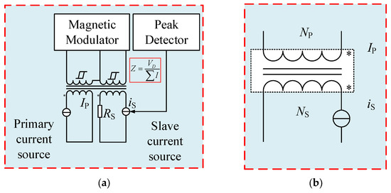
Figure 1.
(a) Schematic of DCCT. (b) Simplified equivalent circuit of DCCT.
From Equation (1):
where ,, and is the error of the current ratio.
It can be seen from Equation (2) that the self-calibration of the current ratio is essential to obtain the error for determining the real current ratio between the primary and secondary current within a certain range of uncertainty.
Figure 2a is the physical picture of DCCT based on the magnetic modulator, which is applied to this paper. The secondary winding of each DCCT is 1000 turns, while the current ratio of 10:1 and 100:1 is formed by adding auxiliary primary windings (100 turns and 10 turns), respectively. Subsequently, the simplified equivalent circuit of the DCCT with auxiliary windings is shown in Figure 2b, for the sake of the description of the self-calibration method. Moreover, the current characteristic from the output offset of one DCCT is illustrated in Figure 3, which shows the overall noise level of the DCCT. In the self-calibration method described in this paper, the DCCTs are such critical components that optimized homemade DCCTs should be selected. The output offset of the optimized DCCT has been tested for 15 min; 0 mA × turns and 1 mA × turns of the input current are shown in Figure 3. Note that the stability of the homemade DCCT shown in Figure 3 is better than a few parts in 10−8, so as to the performance of the other DCCTs, which is not specified in this paper. The DCCT is a dimensionless current scaling device. When there is no primary current IP, the secondary current IS outputs a non-zero bias (on the order of uA). Due to the high signal-to-noise ratio of the DCCT used in this article, when an input current of 100 uA is applied, the secondary output current of the DCCT still functions normally, meeting the design requirements for the subsequent stages of this research. The Y-axis of the graph represents the secondary current output of the DCCT, measured in milliamperes multiplied by the number of turns, which corresponds to the dimension of magnetomotive force. Figure 3 demonstrates the high signal-to-noise ratio of the self-developed DCCT used in this paper.
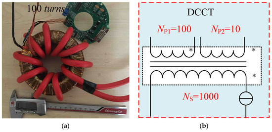
Figure 2.
(a) Image of DCCT after auxiliary windings are added. (b) Simplified equivalent circuit of DCCT after auxiliary windings are added.
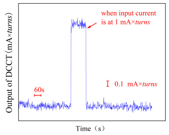
Figure 3.
Current characteristic from the offset of DCCT.
3. Calibration Principle
3.1. Calibration of 10:1 (10 A:1 A) Current Ratio
Step 1: One of the 11 DCCTs with a nominal current ratio of 10:1 is named Tr. As a reference DCCT, it is compared with the other 10 DCCTs named Ti (from T1 to T10) with the same 10:1 current ratio (Figure 4). To facilitate the calculation, K0.1–i is defined as the 10:1 current ratio of the ith DCCT.
where IP, K0.1−i, and K0.1−r are expressed as the primary current, current ratio of ith DCCT, and reference DCCT, respectively. and refer to the output and ratio differences of the secondary current between the ith DCCT and reference DCCT, respectively.
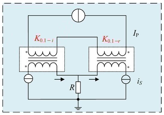
Figure 4.
Permutation setup for step 1 of the 10:1 current ratio of 11 DCCTs.
Step 2: After the ten 10:1 current ratio DCCTs are compared with the reference DCCT in turn, the ten DCCTs are connected according to the way shown in Figure 5, so that the primary windings of the ten DCCTs are in series while the secondary windings are in parallel. It can be formulized in Equations (5) and (6):
where refers to the difference between the primary current IP and the secondary currents in parallel, refers to the ratio between and the primary current IP, respectively.
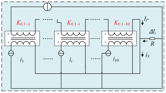
Figure 5.
Permutation setup for step 2 of the 10:1 current ratio of 11 DCCTs.
According to Equations (4) and (6), the 10:1 current ratio of each DCCT can be calculated.
where denotes the 10:1 current ratio error of the ith DCCT. Note that a high-precision amperemeter is not essential in the calibration of a 10:1 (10 A:1 A) current ratio, and only the difference in current is tested and recorded. Moreover, actions should be taken to eliminate the influence of the output offset of each DCCT by reversing the primary current in each operation.
3.2. Calibration of 100:1 (100 A:1 A) Current Ratio
After the self-calibration of the 10:1 current ratio is completed, the calibration of the 100:1 and 1000:1 current ratios can be realized conveniently. The following is a brief introduction to the build-up calibration method of the current ratio from 10:1 to 100:1.
Eleven DCCTs with a 10:1 current ratio are used to form a two-stage composite DCCT with a nominal current ratio of 100:1, as shown in Figure 6, stage 1 and stage 2. The stage 1 construction is composed of ten DCCTs with 10:1 current ratio calibrated. When all of the ten primary windings stay in parallel, a current ratio of 10:1 (100 A:10 A) can be achieved if all of the ten secondary windings stay in parallel too. Then a cascaded current ratio of the composite DCCTs is 100:1 when the stage 2 construction is composed of a calibrated 10:1 current ratio (10 A:1 A) DCCT. The current ratio of the two-stage composite DCCT is defined as K0.01.
where is the average value of the 10:1 current ratio error of 10 DCCTs at stage 1, and is the 10:1 (10 A:1 A) current ratio error of the 11th DCCTs at stage 2.
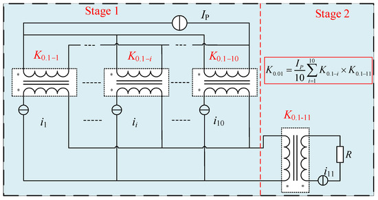
Figure 6.
Permutation setup for the self-calibration of 100:1 current ratio.
3.3. Calibration of 1000:1 (1000 A:1 A) Current Ratio
In order to facilitate the calculation, K0.01-i is defined as the 100:1 current ratio of the ith DCCT, and several steps are involved to complete the calibration of the 1000:1 (1000 A:1 A) current ratio. The first step is to use the two-stage composite DCCT with a 100:1 current ratio to calibrate the 12th DCCT with an auxiliary 100:1 (100 A:1 A) current ratio K0.01–12, shown in Figure 7.
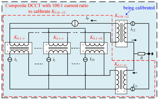
Figure 7.
Calibration of the 100:1 current ratio of the 12th DCCT.
The second step is to switch each of the 10 DCCTs primary windings into 10 turns. Subsequently, a new 100:1 (100 A:1 A) composite DCCT with primary windings in series and secondary windings in parallel is formed (Figure 8). Because the 100:1 current ratio of the 12th DCCT has been calibrated in the previous step, the 100:1 current ratio of the new composite DCCT can be calibrated easily. From Figure 7 and Figure 8, the 12th DCCT, which has an auxiliary 100:1 (100 A:1 A) current ratio K0.01−12, is used just as a reference to calibrate the new composite DCCT with the 100:1 current ratio.
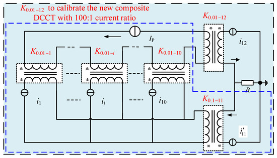
Figure 8.
Calibration of the new composite DCCT with 100:1 current ratio.
In the third step, the primary windings of the ten DCCTs are switched from series mode to parallel mode while the secondary windings remain in the parallel mode unchanged, so the 100:1 (1000 A:100 A) current ratio can be obtained. Then the composite DCCT with calibrated 100:1 (1000 A:100 A) current ratio and one DCCT with calibrated 10:1 current ratio (K0.1–11) are combined to form a new two-stage composite 1000:1 (1000 A:1 A) DCCT shown in Figure 9, where the self-calibration of the DC current ratio is finally realized. The current ratio of the new two-stage composite 1000:1 DCCT is K0.001.
where denotes the current ratio error of the 100:1 (1000 A:10 A) DCCT of the new stage 1, and γ represents the current ratio error of 1000:1 (1000 A:1 A).
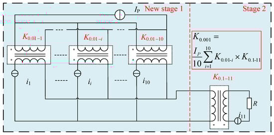
Figure 9.
Permutation setup for the self-calibration of 1000:1 current ratio.
The self-calibration method for accurate direct-current current ratio calibration contains three steps: the calibration of 10:1 (10 A:1 A) current ratio, the calibration of 100:1 (100 A:1 A) current ratio, and the calibration of 1000:1 (1000 A:1 A) current ratio. It is fairly easy to calibrate the current ratios of 100:1 and 1000:1, followed by the self-calibration of 10:1 current ratio of each DCCT. Moreover, in the case of DC measurements, a great deal of attention must be given to eliminate the DC output offset, and the usual way to solve this problem is to derive the value of the result from two measurements carried out with currents of opposite signs.
4. Calibration Device and Results
4.1. Self-Calibration Device
A self-calibration device has been built for the sake of realizing the calibration of the 1000:1 current ratio. The 12 homemade DCCTs with 10 turns and 100 turns auxiliary windings just described in Section 2 were fabricated and assembled in a standard 5U 19-inch chassis, while the 10:1 current ratio inport is designed at the front panel and the inports of 10:1 and 100:1 current ratios are designed at the back panel of the standard 5U 19 inch chassis, respectively. Moreover, all of the input/output terminals of each DCCT are connected to the chassis panel through some banana sockets and connectors, which can realize series and parallel functions, while the output terminals of all DCCTs are shorted or connected in parallel through the single-pole double-throw (SPDT) switches on the panel. Figure 10 shows the 5U chassis and connectors with 12 DCCTs, while an amperemeter and a current source with a full-scale range of 800 A are needed in the process of the self-calibration.
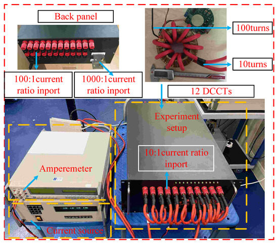
Figure 10.
Experimental setup.
4.2. Calibration Result
Figure 11 and Figure 12 show the self-calibration data of the 10:1, 100:1, and 1000:1 current ratios. Table 1, Table 2 and Table 3 show the measurement uncertainty evaluation when the input magnetic potential is 200 A × turns of the 10:1, 100:1, and 1000:1 current ratios. Type A uncertainty mainly comes from measurement repeatability, whereas type B uncertainty mainly comes from the accuracy and stability of DCCTs and the current source, notwithstanding differences in the winding resistance and contact resistance caused by parallel current shunt inhomogeneity and other factors. However, in the experimental process, the contribution of the above factors to the uncertainty of measurement is relatively small. It has little influence on the evaluation of actual measurement uncertainty. Table 1, Table 2 and Table 3 list some factors that affect the evaluation of the measurement uncertainty of type B and analyze the contribution to the uncertainty of the measurement of type B. The error bars of the 1000:1 current ratio error under different input currents are shown in Figure 13.
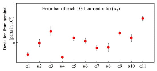
Figure 11.
Error bar of each 10:1 current ratio.
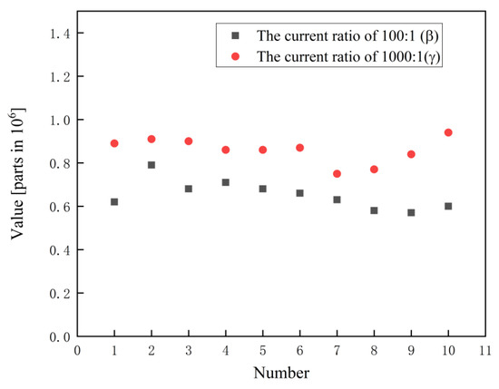
Figure 12.
Self-calibration data at the ratios of 100:1 and 1000:1 (input current is 200 A × turns).

Table 1.
Uncertainty budget for the 10:1 current ratio of the 11th DCCT at 200 A × turns.
Table 2.
Uncertainty budget for the 100:1 ratio of the standard DCCT at 200 A × turns.
Table 3.
Uncertainty budget for the 1000:1 ratio of the standard DCCT at 200 A × turns.
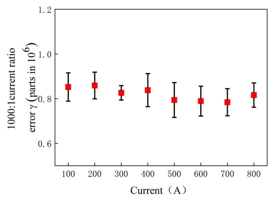
Figure 13.
Self-calibration result of the 1000:1 ratio when applying different current.
In Table 1 and Table 2, U(α)A and U(α)B represent the standard uncertainties of Class A and Class B, respectively. The current source used has an amplitude of 2.445 A, with a standard uncertainty of 6 mA, and the standard uncertainty of the ammeter is 10 nA. Based on and , the expanded uncertainty can be obtained in Table 1 and Table 2, respectively.
Where and .
In Table 3, the contributions from both class A and class B uncertainties are calculated step by step. The current source used has an amplitude of 24.95 A, with a standard uncertainty of 7 mA. By applying the formulas mentioned above, the expanded uncertainty for each level of current ratio self-calibration can be determined. These calculations provide a comprehensive understanding of the uncertainty associated with the calibration process, ensuring that each step is accounted for in the final measurement results.
5. Conclusions
In this paper, a lower-cost, more robust self-calibration method of DC current ratio calibration is proposed, which can conveniently calibrate the required DC current ratio without a high-precision current source or ammeter. Aiming at calibrating DC current ratios of 10:1, 100:1, and 1000:1, a DC current ratio self-calibration device is built in this paper. Within the input current range of 1000 A, the uncertainty of the 1000:1 current ratio self-calibration is better than a few parts in 10−7. Although the device has performed well by using the several steps described above, still some rooms are left with the uncertainty field for the further investigations and development. The calibration uncertainty is mainly limited by the noise and short-term stability of DCCTs. Following this initial development version and by reducing the noise and improving the short-term stability of DCCTs, the uncertainty of the measurement results can be further improved. Since the most commonly used current ratio calibration devices are typically 10n:1, the design in this paper is based on this common requirement. Of course, other ratios, such as 5:1, 20:1, and 2000:1, can also be calibrated by adjusting the number of DCCTs and the turns ratio of each DCCT’s primary and secondary windings. However, since modifying the turns ratio of each DCCT is involved, for existing equipment with fixed turns ratios, additional work is required to complete the modification.
Author Contributions
The study presented here was conducted in collaboration between all authors. C.Z. and J.Z. wrote the paper and designed the idea; Y.L., K.Z. and P.H. improved the idea and experiment; J.Z. drew the main conclusions and critically reviewed the paper. All authors have read and agreed to the published version of the manuscript.
Funding
This work was supported in part by the National Key R&D Program of China (2023YFF0612502) and in part by the Basic Science Research Funding in the National Institute of Metrology (AKYZD2106).
Data Availability Statement
The experimental data presented in this study are available upon reasonable request from the corresponding authors.
Conflicts of Interest
The authors declare no conflicts of interest.
References
- Rudervall, R.; Charpentier, J.P.; Sharma, R. High voltage direct current (HVDC) transmission systems technology review paper. In Proceedings of the Energy Week 2000, Washington, DC, USA, 7–8 March 2000; pp. 1–19. [Google Scholar]
- Bastos, M.C.; Fernqvist, G.; Hudson, G.; Pett, J.; Cantone, A.; Power, F.; Saab, A.; Halvarsson, B.; Pickering, J. High accuracy current measurement in the main power converters of the large hadron collider: Tutorial 53. IEEE Instrum. Meas. Mag. 2014, 17, 66–73. [Google Scholar] [CrossRef]
- Hudson, G.; Bouwknegt, K. 4–13 kA DC current transducers enabling accurate in-situ calibration for a new particle accelerator project, LHC. In Proceedings of the 2005 European Conference on Power Electronics and Applications, Dresden, Germany, 11–14 September 2005; pp. 1–8, 4–13. [Google Scholar]
- Rubioa, E. High-stability current in the 10 A range. IEEE Trans. Instrum. Meas. 1996, 45, 865–871. [Google Scholar] [CrossRef]
- Ripka, P. Electric current sensors: A review. Meas. Sci. Technol. 2010, 21, 112001. [Google Scholar] [CrossRef]
- Filanovsky, I.M.; Piskarev, V.A. Sensing; Measurement of dc current using a trans-former and RL-multivibrator. IEEE Trans. Circuits Syst. 1991, 38, 1366–1370. [Google Scholar]
- Zhao, J.; Lu, Y.; Zhai, C.; He, Q.; Huang, X.; Wang, Y. Method for the absolute calibration of direct-current current transducers. IEEE Trans. Instrum. Meas. 2019, 68, 1961–1966. [Google Scholar] [CrossRef]
- Unser, K. Beam current transformer with DC to 200 MHz range. IEEE Trans. Nucl. Sci. 1969, 16, 934–938. [Google Scholar] [CrossRef]
- Unser, K. A toroidal DC beam current transformer with high resolution. IEEE Trans. Nucl. Sci. 1981, 28, 2344–2346. [Google Scholar] [CrossRef]
- Callegaro, L.; Cassiago, C.; Gasparotto, E. On the calibration of direct-current cur-rent transformers (DCCT). IEEE Trans. Instrum. Meas. 2015, 64, 723–727. [Google Scholar] [CrossRef]
- Rietveld, G.; van der Beek, J.H.N.; Houtzager, E. Accurate high-current DC current ratio measurements. IEEE Trans. Instrum. Meas. 2015, 64, 3055–3061. [Google Scholar] [CrossRef]
- Shao, H.; Lin, F.; Liang, B.; Hua, X.; Lu, Y.; Qu, K.; Pan, Y.; Zhang, Z.; Chen, W.; Su, H. DC 5 kA current ratio standards based on series–parallel self-calibration DCCs. IEEE Trans. Instrum. Meas. 2013, 62, 3093–3100. [Google Scholar] [CrossRef]
- Zhao, H.; Zhang, X.; Liu, Y.; Zheng, L.; Zou, B. Calibration of DC current up to 600 A. In Proceedings of the CPEM 2010, Daejeon, Republic of Korea, 13–18 June 2010; pp. 603–604. [Google Scholar]
- Zhao, J.; Lu, Y.; He, Q.; Wang, Y. Method for the Absolute Calibration of Direct-Current Current Transducers. In Proceedings of the 2018 Conference on Precision Electromagnetic Measurements (CPEM 2018), Paris, France, 8–13 July 2018; pp. 1–2. [Google Scholar]
- Miljanic, P.N.; Kusters, N.L.; Moore, W.J.M. The development of the current comparator, a high-accuracy A-C ratio measuring device. Trans. Am. Inst. Electr. Eng. Part I Commun. Electron. 1962, 81, 359–368. [Google Scholar] [CrossRef]
- Satrapinski, A.; Götz, M.; Pesel, E.; Fletcher, N.; Gournay, P.; Rolland, B. New Generation of Low-Frequency Current Comparators Operated at Room Temperature. IEEE Trans. Instrum. Meas. 2017, 66, 1417–1424. [Google Scholar] [CrossRef]
- Brown, D.; Wachowicz, A.; Huang, S. AccuBridge™ towards the development of a DC Current Comparator resistance ratio standard. In Proceedings of the CPEM 2010, Daejeon, Republic of Korea; 2010; pp. 639–640. [Google Scholar]
- Brown, D.; Wachowicz, A.; Huang, S. The enhanced performance of the DCC current comparator using AccuBridge® technology. In Proceedings of the 2016 Conference on Precision Electromagnetic Measurements (CPEM 2016), Ottawa, ON, Canada, 10–15 July 2016; pp. 1–2. [Google Scholar]
- Pollarolo, A.; Brown, D.; Huang, S.; Wachowicz, A.; Brown, R. Quantum Hall Resistance Verification Based on a Direct Current Comparator Bridge. In Proceedings of the 2018 Conference on Precision Electromagnetic Measurements (CPEM 2018), Paris, France, 8–13 July 2018; pp. 1–2. [Google Scholar]
Disclaimer/Publisher’s Note: The statements, opinions and data contained in all publications are solely those of the individual author(s) and contributor(s) and not of MDPI and/or the editor(s). MDPI and/or the editor(s) disclaim responsibility for any injury to people or property resulting from any ideas, methods, instructions or products referred to in the content. |
© 2025 by the authors. Licensee MDPI, Basel, Switzerland. This article is an open access article distributed under the terms and conditions of the Creative Commons Attribution (CC BY) license (https://creativecommons.org/licenses/by/4.0/).