Abstract
This paper conducts an in-depth study on the application of inductor-capacitor-inductor (LCL) filters in grid-connected photovoltaic (PV) inverters. First, the resonance issues associated with LCL filters are analyzed, and solutions are discussed, with a focus on the implementation of passive damping strategies. Various passive damping schemes, based on the placement of resistors (R), are compared and analyzed, ultimately selecting the capacitor branch series resistor as the optimal solution. During the design process, multiple parameters, such as total inductance, inverter-side inductance, grid-side inductance, capacitance, and damping resistors, are considered in light of their mutual constraints. Detailed analysis and optimization of these parameters are performed based on steady-state operation, current ripple, and power loss limitations. Finally, it is concluded that the passive damping solution using a series resistor in the capacitor branch meets the requirements for stable operation and efficient filtering. The optimal solutions are identified as R1 = 0, R2 = ∞, R3 ≠ 0, and R4 = ∞, providing a reliable and effective filtering solution for grid-connected PV inverter systems.
1. Introduction
As the global energy landscape shifts towards renewable sources, grid-connected photovoltaic-storage systems have emerged as a critical technological solution for enhancing energy efficiency, reducing carbon emissions, and improving grid stability. By integrating photovoltaic (PV) power generation with energy storage technology, these systems not only increase the penetration of renewable energy but also optimize power supply through flexible energy management. However, one of the key challenges affecting their operational performance is the issue of power quality on the inverter side [1,2].
In PV-storage systems, LCL (inductor–capacitor–inductor) filters are widely utilized in grid-connected inverters to suppress high-frequency harmonics, enhance power quality, and minimize grid interference [3,4,5]. Their ability to provide superior harmonic attenuation compared to conventional LC filters makes them particularly suitable for mitigating switching noise in power electronics-based renewable energy systems [6,7]. However, the multi-order structure of LCL filters introduces inherent resonance issues. At specific frequency points, these filters can exhibit pronounced resonance peaks, leading to current distortion, system instability, and potential amplification of resonant effects on the grid side. Furthermore, the phase response characteristics of LCL filters may introduce a 180° phase shift, further complicating the stability of the inverter control loop and increasing the complexity of system regulation [8,9].
Addressing the resonance issue in LCL filters has become a central research focus in PV grid integration. Various damping strategies have been proposed to mitigate resonance effects, including passive damping, active damping, and hybrid damping techniques [10,11,12]. However, existing solutions still face several unresolved challenges: Firstly, while numerous studies have examined the resonance behavior of LCL filters, a comprehensive and in-depth investigation into resonance point identification and its impact on system stability—especially in the presence of a 180° phase shift—remains insufficient [13,14]. The dynamic response of LCL filters under real-world operating conditions, such as varying grid strengths and inverter control strategies, requires further exploration [15]. Secondly, while passive damping methods, such as series and parallel resistors, have been proposed, a rigorous comparison of their effectiveness under different operating conditions is lacking [16]. The trade-offs between resonance suppression, system efficiency, and power losses remain an open research question that requires both experimental validation and theoretical analysis [17]. Additionally, the effectiveness of LCL filters is influenced by external factors such as climate conditions, solar irradiance, grid loads, and state-of-charge variations in storage systems [18,19]. However, the existing research has not sufficiently addressed how these factors impact filter performance and resonance characteristics, particularly in weak-grid environments [20]. Lastly, despite the theoretical advancements in LCL filter design, there remains a gap in real-world implementation studies that evaluate their long-term stability, operational feasibility, and cost-effectiveness under diverse grid conditions [15,21]. A comprehensive assessment integrating real-world data, simulation studies, and practical case analyses is needed to validate the applicability of the proposed damping techniques [22].
Given the existing research gaps, advancing the application of LCL filters in PV-storage systems necessitates a comprehensive and systematic approach to resonance suppression, passive damping optimization, and system stability enhancement. This study proposes an innovative passive damping strategy specifically tailored for grid-connected PV-storage systems. Unlike conventional methods, which often focus on either series or parallel resistors, this study introduces an optimized capacitor-branch series resistor damping scheme that effectively balances resonance attenuation, power loss minimization, and system efficiency. The key contributions of this research are: Firstly, the proposed capacitor-branch series resistor scheme is systematically designed and optimized to provide superior resonance suppression while minimizing its impact on system efficiency, a challenge not fully addressed in prior works. Secondly, unlike previous studies that rely on empirical or approximate methods, this research employs a rigorous theoretical framework to derive optimal damping parameters, ensuring both robust system stability and minimal power dissipation. Thirdly, while many studies focus on theoretical simulations, this research validates the proposed damping strategy through experimental analysis, demonstrating its effectiveness in real-world grid-connected PV-storage scenarios.
The application of LCL filters in PV-storage systems remains a rapidly evolving research domain with substantial potential for improving power quality, mitigating harmonic distortions, and stabilizing grid interactions. While recent advancements have demonstrated their benefits, most existing solutions lack a structured optimization framework that balances stability, efficiency, and real-world applicability. This research bridges that gap by introducing a performance-optimized passive damping strategy, incorporating both theoretical rigor and experimental verification to ensure practical feasibility. By addressing the key challenges in LCL filter damping, this study contributes to the development of high-performance, cost-effective, and scalable solutions for integrating renewable energy into modern power grids.
2. Filter Design for Photovoltaic-Storage Integrated Systems
Grid-connected photovoltaic-storage inverters typically operate at high frequencies in the kHz range, which generates a significant amount of high-frequency switching harmonics. If left untreated, these harmonics can interfere with grid operation, thus necessitating the use of filters on the grid side. Common grid-side filters include L-type, LC-type, and LCL-type filters, each with differences in cost, filtering performance, and stability.
L-filter scheme: The L-type filter consists of only a single inductor, making its structure simple. Figure 1 shows a schematic of a three-phase grid-connected inverter with an L-filter, where the inductor is connected in series between the inverter bridge and the grid. For simplicity, the single-phase schematic is shown in Figure 1.
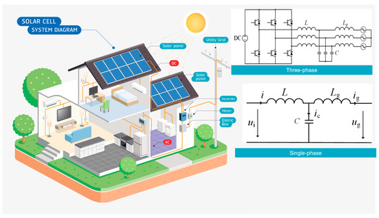
Figure 1.
L filter topology in a PV-storage system including a three-phase or single-phase schematic.
In the figure, ui represents the inverter-side voltage, ug represents the grid-side voltage, i represents the inverter-side current, ig represents the grid-side current, and L is the filter inductance. Consequently, the transfer function from the inverter-side voltage to the grid-side current for the L-type filter is derived as follows [23]:
Figure 2 shows the Bode plot of the L-filter with different inductor values. As seen from the figure, the L-filter has limited capability to attenuate low- and mid-frequency harmonics. Additionally, the larger the inductor value, the greater the harmonic attenuation across the entire frequency range. Therefore, if a higher level of harmonic attenuation on the grid side is required, a sufficiently large inductor must be used. However, increasing the inductance inevitably results in an increase in the overall size and cost of the photovoltaic inverter, while also causing a greater voltage drop across the L-filter, which complicates the control of the DC bus voltage [24]. As a result, the L-filter is suitable only for applications where the cost and size requirements for the inverter are not stringent.
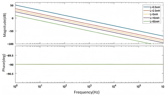
Figure 2.
Bode plots of L-type filtering at different given inductance values.
The Bode plots of LC-type filters show the relationship between the frequency of input signals and the system’s magnitude and phase response. By adjusting the inductance and capacitance, we observe how the resonance frequency of the LC filter changes and how the system’s attenuation characteristics differ from the L-type filters, particularly at higher frequencies. In this paper, we also examine how the LC filter’s phase margin and bandwidth affect the overall system stability and performance in photovoltaic-storage systems. This analysis further supports the paper’s discussion by providing a more comprehensive view of filter performance in real-world applications. We conclude that while L-type filters offer simpler designs with low costs and easy implementation, LC-type filters may provide better performance in certain applications where high-frequency noise attenuation and improved system stability are paramount. As shown in Figure 3, the LC filter for the three-phase grid-connected inverter consists of an inductor and a capacitor. The inductor is connected in series between the inverter bridge and the grid, while the capacitor is connected in parallel between different phases [25,26]. For ease of analysis and calculation, it can be simplified into the single-phase equivalent structure shown in Figure 3 [27].
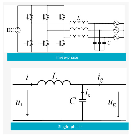
Figure 3.
LC filter topology in a PV-storage system including a three-phase or single-phase schematic.
L is the filter inductance and C is the filter capacitance. Consequently, the transfer function from the inverter-side voltage to the grid-side current for the LC filter can be expressed as shown in equation.
By combining Equation (2) with Figure 3, it can be observed that the introduction of capacitance C allows the LC inverter to operate both in grid-connected and off-grid modes. When connected to the grid, the system operates in grid-connected mode; when disconnected from the grid, it switches to off-grid mode, which is considered a key feature of the LC filter. By comparing Equations (1) and (2), it is evident that the LC filter shares the same transfer function as the L filter. In terms of harmonic filtering capability for grid-side current output from the photovoltaic inverter, and ignoring the grid’s inherent impedance, the filtering characteristics of the LC filter are very similar to those of the L filter, and, therefore, will not be elaborated here. However, the impedance of large three-phase grids is typically inductive and cannot be ignored, in which case the grid-side can be treated as having an additional inductor in series with the LC filter, forming an approximation of the LCL filter, which will be discussed later.
Although the LCL filter exhibits better attenuation of high-order harmonics, the additional equivalent grid-side inductance is not fixed, and variations in the values of the LC filter’s capacitance and inductance, as well as disturbances from the connected loads, can significantly affect the dynamic and static characteristics of the filter. Given these factors, the LC filter is typically applied in off-grid photovoltaic inverters and is therefore not considered within the scope of this paper. Given these factors, the LC filter is typically applied in off-grid photovoltaic inverters, particularly in applications where high-frequency noise attenuation is crucial. However, in grid-connected photovoltaic-storage systems, L-type filters are more commonly employed due to their simpler design and lower cost. For the purposes of this paper, we focus on the analysis of L-type filters, but acknowledge that other filter configurations, including LC filters, may also be applicable depending on the system’s specific requirements.
As shown in Figure 4, the LCL filter for the three-phase grid-connected inverter consists of an inverter-side filter inductor, a grid-side filter inductor, and a capacitor. Both inductors are connected in a series between the inverter bridge and the grid, while the capacitor is connected in parallel between the inductors of different phases. For ease of analysis and calculation, the system can be simplified into the single-phase equivalent structure shown in Figure 4.
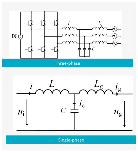
Figure 4.
LCL filter topology in a PV-storage system including a three-phase or single-phase schematic.
L represents the inverter-side filter inductance, Lf represents the grid-side filter inductance, and C is the filter capacitance. Consequently, the transfer function from the inverter-side voltage to the grid-side current for the LCL filter can be derived as follows:
The system has a pair of conjugate purely imaginary roots:
The resonant frequency of the LCL filter is calculated from the following equation:
By substituting Equations (4) and (5) into Equation (3), the following is obtained:
To illustrate the differing filtering characteristics between the LCL filter and the L filter, a comparison of the Bode plots of their transfer functions is presented in Figure 5. Both filters have the same total inductance, with specific parameter values shown in Table 1. From Equation (6) and Figure 5, it can be observed that in the low- and mid-frequency range, significantly lower than the resonance frequency of the LCL filter, the transfer functions of the LCL and L filters converge, with both displaying a slope of −20 dB/Dec. However, in the mid- to high-frequency range, far beyond the resonance frequency, there is a marked difference in the amplitude-frequency characteristics between the two filters: the L filter continues to attenuate at a rate of −20 dB/Dec, exhibiting the behavior of a first-order integrator, while the LCL filter attenuates at a rate of −60 dB/Dec, demonstrating the behavior of a third-order differentiator. Therefore, with a fixed total inductance, the LCL filter offers superior high-frequency harmonic attenuation, resulting in better filtering performance, lower production costs, and a more compact size. This makes the LCL filter a preferred choice for filtering in grid-connected photovoltaic inverters [28].
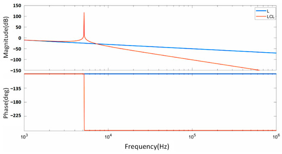
Figure 5.
Comparison of Bode plots of L and LCL filter transfer functions.

Table 1.
L and LCL filter test parameter selection.
Grid impedance variability is a critical factor influencing the resonance behavior of LCL filters, particularly in weak-grid environments where impedance fluctuations can significantly alter system dynamics. As grid impedance increases, the resonance frequency of the LCL filter shifts downward, potentially leading to increased harmonic amplification if not properly damped. Prior studies [29] have demonstrated that weak grid conditions exacerbate resonance effects, necessitating a robust damping approach. While additional simulations are not presented in this study, the proposed capacitor-branch series resistor damping strategy remains adaptable to a wide range of grid impedance variations by appropriately tuning resistance values. This ensures system stability and effective resonance suppression under diverse grid conditions.
LCL filters play a crucial role in grid-connected PV-storage systems due to their superior harmonic attenuation and ability to enhance power quality. Compared to traditional L and LC filters, LCL filters offer significantly improved suppression of high-frequency harmonics, particularly those generated by power electronic converters. Their multi-stage topology enables effective filtering while reducing the total inductance required, which in turn minimizes power losses and voltage drops across the filter. This characteristic enhances the efficiency of power conversion in PV-storage systems, ensuring compliance with stringent grid codes and reducing electromagnetic interference. Additionally, LCL filters contribute to a smoother inverter output waveform as they effectively mitigate switching-induced distortions and improve current ripple control. These attributes make LCL filters a preferred choice for maintaining grid stability while supporting the growing integration of renewable energy sources.
Beyond their harmonic suppression capabilities, LCL filters also exhibit advantages in dynamic response and operational flexibility. By efficiently controlling high-frequency oscillations, they improve system stability and reduce the risk of grid-induced instabilities, making them particularly beneficial for weak grid conditions where voltage fluctuations and impedance variations pose significant challenges. Their modular design allows for adaptable configurations, enabling optimized performance across varying operational scenarios. However, despite these advantages, LCL filters are inherently susceptible to resonance effects, which can lead to amplified oscillations, degraded system performance, and potential instability. In particular, resonance peaks and 180° phase shifts at specific frequencies present critical challenges for system reliability. Therefore, achieving an optimal balance between filtering performance and system stability necessitates the development of advanced damping strategies to mitigate these resonance issues while preserving the benefits of LCL filters in PV-storage applications.
3. Passive Damping Optimization Scheme for LCL Filter
The design of the LCL filter, in addition to meeting the grid-side filtering characteristics, must also ensure that the active and reactive power output during steady-state operation meets certain requirements. The total inductance of the LCL filter (L + Lg) should be subject to certain constraints. Under steady-state conditions, the inverter-side inductance and grid-side inductance of the LCL filter can be equivalently represented as a single inductance of (L + Lg). Figure 6 illustrates the vector relationships on the AC side of the grid-connected photovoltaic inverter.
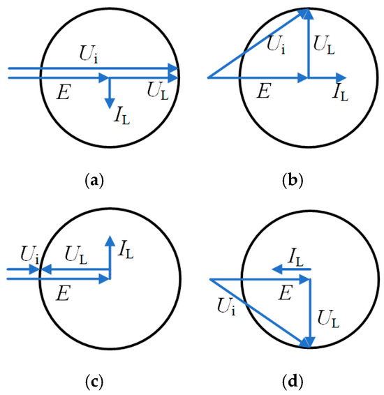
Figure 6.
Steady-state operation vector diagram of inverter AC side. (a) Pure inductive mode with the strictest inductance constraints. (b) Pure capacitive mode with relaxed inductance constraints. (c) General inverter operation showing voltage and current relationships. (d) Vector epresentation of grid-side voltage under steady-state conditions.
In the figure, Ui represents the inverter-side voltage vector, IL represents the inductor current vector, UL represents the inductor voltage vector, and E represents the grid-side voltage vector. It can be observed that, with E remaining constant, different inverter output voltages and inductance parameters correspond to different inverter states. When the grid-connected photovoltaic inverter operates in a pure inductive mode (as shown in Figure 6a), the design upper limit of the total inductance is the most stringent. In contrast, when the inverter operates in a pure capacitive mode (as shown in Figure 6b), the design upper limit for the total inductance is the most relaxed. Considering the most stringent case, if SVPWM control is applied, the total inductance (L + Lg) must satisfy the following:
In this equation, EP represents the peak value of the grid-side voltage, IP represents the peak value of the grid-side current, and Udc represents the DC bus voltage. In the process of grid-connected photovoltaic systems, the power loss of the LCL filter components, the switching stress of the switching devices, and the control of the grid-connected photovoltaic inverter are all affected by the magnitude of the inverter-side current ripple. The larger the current ripple, the worse the performance of these three factors, thus the inverter-side output current ripple must be limited.
If the DC bus voltage and the inverter switching frequency remain constant, the maximum value of the current ripple is inversely proportional to the inverter-side inductance. Therefore, the bridge-side inductance must meet the following constraint:
where fsw represents the inverter switching frequency, I1 represents the RMS value of the rated output current, and BLi is the ratio of the maximum current ripple to the RMS value of the rated output current. It is worth noting that, due to considerations of cost and inverter size, the inverter-side inductance should not be too large; however, taking into account potential calculation errors, a certain margin should be reserved in the selection of inductance. After initially selecting the inverter-side inductance L, and considering the design limitations of the grid-side inductance Lg, the value of Lg can be set as follows:
γ represents the grid-side inductance ratio coefficient, which is determined as follows:
where ig(hsw) and i(hsw) represent the hth harmonic current on the grid side and the hth harmonic current on the inverter bridge side, respectively. When calculating parameters, the ratio between these two can initially be selected as 0.2. x represents the ratio of the reactive power absorbed by the filter capacitor to the system power, typically x ≤ 0.05, with x = 0.025 often chosen as the initial value for parameter calculations. fsw and fn are the inverter switching frequency and the grid fundamental frequency, respectively. Pn is the rated power of the grid-connected inverter, and En is the RMS value of the grid’s rated voltage.
In the LCL filter of a grid-connected photovoltaic inverter, the larger the filter capacitance, the more reactive power is generated, which reduces the inverter’s power conversion capacity. Therefore, the reactive power generated by the filter capacitor in the LCL filter should be limited and generally should not exceed 5% of the rated power of the photovoltaic grid-connected system. Uc represents the capacitor voltage. Since the voltage drop across the grid-side inductance is typically small, Uc can be approximated as the grid voltage En, and thus
Finally, it is necessary to calculate the passive damping resistor Rd. According to Equation (13), designing a larger damping resistor value can effectively suppress the resonance peak but inevitably results in higher power losses. In engineering practice, the design of the damping resistor requires a trade-off between resonance peak suppression and loss reduction. Based on the energy loss model (i.e., the ratio of the energy absorbed using the damping resistor to the total power of the system), the value is typically set to one-third of the capacitive reactance of the filter capacitor at the resonant corner frequency.
It is worth noting that the LCL filter exhibits a pronounced resonance point, where its frequency response shows a resonance peak accompanied by a 180° phase shift. From a control perspective, this shift is a single negative crossing, which will generate a pair of closed-loop poles in the right half-plane, leading to instability in the grid-connected inverter [30]. The primary cause of pronounced resonance in the LCL filter is the low damping of the filter network [31]; therefore, it is necessary to discuss the introduction of damping strategies for the LCL filter.
Passive damping, which involves introducing resistors to modify the hardware structure of the filter, and active damping, which improves the grid-connected control strategy. Generally, resistors absorb active power, so adding resistors in a non-damped system results in power losses. Although active damping does not incur additional power waste, its control algorithms are complex and require additional current or voltage sensors, which can have certain negative effects on the system’s reliability and robustness [32] and increase the overall cost of the photovoltaic grid-connected system. Passive damping typically involves series or parallel resistors with the filter inductor or capacitor, making it simple, cost-effective, and therefore widely adopted in practical engineering applications.
Based on the placement of the resistors, passive damping schemes can be broadly categorized into four types: grid-side inductance series resistor, grid-side inductance parallel resistor, capacitor branch series resistor, and capacitor branch parallel resistor, corresponding to R1, R2, R3, and R4 in Figure 7.
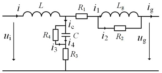
Figure 7.
LCL filter passive damping scheme topology.
As shown in Table 2, each passive damping solution has specific advantages and limitations depending on the resonance characteristics and operational conditions of the system. The series resistor is simple and cost-effective but is not ideal for high-frequency noise. On the other hand, the shunt and parallel resistors provide better damping for mid- and high frequencies, but they can lead to additional losses in the system. The resistor in the resonant tank offers the most balanced solution, providing efficient damping across a wider range of frequencies, but it is more complex and costly to implement.
Table 2.
Various filter selection and advantages.
The practical implementation of passive damping strategies in LCL-filtered grid-connected PV-storage systems involves several hardware challenges that can influence overall system performance and stability. One of the key considerations is sensor accuracy, particularly in current and voltage measurement. The effectiveness of passive damping relies on precise monitoring of system variables to ensure resonance suppression and stable operation. However, sensor errors, such as offset drift and noise, can introduce deviations in control parameters, potentially affecting system response and performance. Implementing high-precision sensors with proper calibration and compensation techniques is essential to mitigate these effects.
Another important challenge is real-time control delay in grid-connected inverters. Although passive damping does not rely on active feedback loops, its effectiveness is closely linked to the inverter’s control system. Any delay in signal processing, particularly in digital controllers, can lead to unintended phase shifts and affect the system’s transient response. Optimizing controller sampling rates and employing low-latency signal processing algorithms can help minimize these adverse effects.
Additionally, resistor heat dissipation poses a significant concern in passive damping implementation. The energy dissipated in damping resistors leads to thermal stress, which can impact the long-term reliability of components. Without adequate heat management, excessive temperatures can degrade resistor performance and introduce variations in damping effectiveness. To address this, proper resistor selection, thermal modeling, and heat dissipation strategies (such as heat sinks or forced cooling) must be incorporated into the design to ensure operational stability over extended periods.
By carefully addressing these hardware-level constraints, the proposed damping strategy can be effectively integrated into practical PV-storage systems while maintaining its intended resonance suppression and stability enhancement benefits.
4. Results and Discussion
When using the grid-side inductance series resistor scheme, where R1 ≠ 0, R2 = ∞, R3 = 0, and R4 = ∞, the transfer function of the LCL filter is as shown in the figure below (Figure 8).
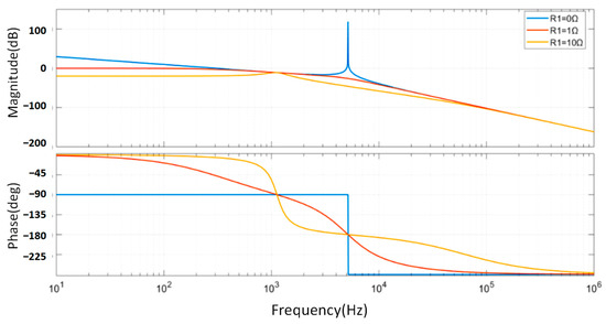
Figure 8.
Bode plot of grid-side inductor series resistance transfer function. Bode plot of the transfer function for the grid-side inductor series resistance.
Clearly, the grid-side inductance series resistor reduces the low-frequency gain of the LCL filter. In the figure, R1 = 0 represents the undamped LCL configuration. In terms of resonance characteristics, without the damping resistor, the transfer function exhibits a pronounced resonance peak; as the damping resistance increases, the degree of resonance attenuation also increases, though power loss due to the damping resistor rises correspondingly.
From the high-frequency transfer characteristics, the three curves largely overlap, indicating that introducing a series damping resistor with the grid-side inductance does not affect the high-frequency filtering performance of the filter. For the low-frequency transfer characteristics, a larger damping resistor results in lower low-frequency gain, as the inductive reactance is minimal in this range, and the series resistor increases the impedance of the inductive branch, thereby reducing the transfer ratio of the bridge-side voltage to the grid-side current, which in turn impacts the system’s control performance.
Considering the above, the grid-side inductance series resistor scheme does not simultaneously satisfy the requirements for resonance peak attenuation and low-pass filtering capability and may result in significant power loss. Therefore, the grid-side inductance series resistor is not the optimal solution.
As shown in Figure 9, the grid-side inductance parallel resistor weakens the high-frequency attenuation capability of the LCL filter. In the legend, R2 = ∞ represents the undamped LCL configuration. Regarding resonance characteristics, without the damping resistor, the transfer function exhibits a pronounced resonance peak; as the impedance of the damping branch decreases, the degree of resonance attenuation increases.
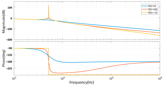
Figure 9.
Bode plot of grid-side inductor parallel resistance transfer function.
From the low-frequency transfer characteristics, the three curves are nearly identical, indicating that adding a parallel damping resistor to the grid-side inductance does not significantly alter the low-frequency attenuation characteristics. For high-frequency transfer characteristics, the smaller the damping resistor, the lower the high-frequency attenuation capability in Figure 9. This occurs because, at high frequencies, the inductive reactance is large, and the parallel resistor reduces the impedance of the inductive branch, which leads to a decrease in high-frequency harmonic filtering capability, thereby impacting system control performance.
Considering the above, the grid-side inductance parallel resistor scheme cannot balance the requirements for resonance peak attenuation and high-frequency harmonic attenuation, making it challenging to apply in practical engineering contexts.
From Figure 10, it can be observed that the capacitor branch series resistor weakens the high-frequency attenuation capability of the LCL filter. In the figure, R3 = 0 represents the undamped LCL configuration. In terms of resonance characteristics, without a damping resistor, the transfer function shows a pronounced resonance peak; after introducing damping, the higher the resistance in the damping branch, the greater the resonance attenuation. However, a small damping resistor value can already achieve a noticeable damping effect (e.g., R3 = 0.25 Ω in the figure).
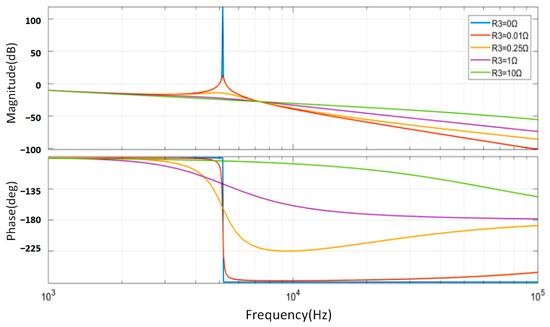
Figure 10.
Bode plot of capacitor branch series resistance transfer function.
The three curves are nearly identical in the low-frequency range, indicating that adding a series damping resistor to the capacitor branch does not significantly alter the low-frequency attenuation characteristics. For high-frequency transfer characteristics, a larger damping resistor reduces high-frequency attenuation capability, as the large inductive reactance at high frequencies and the parallel resistor lower the impedance of the inductive branch, reducing high-frequency harmonic filtering and impacting system control performance. However, when using a smaller damping resistor, high-frequency filtering performance is not significantly affected.
Considering the above, adding a small resistor to the series with a capacitor branch can balance the requirements for suppressing resonance peaks and attenuating high-frequency components in the LCL filter, making this scheme feasible (R1 = 0, R2 = ∞, R3 ≠ 0, R4 = ∞).
As shown in Figure 11, the capacitor branch parallel resistor scheme is characterized by its ability to effectively suppress resonance peaks in the mid-frequency range while maintaining the filtering characteristics in both low- and high-frequency ranges. As the damping resistance decreases, the attenuation of the resonance peak correspondingly increases. Therefore, from the perspective of full-frequency transfer characteristics, using a smaller parallel resistor can achieve excellent filtering performance. However, due to the minimal voltage drop across the grid-side inductance, the capacitor voltage is very close to the grid voltage; with the damping resistor connected in parallel across the capacitor, a decrease in resistance value would lead to increased power loss, rendering the capacitor branch parallel resistor scheme impractical (R1 = 0, R2 = ∞, R3 = 0, R4 ≠ ∞).

Figure 11.
Bode plot of transfer function of capacitor branch parallel resistor.
In real-world photovoltaic systems, dynamic weather conditions such as fluctuating solar irradiance and temperature variations impact the inverter’s operating characteristics, which in turn affect the impedance of the LCL filter. Sudden changes in irradiance can lead to transient fluctuations in inverter output current, influencing resonance dynamics. The existing research suggests that these fluctuations primarily affect low-frequency dynamics rather than the high-frequency resonance behavior targeted by our damping strategy. The proposed optimization approach ensures that the filter remains effective under varying environmental conditions, as its parameters are designed to accommodate a range of operating points. In summary, the filtering scheme for grid-connected photovoltaic inverters should adopt the passive damping scheme with a series resistor in the capacitor branch of the LCL filter.
These simulated waveforms show the time-domain behavior of the system under three different conditions: without a filter, with a traditional LCL filter, and with the proposed optimization scheme. The optimized system exhibits smoother and more stable voltage and current waveforms compared to the others. We also included the FFT analysis of the voltage and current waveforms. The results show a significant reduction in harmonic distortion when the passive damping optimization scheme is applied, particularly in the low-order harmonics (3rd, 5th, 7th). In comparison to traditional LCL filters, the optimized system demonstrates much better harmonic mitigation, improving the power quality of the system. These simulated results help to validate the theoretical predictions of the proposed optimization scheme and provide strong support for its potential to enhance the performance of the photovoltaic-storage systems. Three-Phase Voltage Waveform (Hypothetical Data) has been shown in Table 3.
Table 3.
Three-Phase Voltage Waveform (Hypothetical Data) without a filter.
5. Conclusions
In designing an LCL filter, it is essential to fully consider the damping performance of the filter and the impact of each parameter on its filtering characteristics. The design of the LCL filter involves multiple parameters and constraints, requiring a comprehensive consideration of resonance suppression, frequency characteristics, and power loss to ensure the stable and efficient operation of the filter in grid-connected photovoltaic inverters. The main conclusions of this paper are as follows:
(1) To address the resonance issue in LCL filters, introducing a passive damping scheme is an effective solution. The selection of passive damping schemes can be classified into four types based on the resistor placement: grid-side inductance series resistor, grid-side inductance parallel resistor, capacitor branch series resistor, and capacitor branch parallel resistor.
(2) Among these schemes, the capacitor branch series resistor is considered the most suitable choice as it meets the requirements for both resonance peak suppression and high-frequency component attenuation. In this configuration, R1 = 0, R2 = ∞, R3 ≠ 0, R4 = ∞.
(3) For parameter design, it is necessary to consider constraints on the total inductance, bridge-side inductance, grid-side inductance, capacitance, and damping resistor. The total inductance should be determined based on the operating state of the photovoltaic inverter. The capacitance value should be limited so that the reactive power it generates does not exceed 5% of the system’s rated power. The choice of damping resistor requires a balance between resonance peak suppression and power loss, typically based on the capacitive reactance at the resonance angular frequency of the filter capacitor.
Author Contributions
Conceptualization, Y.Z. and K.W.; methodology, T.W. and K.W.; software, Y.Z., T.W. and. C.S.; validation, T.W.; formal analysis, Y.Z. and C.S.; investigation, K.W.; resources, Y.Z.; data curation, C.S.; writing—original draft preparation, Y.Z., T.W. and K.W.; writing—review and editing, C.S. and K.W.; visualization, Y.Z.; supervision, K.W.; project administration, T.W.; funding acquisition, Y.Z. All authors have read and agreed to the published version of the manuscript.
Funding
This research was funded by National Natural Science Foundation of China General Project “Characterization and Multi Source Quantitative Evaluation of Non Technical Abilities in Engineering Education” grant number 71774010.
Data Availability Statement
Data are contained within the article.
Conflicts of Interest
The authors declare no conflict of interest.
References
- Zhang, Z.; Tang, S.; Sun, Y.; Wang, T.; He, C.; Li, G.; Huang, X. Optimization Analysis of Photovoltaic Power Generation Integration and Dynamic Characteristics in Micro-Grid. In Proceedings of the 2023 8th International Conference on Communication and Electronics Systems (ICCES), Coimbatore, India, 1–3 June 2023; pp. 289–293. [Google Scholar]
- Petronijevic, M.P.; Radonjic, I.; Dimitrijevic, M.; Pantić, L.; Calasan, M. Performance evaluation of single-stage photovoltaic inverters under soiling conditions. Ain Shams Eng. J. 2024, 15, 102353. [Google Scholar] [CrossRef]
- Ibrahim, N.F.; Mahmoud, M.M.; Al Thaiban, A.M.; Barnawi, A.B.; Elbarbary, Z.S.; Omar, A.I.; Abdelfattah, H. Operation of grid-connected PV system with ANN-based MPPT and an optimized LCL filter using GRG algorithm for enhanced power quality. IEEE Access 2023, 11, 106859–106876. [Google Scholar] [CrossRef]
- Yang, D.; Ruan, X.; Wu, H. Impedance shaping of the grid-connected inverter with LCL filter to improve its adaptability to the weak grid condition. IEEE Trans. Power Electron. 2014, 29, 5795–5805. [Google Scholar] [CrossRef]
- Ruan, X.; Wang, X.; Pan, D.; Yang, D.; Li, W.; Bao, C. Control Techniques for LCL-Type Grid-Connected Inverters; Springer: Berlin/Heidelberg, Germany, 2018. [Google Scholar]
- Sang, W.; Guo, W.; Xu, G.; Wei, T.; Shi, C.; Liu, Z.; Xue, H.; He, Z.; Li, J.; Shen, J. A novel robust active damping control strategy based on H∞ loop shaping for the grid-tied LCL inverter. Front. Energy Res. 2024, 12, 1473060. [Google Scholar] [CrossRef]
- Liu, Y.; See, K.-Y.; Yin, S.; Simanjorang, R.; Tong, C.F.; Nawawi, A.; Lai, J.-S.J. LCL filter design of a 50-kW 60-kHz SiC inverter with size and thermal considerations for aerospace applications. IEEE Trans. Ind. Electron. 2017, 64, 8321–8333. [Google Scholar] [CrossRef]
- Tang, Y.; Loh, P.C.; Wang, P.; Choo, F.H.; Gao, F. Exploring inherent damping characteristic of LCL-filters for three-phase grid-connected voltage source inverters. IEEE Trans. Power Electron. 2011, 27, 1433–1443. [Google Scholar] [CrossRef]
- Zhu, D.; Zou, X.; Zhao, Y.; Peng, T.; Zhou, S.; Kang, Y. Systematic controller design for digitally controlled LCL-type grid-connected inverter with grid-current-feedback active damping. Int. J. Electr. Power Energy Syst. 2019, 110, 642–652. [Google Scholar] [CrossRef]
- Fang, J.; Li, X.; Yang, X.; Tang, Y. An integrated trap-LCL filter with reduced current harmonics for grid-connected converters under weak grid conditions. IEEE Trans. Power Electron. 2017, 32, 8446–8457. [Google Scholar] [CrossRef]
- Ma, K.; Tang, W.; Cheng, R.; Song, Y. Modeling of interconnected voltage and current controlled converters with coupled LC–LCL filters. IEEE Trans. Power Electron. 2020, 36, 3995–4005. [Google Scholar] [CrossRef]
- Jackson, R.; Zulkifli, S.A.; Salimin, S. A Sequence-Rule Analysis of Active and Passive LCL Filters for Three-Phase Inverter-Grid Connection for Damping Stability Consideration. Int. J. Renew. Energy Res. 2020, 10, 1545–1553. [Google Scholar]
- Büyük, M.; Tan, A.; Tümay, M.; Bayındır, K.Ç. Topologies, generalized designs, passive and active damping methods of switching ripple filters for voltage source inverter: A comprehensive review. Renew. Sustain. Energy Rev. 2016, 62, 46–69. [Google Scholar] [CrossRef]
- Yao, W.; Yang, Y.; Xu, Y.; Blaabjerg, F.; Liu, S.; Wilson, G. Phase reshaping via all-pass filters for robust LCL-filter active damping. IEEE Trans. Power Electron. 2019, 35, 3114–3126. [Google Scholar] [CrossRef]
- Ma, G.; Xie, C.; Li, C.; Zou, J.; Guerrero, J.M. Passivity-based design of passive damping for LCL-type grid-connected inverters to achieve full-frequency passive output admittance. IEEE Trans. Power Electron. 2023, 38, 16048–16060. [Google Scholar] [CrossRef]
- Wu, T.-F.; Misra, M.; Lin, L.-C.; Hsu, C.-W. An improved resonant frequency based systematic LCL filter design method for grid-connected inverter. IEEE Trans. Ind. Electron. 2017, 64, 6412–6421. [Google Scholar] [CrossRef]
- Lei, Y.; Xu, W.; Mu, C.; Zhao, Z.; Li, H.; Li, Z. New hybrid damping strategy for grid-connected photovoltaic inverter with LCL filter. IEEE Trans. Appl. Supercond. 2014, 24, 1–8. [Google Scholar] [CrossRef]
- Zou, B. Active Damping of LCL Filter Resonance for a Single Phase Grid-Connected Distributed Power Generation System; Queen’s University (Canada): Kingston, ON, Canada, 2014. [Google Scholar]
- Cengiz, M.; Duman, T. Design and analysis of L and LCL filters for grid-connected HNPC inverters used in renewable energy systems. Balk. J. Electr. Comput. Eng. 2024, 12, 53–61. [Google Scholar] [CrossRef]
- Hernández-Callejo, L.; Gallardo-Saavedra, S.; Alonso-Gómez, V. A review of photovoltaic systems: Design, operation and maintenance. Sol. Energy 2019, 188, 426–440. [Google Scholar] [CrossRef]
- Rajamallaiah, A.; Karri, S.P.K.; Alghaythi, M.L.; Alshammari, M.S. Deep reinforcement learning based control of a grid connected inverter with LCL-filter for renewable solar applications. IEEE Access 2024, 12, 22278–22295. [Google Scholar] [CrossRef]
- Gu, Y.; Green, T.C. Power system stability with a high penetration of inverter-based resources. Proc. IEEE 2022, 111, 832–853. [Google Scholar] [CrossRef]
- Zhou, X.; Zhou, L.; Chen, Y.; Shuai, Z.; Guerrero, J.M.; Luo, A.; Wu, W.; Yang, L. Robust grid-current-feedback resonance suppression method for LCL-type grid-connected inverter connected to weak grid. IEEE J. Emerg. Sel. Top. Power Electron. 2018, 6, 2126–2137. [Google Scholar] [CrossRef]
- Jayalath, S.; Hanif, M. Generalized LCL-filter design algorithm for grid-connected voltage-source inverter. IEEE Trans. Ind. Electron. 2016, 64, 1905–1915. [Google Scholar] [CrossRef]
- Mohamed, I.S.; Rovetta, S.; Do, T.D.; Dragicević, T.; Diab, A.A.Z. A neural-network-based model predictive control of three-phase inverter with an output $ LC $ filter. IEEE Access 2019, 7, 124737–124749. [Google Scholar] [CrossRef]
- Nauman, M.; Hasan, A. Efficient implicit model-predictive control of a three-phase inverter with an output LC filter. IEEE Trans. Power Electron. 2016, 31, 6075–6078. [Google Scholar] [CrossRef]
- Fu, X.; Li, S. A novel neural network vector control for single-phase grid-connected converters with L, LC and LCL filters. Energies 2016, 9, 328. [Google Scholar] [CrossRef]
- Havrlík, M.; Libra, M.; Poulek, V.; Kouřím, P. Analysis of Output Signal Distortion of Galvanic Isolation Circuits for Monitoring the Mains Voltage Waveform. Sensors 2022, 22, 7769. [Google Scholar] [CrossRef]
- Fang, T.; Shen, S.; Zhang, L.; Jin, Y.; Huang, C. Capacitor current feedback with phase-lead compensator to eliminate resonant frequency forbidden region for LCL-type grid-connected inverter in weak grid. IEEE J. Emerg. Sel. Top. Power Electron. 2021, 9, 5581–5596. [Google Scholar] [CrossRef]
- Hossen, T.; Mirafzal, B. Hidden modes of instability for inverters in weak grids. IEEE Trans. Ind. Appl. 2023, 59, 4505–4515. [Google Scholar] [CrossRef]
- Anzalchi, A.; Moghaddami, M.; Moghaddasi, A.; Sarwat, A.I.; Rathore, A.K. A new topology of higher order power filter for single-phase grid-tied voltage-source inverters. IEEE Trans. Ind. Electron. 2016, 63, 7511–7522. [Google Scholar] [CrossRef]
- Wu, W.; Liu, Y.; He, Y.; Chung, H.S.-H.; Liserre, M.; Blaabjerg, F. Damping methods for resonances caused by LCL-filter-based current-controlled grid-tied power inverters: An overview. IEEE Trans. Ind. Electron. 2017, 64, 7402–7413. [Google Scholar] [CrossRef]
Disclaimer/Publisher’s Note: The statements, opinions and data contained in all publications are solely those of the individual author(s) and contributor(s) and not of MDPI and/or the editor(s). MDPI and/or the editor(s) disclaim responsibility for any injury to people or property resulting from any ideas, methods, instructions or products referred to in the content. |
© 2025 by the authors. Licensee MDPI, Basel, Switzerland. This article is an open access article distributed under the terms and conditions of the Creative Commons Attribution (CC BY) license (https://creativecommons.org/licenses/by/4.0/).