Article

Edge-of-Chaos Kernel and Dynamic Analysis of a Hopfield Neural Network with a Locally Active Memristor

1
School of Integrated Circuits, Anhui University, Hefei 230601, China
2
School of Electronic and Information Engineering, Anhui University, Hefei 230601, China
3
CNBM Environmental Protection Research Institute (Jiangsu) Co., Ltd., Yancheng 224051, China
*
Author to whom correspondence should be addressed.
Electronics 2025, 14(4), 766; https://doi.org/10.3390/electronics14040766
Submission received: 7 December 2024 / Revised: 24 January 2025 / Accepted: 27 January 2025 / Published: 16 February 2025

Abstract

:
Locally active memristors with an Edge-of-Chaos kernel (EOCK) represent a significant advancement in the simulation of neuromorphic dynamics. However, current research on memristors with an EOCK remains at the circuit level, without further analysis of their feasibility. In this context, we designed a memristor and installed it in a third-order circuit, where it showed local activity and stability under defined voltage and inductance parameters. This behavior ensured that by varying the input voltage and inductance, the memristor could effectively simulate various neural activities, including inhibitory postsynaptic potential and chaotic waveforms. By subsequently integrating the memristor with an EOCK into a Hopfield neural network (HNN) framework and substituting the self-coupling weight, we observed a rich spectrum of dynamic behaviors, including the rare phenomenon of antimonotonicity bubble bifurcation. Finally, we used hardware circuits to realize these generated dynamic phenomena, confirming the feasibility of the memristor. By introducing the HNN and studying its dynamic behavior and hardware circuit implementation, this study provides theoretical insights into and an empirical basis for developing circuits and systems that replicate the complexity of human brain functions. This study provides a reference for the development and application of EOCK in the future.

1. Introduction

Chaos theory, which originated in the work of Edward Lorentz in the 1960s, has become a fundamental field of nonlinear dynamics characterized by sensitivity to the initial conditions, aperiodicity, and the coexistence of determinism and randomness. These properties have led to the development of various chaotic systems, such as Lorentz, Chen, and Lu systems, each with unique dynamic behavior. Chaos theory has a wide range of applications, including secure communication [1,2], chaotic circuits [3,4], and image encryption [5,6]. For example, Feng first constructed a new fractional-order 3D Lorenz chaotic system and a 2D sinusoidally constrained polynomial hyperchaotic map (2D-SCPM) and then elaborately developed a multi-image encryption algorithm based on the new fractional-order 3D Lorenz chaotic system and 2D-SCPM (MIEA-FCSM). This algorithm generates the final ciphertext image through two rounds of scrambling and diffusion [7]. Abdullah et al. designed a fractional-order Arneodo chaotic excitation system with cubic nonlinearity and then used a singlet fractional-order sliding mode controller (FOSMC) to synchronize two fractional-order Arneodo chaotic systems with different initial conditions. A new secure communication system based on a single-chip microcomputer was designed and implemented using chaotic masking [8].
Since the concept of a memristor was first proposed by Professor Chua in 1971 [9], it has become a key element in the construction of artificial neural networks. Compared with resistors, capacitors, and inductors, memristors have catalyzed extensive exploration in countless fields due to their unique memory storage function, leading to research on applications such as neural networks [10,11,12] and chaotic circuits [13,14,15]. In terms of theory, memristors have enriched the study of complex dynamics in various systems [16,17]. Generally, memristors are divided into voltage-controlled memristors and current-controlled memristors; voltage-controlled memristors are widely used because of their significant advantages of low power consumption, high energy efficiency, and rich dynamic behavior. Zhang et al. designed a chaotic circuit for a convolutional neural network (CNN) system based on a voltage-controlled memristor [18]. Shi et al. proposed a voltage-controlled memristor with floating input for D-latch validation [19].
In recent years, the dynamic properties of memristors have attracted much attention, especially due to their interesting performance at the edge-of-chaos (EOC). The EOC is a special part of the locally active domain (LAD) [20]. A memristor located at the EOC is in a stable but unstable state, in which rich dynamic behavior is generated [21,22]. Chua solved the Turing instability and Smale phenomenon using memristors with EOC [23]. The Edge-of-Chaos kernel (EOCK) is a special part of EOC. It is a new physical concept proposed by Chua in 2022 [24], aimed at exploring the complex dynamics of circuit systems located at the threshold between order and disorder. The EOCK is a simple one-port circuit formed by connecting a negative resistance and a negative inductance. The existence of an EOCK not only solves some mathematical problems [25] but also can be used to induce periodic oscillations in oscillators [26]. The memristors with an EOCK reported in these articles can simulate rich neuromorphic behavior, so the EOCK is highly important in unlocking the mysteries of neuromorphic memristors.
Neural networks represent one of the most important fields in the application of memristors. Compared with traditional artificial neural networks, memristor-coupled neural networks provide a new direction for the study of the complex behavior of human brains because of their complex neuromorphic behavior [27,28,29]. To simulate the dynamic behavior of neurons, various neural networks and neuron models have been developed [30,31,32,33]. Hopfield neural networks (HNNs) are widely used because of their simple structure, high stability, and complexity. HNNs are often used in chaotic systems and for other complex behavior [34,35,36]. Memristor-coupled neural network chaotic systems integrate the advantages of memristors, neural networks, and chaotic systems, making them widely used in many fields, such as compression processing and data storage [37,38,39,40,41]. Yu applied an HNN with extreme multistability for video encryption [42], Kong applied an HNN with hyperchaos and multiscrolling for image encryption [43], and Ding et al. applied an HNN with multiple coexistences for medical image encryption and implemented it in hardware [44]. A memristor with an EOCK-coupled HNN will perform better in these fields because of its higher complexity.
At present, memristors without an EOCK are relatively mature at the circuit-simulation level [45]. However, research into memristors with an EOCK has just entered the circuit simulation stage, and feasibility analyses are insufficient. Therefore, this paper proposes a type of voltage-controlled memristor with an EOCK. First, the device was placed into a third-order circuit to observe the neural mentality behavior and then coupled with a neural network to study its dynamic characteristics and implement the hardware circuit. The work presented in this paper includes the following innovations and contributions:
(1)
A third-order circuit of a voltage-controlled memristor with an EOCK is proposed, which can produce a variety of different dynamic phenomena.
(2)
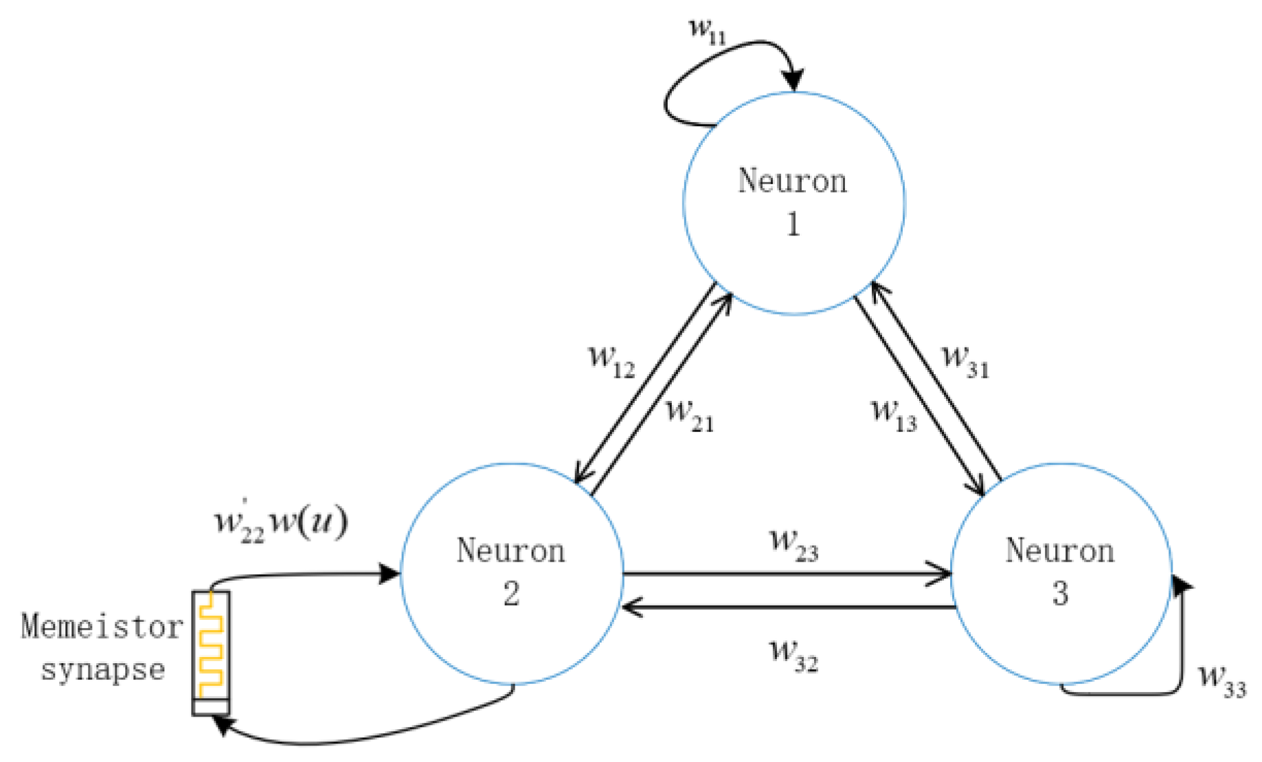
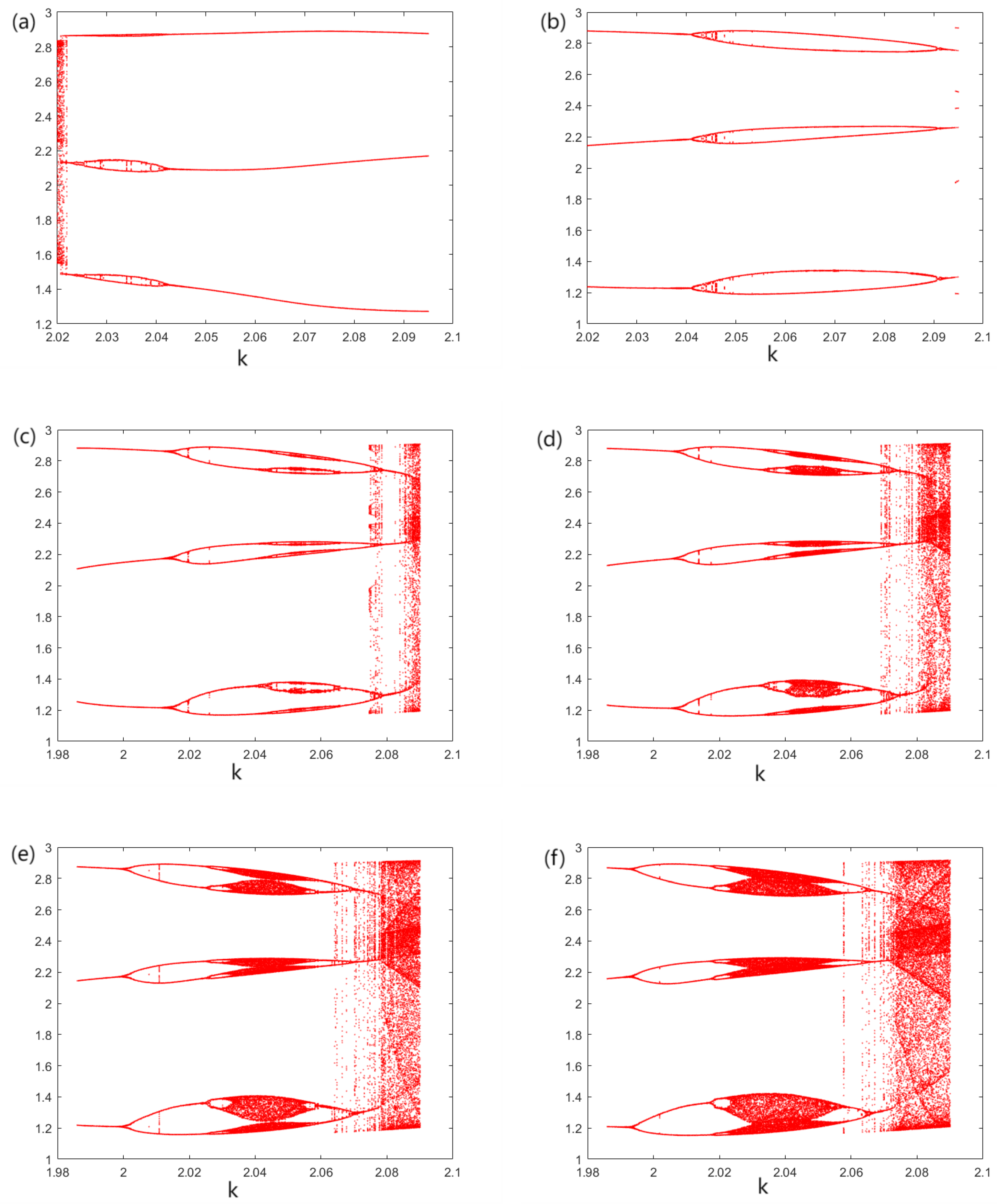
The memristor is coupled with an HNN to study the bifurcation behavior at different coupling intensities, and a rare antimonotonicity phenomenon is observed. When one variable in the coupling intensity is changed, bubble bifurcation can be observed. The feasibility is verified with an STM32 hardware board.
The rest of this article is arranged as follows: In Section 2, we design a memristor with an EOCK, analyze its tight hysteresis properties, locally active properties, and asymptotic stability, and then design a third-order memristor circuit. In Section 3, the kinetic phenomena of the memristor circuit, such as the period, chaos, damping spiking, and single-spike bursting, are analyzed. In Section 4, the memristor-coupled HNN model is proposed. The antimonotonicity and bubble bifurcation of the system are discussed by means of the Lyapunov exponent spectrum and bifurcation diagram. Then, the hardware implementation based on STM32 is described. The last part summarizes the article.

2. A Memristor Model and Memristive Circuit

Memristors are divided into voltage-controlled and current-controlled memristors. In general, a voltage-controlled memristor is defined as:
d x d t = g ( x , v M ) , i M = G ( x ) v M ,
where x, iM and vM are the state variables, i.e., the current and input voltage of the memristor; G ( x ) is the memductance function, and the function g defines the equation of the memristor. Based on Chua’s expansion theorem, a general type of a locally active memristor with an EOCK is designed, and a general type of a locally active memristor is proposed:
i M = G ( x ) v M = 0.01 x 2 v M , d y d x = g ( x , v M ) = 10 ( x 4 25 x 2 10 x v M 10 v M + 15 ) ,
where x, iM and vM are the state variable, current and input voltage of the first-order memristor. current and input voltage of the first-order memristor, respectively. This type of memristor is chosen in this study because it has rich dynamic characteristics that can be obtained, and the equations are easy to obtain.

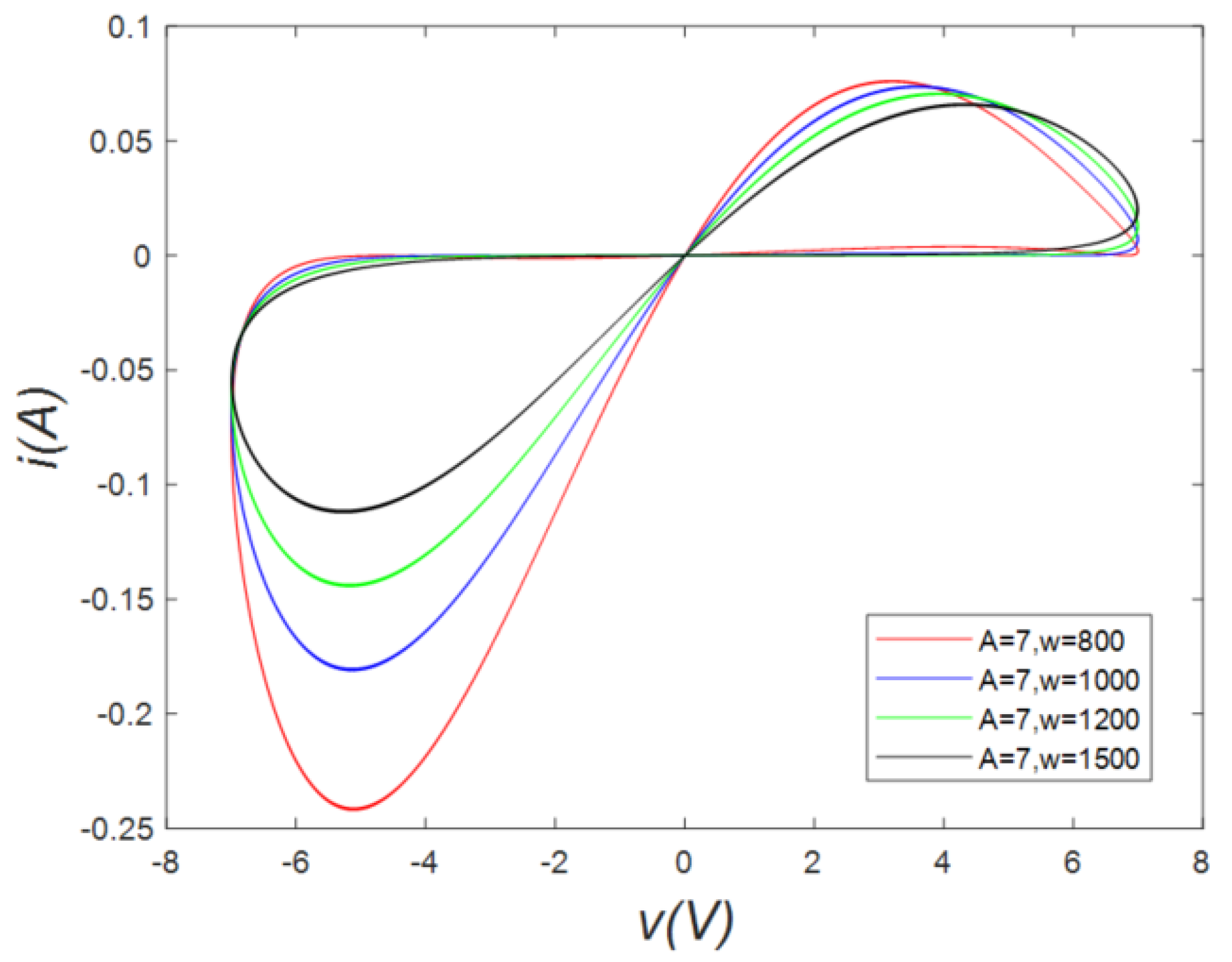
2.1. Hysteresis Loops
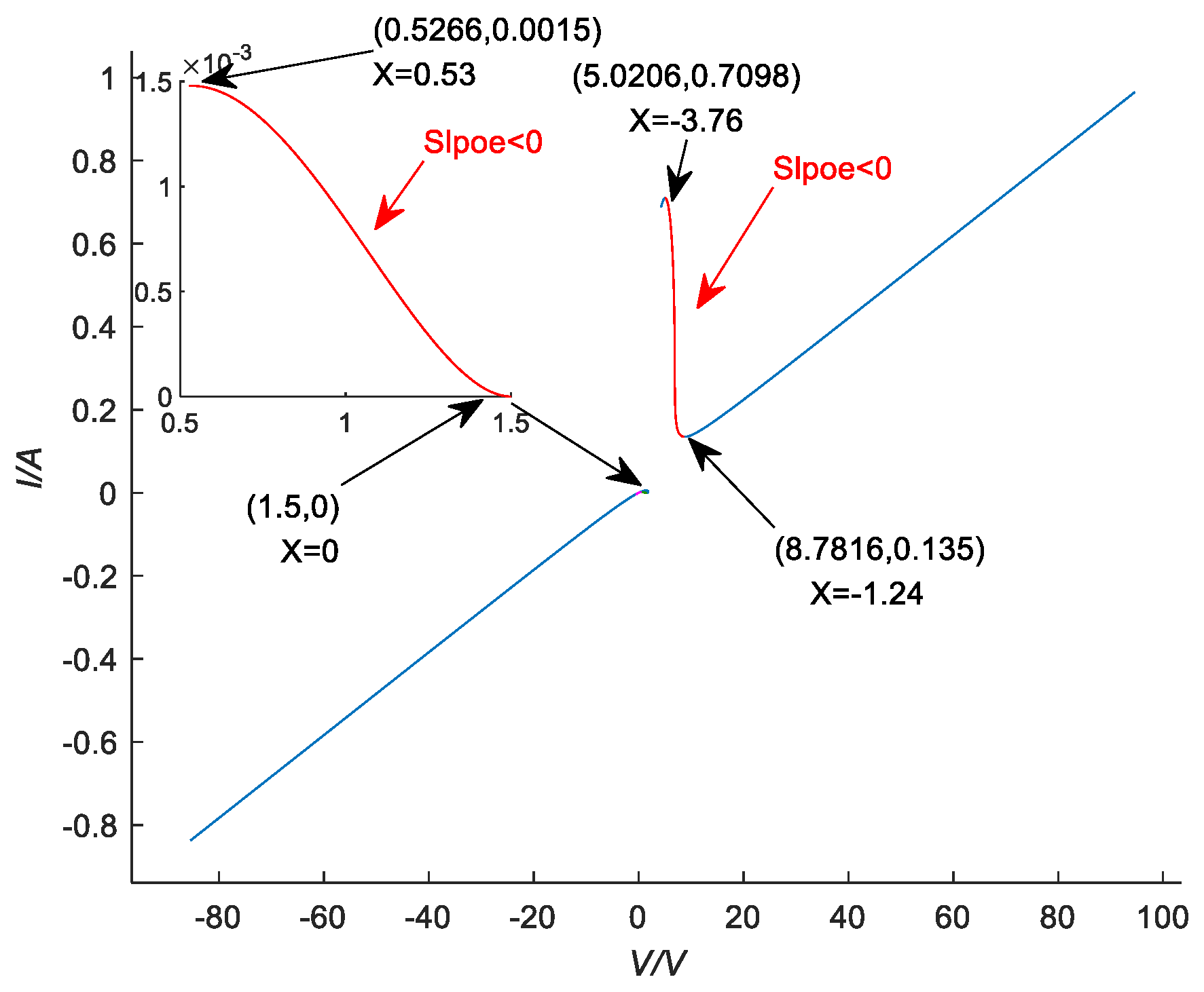
A sinusoidal voltage excitation of unit amplitude is applied to both ends of the voltage-controlled memristor used in this paper. The terminal voltage of the memristor is vM, and the current flow is i; thus, the sinusoidal voltage equation applied is
v M = A sin ( w t ) , i = G ( x ) v = 0.01 x 2 v M .
When we let A = 7 and w = 800, 1000, 1200, 1500, the ODE45 algorithm can be employed to derive the planar voltammetry characteristic curves of the voltage-controlled memristor, as illustrated in Figure 1. The voltage-current characteristics of the memristor exhibit an inclined pinched hysteresis loop shape, as depicted in Figure 1. The area enclosed by the voltage-current characteristic curve clearly progressively diminishes with increasing w, which aligns with the fundamental behavior observed in locally active memristors.

2.2. Locally Active

To more clearly and conveniently observe the region where the first-order memristor appears locally active and asymptotically stable, we draw the DC V-I curve within a voltage range of −80 V < V < 80 V as shown in Figure 2. According to Figure 2, the DC V-I curve contains two stable negative slope domains, namely, the voltage ranges of 5.0206 V < V < 8.7815 V and 0.5266 V < V < 1.5 V, which are represented by the red curve. These two parts constitute the locally active domain (LAD).

2.3. Asymptotic Stability

According to Jin’s paper [46], whether the memristor is asymptotically stable can be determined. Equation (4) is Jacobi’s equation:
J ( Q ) = J 11 J 12 J 21 J 22 Q ,
where J11, J12, J21, J22 satisfy Equation (5), and their values are the same as the first-order Taylor series expansion coefficients of the voltage-controlled memristor. A general voltage-controlled memristor with an EOCK is considered asymptotically stable when J21 < 0.
J 11 = V M G ( x ) x Q = V G ( x ) x Q , J 12 = G ( x ) v M v M Q = G ( x ) , J 21 = g ( x , v M ) v M Q , J 22 = g ( x , v M ) v M Q .
The red area in Figure 2 was analyzed for stability. Figure 3a shows that the memristor is asymptotically unstable in the range of 5.0206 V < V < 8.7815 V. As shown in Figure 3b, it is also asymptotically unstable in the range of 0.5266 V < V < 1.5 V.

2.4. Edge-of-Chaos Kernel

The EOCK is a novel physical concept introduced by Chua in 2022. It comprises a one-port circuit that integrates a negative inductor and a negative resistor connected in series. Since the negative resistance has feedback enhancement characteristics and nonlinear behavior and the negative inductance can change the stability of the circuit, even if the structure is simple, the combination of the two facilitates the production of an EOCK by the circuit, which thus exhibits complex dynamic behavior and further provides a theoretical basis for simulating complex neural network behavior. Figure 4 shows the circuit characteristics of the EOCK, defined by Chua in [24]. To test whether our defined memristor has an EOCK, only two conditions need to be satisfied:
J 21 < 0 , J 22 J 11 < 0
.

2.5. A Memristive Circuit with an EOCK

Owing to the interaction between the memristor, capacitor, and inductor, the nonlinear characteristics of the whole circuit are enhanced, the dynamic behavior of the circuit is more complicated, and the memristor circuit exhibits rich multistable phenomena and chaotic behavior. Therefore, the use of a memristor with an EOCK significantly enhances the neurodynamics in the memristor circuit. Therefore, we use a combination of memristors, capacitors, and inductors to build a third-order circuit, as shown in Figure 5. The equation of state of the third-order memristor circuit in Figure 5 is
d x d t = 10 ( x 4 25 x 2 10 v C 10 x v C + 15 ) , d v C d t = ( i L 0.01 x 2 v C ) C , d i L d t = v i n v c L ,
where x, vc, iL and vin denote the state variable of the first-order memristor, defined in (2), the voltage across capacitor C, the current through inductor L and the input voltage of the memristive circuit, respectively, x and vC are the state variables of the memristive circuit; and vout = vc denotes the output voltage of the circuit.
We calculate the V L domain of the third-order 1-port circuit, as mapped in Figure 6. The diagram maps the different parameters of the third-order memristor circuit to the V L diagram to observe the changes in the stability of the memristor in this environment. In Figure 6, the blue color represents the open right half plane (RHP), the orange color represents the edge-of-chaos (EOC) domain, and the dark green color represents the locally passive domain. The RHP and EOC domains are collectively called the LAD. Figure 6 shows where the locally active, locally passive, EOC and RHP pole domains of the memristor circuit are located at different input voltages V and inductances L .
In Figure 6a, the union of the orange domain and the blue domain is the locally active parameter set of the circuit over the voltage range of 5.0206 V < V < 8.7815 V, where the memristor is stable because its pole p = R X / L x < 0 on the open left half plane (LHP) [47]. Figure 6a shows that variations in the inductance L and voltage V change the position of the pole and the stability of the memristor circuit, thus destroying the stability of the memristor and leading to the appearance of the RHP pole domain. As a result, some of the equilibrium points of the circuit move from the EOC domain to the RHP pole domain and are no longer asymptotically stable. Notably, inductance L in the blue domain will make the memristor unstable, causing the memory circuit to oscillate. Similarly, in Figure 6b, in the union of the orange and blue domains, the memristor is locally active and stable. Figure 6b shows that inductance L in the blue domain changes the position of the pole and the stability of the memory circuit, thus destroying the stability of the memristor and causing the circuit to oscillate.
In this section, we first design a voltage-controlled memristor model and then study its tight hysteresis characteristics and local active and asymptotic stability characteristics. We analyze the mechanism of EOCK formation. Then a memristor circuit with EOCK is constructed, and L and V planes are plotted, including local active domain, RHP domain and EOC domain. Because the V L plane contains such a rich domain, it is easy to know that EOCK’s memristor oscillates due to changes in inductance and capacitance of the external environment.

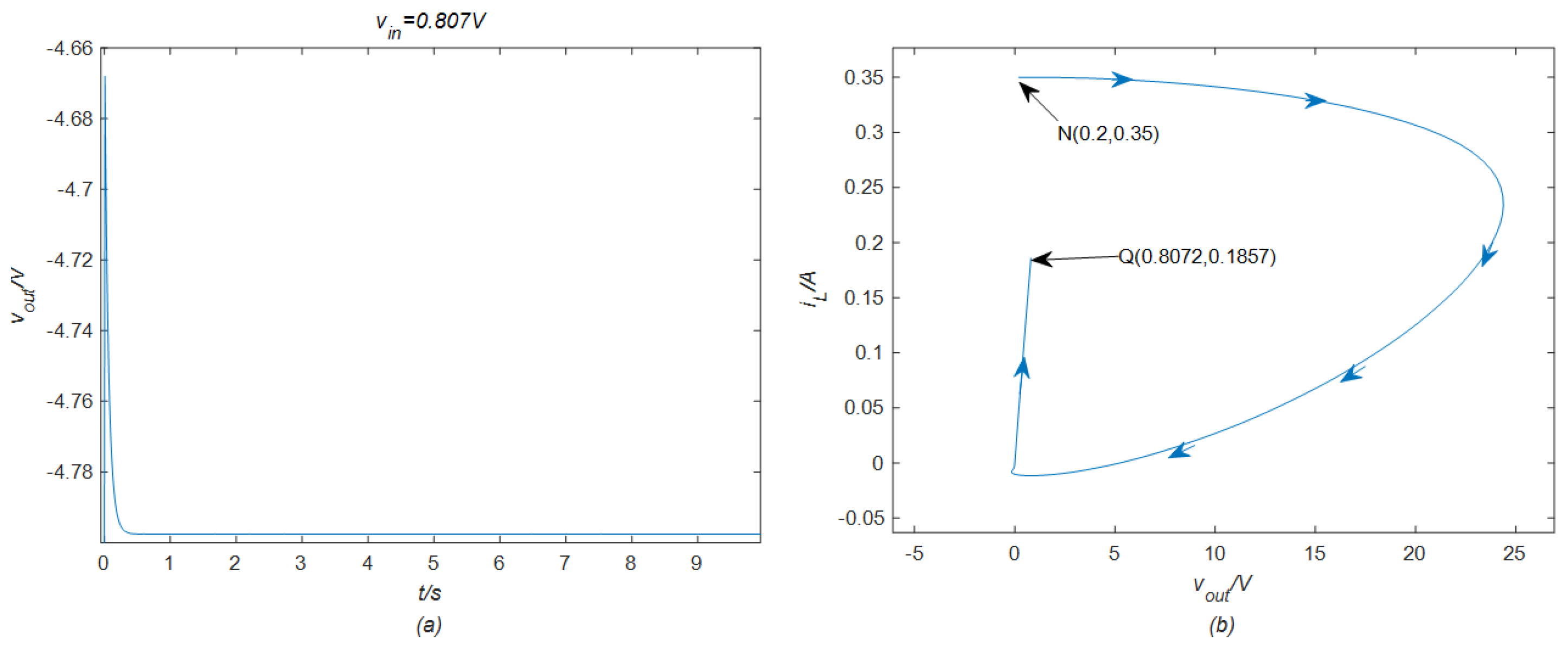
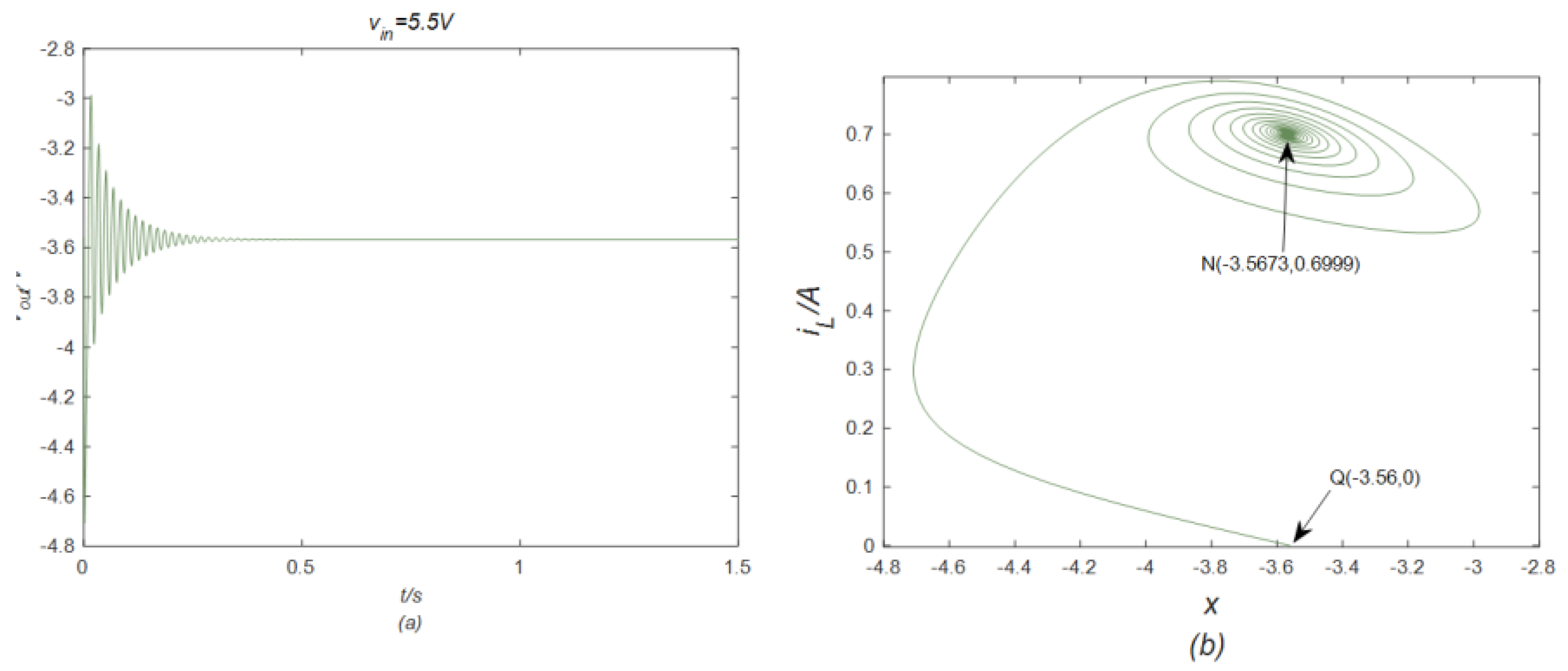
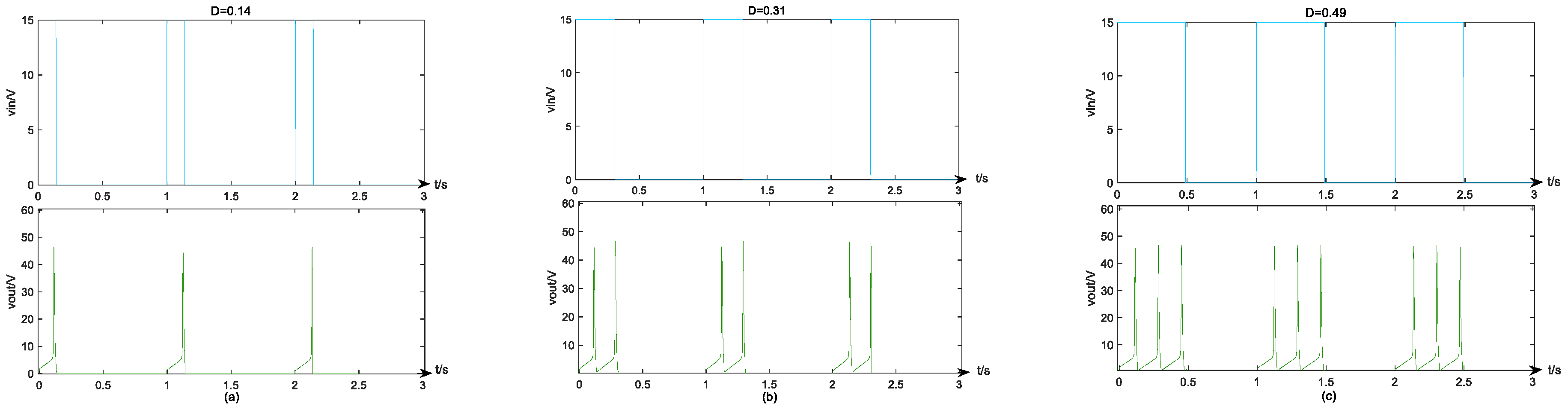
3. EOCK and Neuromorphic Behaviors

In this section, we explore the neuromorphic behavior of locally active memristors with an EOCK. We observe different neuromorphic behaviors by varying the values of the input voltage vin and the series inductance L in Figure 5. When we feed the memristor an adjustable DC input voltage, we observe some neuromorphic behavior, as shown in Figure 7, Figure 8, Figure 9 and Figure 10. For each diagram mentioned, each panel (a) in the diagram shows a time-domain waveform diagram and the neuromorphic behavior generated by the memristive circuit, and each panel (b) shows a phase orbit diagram, i.e., a two-dimensional projection of an attractor in three-dimensional space. vout = vc in Figure 7, Figure 8, Figure 9 and Figure 10.
When we adjust the value of the DC voltage vin added to the memristor circuit to 0.807V, we observe the neuromorphic behavior of phasic spiking in Figure 7a, with a pulse amplitude of −4.468 V. Figure 7b depicts a two-dimensional projection of the attractor onto vout and iL. It shows a light blue trajectory from the initial state ( x ( 0 ) , v c ( 0 ) , i L ( 0 ) ) = ( 0 , 0.2 , 0.35 ) to an asymptotically stable equilibrium point Q ( x , v o u t , i L ) = ( 4.7976 , 0.8072 , 0.1857 ) , with arrows indicating the direction of movement. When we further increase the DC input voltage from 0.807 V to 5.5 V, the memristor circuit generates a damping spike, as depicted in Figure 8a. Figure 8b shows a stable limit cycle, with a light green trajectory from the initial state ( x ( 0 ) , v c ( 0 ) , i L ( 0 ) ) = ( 3.56 , 0 , 0 ) to an asymptotically stable equilibrium point Q ( x , v o u t , i L ) = ( 3.5673 , 5.5019 , 0.6999 ) , and the arrows indicate the direction of movement. Finally, by increasing the voltage from 5.501 V to 8.72 V, a chaotic waveform can be observed, as shown in Figure 10b. The randomness of the chaotic waveform is very high. The figure shows a purple trajectory from the initial state x 0 , v c ( 0 ) , i L ( 0 ) = ( 1.24457 , 8.7 , 0.135 ) to an asymptotically stable equilibrium point Q ( x , v o u t , i L ) = ( 1.2447 , 8.732 , 0.1353 ) , with arrows indicating the direction of movement.
According to the available data, we can easily calculate the Taylor series expansion coefficients in (5) as J 11 = 0.0732 , J 21 = 1930 , and J 22 = 379 . Because J 21 < 0 and J 11 J 22 = 29.3 < 0 satisfy (6), the memristor can be judged as having an EOCK. Similarly, when J 11 = 0.3924 , J 21 = 432.1 , J 22 = 256.7 , and J 11 J 22 = 100.7 , J 21 < 0 and J 11 J 22 < 0 . When J 11 = 0.3919 , J 21 = 427.4 , J 22 = 256.2 , and J 11 J 22 = 100.4 ( J 11 = 0.217 , J 21 = 177 , J 22 = 24.4 , and J 11 J 22 = 5.317 ) at V i n = 5.501 V ( V i n = 8.72 V), J 21 < 0 ( J 21 < 0 ), and J 11 J 22 < 0 ( J 11 J 22 < 0 ). The above calculations show that the memristor circuit containing an EOCK can generate damping-spike, single-spike-burst, pulse-spike, and chaotic waveforms.
If a voltage pulse signal with pulse amplitude Um = 5.521 V, period T = 1 s, and different pulse duty cycle factors are used as the input voltage vin, we can observe periodic bursts, as shown in Figure 11. In Figure 11, the upper part shows the input voltage of the pulse signal with different pulse duty ratios; the lower part shows the neuromorphic behavior generated by the memristor circuit. When we apply the pulse signal with pulse duty cycle D = 0.14 as the input voltage vin, memristor circuit single-spike bursting is generated. When D is increased to 0.31 and 0.49, two-spike bursting and three-spike bursting occur, respectively. Figure 11 shows that the peak number can be changed by adjusting the pulse duty cycle D of the pulse signal. Therefore, we can use the pulse duty factor of the input voltage to control the neuromorphic behavior of the memory circuit. In addition, the memristor can be easily calculated as having an EOCK when Vin = 5.521 V.
This section vividly demonstrates the rich neuromorphic behavior of a memristor with an EOCK by using intuitive images so that we can more easily and quickly gain insight into the close and inseparable connection between the EOCK and neuromorphic behavior. The results further confirm the great potential and feasibility of using memristors containing an EOCK in the field of simulating neuronal neuromorphic behavior.

4. Proposed HNN and Its Hardware Implementation

4.1. The Dynamical Behavior of the HNN Model

To verify that the memristor model with an EOCK presented in this paper is rich and can possibly be applied in practice in the future, we put it into a carefully selected HNN to observe its characteristics. This study leverages the HNN model presented in [48], which comprises three interconnected neurons. The connectivity pattern of this network is delineated in Figure 12. Within the context of HNN systems, the self-coupling mechanism of the second neuron is augmented by incorporating a memristor with an EOCK, as defined in the current study, thereby replacing the conventional connection weight. The circuit equation of the HNN we are referencing is:
C i d x i d t = x i R i + j = 1 n w i j tanh ( x j ) + I i .
In this work, we set Ci = 1, Ri = 1, Ii = 0, and n = 0. In the analog computer implementation of the HNN, the synaptic weight wij is a resistance. Starting from the general connection topology, the synaptic weight matrix expression is as follows:
W = w 11 w 12 w 13 w 21 w 22 w 23 w 31 w 32 w 33 = 2.3 1.2 0.5 2 w 2 w φ 1.15 5 0 1 .
In summary, the smooth nonlinear fourth-order differential equation describing the proposed memory HNN can be expressed as:
x . 1 = x 1 + 2.3 tanh ( x 1 ) 1.2 tanh ( x 2 ) + 0.5 tanh ( x 3 ) , x . 2 = x 2 + 2 tanh ( x 1 ) + w 2 w ( x 4 ) tanh ( x 2 ) + 1.15 tanh ( x 3 ) , x . 3 = x 3 5 tanh ( x 1 ) tanh ( x 3 ) , x . 4 = 10 ( x 4 4 25 x 4 2 + 15 10 tanh ( x 2 ) 10 tanh ( x 2 ) x 4 .
In the connection topology shown in Figure 12, the HNN model includes three state variables. However, the state equation represented by (9) involves four variables, with the fourth variable being related to the memory self-synaptic connection of the second state variable, which reflects the memory of the synaptic weight of the second neuron. Additionally, w 2 w ( x 4 ) = w 2 ( a b tanh ( x 4 ) ) represents the self-synaptic weight w 22 of the second neuron, where w 2 , a, and b are positive parameters associated with the memory synaptic weight w φ .

4.2. Dynamical Behavior Analysis

Based on (7) and (8), the dynamics of the HNN function parameters and memristor coupling strength are studied in this section by using the MATLAB2023 ODE45 algorithm. With the step size fixed at t = 0.01, the single-parameter bifurcation diagram and the Lyapunov exponent spectrum are drawn. The Lyapunov exponent spectrum is calculated using Wolff’s method with a time length of 800. The bifurcation and the Lyapunov exponent spectrum with initial conditions 0.1 , 1 , 1 , 0.1 and 0.1 , 1 , 1 , 0.1 are drawn.
According to the formula w 2 w ( x 4 ) = w 2 ( a b tanh ( x 4 ) ) , there are three variable parameters. To analyze the dynamic behavior of w 2 , a and b, we numerically calculate the single-parameter bifurcation plot and the Lyapunov exponent spectrum. When w 2 is fixed at 1.5 and a is fixed at 1, the single-parameter bifurcation plot and Lyapunov exponent spectrum as a function of b are as shown in Figure 13. The initial conditions are 0.1 , 1 , 1 , 0.1 . When b begins to increase in the [0,0.5] region, the dynamic behavior starts from chaos with a periodic window in the middle, then enters a four-period state, then enters a two-period state, and finally reaches a single-period state.
When a increases from 1 to 1.45, rich bifurcation behavior can be observed. Figure 14 shows the single-parameter bifurcation diagram and the Lyapunov exponent spectrum. A bifurcated trajectory with an initial state of ( 0 , 1 , 1 , 0 ) begins with a one-period limit cycle and enters a two-period limit cycle at x = 1.085, then a four-period limit cycle at x = 1.135, and then chaos. The trajectory enters a cycle at x = 1.202, followed by chaos. The Lyapunov exponent spectrum and bifurcation diagram shown in Figure 15b are in good agreement.
When w 2 increases from 1.6 to 2.5, rich bifurcation behavior can be observed. Figure 15 shows the single-parameter bifurcation diagram and the Lyapunov exponent spectrum. The bifurcation trajectory with the initial state of ( 0 , 1 , 1 , 0 ) successively goes through 1-, 2- and 4-period limit cycles. Then, it enters a chaotic state, followed by antimonotonicity, bubble bifurcation, and finally, a chaotic state with periodic windows. To more intuitively illustrate the antimonotonicity of the HNN, we adjust parameter a to prove it. When a = 0.98, the system starts from two branches and subsequently bifurcates into three bubbles at a = 1. When a = 1.007, the three bubbles expand, and another bubble appears on the branch of each bubble. When a = 1.009, 1.011, 1.013, a chaotic pattern appears in every bubble, and the system returns to the period-2 pattern through reverse period-doubling bifurcation, as shown in Figure 16d–f. The unusual bubble bifurcation reveals the rich dynamic properties of the constructed memristor with an EOCK-coupled HNN system. When the bifurcation is in the periodic range, the system can be applied to a periodic oscillator to achieve stable periodic signal output. When the bifurcation is in the chaotic range, the high degree of unpredictability and complexity make the system an ideal choice for image encryption, as it can effectively resist various internal and external statistical analysis attacks and has high security. All these characteristics indicate that memristors with an EOCK-coupled HNN have broad application prospects in many fields.

4.3. Validation by STM32 Hardware Board

Tangible realization of hardware systems is instrumental in advancing the practical deployment of HNNs. In this study, we harness the capabilities of an STM32 microcontroller hardware platform to digitally implement the proposed HNN model. By leveraging this hardware setup, we successfully generate phase track diagrams that can be experimentally visualized and captured using an oscilloscope.
The STM32 hardware board central to our experimental framework encompasses a high-performance 32-bit STM32H750 microcontroller unit (MCU). In addition, it also has an 8563 digital-to-analog converter (DAC8563) and a pair of interface level switching circuits, which are integral parts of the system operation. Employing a mathematical model with a step size of 0.01, as dictated by the fourth-order Runge–Kutta algorithm, the DAC8563 is utilized to convert digital signals into an analog voltage sequence.
This sequence is then displayed and analyzed by an oscilloscope to visualize the experimental outcomes. A photographic representation of the STM32 hardware board is depicted in Figure 17. The continuous-time model of the HNN is developed in the C programming language and downloaded to the STM32 hardware board. Prior to this, the model parameters and initial conditions are meticulously set to match the numerical calculation results, ensuring seamless alignment between the theoretical predictions and experimental observations. Upon initiating the power supply and executing the program, the synchronized output of the two-channel analog voltage sequence is directed to the oscilloscope. This synchronization is essential for capturing and analyzing the dynamic behavior of the neural network with precision.
Parts of the bifurcation diagrams shown in Figure 13, Figure 14, Figure 15 and Figure 16 are selected to generate the phase track diagram; the pseudocode used is shown in Figure 18. Figure 19a–c show the phase track diagrams generated by the simulation software MATLAB2023, and Figure 19d–f show the phase track diagrams generated by the hardware circuit. These diagrams show strong consistency and verify the feasibility of the system.
The alignment between the simulation and hardware results provides a compelling affirmation of the numerical simulation results, underscoring the precision and operational viability of the STM32 hardware board. The demonstration not only validates the simulation model but also proves the ability of the STM32 board to effectively simulate the dynamics of complex neural networks, thus determining its practical applicability in neural computing.

5. Conclusions

To enrich the dynamic characteristics and increase the complexity, a memristor model is designed in this study. The characteristics of hysteresis, locally active asymptotic stability, and the EOCK are studied. Using the theoretical memristor model, we construct a third-order memristor circuit and analyze its neuromorphic behavior, such as phase-spike, damped-spike, single-spike-burst, and chaotic waveforms. To evaluate its potential for practical application, we introduce an HNN, create a memristor-coupled HNN model, and analyze the system through a bifurcation diagram, a Lyapunov index diagram, and a phase orbit diagram. The results show that the system has a rare antimonotonicity and bubble bifurcation phenomenon, indicating that the system has rich dynamic behavior. Finally, we use a single-chip microcomputer to implement the dynamic behavior of the system in hardware. This feasibility is unprecedented.
In short, our work is novel in two ways. First, we design a memristor with an EOCK. Furthermore, we design a memristor-coupled HNN and verify its feasibility. Our proposed memristor and neural network models have simple structures, which paves the way for subsequent simulation of complex brain-like nervous systems. In the future, we will strive to use memristors with an EOCK to build memristor-coupled neural networks with higher chaos performance to facilitate various engineering applications, including image encryption and image compression.

Author Contributions

Investigation, L.Z. and Y.M.; methodology, L.Z. and Y.M.; validation, L.Z., Y.M. and R.J.; writing—original draft preparation, L.Z.; writing—review and editing, L.Z., Y.M., R.J., Z.Y., X.P. and Z.L. All authors have read and agreed to the published version of the manuscript.

Funding

This research was funded by the Key Research and Development Plan (Industry) Project of Yancheng (The project will run from January 2023 to December 2025), the sponsor of the project is Yancheng Science and Technology Bureau and the project number is BE2023002.

Data Availability Statement

The original contributions presented in this study are included in the article. Further inquiries can be directed to the corresponding author.

Conflicts of Interest

Author Xiangkai Pu was employed by the company CNBM Environmental Protection Research Institute (Jiangsu) Co., Ltd. The remaining authors declare that the research was conducted in the absence of any commercial or financial relationships that could be construed as a potential conflict of interest.

References

  1. Nail, B.; Atoussi, M.A.; Saadi, S.; Tibermacine, I.E.; Napoli, C. Real-time synchronisation of multiple fractional-order chaotic systems: An application study in secure communication. Fractal Fract. 2024, 8, 104. [Google Scholar] [CrossRef]
  2. Wang, X.; Zhang, J. Dynamic analysis and circuit design of tunable multi-vortex chaotic systems based on memristors. Nonlinear Dyn. 2024, 112, 14415–14440. [Google Scholar] [CrossRef]
  3. Zhang, J.; Zuo, J.; Guo, Y.; Hou, J.; Xie, Q. Nonlinear analysis, circuit implementation, and application in image encryption of a four-dimensional multi-scroll hyper-chaotic system. Integration 2024, 95, 102126. [Google Scholar] [CrossRef]
  4. Zuo, J.; Zhang, J.; Wei, X.; Yang, L.; Cheng, N.; Lv, J. Design and application of multisroll conservative chaotic system with no-equilibrium, dynamics analysis, circuit implementation. Chaos Solitons Fractals 2024, 187, 115331. [Google Scholar] [CrossRef]
  5. Feng, W.; Zhang, J.; Chen, Y.; Qin, Z.; Zhang, Y.; Ahmad, M.; Woźniak, M. Exploiting robust quadratic polynomial hyperchaotic map and pixel fusion strategy for efficient image encryption. Expert Syst. Appl. 2024, 246, 123190. [Google Scholar] [CrossRef]
  6. Darani, Y.; Yengejeh, Y.K.; Pakmanesh, H.; Navarro, G. Image encryption algorithm based on a new 3D chaotic system using cellular automata. Chaos Solitons Fractals 2024, 179, 114396. [Google Scholar] [CrossRef]
  7. Feng, W.; Wang, Q.; Liu, H.; Ren, Y.; Zhang, J.; Zhang, S.; Qian, K.; Wen, H. Exploiting newly designed fractional-order 3D lorenz chaotic system and 2D discrete polynomial hyper-chaotic map for high-performance multi-image encryption. Fractal Fract. 2023, 7, 887. [Google Scholar] [CrossRef]
  8. Gokyildirim, A.; Akgul, A.; Calgan, H.; Demirtas, M. Parametric fractional-order analysis of Arneodo chaotic system and microcontroller-based secure communication implementation. AEU Int. J. Electron. Commun. 2024, 175, 155080. [Google Scholar] [CrossRef]
  9. Chua, L. Memristor-the missing circuit element. IEEE Trans. Circuit Theory 1971, 18, 507–519. [Google Scholar] [CrossRef]
  10. Wang, C.; Luo, D.; Deng, Q.; Yang, G. Dynamics analysis and FPGA implementation of discrete memristive cellular neural network with heterogeneous activation functions. Chaos Solitons Fractals 2024, 187, 115471. [Google Scholar] [CrossRef]
  11. Li, J.; Wang, C.; Deng, Q. Symmetric multi-double-scroll attractors in Hopfield neural network under pulse controlled memristor. Nonlinear Dyn. 2024, 112, 14463–14477. [Google Scholar] [CrossRef]
  12. Li, C.; Yang, Y.; Yang, X.; Zi, X.; Xiao, F. A tristable locally active memristor and its application in Hopfield neural network. Nonlinear Dyn. 2022, 108, 1697–1717. [Google Scholar] [CrossRef]
  13. Zhang, J.; Liu, E.; Guo, Y. A new three-dimensional memristor chaotic circuit design and its application in image encryption. J. Supercomput. 2024, 80, 14694–14724. [Google Scholar] [CrossRef]
  14. Wang, F.; Wang, F. Design of chaotic circuit based on Knowm memristor. Electron. Lett. 2024, 60, e13294. [Google Scholar] [CrossRef]
  15. Chen, Y.; Mou, J.; Jahanshahi, H.; Wang, Z.; Cao, Y. A new mix chaotic circuit based on memristor–memcapacitor. Eur. Phys. J. Plus 2023, 138, 78. [Google Scholar] [CrossRef]
  16. Wei, X.; Zhang, J.; Li, H.; Zuo, J. Nonlinear analysis, circuit design, and chaos optimisation application of multiscroll chaotic attractors based on novel locally active non-polynomial memristor. Nonlinear Dyn. 2024. [Google Scholar] [CrossRef]
  17. Yao, W.; Liu, J.; Sun, Y.; Zhang, J.; Yu, F.; Cui, L.; Lin, H. Dynamics analysis and image encryption application of Hopfield neural network with a novel multistable and highly tunable memristor. Nonlinear Dyn. 2024, 112, 693–708. [Google Scholar] [CrossRef]
  18. Zhang, J.; Liu, E. Circuit design and image encryption of CNN chaotic system based on memristor. Eur. Phys. J. B 2024, 97, 100. [Google Scholar] [CrossRef]
  19. Shi, G.; Wang, C.; Qiao, F.; Lin, R.; Wu, S.; Sun, Y.; Shi, M.; Han, J. A new CMOS-memristor based D-latch with fewer components. Microelectron. J. 2024, 146, 106154. [Google Scholar] [CrossRef]
  20. Yi, W.; Tsang, K.K.; Lam, S.K.; Bai, X.; Crowell, J.A.; Flores, E.A. Biological plausibility and stochasticity in scalable VO2 active memristor neurons. Nat. Commun. 2018, 9, 4661. [Google Scholar] [CrossRef] [PubMed]
  21. Slavova, A.; Ignatov, V. Edge of Chaos in Reaction-Diffusion System with Memristor Synapses. In New Trends in the Applications of Differential Equations in Sciences—NTADES 2023; Slavova, A., Ed.; Springer Proceedings in Mathematics & Statistics Volume 449; Springer: Cham, Switzerland, 2024. [Google Scholar]
  22. Liang, Y.; Guo, H.; Li, Y.; Jin, P.; Wang, G.; Iu, H.H.-C. Theoretical Analysis and Hardware Reproduction of Smale Paradox Based on CCM Neurons and Edge of Chaos. IEEE Trans. Circuits Syst. I Regul. Pap. 2024. early access. [Google Scholar] [CrossRef]
  23. Chua, L.O. Memristors on ‘edge of chaos’. Nat. Rev. Electr. Eng. 2024, 1, 614–627. [Google Scholar] [CrossRef]
  24. Chua, L.O. Hodgkin–Huxley equations implies EOCK. Jpn. J. Appl. Phys. 2022, 61, SM0805. [Google Scholar] [CrossRef]
  25. Zhou, W.; Jin, P.; Dong, Y.; Liang, Y.; Wang, G. Memristor neurons and their coupling networks based on Edge of Chaos Kernel. Chaos Solitons Fractals 2024, 177, 114224. [Google Scholar] [CrossRef]
  26. Sah, M.; Rajamani, V.; Budhathoki, R.K.; Somasundaram, D.; Chowdhury, S.M. The Simplest Memristor Oscillator is blessed with an Edge of Chaos Kernel. J. Electr. Eng. Technol. 2025, 20, 797–806. [Google Scholar] [CrossRef]
  27. Panahi, S.; Zainab, A.; Jafari, S.; Ma, J.; Sprott, J.C. Modeling of epilepsy based on chaotic artificial neural network. Chaos Solitons Fractals 2017, 105, 150–156. [Google Scholar] [CrossRef]
  28. Zhang, J.; Bao, H.; Gu, J.; Chen, M.; Bao, B. Multistability and synchronicity of memristor coupled adaptive synaptic neuronal network. Chaos Solitons Fractals 2024, 185, 115157. [Google Scholar] [CrossRef]
  29. Xu, W.; Wang, J.; Yan, X. Advances in Memristor-Based Neural Networks. Front. Nanotechnol. 2021, 3, 645995. [Google Scholar] [CrossRef]
  30. Izhikevich, E.M. Simple model of spiking neurons. IEEE Trans. Neural Netw. 2003, 14, 1569–1572. [Google Scholar] [CrossRef]
  31. Xu, Q.; Chen, X.J.; Chen, B.; Wu, H.G.; Li, Z.; Bao, H. Dynamical analysis of an improved FitzHugh–Nagumo neuron model with multiplier-free implementation. Nonlinear Dyn. 2023, 111, 8737–8749. [Google Scholar] [CrossRef]
  32. Bao, H.; Zhu, D.; Liu, W.; Xu, Q.; Bao, B. Memristor synapse-based Morris–Lecar model: Bifurcation analyses and FPGA-based validations for periodic and chaotic bursting/spiking firings. Int. J. Bifurc. Chaos 2020, 30, 2050045. [Google Scholar] [CrossRef]
  33. Njitacke, Z.T.; Kengne, J. Complex dynamics of a 4D Hopfield neural networks (HNNs) with a nonlinear synaptic weight: Coexistence of multiple attractors and remerging Feigenbaum trees. AEU Int. J. Electron. Commun. 2018, 93, 242–252. [Google Scholar] [CrossRef]
  34. Shoukui, D.; Ning, W.; Han, B.; Bei, C.; Wu, H.; Quan, X. Memristor synapse-coupled piecewise-linear simplified Hopfield neural network: Dynamics analysis and circuit implementation. Chaos Solitons Fractals 2023, 166, 112899. [Google Scholar]
  35. Mengjie, H.; Han, B.; Huagan, W.; Quan, X.; Bocheng, B. A single neuron model with memristive synaptic weight. Chin. J. Phys. 2022, 76, 217–227. [Google Scholar]
  36. Hu, Z.; Wang, C. Hopfield neural network with multi-scroll attractors and application in image encryption. Multimed. Tools Appl. 2024, 83, 97–117. [Google Scholar] [CrossRef]
  37. Peng, Y.; He, S.; Sun, K. Chaos in the discrete memristor-based system with fractional-order difference. Results Phys. 2021, 24, 104106. [Google Scholar] [CrossRef]
  38. Qian, K.; Xiao, Y.; Wei, Y.; Liu, D.; Wang, Q.; Feng, W. A Robust Memristor-Enhanced Polynomial Hyper-Chaotic Map and Its Multi-Channel Image Encryption Application. Micromachines 2023, 14, 2090. [Google Scholar] [CrossRef] [PubMed]
  39. Hu, G.; Li, B. A uniform chaotic system with extended parameter range for image encryption. Nonlinear Dyn. 2021, 103, 2819–2840. [Google Scholar] [CrossRef]
  40. Lin, H.; Wang, C.; Yu, F.; Xu, C.; Hong, Q.; Yao, W.; Sun, Y. An Extremely Simple Multiwing Chaotic System: Dynamics Analysis, Encryption Application, and Hardware Implementation. IEEE Trans. Ind. Electron. 2020, 68, 12708–12719. [Google Scholar] [CrossRef]
  41. Wang, L.; Zou, H. A new emotion model of associative memory neural network based on memristor. Neurcompting 2020, 410, 83–92. [Google Scholar] [CrossRef]
  42. Yu, F.; Lin, Y.; Yao, W.; Cai, S.; Lin, H.; Li, Y. Multiscroll hopfield neural network with extreme multistability and its application in video encryption for IIoT. Neural Netw. 2025, 182, 106904. [Google Scholar] [CrossRef] [PubMed]
  43. Kong, X.; Yu, F.; Yao, W.; Cai, S.; Zhang, J.; Lin, H. Memristor-induced hyperchaos, multiscroll and extreme multistability in fractional-order HNN: Image encryption and FPGA implementation. Neural Netw. 2024, 171, 85–103. [Google Scholar] [CrossRef]
  44. Ding, D.; Chen, S.; Zhang, H.; Yang, Z.; Jin, F.; Liu, X. Firing pattern transition of fractional-order memristor-coupled Hindmarsh–Rose neurons model and its medical image encryption for region of interest. Nonlinear Dyn. 2024, 112, 10529–10554. [Google Scholar] [CrossRef]
  45. Shooshtari, M.; Través, M.J.; Pahlavan, S.; Serrano-Gotarredona, T.; Linares-Barranco, B. Applying Hodgkin-Huxley Neuron Model for Perovskite Memristor in Circuit Simulation. In Proceedings of the 2024 IEEE International Conference on Metrology for eXtended Reality, Artificial Intelligence and Neural Engineering (MetroXRAINE), St Albans, UK, 21–23 October 2024; pp. 1077–1082. [Google Scholar]
  46. Jin, P.; Liang, Y.; Wang, G.; Chen, L.; Iu, H.H.-C.; Chua, L.O. Shortcuts to Edge-of-Chaos Domains of Memristive Circuits and Historic Measurement of Contiguous Triple-Branch V—I Curve of Chua Corsage Memristor. Int. J. Bifurc. Chaos 2022, 32, 2230035. [Google Scholar] [CrossRef]
  47. Jin, P.; Han, N.; Zhang, X.; Wang, G.; Chen, L. Edge of Chaos Kernel and neuromorphic dynamics of a locally-active memristor. Commun. Nonlinear Sci. Numer. Simul. 2023, 17, 106961. [Google Scholar] [CrossRef]
  48. Wolf, A.; Swift, J.B.; Swinney, H.L.; Vastano, J.A. Determining Lyapunov exponents from a time series. Phys. D Nonlinear Phenom. 1985, 16, 285–317. [Google Scholar]
Figure 1. Pinched hysteresis loop. Red marks the case where A = 7 and w = 800. Blue marks the case where A = 7 and w = 1000. Green marks the case where A = 7 and w = 1200. Black marks the case where A = 7 and w = 1500.
Electronics 14 00766 g001
Figure 2. DC V-I curve of the first-order memristor, defined in (2), This equation contains two stable negative slope domains, 5.0206 V < V < 8.7815 V (−3.76 < X < −1.24) and 0.5266 V < V < 1.5 V (0 < X < 0.53).
Electronics 14 00766 g002
Figure 3. v J 21 curves: (a) negative slope domain over the range of 5.0206 V < V < 8.7815 V, and (b) negative slope domain over the range of 0.5266 V < V < 1.5 V.
Electronics 14 00766 g003
Figure 4. EOCK, with 1 port consisting of a negative resistance in series with a negative inductance; the prototype is given in [24].
Electronics 14 00766 g004
Figure 5. At w = 0, the inductor L and the capacitor C behave as a short circuit and an open circuit, respectively, in the third-order memristive circuit with an EOCK.
Electronics 14 00766 g005
Figure 6. Parameter map of the memristive circuit in the L vs. V plane. The locally passive domain, LAD, EOC domain and RHP domain are clearly displayed. (a) Ranges of 5.0206 V < V < 9 V and 0.01 H < L < 0.7 H, with C = 3350 uF, (b) Ranges of 0.5 V < V < 1.5 V and 0.01 H < L < 0.3 H, with C = 3350 uF.
Electronics 14 00766 g006
Figure 7. Neuromorphic behavior generated in a third-order memristor with L = 0.288 H, C = 20 uF and an input voltage vin of 0.0807 V. The initial state is x 0 , v c ( 0 ) , i L ( 0 ) = ( 4.7976 , 0.8072 , 0.1857 ) . (a) Time-domain waveform diagram. (b) Phase trajectory diagram. The arrowhead indicates the direction of motion.
Electronics 14 00766 g007
Figure 8. Neuromorphic behavior generated in a third-order memristor with L = 0.03 H, C = 20 uF and an input voltage vin of 5.5 V. The initial state is x 0 , v c ( 0 ) , i L ( 0 ) = ( 3.56 , 0 , 0 ) . (a) Time-domain waveform diagram. (b) Phase trajectory diagram.
Electronics 14 00766 g008
Figure 9. Neuromorphic behavior generated in a third-order memristor with L = 0.6766 H, C = 2000 uF and an input voltage vin of 5.501 V. The initial state is x 0 , v c ( 0 ) , i L ( 0 ) = ( 4.62 , 0.5 , 0.36 ) . (a) Time-domain waveform diagram. (b) Phase trajectory diagram.
Electronics 14 00766 g009
Figure 10. Neuromorphic behavior generated in a third-order memristor with L = 0.05 H, C = 20 uF and an input voltage vin of 8.72 V. The initial state is x 0 , v c ( 0 ) , i L ( 0 ) = ( 1.24457 , 8.7 , 0.135 ) . (a) Time-domain waveform diagram. (b) Phase trajectory diagram. The arrowhead indicates the direction of motion.
Electronics 14 00766 g010
Figure 11. When Um = 5.521 V, T = 1 s, L = 0.5776 H, C = 2 uF and the initial state x ( 0 ) , v c ( 0 ) , i L ( 0 ) = ( 4.62 , 0.5 , 0.36 ) , (a) single-spike-bursting with D = 0.14, (b) two-spike bursting with D = 0.31, and (c) three-spike bursting with D = 0.49.
Electronics 14 00766 g011
Figure 12. Topological connection of the novel HNN with a memristive self-synaptic ability.
Electronics 14 00766 g012
Figure 13. Single-parameter bifurcation plots and Lyapunov exponents as functions of parameter b under the initial conditions 0.1 , 1 , 1 , 0.1 . Bifurcation plot for b = [0,0.5]. (a) Bifurcation diagram. (b) Lyapunov exponent spectrum.
Electronics 14 00766 g013
Figure 14. Single-parameter bifurcation plots and Lyapunov exponents as functions of parameter b under the initial conditions 0 , 1 , 1 , 0 . Bifurcation plot for a = [1,1.45]. (a) Bifurcation diagram. (b) Lyapunov exponent spectrum.
Electronics 14 00766 g014
Figure 15. Single-parameter bifurcation plots and Lyapunov exponents as functions of parameter b under the initial conditions 0 , 1 , 1 , 0 . Bifurcation plot for w 2 = [1.6,2.5]. (a) Bifurcation diagram. (b) Lyapunov exponent spectrum.
Electronics 14 00766 g015
Figure 16. Anti-monotonicity phenomenon of the external forcing current for different parameter a. (a) a = 0.98; (b) a = 1; (c) a = 1.007; (d) a = 1.009; (e) a = 1.011; (f) a = 1.013.
Electronics 14 00766 g016
Figure 17. STM32 hardware board and phase trajectory diagram displayed by the oscilloscope.
Electronics 14 00766 g017
Figure 18. Code of the phase trajectory diagram.
Electronics 14 00766 g018
Figure 19. Comparative analysis of phase trajectory diagrams from MATLAB2023 simulations versus the STM32 hardware implementation. (ac) Phase track diagrams generated by the simulation software. (df) Phase track diagrams generated by the hardware circuit.
Electronics 14 00766 g019
Disclaimer/Publisher’s Note: The statements, opinions and data contained in all publications are solely those of the individual author(s) and contributor(s) and not of MDPI and/or the editor(s). MDPI and/or the editor(s) disclaim responsibility for any injury to people or property resulting from any ideas, methods, instructions or products referred to in the content.

